

Page 1
Carrier
30HH,HJ
r-
Installation and
30
(o
Maintenance Instructions
in
¡n
\r.
4111111 y I
Jiy nil|FilJ
B
■as
HERMETIC RECIPROCATING
<a
LiaUIO CHILLING PACKAGE
0
Carrier Corporation 1964
LItbo m L’«S.A.
Tab
IS
12-62
Page 2

INSTALLATION
CONTENTS
PAGE
STALLATION SECTION
Dimension Drawings
Preliminary Survey
Moving and Placing Unit
Unit Specifications
Compressor Physical Data
Condenser Physical Data
Cooler Physical Data
Refrigerant Circuits
Refrigerant Charge
Compressor Mounting
Condenser Water Piping
Cooler Water Piping
Refrigerant Piping
Leak Testing
Dehydrate the System
Start-up Procedures
Charge with Refrigerant
Oil Charge
Check the Controls
Starters and Overloads
Circuit Breakers
Water Regulating Valve
Temperature Controller Adjustment
Wiring Diagrams
Electrical Data
Capacity Controls 34-35
Sequence of Operation
Moisture and Liquid Indicator
3-5
6
6-7
7-10
7
8
9
10
10
10
11-13
14
15-16
17
17-18
18-20
20-21
21
21-23
23
23-24
24
24-26
27-32
33-34
35-36
37
Carrier
AINTENANCE SECTION
Condenser Maintenance 38-39
Trouble Diagnosis Chart
Compressor Maintenance
Cause and Prevention of Freeze-up
40-42
42
42
Page 3
INSTALLATION
30HH,HJ
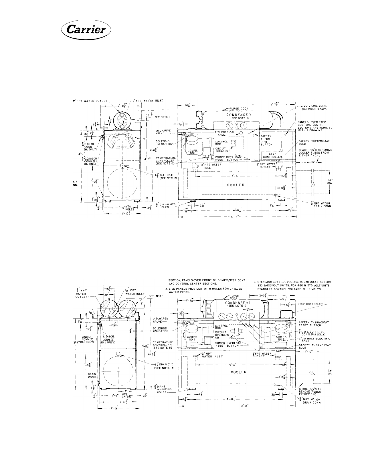
LEFT SiDE VIEW
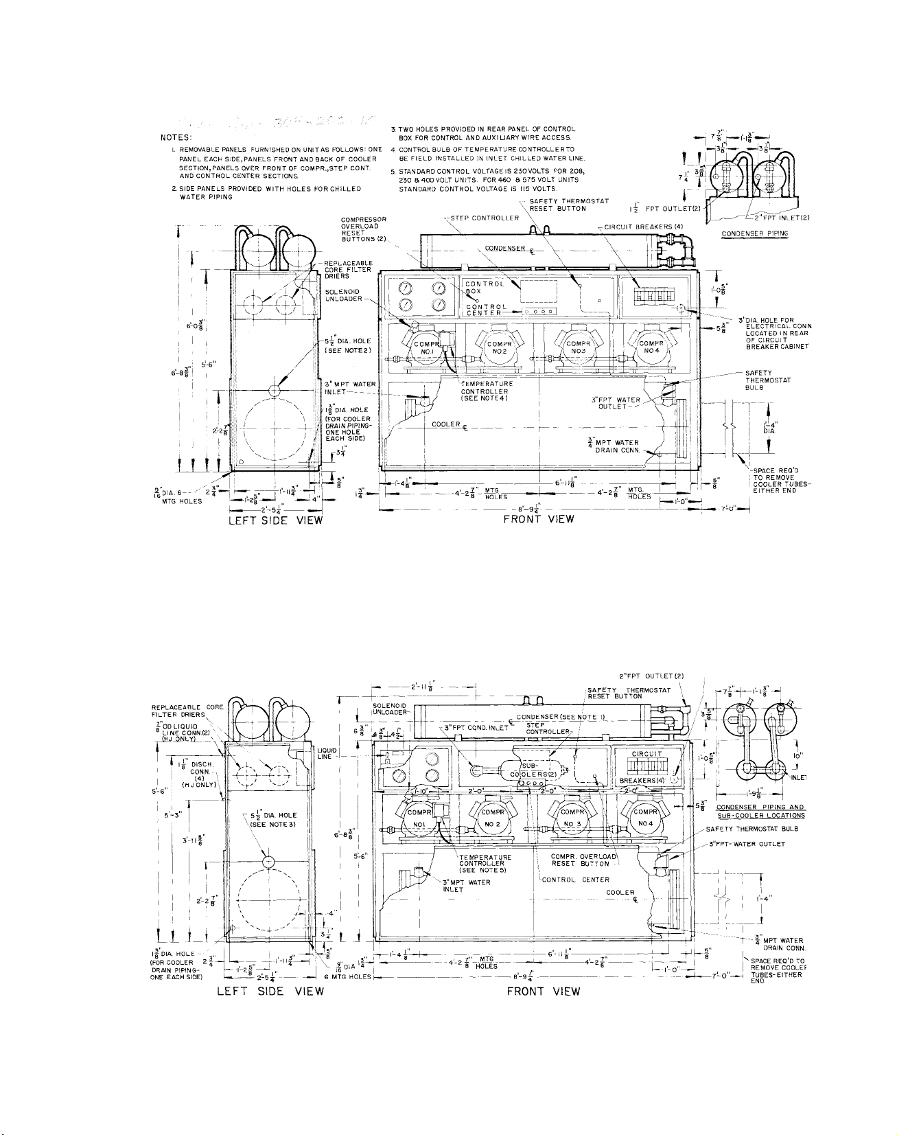
NOTES;
1. CONDENSER AND ATTACHED PIPING AS SHOWN ARE FOR
30HH MODEL ONLY.
2. REMOVABLE PANELS FURNISHED ON UN IT AS FOLLOWS'. ONE
PANEL EACH SIDE, PANELS FRONT AND BACK OF COOLER
SECTION, PANELS OVER FRONT OF COMPR., STEP CONT
AND CONTROL CENTER SECTIONS.
3. SIDE PANELS PROVIDED WITH HOLES FOR CHILLED
WATER PIPING.
FRONT VIEW
. TWO HOLES PROVIDED IN REAR PANEL OF CONTROL
BOX FOR CONTROL AND AUXILIARY WIRE ACCESS.
CONTROL BULB OF TEMPERATURE CONTROLLER TO
BE FIELD INSTALLED IN INLET CHILLED WATER LINE.
STANDARD CON T ROL VOLTAGE IS 230 VOLTS FOR 208,
230 aAOOVOLT UNITS FOR 460 a 575 VOLT UNITS
STANDARD CONTROL VOLTAGE IS 115 VOLTS.
Fig. 1 - 30HH,HJ015 Dimensiona! Data
NOTES;
I. CONDENSER AND ATTACHED PIPING AS SHOWN ARE FOR
30HH MODEL ONLY.
2 REMOVABLE PANELS FURN ISHED ON UNIT AS FOLLOWSlONE
PANEL EACH SI DE, PANELS FRONT AND BACK OF COOLER
. TWO HOLES PROVIDED IN REAR PANEL OF CONTROL
BOX FOR CONTROL AND AUXILIARY WIRE ACCESS.
. CONTROL BULB OF TEMPERATURE CONTROLLER TO
BE FIELD INSTALLED IN INLET CHILLED WATER LINE.
I
.
I
LEFT SIDE VIEW
FRONT VIEW
Fig. 2 - 30HH,HJ020 Dimensional Data
Page 4
30HH,HJ INSTALLATION
Carrier
SEE NOTE !
2”FPT water
OUTLET -
CONDENSERS FOR
30HH030
-------------------
CONDENSERS FOR
30HH025
I 2 FPT WATER
INLET—-.,
I2 FPT WATER
OUTLET—
FPT WATER
INLET
NOTES;
I CONDENSER ANDATTACHED PIPING AS SHOWN ARE FOR
30 HH MODEL ONLY.
2. REMOVABLE PANELS FURNfSHEO ON UNITAS FOLLOWS. ONE
PANEL EACHSIDE, PANELS FRONT AND BACK OF COOLER
SECTION, PANELS OVER FRONTOF COM PR., STEP CONT
AND CONTROL CENTER SECTIONS.
SIDE PANELS PROVIDED WITH HOLES FOR CHILLED
WATER PIPING.,,,
COND.
MPT WATER
INLET
CONDENSER
(SEE NOTE I )
V..y V
CONTROL
BOX
CIRCUIT
BREAKERS' y •
COMPR. OVERLOAD
RESET BUTTON -
4 TWO HOLES PROVIDED IN REAR PANEL OF CONTROL
BOX FOR CONTROL AND AUXILIARY WIRE ACCESS.
5. CONTROLSULB OF TEMPERATURE CONTROLLER TO
BE FIELD INSTALLED IN INLET CHILLEDWATER LINE.
6. STANDARD CONTROL VOLTAGE IS23OV0LTS F0R208.
230 9 400V0LT UNITS. FOR 460 S 575 VOLT UNITS
STANDARD CONTROL VOLTAGE IS 115 VOLTS.
STEP CONTROLLER
DISCH CONN.iHJ ONLY)
HJ025- I OD
HJ030- IffOD___________
SAFETY THERMOSTAT
RESET BUTTON
2 DIA. HOLE ELECTRIC
CONN.
_
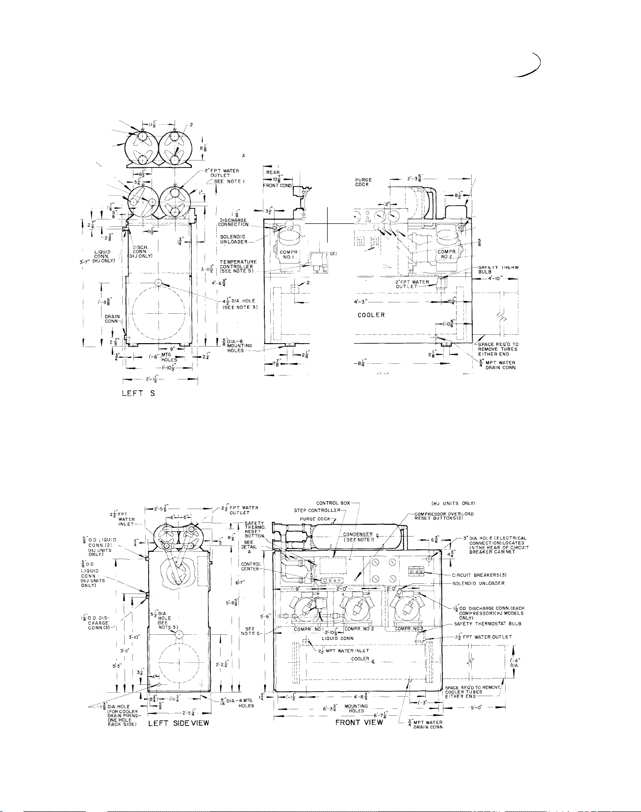
IDE VIEW
NOTES:
1 CONDENSER AND ATTACHED PIPING AS SHOWN ARE FOR
30HH MODEL ONLY.
2 REMOVABLE PANELS FURNISHED ON UNIT AS FOLLOWS: ONE
PANEL EACH SIDE, PANELS FRONT AND BACKOF COOLER
SECTION, PANELS OVER FRONT OF COMPR, STEP CONT.
AND CONTROL CENTER SECTIONS.
3 SIDE PANELS PROVIDED WITH HOLES FOR CHILLED WATER
PIPING.
FRONT VIEW
Fig. 3 - 30HH,HJ025,030 Dimensional Data
TWO HOLES PROVIDED IN REAR PANEL OF CONTROL
BOX FOR CONTROL AND AUXILIARY WIRE ACCESS.
. CONTROL BULB OF TEMPERATURE CONTROLLER TO
BE FIELD INSTALLED IN INLET CHILLED WATER LINE.
STANDARD CONTROL VOLTAGE IS 230 VOLTS FOR
208,230 5 400 VOLT UNITS FOR 460 5 575 VOLT
UNITS STANDARD CONTROL VOLTAGE IS 115 VOLTS.
h 5''— 2 ^
I' o.D. LIQUID LINE
Fig, 4 - 30HH,HJ045 Dimensional Data
Page 5
Carrier
INSTALLATION 30HH,HJ
notes:
1. CONDENSER AND ATTACHED PIPING AS SHOWN ARE FOR
30HH MODEL ONLY.
2. REMOVABLE PANELS FURNISHED ON UNIT AS FOLLOWS. ONE
PANEL EACH SIDE, PANELS FRONT AND BACK OF COOLER
SECTION, PANELS OVER FRONT OF COMPR., STEP CONT.
AND CONTROL CENTER SECTIONS.
3. SIDE PANELS PROVIDED WITH HOLES FOR CHILLED
WATER PIPING.
Fig. 5 - 30HH055 Dimensional Data
4. TWO HOLES PROVIDED IN REAR PANEL OF CONTROL
BOX FOR CONTROL AND AUXILIARY WIRE ACCESS
5. CONTROL BULB OF TEMPERATURE CONTROLLER TO
BE FIELD INSTALLED IN INLET CHILLED WATER LINE.
6. STANDARD CONTROL VOLTAGE IS 230 VOLTS FOR
208, 230 8 400 VOLT UNITS FOR 460 8575 VOLT
UNITS STANDARD CONTROL VOLTAGE IS 115
VOLTS.
-3’’DIA.H0LE FOR
ELECTRICAL CONN
LOCATED IN REAR
OF CIRCUIT BREAKER
CABINET
Fig. 6 - 30HH,HJ055 Dimensional Data
Page 6
30HH,HJ
INSTALLATION
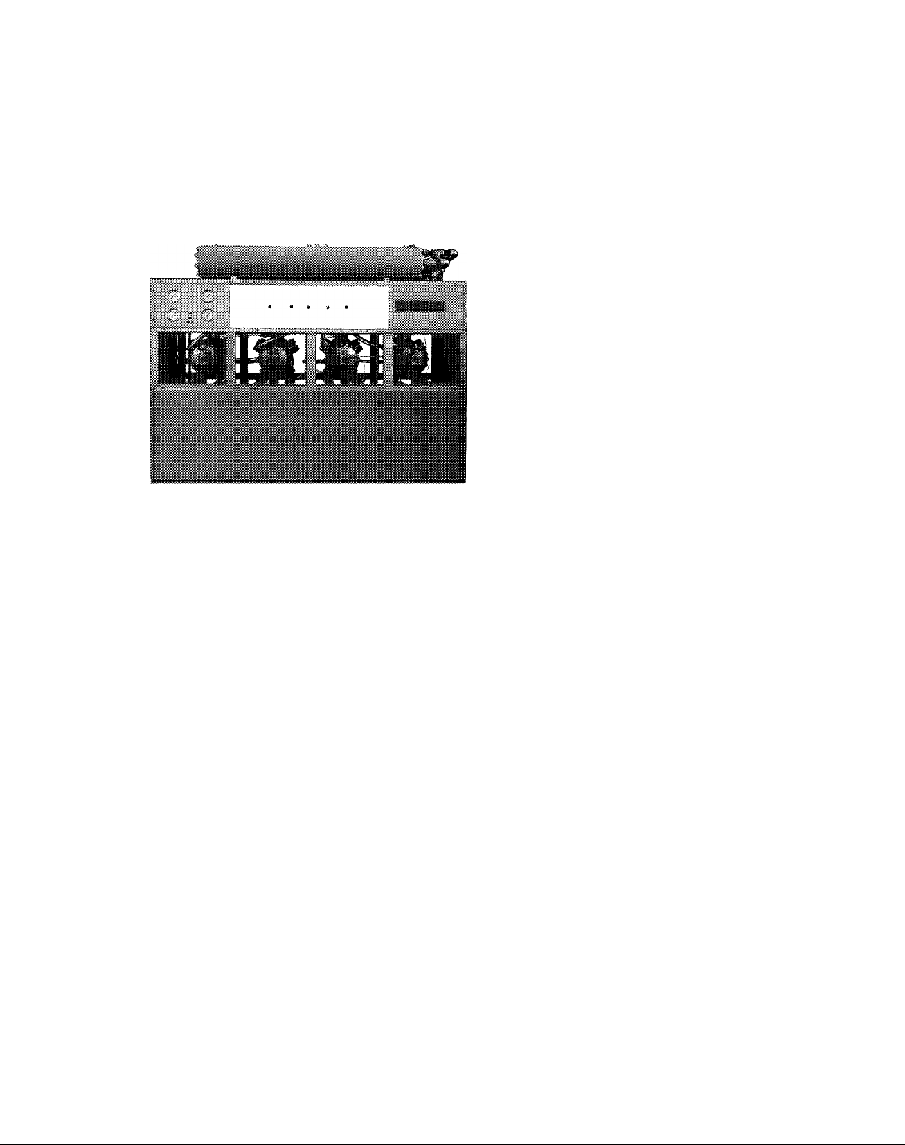
PRELIMINARY SURVEY
Before installation is started, a survey should
be made to establish the procedures and ma
terials required by installation personnel. See
cover picture for typical unit.
Storage
Because of the sensitive control mechanisms and
electrical devices incorporated in the 30HH,HJ
units, they should not be exposed to the weather.
Location
Always locate the unit indoors. In order to pre
vent freezing, the unit must be located in a space
where the temperature is at least 40 degrees.
Space Requirements and Clearance
Dimensions for the units are given in Table 1.
These dimensions are useful in checking door
clearances for moving the unit in and for deter
mining space requirements. A clearance of 2 to
3 feet should be left on each side and on the ends
for piping and electrical connections and also
to facilitate service operations. Clearance at
one end of the unit, equal to the length of the
unit, for servicing and removal of chiller tubes
must be provided.
Adequate Floor Strength
Approximate weights of units are given in Table
1. Make certain that the floor is strong enough
to support this weight. If necessary, add sup
porting structure to the floor for transferring
weight to the nearest beams. This can be done
with steel beams or reinforced concrete slabs.
Vibration Isolation
Rubber-in-shear vibration insulators and muf
flers are installed on, or furnished with, the
compressors of all units beginning with early
1961 production. The inter-connecting piping
must be sufficiently flexible to prevent vibra
tion transmission, if vibration still exists, vi
bration isolators may be used on the unit itself.
The field-purchased vibration mountings should
be placed under each corner of the package. The
weight distribution of all packages except the
30HH015 and 30HJ015 is such that each corner
mounting supports one fourth of the operating
weight. The weight distribution of the 30HH015
and 30HJ015 units is 55-45 side to side and sym
metrical front to back.
All phases of vibration isolation are fully de
scribed in Section 5X-1 of the Product Infor
mation book. Consult same for best results.
For additional information see "Compressor
Mounting."
MOVING AND PLACING UNIT
Moving
The skids on which the unit is mounted should
not be removed until the unit is at the final loca
tion. When handling the unit with a chain hoist,
remove the panels so that they will not be dam
aged by the sling. Do not attach the sling to
Table 1 - Weight and Overall Dimensions - 30HH.HJ Liquid Chiller Package
Shipping
Unit
30HH015
30HH020
30HJ015 1270
ЗОН] 020
30HH025 2200
30HH030 2550
30H]025
30HJ030 2150
30HH045
30HJ045 2455
30HH055 4622
30HH065 4700
30HJ065 3700
Wt. (lbs.)
1430
2200
1700
2100
3010
Operating
Wt. (lbs.)
1625
2150
1460
1800
1950
1950
1800
1850
3391 79-1/4 29-1/4
2835
5158
5236
4236
Uncrated Dimensions (Ins.)
Length
72
72
72
72
72
72 22-1/2
72
72 25-1/2
•79-1/4
105-1/4
105-1/4
105-1/4
Crated Dimensions (Ins.)
Width Height
22-1/2 54-3/4 76 30 63
22-1/2
22-1/2 47
25-1/2 47
22-1/2 54-3/4
25-1/2 47
29-1/4 66 83-1/2 33
29-1/4 80-3/8
29-1/4
29-1/4
54-3/4 76
54-3/4
47
79 83-1/2 33
80-3/8
Ó6
Length
76
76 30
76 30
76 30
76
76
109-3/4 33
109-3/4 33
109-3/4
Width Height
30 63
30
30 63
30 63
33
63
63
63
63
84-7/8
84-7/8
86-3/4
86-3/4
86-3/4
Page 7
Carrier
INSTALLATION
piping or equipment. Move the unit in an upright
position, and let it down gently from the truck
or rollers. On 30HH,HJ015-030 units the sling
can be placed under the frame channels at the
main support (Fig. 7). On 30HH,HJ045 thru 065
units, the sling can be placed under the skids.
Placing
To anchor the equipment;
1. Locate the hold down bolts as shown in the
dimension drawings. The areas where the
four corners will be located should be ap
proximately level before the unit is placed.
2. Set the unit in place and level with a spirit
level on the frame channels.
3. Bolt the unit to the floor. This is usually de
sirable for basement or ground floor instal
lations that can transmit vibration to the
ground without affecting the building struc
ture.
30HH,HJ
Fig. 7 - Rig Sling to Hoist Unit
(015-030 Shown)
Table 2 - Compressor Motor Physical Data
Unit Size
Compressor Type
Number
Sizes
Cylinder (Total No.)
Speed - 60 Cycle (rpm) 1750 1750 1750
- 50 Cycle (rpm) 1460 1460
Oil Charge (10 pt per compr) (pr) 10 20 20 20
Cylinder Unloading Devices (No.) t 2 1 1 1
*6D7 3 Compressors are used on rhe 30HH models
only. 30HJ Models are supplied with 6D75 com
pressors.
30HH, H]
0J5
1 - 6D73» 2 - 6D68 1 - 6D68
6
30HH, H]
020
2 2 2 3 4
12 12 12 18 24
30HH, HJ
025
1 - 6D73*
1460
t Each cylinder unloading device unloads two cylinders
of the compressor when it is energized.
30HH, HJ
030
Hermetic Reciprocating
2 - 6D73* 3 - 6D73* 1 - 6D68
1750 1750
1460
30HH, HJ
1460 1460 1460
045
30 40 40
30HH
055
3 - 6D73
1750
30HH, HJ
4 - 6D73*
065
4
24
1750
1
Page 8

30HH/HJ INSTALLATION
Table 3 - Condenser Physical Data
Carrier
Unit Size
Condensers (No.)
Condenser Type
Tubes or Coils, each
Effective External Surface, each (sq ft)
Water Side Volume, each (gal)
Nominal Shell Diam (in.)
Shell Length (in.)
Water Connections (Total No.)
Water Connection
Size (each cond. )
Coil or Tube Type
Coil or Tube OD (in.)
Nominal Shell Thickness (in.)
Materials
of
Construction
Max. Design
Working Press, (psig)
Inlet
Outlet
Shell
Coil or Tubes
Tube Sheet
Water Side
Refrig. Side
30HH015
1
6
82.7
3.5
10-15/16 10-15/16 10-15/16 10-15/16
42-5/8
2 4
1 - 2"
1 - 2"
30HH020
2
4
53.9
2.5
34-5/8
2 - 1-1/2”
2 - 1-1/2"
30HH025
2 2
Shell-and-Coil
1 - 6
1 - 4
1-53.9
1 - 82.7
1 - 2.5
1 - 3.5
1 - 34-5/8
1 - 42-5/8
4 4
1 - 1-1/2”
1 - 2"
1 - 1-1/2"
1 - 2"
Trufin
7/8 3/4
.278
Steel Steel
Copper Copper
Steel Steel
100
385
30HH030
6
82.7
3.5
42-5/8 42-5/8 77 77
2 - 2"
2 - 2” 3 - 2"
30HH045 30HH055
3
6
82.7
3.5
10-15/16
2 4
3 - 2"
2
Sheil-anc -Tube
64 64
165.7 165.7
5.0
10-3/4 10-3/4
2 - 2"
2 - 1-1/2"
Trufin
.307
100
385
30HH065
2
5.0
3
1 - 3"
2 - 2”
Г'
NOTE: The 30HH065 unit is supplied with two subcooiers (one per circuit) to provide 15 F of subcooling.
Page 9
m
INSTALLATION 30HH,HJ
Tabie 4 - Cooler Physical Data
Unit Size
Refrigerant Circuits (No.)
Tubes (No.) 136
Effective External Tube Surface (sq ft)
Length Between Tube Sheets (in.)
Shell Side Water Volume (gal) 20.4
Baffles (No.)
Baffle Spacing (in.)
Nominal Shell Diam. (in.)
Water Connection Size, IPS (in.)
Cooler Type
Construction
Tube Type and Size (in.) Prime Surface, 3/4 OD
Nominal Shell Thickness (in.) 1/4
Nominal Tube Sheet Thickness (in.)
30 HH, HJ
015
1
125
60-1/4
31
1-7/16
14
2
30HH, HJ
020
2
136
126
60-1/4 60-1/4 60-1/4
20.6
25 21
1-27/32 2-7/32
14
2
30HH, HJ
025
2
136
127
20.8
14 14
2
Shell-and-Tube, Fixed Tubesheet
30HH. HJ
030
2
136
128 179
21.0
17 15
2-3/4 3-1/4
2
Direct Expansion
1-3/8 Min.
30HH. HJ
045
2
188
60-1/4
26.6
16
2
30 HH
055
186
258 258
85-7/8
38.2
4-1/2 4-1/2
30HH, HJ
2
85-7/8
17 17
16 16
3
065
2
186
38.2
3
Materials
of
Construction
Maximum Design
Working Press.(psig)
Shell
Tubes
Tube Sheet
Baffles
insulation
Water Side
Refrig. Side 150
Closed Cell Foam Plastic, Vapor Sealed
Steel
Copper
Steel
Polypropylene
250
Page 10

30HH,HJ INSTALLATION
Table 5 - Refrigerant Circuits
Carrier
Unit Size
зоны, HJ015
30HH, HJ020
зоны, HJ025 2
ЗОНЫ, HJ030 2
ЗОНН, HJ045
30НН055 2
ЗОНН, HJ065
NOTE: 6D73 Compressors arc used on ЗОНЫ models. 6D75 Compressors are used on 30HJ miodels.
Circuits
1
2
2
2
Description of Refrigerant Circuit
(i) 6D73 or 6D75 Compr, Full Cooler Surface
(1) 6D68 Compr, 1/2 Cooler Surface
(1) 6D68 Compr, 1/2 Cooler Surface
(1) 6D68 Compr, 1/2 Cooler Surface
(1) 6D73 or 6D75 Compr, 1/2 Cooler Surface
(1) 6D73 or 6D75 Compr, 1/2 Cooler Surface
(1) 6D73 or 6D75 Compr, 1/2 Cooler Surface
(1) 6D73 or 6D75 Compr, 1/3 Cooler Surface
(2) 6D73 or 6D7S Compr, 2/3 Cooler Surface
(2) 6D73 Compr, 1/2 Cooler Surface
(1) 6D73 & (1) 6D68 Compr, 1/2 Cooler Surface 45
(2) 6D73 or 6D75 Compr, 1/2 Cooler Surface
(2) 6D73 or 6D75 Comipr, 1/2 Cooler Surface
Table 6 - Refrigerant Charge
Capacity (%)
100
50
50
40
60
50
50
33
67
55
50
50
Model ЗОНН, HJ
Refrigerant 22 (lb)
NOTES: 1. The refrigerant charges listed above do
not include the additional charge required
for remote condensers and piping with
ЗОН] models.
015
35
020
46
COMPRESSOR MOUNTING
All 30HH,HJ chillers, as shipped, have the com
pressor rigidly mounted to the frame with bolts
and steel pipe spacers. For proper operation,
the following procedure should be followed;
30HH,HJ020 to 030 units (Fig. 8):
1. Loosen the four (4) hold-down bolts on one
compressor.
2. Remove one hold-down bolt, lock washer
and nut on oil pump end of compressor. Lift
025 030
46 46
2. The 30HH015 and 30HH020 units are
shipped fully charged with refrigerant.
Other units are shipped with holding
charges only.
045 055
69
124
end of compressor and remove pipe spacer.
3. Tighten hold-down bolt which is diagonally
opposite spacer which was removed.
4. Install 3/8-16 X 1-1/2" bolt, supplied in bag
of fastenings, between compressor foot and
bracket. Reinstall lock washer and nut.
5. Loosen hold-down bolt tightened in step No. 3.
6. Repeat steps 2 thru 5 for other oil pump end
bolt.
065
140
10
Page 11
INSTALLATION
30HH,HJ
Fig. 8 - 30HH,HJ015-030 Compressor
Mounting
7. Remove both compressor motor end hold
down bolts, nuts, lock washers, and pipe
spacers, and replace with 3/8-16 x 1” bolts.
Reinstall lock washers and nuts to fasten
mounting brackets to resilient mounts.
FRONT
MOTOR END
REAR
PUMP END
Fig. 9 - 30HH,HJ045-065 Compressor
Mounting
6. Repeat steps 5 and 6 for the other motor end
fastenings of the compressor.
CONDENSER WATER PIPING
30HH,HJ045 to 065 units (Fig. 9):
The pairs of manifolded compressors are mount
ed on common mounting brackets. Be sure all
pipe spacers are removed for proper operation.
The mounting of the single compressor on
30HH,HJ045 units is similar.
1. Remove one 3/8-16 x 3-1/2” hold-down bolt,
nut, lock washer, and pipe spacer on the pump
end of the compressor.
2. Install a 3/8-16 x 1-3/4” bolt, supplied in
bag of fastenings, and reinstall nut and lock
washer from hold-down bolt, to fasten com
pressor to mounting bracket.
3. Repeat steps 1 and 2 for the other pump end
fastenings of the compressors.
4. Remove one 3/8-16 x 2-1/2” hold-down bolt,
nut, lock washer and pipe spacer on the motor
end of the compressor.
5. Install a 3/8-16 x 1” bolt, supplied in bag of
fastenings, and reinstall nut and lock washer
from hold-down bolt to fasten mounting
bracket to resilient mount.
Water supply lines should be as short as condi
tions will permit. The size of these lines is not
necessarily the same as those of the water valve
connections. All piping must be sized in accord
ance with tije pressure head available. This is
especially true on cooling tower applications.
See the System Design Manual, Part 3- "Piping
Design” for methods used in sizing pipe.
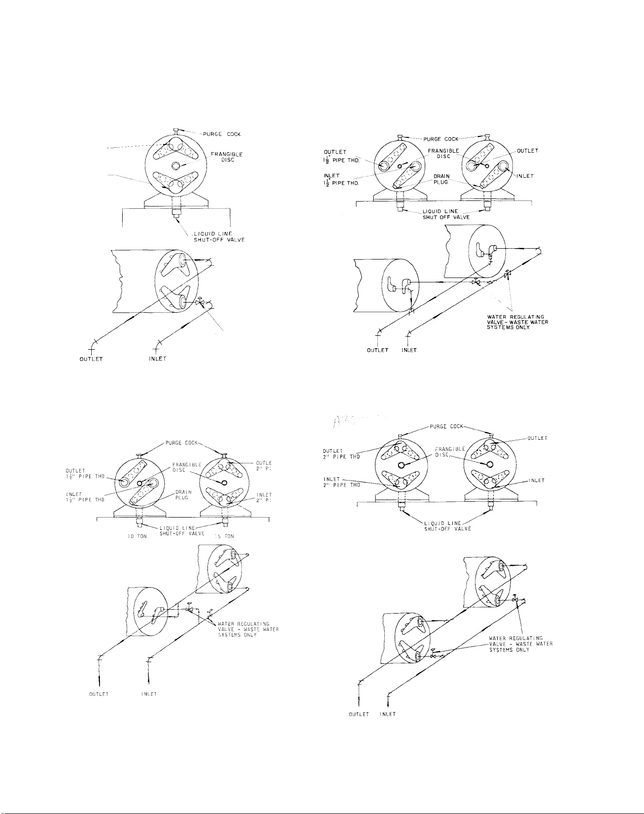
For installations using a waste water system, a
separate water regulating valve is required for
each refrigerant circuit. Water regulating valves
are not supplied by Carrier.
NOTE: Provide means for draining the
system in the winter and for repairs.
Figure 10 thru 16 show suggested piping
connections for each model when used
with waste water or cooling towers.
Frangible Disc Safety Union
Each condenser is provided with a frangible
disc that will relieve at 385 psig to protect the
system from excessive pressure.
Some local codes require piping from the relief
to the outdoors. The relief outlet size on both
models is 3/8” male flare.
11
1064
Page 12
зонн^ш
OUTLET
2" PIPE THD.
INLET
2" PIPE THD.
INSTALLATION
WATER REGULATING
VALUE-WASTE WATER
SYSTEMS ONLY
Carrier
Fig. 10 - 30HH015 Condenser Piping Fig. 11 - 30HH020 Condenser Piping
Fig. 12 - 30HH025 Condenser Piping
1064
Fig. 13 - 30HH030 Condenser Piping
12
Page 13

Carrier
INSTALLATION
30HH,HJ
Fig. 14 - 30HH045 Condenser Piping
Fig. 15 - 30HH055 Condenser Piping
13
Fig. 16 - 30HH065 Condenser Piping
1064
Page 14
30HH,HJ
Drain Connection
Drain connections are generally governed by
local codes. Water leaving the condenser is
under pressure and should not be connected
directly into sewer lines; otherwise water may
back up into other fixtures. Local codes nor
mally require connections similar to the one
shown in Fig. 17.
INSTALLATION
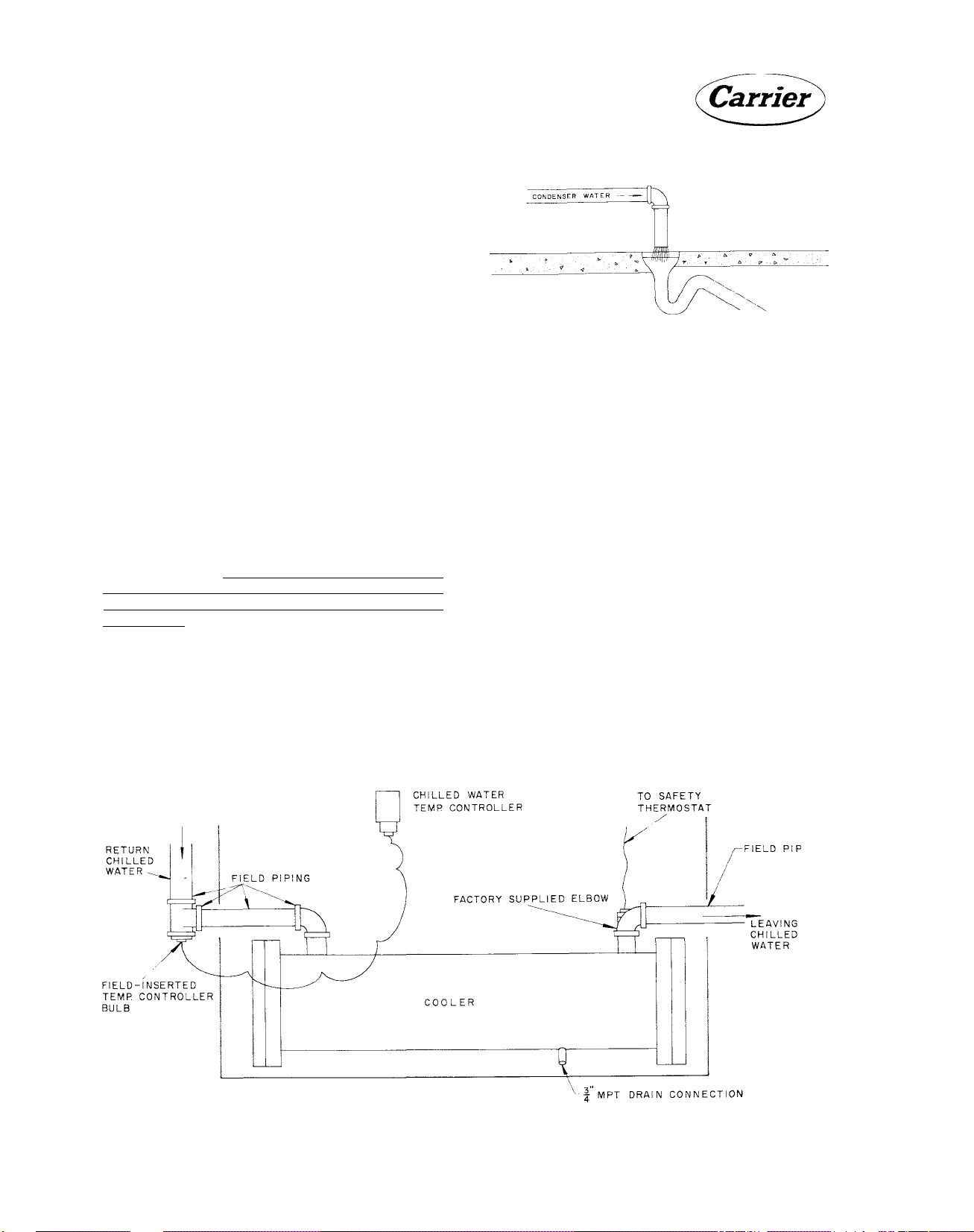
COOLER WATER PIPING
The cooler of each liquid chilling package is pro
vided with stubouts for chilled water piping con
nections. The water outlet stubout is provided
with a 90 degree elbow which contains the chilled
water safety thermostat bulb. Holes are pro
vided in both of the side panels for piping to the
stubouts.
The chilled water temperature controller is
mounted on the front of the unit and has the con
trol bulb and capillary tubing wrapped and taped
before shipping. It is required that the control
bulb be field inserted in the chilled water line.
It usually is inserted in the return or inlet chilled
water piping. Figure 18 shows a typical chilled
water piping arrangement in the vicinity of the
cooler. Details of the required remote chilled
water piping are outlined in the Carrier System
Design Manual, Part 3, "Piping Design."
Plan the piping so it has a minimum number of
changes in elevation. A manual or automatic
Fig. 17 - Drain Connections
vent-valve must be installed at the high points
in the line to permit venting of air from the
chilled water circuit. Standard practice for in
stalling forced water systems must be followed.
System pressures may be maintained by using a
pressure tank or a combination relief valve and
reducing valve.
It is recommended that thermometers be in
stalled in entering and leaving chilled liquid
lines. Provide drain connections at all low points
to permit complete drainage of the system. A
chiller drain shut-off valve should be connected
to the chiller drain line before placing the unit
in operation (Fig. 18).
Insulate piping to prevent heat loss and sweating.
Cover the insulation with a moisture seal. Do
not insulate piping before all leak testing has
been completed.
Fig. 18 - Cooler Water Piping, Front View
14
Page 15
Carrier
INSTALLATION
30HH,HJ
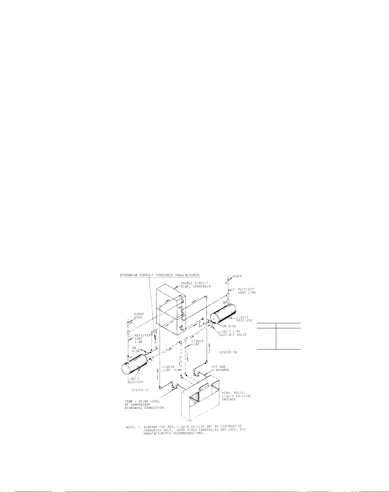
REFRIGERANT PIPING
For refrigerant piping sizing refer to Part 3 ’’Piping Design” - of the System Design Manual.
The ЗОНЫ and HJ Packaged Liquid Chillers are
leak tested at the factory and provided with a
holding charge of Refrigerant 22.
NOTE: 30HH015,020 fully charged with
R 22 at factory.
If the holding charge is still in the system upon
arrival at the erection site, the likelihood of leaks
is slight. If the unit is not under pressure, test
for leaks as outlined under Leak Testing.
NOTE: Be sure to open all stop valves
when testing for leaks.
30HJ UNIT
This section also applies to the 30HJ unit which
is to be connected to a remote condenser in the
field. Figure 19 is a typical refrigerant piping
diagram showing the 30HJ020 thru 030 unit and a
9H Evaporative Condenser. Simdlar connections
may be used for the 30Ш045 and 065 unit using
manifolded compressors. Figure 20-22 illus
trate typical refrigerant piping for 30HJ020 thru
065 units and air-cooled condensers. Receivers
have been omitted, but it must be recognized
that with this arrangement the refrigerant charge
is critical. An overcharged or undercharged
system can cause a loss of capacity. If a receiver
is not Included, an accurate refrigerant charge
must be maintained to assure efficient operation.
Figure 20-22 are shown to illustrate a typical
installation using 9A or 09DC016 air-cooled con
densers. These illustrations are to be used as a
guide when designing a system and are not in
tended to be used as an actual piping layout. Con
sult the ’’System Design Manual” and condenser
literature before designing the actual system.
Each 30HJ unit (except -015) consists of two
independent refrigerant circuits. Each circuit
must be isolated from the other.
Discharge lines and liquid lines are shown mani
folded at the units on 30HJ045 and 065 units to
permit a minimum amount of piping. Individual
discharge lines may be run from each compres
sor to the condenser if desirable. Liquid lines
must be manifolded as shown to enter the 30HJ065
unit to agree with the unit refrigerant circuit. In
dividual liquid line connections are necessary on
the 30HJ045 unit.
FROM TABLE - FOR VENTING AS SHOWN
MUFFLERS SHOULD
AS POSSISLE.
INSTALLED AS CLOSE TO THE COMPRESSOч
Fig. 19 - Typical Refrigerant Piping 30HJ020-030 Units
with 9H Evaporative Condenser
UNI T
30HU015
3ÛHJ020
30HJ025 15"
30HJ030
30HU0A5
3OHJO65
“X” DIM. *
6"
15"
15"
15"
1 5"
"X" DIM. - THIS IS
THE MINIMUM, ELEVATION
REQUIRED BETWEEN A
CONDENSER COIL OUTLET
AND A RECE!VER INLET
FOR THE TOTAL LOAD
WHEN RECE;VER 1S
VENTED TO COI I. OUTLET
HEADER (BASED ON 10'
OF HORIZONTAL PIPE,
1 VALVE AND 2 ELBOWS).
APPLIES TO 9H TYPE
EVAP. CONDENSER
- REFRIG. GAS
-REFIG. LIQUID
15
Page 16

30HH,HJ
In order to prevent condensed liquid refrigerant
or oil from causing damage to the compressor,
install a trap in the vertical discharge line near
the compressor. The trap may be installed within
or adjacent to the unit base. The height of the
trap (or loop) should be 6 inches for every 10
feet of vertical discharge line. If the height of
the vertical discharge line is such as to make
a single trap impractical, the loop can be re
placed by a check valve or several traps.
To prevent the formation of copper oxide when
brazing copper tubing, bleed a small amount of
dry nitrogen gas thru the piping. The nitrogen
will displace the air containing oxygen.
Complete all field piping before removing the
seals on the unit refrigerant piping. Upon com
pletion of the field piping, add a small amount
of refrigerant and build up the required test
pressure with dry nitrogen or other inert gas.
If a test pressure is not specified, ASA-B9
Code calls for 300 psig high side and 150 psig
low side test pressures for R 22.
NOTE: 1. Install mufflers as close to compres
sor discharge valve as possible.
2. Make sure a pressure relief device is
installed in the hot gas line or con
denser used with the 30HJ models.
INSTALLATION
Fig. 21 - Rafrigerant Piping to Three Air-
Cooled Condensers 30HJ045 (without Receivers)
Fig. 20 - Refrigerant Piping to Two Air-
Cooled Condensers 30HJ020,025,030
(without Receivers)
Fig. 22 - Refrigerant Piping to Four Air-
Cooled Condensers 30HJ065 (without Receivers)
16
Page 17

Carrier
INSTALLATION 30HH,HJ
LEAK TESTING
The Halide Leak Detector
The Halide Leak Detector pictured in Fig. 23
consists of a burner, needle valve, suction tube,
and a chimney with a copper reaction plate.
Some torches use alcohol and others use pro
pane fuel.
/Ч, '
Preparation
Before dehydrating a system make the following
preparations:
1. Obtain a pump that will produce a vacuum of
.2" Hg absolute. Do not use the compressor
as a vacuum pump. It is not designed for such
use and may be seriously damaged.
2. Pressure test system to be sure it is free of
leaks.
3. Obtain a vacuum indicator similar to that
shown in Fig. 24 (available thru local Carrier
Distributor).
4. Keep the ambient temperature above 60 F to
speed the evaporation of moisture.
и
1 SAE PLUG , - . ,
l."SAE FLARE NUT--
--------------
S--------------r*
u
I »SOLATIO«-
Fig. 23 - Halide Leak Detector
To use the leak detector;
1. Adjust the flame so the top of the flame cone
is level with or slightly above the chimney.
2. Place the end of the suction tube at the point
to be tested. The tube pulls in a sample of
air to the burner where the refrigerant is de
composed by reaction with the copper plate.
3. Observe the color of the flame. Small leaks
give a greenish tint and large ones a vivid
blue. Leaks can also be detected with a soap
solution or an electronic gun.
DEHYDRATE THE SYSTEM
If there has been a leak in the 30HH unit or after
field piping the 30HJ unit, the system must be
evacuated.
Moisture in the system causes oil-sludge and
corrosion, it is likely to freeze up the expansion
valve of a low temperature system. The best
means of dehydration is evacuation with a pump
specially built for this purpose.
TME«MC«ETEft
distilled WATER
L.. J T
Fig. 24 - Vacuum Indicator
Description and Use of the Vacuum Indicator
The vacuum indicator consists of a wet bulb
thermometer in an insulated glass tube contain
ing distilled water. Part of the tube is exposed
so the thermometer can be read and the water
level checked. When the vacuum indicator is
connected to the vacuum pump suction line, the
thermometer reads the temperature of the water
in the tube. The temperature is related to the
absolute pressure in the tube. Table 7 gives
the absolute pressures corresponding to var
ious temperatures.
¿HahdlQ the vacuum indicator with care. It must
be vacuum tight to give a true reading. The top
17
Page 18

INSTALLATION
Table 7 - Vapor Pressures of Water
Temperature, degrees F
Observed on Vacuum
indicator
70
60
55
50
45
40
35
32
NOTE: To determine the vacuum in inches of
mercury subtract the absolute pressure
from the barometer reading.
seal of the indicator is not designed to support
a long run of connecting tubes. Fasten the tubes
to supports to prevent damage.
Use only distilled water in the indicator. Be
sure the wick is clean. Oil or dirt on the wick
causes erroneous readings. To prevent loss of
oil from the vacuum pump and contamination
of the indicator;
Absolute Pressure
Inches of Mercury
0.739
0.522
0.436
0.363
0.300
0.248
0.204
0.180
value corresponding to the vapor pressure of
the water in the indicator, the temperature
will start to drop. In the example shown in
Fig. 25, the ambient temperature and the
temperature of the water in the indicator is
60 F. Starting at 60 F and 0 time the temper
ature of the water in the indicator remains
at 60 F until the pressure in the system is
pulled down to the pressure corresponding to
the saturation temperature of the water (60 F).
At this point the moisture in the system will
start to boil. The temperature drops slowly
until the free moisture is removed (35 F).
Dehydration is nearly completed at this point
provided the ambient temperature remains
at 60 F or higher. If the ambient temperature
were lower than 60 F ice might form before
moisture removal is complete.
3. Continue the dehydrating operation until the
vacuum indicator shows a reading of 35 F
which corresponds to a pressure of 0.204”
Hg absolute. This may take several hours. It
may be advantageous to run the pump all
night.
4. With the pump still running, open the system
at a point furthest from the pump and admit
air thru the drier. Close system and repeat
steps 2 and 3. Vapor left in the system is
thus greatly diluted and almost completely
removed by double dehydration.
1. install a shut-off valve in the suction line at
the vacuum pump.
2. Install a shut-off valve in the suction line at
the vacuum indicator.
3. When shutting off the pump, close the indi
cator valve, the pump valve and turn off the
pump in that sequence.
Procedure for Dehydrating the System
1. Connect the pump and vacuum indicator to
the system. Put a ’’jumper" line between the
high and low side so that the pump will draw
a vacuum on all portions of the system. Open
the compressor shut-off valves. Start the
pump.
2. Open the indicator connection shut-off valve
occasionally and take a reading. Keep the
valve open at least three minutes for each
reading. (Keep the valve closed at all other
times to decrease the amount of water the
pump must handle and hasten dehydration.)
When the pressure in the system drops to a
5. After evacuation, turn off the pump suction
valve and break the vacuum by admitting
refrigerant.
START-UP PROCEDURES
initial Check
Do not attempt to start the ЗОНЫ and HJ Liquid
Chiller even momentarily until the following
steps have been completed.
1. Check all auxiliary components of the instal
lation such as chilled liquid circulating
pump, cooling tower if used, air handling
equipment, or other equipment to which the
chiller supplies liquid. Consult the manufac
turer's instructions.
2. Check safety thermostat. See "Safety Ther
mostat Adjustment" under "CHECKING
THE CONTROLS."
3. Backseat (open) the compressor suction and
discharge shut-off valves. Close the valves
18
Page 19

INSTALLATION
30HH,HJ
TIME
Fig. 25 - Dehydration Puii-Down Curve
one turn to allow pressure to reach the
gages.
4. Open the liquid line shut-off valves at the
condensers (30HH if using the vapor charg
ing method - see "Charge With Refriger
ant”) or the inlet, outlet, and vent valves on
the receivers (30HJ).
5. Open the valves to the capillaries of the
water regulating valves (when used).
6. Fill the chilled liquid circuit completely
with clean water or other non-corrosive
fluids to be cooled. Bleed all air out of the
high points of the system.
7. If the condenser is cooled by waste water,
open the water supply valve. If it is cooled
by a cooling tower, fill the tower with water.
8. Start the air handling equipment or other
equipment to which the 30HH or HJ is con
nected.
lay and remove protective paper between
contacts of the balancing relay in the step
controller.
Start Up
Upon completing the initial check, charge the
unit with refrigerant. (See "Charge with Refrig
erant.”)
IMPORTANT: 30HH015,020 units are
fully charged at factory.
The unit should only be started under the super
vision of a refrigeration mechanic who is famil
iar with the accepted operating practices for
refrigeration systems.
1. Open all compressor or system valves that
may have been closed during or after charg
ing.
2. Start the unit by pushing the "START" and
"STOP” button.
9. Set the temperature controller (page 24).
10. Check tightness of all electrical connec
tions.
11. Remove cardboard spacer from recycle re -
3. Check all controls for proper operation. (See
"Check Controls.”)
4. Adjust watfer regulating valve to the most
economical pressure for the locality. Nor
mally 200 to 230 pounds for F 22.
19
Page 20

30HH,HJ INSTALLATION
TYPE LIQUID SHUT-OFF VALVE CHARGE
USING VAPOR METHOD
Fig. 26 - 30HH Condenser Liquid Line Shut-Off Valves
5. Check chiller leaving temperature to see
that it remains well above freezing.
6. Check compressor oil level ("Oil Charge”).
CHARGE WITH REFRIGERANT
Each system in the 30HH and HJ units must be
charged individually.
IMPORTANT: 30HH015,020 units are
fully charged at factory.
Charge early models of the 30HH015 to 030 units
using the vapor charging method.
Charge later models of the 30HH units using
liquid charging method. A redesign of the con
denser liquid shut-off valve makes it possible
to charge liquid refrigerant thru the gage port
directly into the chiller, when the valve is in the
front seated position. Check Fig. 26 showing
both valves to determine the method of charging
to be used.
CAUTION: When charging the units,
circulate water thru the condenser
(30HH) and chiller (30HH and HJ) at all
times to prevent freezing. Freezing of
equipment with resulting damage is
considered abuse and not covered by
the Carrier Warranty.
Vapor Charging Method
Vapor charge the units thru compressor suction
shut-off valves as follows:
2. Connect a refrigerant cylinder loosely to the
gage connection of the suction shut-off valve.
The charging line should contain a drier.
3. Purge the charging line and tighten the con
nections.
4. Turn the stem of the suction shut-off valve
clockwise a couple of turns.
5. Stand the cylinder upright so that only gas is
charged into the system. Crack valve on the
charging cylinder and break vacuum (30HJ
units) with refrigerant vapor. Open the valve
of the charging cylinder and start the com
pressor. (See ”Start-Up Procedures.”) Al
low the compressor to cycle on the low-
pressure cut-out until the refrigerant charge
builds up sufficiently to permit continuous
compressor operation.
As the cylinder is discharged, its pressure
will eventually drop to the same level as suc
tion pressure. The remaining refrigerant can
be drawn from the cylinder by front seating
the suction shut-off valve and pulling a vac
uum on the cylinder.
6. Check the refrigerant charge frequently at
the moisture liquid-indicator. A steady flow
of liquid refrigerant will indicate a sufficient
charge.
7. When the unit is sufficiently charged, close
the cylinder valve, backseat the suction shut
off valve, and remove the charging apparatus.
1. Backseat the suction shut-off valve.
Replace the plug in the suction shut-off valve.
20
Page 21

Carrier
INSTALLATION 30HH,HJ
Liquid Charging Method
Liquid charge the units thru the condenser liquid
line shut-off valves.
1. Backseat condenser liquid line shut-off valve.
2. Connect a refrigerant cylinder loosely to the
gage connection of the condenser liquid line
shut-off valve. Purge the charging line and
tighten the connections.
3. Weigh the refrigerant cylinder (if possible).
4. Front seat the condenser liquid shut-off valve.
5. if the system has been dehydrated and is
under vacuum, break vacuum with refriger
ant (Gas charge). Build system pressure to
58 psi for R 22 (32 F). Invert refrigerant
cylinder so that liquid refrigerant will be
charged.
6. Allow the compressor to cycle on the low
pressure cut-out until sufficient pounds of
refrigerant have been added (Table 6).
7. When the unit is sufficiently charged, close
the cylinder valve, backseat the liquid line
shut-off valve, and remove the charging ap
paratus. Replace the cap in the liquid line
shut-off valve.
evaporative condenser models, it may be neces
sary to add oil at the job site. Observe the oil
level closely at startup and add oil, if required,
to bring the level in the crankcase to the middle
of the bull's-eye during steady operation.
To Add Oil
1. Close suction shut-off valve and pump down
crankcase to 2 psig. (Low pressure cut-out
must be shorted.) Wait a few minutes and
repeat as needed until pressure remains at
2 psig.
2. Remove oil fill plug to the right of the bull'seye and add oil thru plug hole.
3. Replace plug.
4. Run compressor for about 20 minutes and
check the oil level.
CAUTION: To insure trouble free oper
ation, use only Carrier approved com
pressor oil, Specification No. PP-33-2.
Do not re-use oil that has been drained
out, or oil that has been left open to the
atmosphere.
To Remove Oil
1. Pump down compressor to 2 psig gage.
NOTE: Where it is impossible to weigh
the refrigerant cylinder, the initial re
frigerant charge must be an approxi
mation. After it has been added, back
seat the liquid line shut-off valve and
allow the unit to operate. A clear flow
of liquid in the liquid-moisture indica
tor, indicates a satisfactory charge.
If the charge is not sufficient, add re
frigerant until a clear flow of liquid
show in the glass.
CAUTION: Be careful not to overcharge
the system. Overcharging results in:
(a) Higher discharge pressure with
higher cooling water consumption.
(b) Possible compressor damage.
(c) Higher power consumption.
OIL CHARGE
The 30HH,HJ units are charged with oil at the
factory (Table 2). Because of added piping with
2. Loosen the 1/4” pipe plug in compressor
base and allow the oil to seep out past the
threads of the plug.
CAUTION: The crankcase will be under
slight pressure. Be careful not to re
move the plug; the entire oil
may be lost.
charge
CHECK THE CONTROLS
Expansion Valve
The thermal expansion valves control the flow
of liquid refrigerant by maintaining constant
superheat of the vapor leaving the cooler. They
are pre-set at the factory to maintain a super
heat of 8 F. Do not attempt to adjust them unless
you are certain it is absolutely necessary.
Safety Thermostat Adjustment
The safety thermostat is of non-cycling, manual
reset type. It has an adjusting dial with a stop
set at 36 F for normal chilled water applica
tions, but can be readjusted for a lower stop if
21
Page 22

30HH,HJ INSTALLATION
glycols or brines are to be cooled. The adjust
ment tolerance is commonly j- 1 F.
DAMAGE DUE TO THE FREEZING OF A CHILL ER IS NOT COVERED BY THE WARRANTY.
The safety thermostat bulb is located in the
leaving chilled water piping stubout.
IMPORTANT: This thermostat should
be checked at the time of installation
and at least once every season. If the
bulb is damaged in handling, its cali
bration may be off.
To check the safety thermostat:
1. Place the thermal bulb in a vacuum bottle
filled with water and add crushed ice.
NOTE: This is an insert type bulb. On
earlier units, removal opens water sysexcept on 30HH,HJ045 thru 065 units
which use a sealed well. Later units
all use a sealed well.
I ‘-f
FIXED IMDICATOR
ADJUSTING SLOT
2. Stir the contents with a thermometer and
note the temperature at which safety thermo
stat cuts out.
3. Reset the safety thermostat if necessary. To
set the control, use screwdriver in slot and
rotate dial until the desired temperature at
which compressor is to stop is directly under
indicator "B”.
To recalibrate the safety thermostat;
1. Measure the temperature as close to the bulb
as possible, immediately after the compres
sor stops.
2. Break the painted seal between the dial and
the adjusting plate with a knife.
3. Carefully loosen the two dial screws. Be care
ful not to turn the brass cylinder below the
dial during this or any of the following oper
ations.
4. Turn the dial ONLY so that the fixed indica
tor points to thè temperature measured at
step 1.
5. Carefully tighten the dial screws.
Fig. 27 - Safety Thermostat
High and Low Pressure Controls
Pressure control settings are shown in Table 8.
The 30HJ high pressure control settings are suit
able for use with either air-cooled or evaporative
condensers. The control setting (Table 8) is a
fixed setting and is nonadjustable.
Check the high pressure switch setting by slowly
closing the discharge shut-off valve. The com
pressor should shut down when the discharge
pressure reaches 260 or 355 psi (as required)
and start up when the pressure drops to 210, or
255 psi (as required).
The 30HH high pressure switches are adjustable
and equipped with a stop to prevent field setting
above 280 lbs.
To check the low pressure switch, close the
suction shut-off valve and allow the compressor
to pump down. The compressor should cut out
when the suction pressure falls to 46 psig, and
automatically start up again when the suction
pressure builds up to 83 psig.
Both sides should be checked at startup and at
least once a year thereafter.
22
Page 23

Carrier
INSTALLATION 30HH,HJ
Tabie 8 - Pressure Contro! Settings
High Pressure
Cutout
Cutout
Model
30HH
30HJ
Liquid Line Solenoid Valves (30HJ models only) -
All 30HJ condenserless models are provided with
a liquid line solenoid valve in each refrigerant
circuit. These valves and the low pressure cut
out switches provide pumpdown control of idle
refrigerant circuits when the unit is in operation.
(Psig)
260 210
355
Cut-in
(Psig)
255
Low Pressure
Cutout
Cutout
(psig)
46
46
Cut-in
(psig)
83
83
Crankcase Heaters
All compressors are furnished with crankcase
heaters to prevent accumulation of liquid in the
compressors. They are inserted into blind holes
in the compressor bottom cover. Electrically,
they are wired into the control circuit by con
necting them to the normally closed auxiliary
contacts on the compressor starters. The crank
case heaters are energized at all times when
the unit is not in operation.
Electrical Characteristics: 75 watt, 230 volt,
single phase, 50/60 cycle for each crankcase
heater on 230 volt units; 75 watt, 115 volt single
phase, 50/60 cycle for 460 volt and 575 volt
units.
STARTERS AND OVERLOADS
The starters have been selected and the over
loads have been sized at the factory to give prop
er protection to the compressor motor. Do not
increase their size or bypass their connections.
If trouble is encountered, the cause should be
found and corrected before the overloads are
reset.
Compressor Thermal Protection
An internal thermostat is located in the motor
windings of each compressor. Should the tem
perature of the compressor rise too high, the
thermostat will trip and stop the compressor.
It will not restart until the temperature drops.
On the part winding compressor, the thermo
stat is located externally on the compressor
housing.
CIRCUIT BREAKERS
Circuit breakers provide separate branch cir
cuit protection, one for each compressor. They
are jumpered so that only one power lead to the
unit is required.
When branch circuit overload causes the break
ers to trip, they must be manually reset, by
throwing the switch off and on again. The cause
of the overload should be determined and rem
edied before restarting.
Control Circuit
To stop unit, push ’’STOP-START"
center of the gage panel.
button in
Table 9 - Circuit Breaker Trip Amperes
Circuit Breaker Size (Amps)
208-3-60
Compressor and Unit
6D73 (HH) 90 90 40
6D75 (HJ) 90 90 50
6D68 (HH) 50 50
6D68 (HJ) 70
230-3-60
230-3-50
50 30
23
460-3-60
400-3-50 575-3-60
40
40
25 20
30
Page 24

30HH,HJ
Carrier
INSTALLATION
Two eight ampere fuses protect the control cir
cuit against overload. The control light will be
on whenever the control circuit is energized.
Disengage the fuse caps to remove blown fuses.
Fig. 28 - Gauge Panel (30HH,HJ045)
The "X" values (Table 10) were established by
experimentation and are such that the compres
sor is prevented from cycling more than once
in a five minute period.
The throttling range is determined as follows;
Throttling Range (modulating) =
Design Rise + "X”
The throttling range setting is arrived at by
entering the graph below at the "set point” and
moving across an amount equal to the throttling
range. The setting is read from the top scale
and will fall somewhere between min. - F. To
illustrate, with a 30HH065 Chiller, a 4-compres
sor unit, at a 10 F design rise, 45 F leaving
chilled water temperature, the set point would
be 45 - 1 = 44 F. The throttling range would be
10 + 1 = F.
Entering the graph at 44 F and moving across
11 F indicates a throttling range setting of just
under "A”.
Table 10 - ”X” Values, F
WATER REGULATING VALVE
The water regulating valve should be set to
maintain the most economical head pressure as
determined by the design engineer, based on the
relative cost of water and electricity in a given
area. It should not be adjusted to compensate
for high head pressures caused by fouled con
denser tubes, excess refrigerant or the pres
ence of noncondensables. Due to changes in
water temperatures, it may be necessary to
adjust the valve seasonally. After adjusting for
the economical head pressure, the machine
should be shut down. The water regulating valve
should shut off the flow of water in a few min
utes. If it does not, it will be necessary to
raise the head pressure setting. The water reg
ulating valve is used for city water and in
some cases with multiple units on a single
cooling tower.
TEMPERATURE CONTROLLER ADJUSTMENT
The chilled water temperature controller must
be adjusted in the field before initial startup.
Two adjustments are required - Set Point (main
scale, 15 - 90 F) and Throttling Range (modu
lating, min - F).
Design Rise F
No. of Comp. 8 10 12
1
2
3
4
SET POINT
ADJUSTMENT SCREW
2.0
2.0
1.25
.75
^ADJUSTMENT SCREW
2.5
2.5
1.5
1.0
THROTTLING RANGE (MODULATING)
3.0
3.0
1.75
1.25
THROTTLING
RANGE
SCALE
The set point is determined as follows ;
Set Point = Design Leaving Chilled Water
Temperature - ”X”
Fig. 29 - Chilled Water Temperature
Controller
24
Page 25

Carrier
INSTALLATION
THROTTLING (MODULATING) RANGE SETTING
MIN. A B C DE F
.CONTACTORS
CURRENT OVERLOADS
Fig. 30 - Temperature Contro!ie‘r Graph
(HI-LOW STEP
PRESSURESTATS CONTROLLER
SAFETY HI-LOW CONTACTORS
THERMOSTAT PRESSURESTATS / \
I
TERMINAL STRIP
Fig. 31 - Control Box - 30HH.HJ055
25
CURRENT OVERLOADS
Page 26

30HH,HJ INSTALLATION
CAM
SWITCHES
BALANCif'^G
POTENTIOMETER r~ TRANSFORMER
TEMPERATURE.
BRIDGE
Carrier
I
COMPRESSOR ; «
(2 BANKS OF—i
UNLOADING) * '•
^ oH
Fig. 32 ~ Step Controller
K)
•n
Fig. 33 - 30HH015 Chiller with Front Panel
Removed
Fig. 34 - 30HH015 Control Panel
26
Page 27

INSTALL/
♦
Fig. 35 - 30HH.HJ015 Wiring Diagram
Page 28

non
30HH,HJ
f jTRANS-
nlpORMER
balancing
RELAY
Idxgxg.
TERMINALS ON MAIN TERMINAL StRiR TERMINALS ON PANEL LIGHT
□
TERMINALS ON STEP CONTROLLER f / TERMINALS ON PRESS. SWITCH
o
TERMINALS ON TEMPERATURE CONTROLLER
A
NOTES
ALL WIRING SHOWN IS FACTORY WIRING EXCEPT AS OUTLINED IN NOTE 2.
208 VOLT a 230 UNITS HAVE 208/230 VOLT CONTROL CIRCUITS. ON THESE UNITS ONLY, LEADS ARE
SUPPLIED FROM NUMBER i CONTACTOR TO TERMINALS 182 FOR TH£ PURPOSE OF ENERGIZING THE
CONTROL CIRCUIT. 460 8 575 VOLT UNITS HAVE US VOuT CONTROL CIRCUITS. AND A SEPARATE 115 VOLT
SOURCE MUST BE FIELD SUPPLIED THROUGH A FUSED DISCONNECT SWITCH TO TERMINALS 18 2.
FACTORY WIRING IS IN ACCORDANCE WITH THE NATIONAL ELECTRICAL CODE. ANY FIELD MODIFICATIONS
OR ADDITIONS MUST BE IN COMPLIANCE WITH ALL APPLICABLE CODES,
CONTROL CIRCUIT FUSES MUST ALWAYS REMAIN IN THE CONTROL CU.RCUiT. THE FUSES ARE i/4" x 1 1/4"
CERAMIC TUBE RATED AT 8 AMPS FOP 220 VOLT Cl RCUS TS AND 15 AM PS FOP I! 5 VOLT CIRC U IT S.
MINIMUM SWITCH RATING FOR TERMINALS [T] , [Tj ^20 VOLTS IS VOlT-AMPERES EACH.
REMOVE JUMPERS AS REQUIRED FOR AUXILIARY fNTERL<^KS.
MAXIMUM EXTERNAL CONTINUOUS LOADS TO BE CONNECTED BETWEEN TERMINALS [TIaND / 9 /, AND
TERMINALS AND ARE 2^ VOLT-AMPERES EACH- ‘
LOAD SWITCHES ARE SHOWN WITH I
£ND)TO OPERATE LOAD SWITCHES
I5CVA TRANSFORMER REQUIRED FOR DEVICES SHOWN ON CONTROL WIRING DIAGRAM. IF ADDITIONAL CONTROLS ARE
USED. THE TRANSFORMER SIZE MUST 8E INCREASED ACCORDINGLY.
FULLY UNLOADED, CAMSHAFT MOTOR RUNS CC W. (FROM POTENTIOMETER
1 IN SEQUENCE AS CHILLED WATER TEMPERATURE INCREASES,
o
----
^ ^^
ross-the-Line and Part Winding)
27
Page 29

INS
i^SOLENOlD UNLOaOER
COMPR, MOTOR
POWER TERMINAL
\ MOTOR TERMINALS i-2-3
TH'STAT 8-9
“7^
•^CRANKCASE
HEATER
TERMINAL 7 NOT USED
TEMPERATURE CONTROLLER
HI-LOW
IHI-LOW
\[U ZjE7
SWITCH
! SWITCH
CONTACTOR
NO.
CIRCUIT
BREAKER
N0,1
|!3|i2|l0j7i6[5iA|Aj4j2| l]
TERMINAL STRIP
OilTSOL CENTER
CIRCUIT
BREAKER
N02
CHILLED
WATER SAFETY
THERMOSTAT
CONTACTOR
N0.2
0 L
OL 0 L
2 3
LOCATION OF CONTROL COMPONENTS
TEMP CONTROL BULB
Fig. 36 - 30HH.HJ020, 025
28
Page 30

ALLATION
AUX. CONTACTS POR
CRANKCASE HEATERS
CONTROL CiRCUiT POWER LEADS
220 V. ONLY (SEE NOTE 2)
CONTACTOR
POWER WIRING
CIRCUIT BREAKERS
Carrier
FIELD POWER
SUPPLY (SEE NOTE 3)
VOLTSPHASE.
CYCLE.
CAM
SHAFT
BALANCING POT-
LiMiT SWITCHES
CAM OPERATED
LOAD SWITCHES
i^STEP CONTROLLER
TOP VIEW
7^ /
TRANS
FORMER
iBALANCING
RELAY
WHEN
ENERGIZED)
LEGEND
TERMINALS ON MAIN TERMINAL STRIP
□
TERMINALS ON STEP CONTROLL
о
TERM! NALSONTEMPERATURE CONTROLLER
A
ER / / TERMINALS ON PRESS,
TERMINALS ON PANEL
NOTES
1. ALL WIRING SHOWN IS FACTORY WIRING EXCEPT AS OUTLINED IN NOTE 2.
2. 208 VOLT a 230 UNITS HAVE 208/230 VOLT CONTROL CIRCUITS. ON THESE UNITS ONLY, LEADS ARE
SUPPLIED FROM NUMBER ! CONTACTOR TO TERMINALS 132 FOR THE PURPOSE OF ENERGIZING THE
CONTROL CIRCUIT. 460 8 575 VOLT UNITS HAVE 115 VOLT CONTROL CIRCUITS. AND A SEPARATE 115 VOLT
SOURCE MUST BE FIELD SUPPLIED THROUGH A FUSED DISCONNECT SWITCH TO TERMINALS 182.
3. FACTORY WIRING IS 1N ACCOR0ANCE WITH THE NATIONAL ELECTRICAL CODE. ANY FIELD MODIFICATIONS
OR ADDITIONS MUST BE IN COMPLIANCE WITH ALL APPLiCASLE COOES.
4. CONTROL CIRCUIT FUSES MUST ALWAYS REMAIN Ш THE CONTROL CIRCUIT. THE FUSES ARE 1/4" x I 1/4"
CERAMIC TUBE RATED AT 8 AMPS FOR 220 VOLT CIRCUITS AND 15 AMPS, FOR И5 VOLT CIRCUITS.
5. MINIMUM SWITCH RATING FOR TERMINALS .[J] . LI] 220 VOLTS IS 500 VOLT-AMPERES EACH.
REMOVE JUMPERS AS REQUIRED FOR AUXILIARY INTERLOCKS.
6. MAXIMUM external ^il^TINUOUS LOADS TO 8E CONNECTED BET WEEN TERMIN ALS FÄIaNO / 9 / AND
TERMINALS РГ1 AND iTl ARC VOLT-AMPERES EACH. ' ' ^
7 load switches are shown WITH UNIT FULLY UNLOAOCD.CAMSHAFT MOTOR RUNS C.C.W.{FROM POTENTIOMETER
ENOJTO OPERATE LOAD SWITCHES 1 THRU 4 IN SEQUENCE AS CHILLED WATER TEMPERATURE INCREASES,
8 25CVA TRANSFORMER REQUIRED FOR DEVICES SHOWN ON CONTROL WIRING DiAGRAM, IF ADDITIONAL CONTROLS
ARE USED, THE TRANSFORMER SIZE MUST BE INCRCASEO ACCORDINGLY.
-----
'
nd 030 Wiring Diagram (Across-the-Line)
Page 31

INSTALL
i
TRANSFORMER WIRED AS SHOWN
FOR 208 a 230 VOLT UNITS, DASHED LINES
INDICATE CONN. FOR 4B0 a 575 VOLT UNITS
SOLENOID UNLOADER
COMPR.MOTOR
POWER TERMINAL
MOTOR WINDING
HIGH TEMP CUTOUT
SOCKET^
'T
^7 V-' V
^9cV
TEMP CONTROL BULB
CONTROL WIRING
MOTOR TERMINALS i-2-3
TH'STAT 8-9
TERM INAL 7 NOT USED
-TEMPERATURE CONTROLLE R
HI-LOW Hi- LOW
B
R
1
W
\
m m
SWITCH SWITCH
CONTACTOR
NO
O.L.O.L.O.L. O.L.
9
CONTACTOR
NO.i
I 2 3
-Control center
[
---------! T D.R.!
1
CIRCUIT CIRCUIT
BREAKER
N01
|3|l2jl0|7|6|5|^i4|4|2|l|
TERMINAL STRIP
_____
BREAKER
N02
IN CHILLED WATER LINE
c.'i
^7 0 0^3
Tg,, ,T2
o‘a
ACROSS
THE LINE
CHILLED
WATER SAFETY
THERMOSTAT
1
i
CONTACTOR
N0,2
O.L.
O.L. O.L.
1 2
COMPR.MOTOR
POWER TERMINAL
(VIEW LOOKING IN)
3
TEMP CONTROL BULB
LOCATION OF CONTROL COMPONENTS
Fig. 37 - 30HH,HJ025 Wirin
Page 32

lTION 30HH,HJ
CONTROL CIRCUIT POWER LEADS
5 CONTROLLER
OP VIEW
LEGEND
I I TERMINALS ON MAIN TERMINAL STRIP
o TERMINALS ON STEP CONTROLLER
TERMINALS ON PANEL LIGHT
TERMINALS ON PRESS, SWITCH
A TERMINALS ON TEMPERATURE CONTROLLER
NOTES
ALL WIRING SHOWN IS FACTORY WIRING EXCEPT AS OUTLINED !N NOTE 2.
2. 208 VOLT a 230 UNITS HAVE 208/230 VOLT CONTROL
SUPPLIED FROM NUMBER SCONTACTOR TO TERMINALS i 82 FOR THE PURPOSE OF ENERGIZING THE
CONTROL CIRCUIT 460 8 575 VOlT UNITS HAVE M5 VOLT CONTROL CIRCUITS. AND A SEPARATE 115 VOLT
SOURCE MUST BE FIELD SUPPLIED THROUGH A FUSED DISCONNECT SWITCH TO TERMINALS 182.
3. FACTORY WIRING IS IN ACCORDANCE WITH THE NATIONAL ELECTRICAL CODE. ANY FIELD MODIFICATIONS
OR ADDITIONS MUST BE IN COMPLIANCE WITH ALL APPLICABLE COOES.
4. CONTROL CIRCUIT FUSES MUST ALWAYS REMAIN IN THE CONTROL CIRCUIT. THE FUSES ARE l/4‘'xll/4‘'
CERAMIC TUBE RATED AT 8 AMRS. FOR 220 VOLT CIRCUITS AND 15 AMPS. FOR 115 VOLT CIRCUIT.
5. MINIMUM SWITCH RATING FOR TERMINALS [Tj, AND [71 AT 220 VOLTS IS ^ VOLT-AMPERES EACH.
REMOVE JUMPERS AS REQUIRED FOR AUXILIARY INTERLOCKS.
6. MAXIMUM EXTERNAL CONTINUOUS LOADS TO 8E CONNECTED BETWEEN TERMINALS FTIaND /s /.AND
TERMINALS Q AND Q ARE VOLT-AMPERES EACH. ‘----------------’ ^'
7 LOAD SWITCHES ARE SHOWN WITH UNIT FULLY UNLOADED,CAMSHAFT MOTOR RUNS C.C.W. ( FROM POTENTIOM ETER
ENDITO OPERATE LOAD SWITCHES 1 THRU 4 IN SEQUENCE AS CHILLED WATER TEMPERATURE INCREASES.
a 250VA TRANSFORMER REQUIRED FOR DEVICES SHOWN ON CONTROL WIRING DIAGRAM. IF ADDITIONAL CONTROLS
ARE USED, THE TRANSFORMER SIZE MUST BE INCREASED ACCORDINGLY.
CIRCUITS. ON THESE UNITS ONLY.
.EADS ARE
Jiagram (Part Winding)
29
Page 33

30HH,HJ
INSTi
-SOLENOID UNLOADER
COMPR. MOTOR
POWER TERMINAL
-CRAN KCASE
HEATER
MOTOR WINDING
HIGH TEMP CUTOUT
SOCKET^
TEMP CONTROL BULB
B
A
R
A
W
A
TEMPERATURE CONTROLLER
ÌH1-LOW
1 A7
ŒJ
ISWITCH SWITCH
NO!
CONTACTOR
N0.1
^CONTROL CENTER
CONTACTOR
LOCATION OF CONTROL COMPONENTS
ITITI
lELRI
CIRCUIT
BREAKER
3[l2[l0|2
TERMINAL
D.|D.|
N0.2
CHILLED
WATER SAFETY
THERMOSTAT
CONTACTOR
N0.2
CONTACTOR
N0.2
Fig. 38 - 30HH,HJ030
w
i
I! ,
“ I
// ‘-“•
CAN
SHA
------
30
Page 34

LLATION
Carrier
C
COiV/TROL CIRCUIT POWER LEADS
BALANCING POT-
LIMIT SWITCHES^
..
лосолте!
RECYCLE
RELAY
TOP VIEW
LU U
Xi-i
CAM' OPE RATED
LOAD SWITCHES
5^
^STEP CONTROLLER
TRANS
FORMER
BALANCING
RELAY
тф Ш
^SOLE NOID
UNLOADER
(UNLOADED
WHEN
ENERGIZED)
POWER WIRING
LEGEND
I I TERMINALS ON MAIN TERMINAL STRIP
TERMINALS ON STEP CONTROLLER
/\ TERMINALS ON TEMPERATURE CONTROLLER
TERMINALS ON PANEL LIGHT
О
TERMINALS ON PRESS. SWITCH
NOTES
1. ALLWIRING SHOWN IS FACTORY WIRING EXCEPT AS OUTLINED IN NOTE 2.
2. 208 VOLT a 230 UNITS HAVE 208/230 VOLT CONTROL CIRCUITS. ON THESE UNITS ONLY, LEADS ARE
SUPPLIED FROM NUMBER ICONTACTOR TO TERMINALS 182 FOR THE PURPOSE OF ENERGIZING THE
CONTROLCIRCUiT. 460 8 575 VOLT UNITS HAVE 115 VOLT CONTROL CIRCUITS, AND A SEPARATE 115 VOLT
SOURCE MUST BE FIELD SUPPLIED THROUGH AFUSED DISCONNECT SWITCH TO TERMINALS 182,
3. FACTORY WIRING IS IN ACCORDANCE WITH THE NATIONAL ELECTRICAL CODE. ANY FIELD MODIFICATIONS
OR ADDITIONS MUST BE IN COMPLIANCE WITH ALL APPLICABLE CODES.
4 CONTROL CIRCUIT FUSES MUST ALWAYS REMAIN IN THE CONTROLCIRCUIT. THE FUSES ARE l/4"x li/4"
CERAMIC TUBE RATED AT 8 AMPS. FOR 220VOLT CIRCUIT AND 15AMPS, FOR 115 VOLT CIRCUITS.
5, MINIMUM SWITCH RATING FOR TERMINALS Щ AND AT 220 VOLTS IS 5QQ VOLT-AM PERES EACH.
REMOVE JUMPERS AS REQUIRED FOR AUXILIARY INTERLOCKS.
6 MAXIMUM EXTERNAL C^TINUOUS LOADS TO BECONNECTED BETWEEN TERMINALS AND /э/, AND
TERMINALS |~^ AND|5~[ ARE 250 VOLT-AMPERES EACH, ' ^
7. LOAD SWITCHES ARE SHOWN WITH UNIT FULLY UN LOADED. CAMSHAF T MOTOR RUNS C.C.W.(FROM POTENTIOMETER
END) TO OPERATE LOAD SWITCHES 1 THRU 1 IN SEQUENCE AS CHILLED WATER TEMPERATURE I NCR EASES
8. 250VA TRANSFORMER REQUIRED FOR DEVICES SHOWN ON CONTROL WIRING DIAGRAM. IFADDITIONAL CONTROLS
ARE USED. THE TRANSFORMER SIZE MUST BE INCREASED ACCORDINGLY.
-----
'
(
'¡ring Diagram (Part Winding)
Page 35

Carrier
INSTALL/
--------OVERLO/
RELAYS
_____
COMPR. MOTOR
POWER TERMiNAL-
'-'I
7 ^-»3
9 - r
8‘-
CONTROL CENTER-
NO. 2
COMPR.
CONTACTOR
1 1
!
L_
’
OVERLO
,D
RELAYS
'MOTOR TERMINALS 1-2-3
THERMOSTAT 8-9
'-2
TERM. 7 DUMMY
i 1
1
CONTROL WIRING
LIMIT SWITCHES
MOTOR
BALANCING POT~>.^
lililí!]
*7“!—1 ! f l-i-i lJ
CAM OPERATED
TEMP. CONTROL BULB
-----------
^
TRANS
FORMER
N0.3
COMPR,
CONTACTOR
LOCATION OF CONTROL COMPONENTS
Fig. 39 - 30HH,HJ045 Wiring Die
Page 36

ION
v-SQUiD
SOLENOID
tio г coMPR.
FIELD POWER CONN.-
NO, 1 NO. 2 N0.3
CIRCUIT BREAKERS
COiLS IN
COMPR.
MOTOR
CONTACTORS
POWER WIRING
LEGEND
[ [ TERMINALS ON MAIN TERMINAL STRIP
TERMINALS ON PANEL LIGHT
О
o TERMINALS ON STEP CONTROLLER
/\ TERMINALS ON TEMPERATURE CONTROLLER
NOTES
1. ALL WIRING SHOWN IS FACTORY WIRING EXCEPTAS OUTLINED IN NOTE 2,
2. 208 VOLT a 230 UNITS HAVE 208/230 VOLT CONTROL CIRCUITS, ON THESE UNITS ONLY, LEADS ARE
SUPPLIED FROM NUMBER 3 CONTACTOR TO TERMINALS 182 FOR THE PURPOSE OF ENERGIZING THE
CONTROL CIRCUIT, 4$0 a 57S VOLT UNITS HAVE И5 VOLT CONTROL CIRCUITS. AND A SEPARATE I15V0LT
SOURCE MUST 8£ FIELD SUPPLIED THROUGH A FUSED DISCONNECT SWITCH TO TERMINALS I a 2.
3. FACTORY WIRING IS IN ACCORDANCE WITH THE NATIONAL ELECTRCAL CODE. ANY FIELD MODIFICATIONS
OR ADDITIONS MUST 8E IN COMPLIANCE WITH ALL APPLICASLE CODES,
4 CONTROL CIRCUIT FUSES MUST ALWAYS REMAIN IN THE CONTROL CIRCUIT. THE FUSES ARE l/4"x I 1/4“
CERAMIC TUBE RATED AT 8 AMPS. FOR 220 VOLT CIRCUIT AND I5AMPS. FOR П5 VOLT CIRCUITS.
5. MINIMUM SWITCH RATING FOR TERMINALS [T] . fs1 AND 220 VOL*
EACH. REMOVE JUMPERS ASREOUIRED FOR AUXILLARY INTERLOCKS.
MAXIMUM EX TERNAL CONTINUOUS LOADS TO BE CONNECTED BETWEEN TERMINALS [T] AND [~s]
AND TERMINALsQ ANdQ ARE VOLT AMPERES EACH
LOAD SWITCHES ARE SHOWN WITH UNIT FULLY UNLOADED. CAMSHAFT MOTOR RUNS C.C.W.(FROM
POTENTIOMETER END) TO OPERATE LOAD SWITCHES ITHRU^ IN SEQUENCE AS CHILLED WATER
TEMPERATURE INCREASED
300 VA TRANSFORMER REQUIRED FOR DEVICES SHOWN ON CONTROL WIRING DIAGRAM. IF ADDITIONAL
CONTROLS ARE USED. THE TRANSFORMER SIZE MUST 8E INCREASED ACCORDINGLY.
rs IS VOLT-AM PERES
am (Across-the-Line)
31
Page 37

30HH,HJ
INS
32
Fig. 40 - 30HH055 and ЗОН
Page 38

ALLATION
CAM OPERATED
LOAD SWITCHES
STEP CONTROLLER
OVERLOAD RELAYS-
N0,4 COMP
О ^ —
T,
‘ YELLOW
%
^BLU^
1_ T j ■" 1
------
r~A
-------
lYELLOW :
iBLUE
CONTROL CIRCUIT POWER LEADS
Ф
---------
o-
1 BLACK
! ‘ /
YELLOW
220V. ONLY (SEE NOTE 2)
NO 4
L
—c
FIELD POWER
SU PPLY
LO PRESS
SWITCH
1__J
AUX. CONTACTS FOR
CRANKCASE HEATERS-
CONTACTORS
CIRCUIT BREAKERS
POWER WIRING
LEGEND
ni TERMINALS ON MAIN TERMINAL STRIP
O TERMINALS ON STEP CONTROLLER
/\ TERMINALS ON TEMPERATURE CONTROLLER
TERMINALS ON PANEL LIGHT
О
NOTES
1. ALL WIRING SHOWN IS FAC TOR Y W i R I N G E XC E P T AS OUT L I N ED IN NOTE 2.
2. 208 VOLT a 230 UNITS HAVE 208/230 VOLT CONTROL CIRCUITS. ON THESE UNITS ONLY, LEADS ARE
SUPPLIED FROM NUMBER 3 CONTACTOR TO TERMINALS 182 FOR THE PURPOSE OF ENERGIZING THE
CONTROL CIRCUIT. 460 8 575 VOLT UNITS HAVE !I5 VOLT CONTROL CIRCUITS, AND A SEPARATE 115 VOLT
SOURCE MUST BE FIELD SUPPLIED THROUGH A FUSED DISCONNECT SWITCH TO TERMINALS I 8 2.
3. FACTORY WIRING IS IN ACCORDANCE W IT H THE N AT Ю NAL ELE CT RICA L CODE A NY F lELD MOD i FI CATIONS
OR ADDITIONS MUST BE IN COMPLIANCE WITH ALL APPLICABLE CODES.
4. CONTROL CIRCUIT FUSES MUST ALWAYS REMAIN IN THE CONTROL CIRCUIT. THE FUSES ARE l/4"x 1 1/4"
CERAMIC TUBE RATED AT 8 AMPS. FOR 220V0LT CIRCUIT A N D 15 A MPS. FOR 11 5 VO LT C IRC U ITS.
5. MINIMUM SWITCH RATING FOR TERMINALS [~^ , fs~[ Д N D AT 220 VOLTS IS 500 VOLT-AMPERES
EACH. REMOVE JUMPERS AS REQUIRED FOR AUXi LLARY INTERLOCKS.
6. MAXIMUM EXTERNALCONTINUOUS LOADS TO BECONNECTED В ETWE E N TERM I N ALS A N D [T] ,
AND terminals!^ ANDARE 250 VOLT AMPERES EACH,
7 LOAD SWITCH ES ARE SHOWN WITH UNIT FULLY UNLOADED, CAMSHAFT MOTOR RUNS C.C.W. (FROM
POTENTIOMETER END) TO OPERATE LO A 0 SWITCHES i THR U 6 IN S EQUEN CE AS C H ILL E D WATER
TEMPERATURE INCREASES.
8. 375 VA TRANSFORMER REQUIRED FOR DEVICES SHOWN ON CONTROL WIRING DIAGRAM. IF ADDITIONAL
CONTROLS ARE USED. THE TRANSFORMER SIZE MUST BE INCREASED ACCORDINGLY.
9. SOLENOID UNLOADER (UNLOADED WHEN ENERGIZED) NO. I COMPRESSOR.
HJ065 Wiring Diagram (Across-the-Line)
Page 39

Carrier
30HH
IMSTALLATION 30HH,HJ
Table 11 - Electrical Data
3-PHASE, 60 CYCLE, ACROSS-THE-LINE (XL) START EXCEPT AS INDICATED BY (t)
TOTAL AMPS*
Lock
3QHJ
NO. OF
COMPR 30HH, F ull
SIZE
VOLTS
30 HJ
Load
edi 0 verioad
Rotor Trip
MAX
KW
015 Ì -6D73
015
020 2-6D68
020
025
1 -6D73
Ì — 6DÓS
025
030
2-6D73
Ì -6075
2-6D68
1 -6D7S
1 -6068
208
230
460
575
208 54.4
230 50.4
460 25.4 32.4 154 154
575 20.4
208 Í
2301 71.7
460
575
2081 98.6
2301 93.0
460 46.4 51,4
575
045
055
045
3-6D75
3-6D73
i — 6D68
208 147.9
230 139.5
460 69.6
575
208 175.1
230 164.7 669
460
575
208
230
065
3 PHASE, 50 CYCLE, ACROSS-THE-LINE (XL) START EXCEPT AS INDICATED BY (t)
015
015
020
020
025
025
030
030
045
045
055
-
065
065
*6D73, 6D75 single compressor ratings os shown for 30HH,HJ-
015. For 6D68 compressor full load, locked rotor and overload
trip amps divide 30HH,HJ020 Total Amp ratings by 2.
tPariiol winding (PW) or across-the-Ii ne (XL) start.
iLocked rotor amps indicate inrush result if all compressors
were started instantaneously across-the-I ine. Step controller
provides staggered starting.
4-ÓD7S
1 -6D73 2301 38.6
1 ™ 6D7S
2-6D66 230 42.8 54.4 256
2-6068
1 -6073
1 - 6D68
1 -6D75
1 -6D68
2-6D73 2301 77.2
2-6D75 400
3-6D73 230 115.8 128.7 429
3-6D75 400 69.6 77 1
3-6D73
1 -- 6D68
-
4-6D73 230
4-6075
460
575
400
400 25.4
2301
400
230 137.2
400
400
49.31
46.5
23.2
54.31
51.St 172
2S.7
191
86
18.6 20.7 69
67.2 340
65.0
26.0
306
124 124 28.4
76.5 87,9 361
84.0
325
35.9 41.9 163 197
28.8 33.7
131 158 40.2
108.6 382
Ì03.0
344
172
37.2 41.4
138
162.9 573
154.5 516
77.1 258
55.8 62,1
207
743 245,0
82.3
66.0
197.2
-
2! 7.2
335
269
764
186.0 206.0 688
92.8
■02.8
74.4
67.S
42.9 143
23.2 25.7
32.4
344
276 384
83 115
148
60,0 71.Ì 271
35.9 41.9 157 ÌS9
85.8 286
46.4 5L4
166
249
557
82.3
154.4
92.8 102,8 332
-
171,6
323
572
NOTE: Control Circuit Voltoge is 115 volts on 460 and 575 volt
units, ail others are 230 volts.
Overload trip amps vary because,of vendor ratings. Full
load amps vary because they ore colculated from over
load trip omp ratings.
266 69.0 /6,0
240
120
96 26.0
340 76.0
65.0 7 :.Q
32.5
7-,y
94 C
306 70.6 91.0
35.4
4,5.4
36.4
436 107.0
393
123.0
100.3 117.S
50,2 .58.7
47. '
532
480- 130.0
240
192
798
"m
360
138.0
152.0
144.C
65.0
72.0
52.0
57,8
207.0 22S.C
195.0
2'6.0
97.5
1C8.0
288 78.0 86.7
230.3
115.2
-
1064
92.2
276.0
-
104.7
960 260.0 ?se.o
480 130.0
200
256 60.0
148
22B
4C0
.230
600
345
....
-
800 216.0 240.0 53,2
460
144.0
• !5.f.
104.0
54.0
60.0
32.5
36,0
76.0
35,4
45.4
84.0
98.0
CO 7
50.2
108.0
1.0.0
65.0
72.0 31.6
162.0 130 0
97.5
108 (,
145.8
115.2
130.0
144.0 63-2
—
- -
IÓ.0
19.8
32.0
48.0
57.9
____
13.3
16.6 .
21.6
26.6
39.9
48,2
19.0
Od A
38.0
57 0
76.0
________
15.8
19.2
'^5 4
47.4
33
Page 40

30HH,HJ
INSTALLATION
Carrier
ELECTRICAL DATA
The 6D73 and 6D75 compressors (30HH,HJ -
015,025,030 models) for 220 volt, 50 cycle ap
plication are supplied with six lead, part wind
ing motors and extra starters to provide part
winding start. This is available for the same
60 cycle units on special order.
Time delay relays are required for part winding
starting.
Staggered starting of multiple compressors is
insured by the step controller camshaft drive
motor and recycle relay. Time delay relays
are not required.
Normal Network
Volts - 3 Phase
60 Cycle
208 208
230 220 to 240
460
575 550 to 600
Voltage
Application
Range
440 to 480
Voltage
Limits for
Satisfactory
Operation
187 to 229
198 to 264
396 to 528
495 to 660
CAPACITY CONTROLS
Step Controller - The step controller includes
a small, low voltage motor with clockwise and
counter-clockwise rotation windings that drive
a camshaft. The factory-set cams operate load
switches which start or stop compressors and
load or unload cylinders. The motor windings
of the camshaft drive motor are energized by
a balancing relay which contains windings in
the temperature bridge circuit between the
chilled water temperature controller and the
motor balancing potentiometer located at the
end of the camshaft. When the unit is loading
or unloading (counter-clockwise or clockwise
rotation of the camshaft drive motor), one chilled
water temperature corresponds to one position
of the camshaft. Camshaft rotation is limited in
each direction by limit switches.
The step controller also includes a recycle re
lay which insures that the camshaft is fully re
cycled to the unload position at startup or after
a power interruption. After the camshaft has
recycled to the unload position, the chilled water
temperature controller takes control and starts
camshaft rotation in the load direction which
starts the compressors in sequence, insuring
staggered compressor starting in every case.
W'hile the unit is operating, the factory cam set
tings on the step controller protect the compres
sors against rapid cycling.
The 30HH,HJ units are supplied with capacity
controls which cycle compressors and load and
unload cylinders of one compressor to give
capacity control steps shown in Table 12 below.
The capacity controls supplied with each unit
consists of a step controller, a solenoid-operated
cylinder unloading device (two unloaders on
30HH015 and 30HJ015 units) and a chilled water
temperature controller.
Table 12 - Capacity Control Steps
Model Size
Compressors
Cylinder Unloading Devices
Capacity Control Steps
Active Cylinders Per Step
Approx. Percent Load Per Step
30HH,HJ
015
1
2 1
3
2, 4, 6 4, 6, 10, 12
33, 67, 100 33, 50, 83, 100
A small transformer is provided in the step
controller which supplies 24 volt power to the
camshaft drive motor.
Cylinder Unloading Device - On the 30HH,HJ020
thru 30HH,HJ065 units a single cylinder unload
ing device is installed on the lead compressor.
The lead compressor is the farthest to the left
when facing the front of the package, except
30HH,HJ045 units, where the lead compressor
30HH,HJ
020, 025, 030
2
4
30HH,HJ
045
3 4
1 1
6 7
4, 6, 10, 12,
16, 18
22, 33, 55, 67,
89, 100
30HH055
30HH,HJ065
4, 6, 10, 12,
16, 18, 24
17, 25, 42, 50
67, 75, 100
34
Page 41

Carrier
INSTALLATION
30HH,HJ
is the farthest to the right. The 30HH015 and
30HJ015 units are provided with two unloading
devices on its single compressor. Each unload
ing device is the cylinder head bypass type and
unloads two cylinders when the operating so
lenoid is energized. Cylinder unloaders are en
ergized and de-energized by the cam operated
load switches in the step controller.
Chilled Water Temperature Controller - The
chilled water temperature controller supplied
with each 30HH,HJ unit is the modulating re
mote bulb type with set point and throttling range
adjustments. The remote bulb, field-inserted in
the chilled water line, relays the chilled water
temperature signal to the temperature controller
potentiometer which actuates the step controller.
To use the factory cam settings on the step con
troller, the remote bulb of the temperature con
troller must be inserted in the return chilled
water line.
Control Bulb Location - It is generally required
with all liquid chilling package applications that
the leaving chilled water temperature be con
trolled. On liquid chilling packages where capac
ity can be controlled by a throttling device, the
leaving chilled water temperature is usually
controlled by placing the temperature control
bulb in the leaving chilled water line. However,
with any reciprocating liquid chilling package,
where capacity is controlled by cylinder unload
ing or stopping and starting compressors, the
reliability and accuracy of control of the leaving
chilled water temperature are inherently better
with the control bulb located in the return (en
tering) chilled water line. For this reason, the
factory settings of the step controller cams on
all 30HH,HJ units are based on control from the
return (entering) chilled water temperature. If
the unit is to be applied with the control bulb in
the leaving chilled water line, the cams must be
reset in the field. If this is required, contact
the local Minneapolis-Honeywell representative.
The use of return chilled water control and fac
tory cam settings on the step controller apply
to systems designed for constant chilled water
gpm thru the cooler.
SEQUENCE OF OPERATION
With power to the control circuit and the "OFFON” switch in the "OFF" position, the com
pressor crankcase heaters are energized. When
the "OFF-ON" switch is put in the "ON" posi
tion, the panel light goes on and, with the chilled
water safety thermostat and the field-supplied
auxiliary interlocks satisfied, the low voltage
transformer is energized. The recycle relay
energizes the camshaft drive motor thru the
balancing relay so that the camshaft is recycled
to the no load position. When the unload direc
tion limit is reached, the recycle relay puts
power to the cam operated load switches and the
temperature controller takes control. By recy
cling the controls at start-up or after a power
interruption, staggered starting of multiple com
pressors is insured.
With the temperature controller in control the
position of the camshaft is regulated according
to the chilled water temperature. The cam oper
ated load switches start or stop compressors
and alternately load and unload cylinders of one
compressor to control the capacity of the unit
and balance it with the required load. During
operation a change in temperature causes an un
balance in the temperature bridge circuit. This
causes the balancing relay to energize the cam
shaft drive motor winding which turns the cam
shaft to increase or decrease the unit capacity
as required.
All 30HH and HJ units are designed with Liquid
Line Solenoid Drop. The liquid line solenoid in
each refrigerant circuit is in parallel with the
holding coil for the compressor in that circuit.
The solenoid is energized when the compressor
starts and the liquid line valve opens. When the
compressor stops, the solenoid is de-energized
and the valve closes. Where a refrigerant circuit
has more than one compressor, the liquid line
valve opens when the first compressor starts
and closes when the last compressor stops.
The complete unit is stopped if the "OFF-ON"
switch is put in the "OFF" position; if the chilled
water safety thermostat contacts open; or if the
contacts of any auxiliary interlock open. Indi
vidual compressors are stopped if the motor
winding high temperature cutout contacts open
or if the high or low pressure switch of the re
frigerant circuit cuts out.
The sequence of control operation of the 30HH,HJ
packages may be followed by referring to the
control circuit diagram on the following page.
The compressor crankcase heater is turned on
when the compressor is cycled off to prevent
dilution and crankcase refrigerant condensation.
35
Page 42

INSTALLATION
Carrier
220 V
-USE
COMTACT
IN COMPR
MOTOR
STARTERS
0FF-0\'
SWITCH
PANEL ViX
light]^
CHILLED WATER
SAFETY THERMOSTAT
LOCATION FOR
FIELD-SUPPLIED
AUXILIARY SAFETY
INTERLOCKS
LIQUID LINE
SOLENOID
VALVES
COMPR
CRANKCASE
HEATERS
(ONE PER
COMPR )
TEMP CONTROL
BULB IN CHILLED
WATER LINE
FUSE
-4]
NOTES:
]. The 30HH,i!J units have the following number of com
pressors:
30HH,HJ015 - i
30HH,KJ020, 025, 030 - 2
30HH,HJ045 - 3
30HH055, 30HH,I!J065 - 4
On multiple compressor units the compressors are
started in sequence from individual load switches.
©
SOLENOID
OPERATED
CYLINDER
UNLOADING DEVICE
(SEE NOTE 3)
2. Liquid line solenoid valves are supplied one per refrig
erant circuit on all models.
3. The single compressor 30HH,HJ015 models are supplied
with two cylinder unloading devices.
4. Detailed reproducible wiring diagrams showing control
wiring, power wiring and location of control com.ponents
are available from Carrier offices.
w
PRESSURE
SWITCHES
HOLDING COILS
IN COMPR
MOTOR
STARTERS
(SEE NOTE I )
LO-HI
Fig. 41 - Control Wiring Diagram
36
Page 43

Carrier
INSTALLATION 30HH,HJ
MOISTURE AND LIQUID INDICATOR
The moisture-liquid indicator serves two pur
poses. It shows that a sufficient charge of re
frigerant is in the system when a clearflow of
liquid refrigerant can be seen in the indicator.
Bubbles in the flowing refrigerant indicate that
the unit is undercharged or the presence of noncondensables.
The moisture-liquid indicator also provides a
constant check on the moisture in the system.
The presence of moisture in the system, will
be shown by a change of color of the indicator.
The approximate moisture content is measured
in parts per million (PPM).
Color PPM - Moisture
Green Below 45
Chartreuse
(Caution)
Yellow (Wet)
45-130
Above 130
On units shipped from the factory with a holding
charge only, the moisture-liquid indicator will
be in contact with vapor only. Under these con
ditions the element may be in any one of three
colors and will not indicate the true moisture
content. A chartreuse or yellow color under
these conditions does not indicate that the system
is wet. To determine the actual moisture con
dition, the system should be running and com
pletely charged.
i A
MOISTURE
INDICATOR
At the first signs of moisture in the system, the
filter-drier should be changed.
IMPORTANT: With the machine run
ning, the indicating element must be in
contact with the LIQUID refrigerant to
give a true moisture indication.
Fig. 42 - Moisture-Liquid Indicator
37
Page 44

30HH,HJ MAINTENANCE
CONDENSER MAINTENANCE
Effect of Condenser on Head Pressure
The normal head pressure for an installation is
determined when the job is engineered. Too great
a variation from normal may be caused by:
1. Incorrect adjustment of the water regulating
valve. (See Water Regulating Valve - Check
Controls.)
2. Noncond'ensable gases.
3. incorrect refrigerant charge.
4. Scaled condenser tubes.
How to Purge Noncondensable Gases
Purge noncondensable gases thru the purge cock
on top of the condenser or receiver.
Carrier
Ü I
TUBE SHEET
Fig. 43 - Location of Pass Partition (Typical
Inspecting Shell and Tube Condensers
The shell and tube condensers used on 30HH055,
065 chillers can be inspected on the water side
by removing the heads. It is not necessary to
pump down. The necessary steps are as follows;
1. Shut off the machine.
2. Shut off condenser water supply and discon
nect the inlet and outlet piping.
3. Backseat the angle valve connecting the
water regulating valve capillary to the con
denser and disconnect the tubing from the
valve.
4. Remove tne drain plugs from the bottoms of
the heads and the vent plug from the top of
the front head and drain the water.
5. Remove the head bolts and heads.
A "Micro-Baffle" pass partition gasket made of
soft metal seals the water passes (Fig. 43).
When replacing a damaged gasket be sure to get
a new one in the correct position.
Cleaning Shell and Tube Condensers
To clean the tubes on 30HH055,065 chillers, use
a special nylon brush (available from local
Carrier Distributor) or a similar brush at
tached to a rod. If hard scale has formed, the
coils should be cleaned chemically. Do not use
brushes that will scrape and scratch the tube's.
Experience has shown that once the tubing has
been scratched, corrosion takes place which re
sults in pitting of the tubes. This is less likely
to occur with chemical cleaning.
Flush water thru the coils while brushing. The
results are best if the brush is turned with a
slow speed electric drill.
It is also possible to clean the tubes by using air
pressure to force rubber plugs thru the tubing.
After the tubes are cleaned, install the heads,
connect the water lines, and flush the condenser
to remove any remaining sediment.
Cleaning Shell and Coil Condenser
The simplest method of cleaning shell and coil
condensers is with inhibited acid. Use an inhib
ited hydrochloric acid solution such as "Oakite
32." Handle the acid with the usual precautions
because it will stain the hands and clothing and
attack concrete. If the inhibitor is not present^
it will attack steel. Where splashing may occur,
cover the surfaces with burlap or boards. Gas
coming from the vent pipe during cleaning is not
harmful, but take care to prevent liquid from
being carrier over by the gas. The solution acts
more readily if it is warm, but a cold solution
and a longer time does just as thorough a job.
The Gravity Flow Method of Cleaning
The gravity flow method of cleaning is shown in
Fig. 44. Do not add the solution more rapidly
38
Page 45

MiUNÎENANCE 30HH,HJ
than the vent can exhaust the gases generated by
the chemical action. When the condenser is full,
allow the solution to remain overnight. Drain the
condenser and flush it with clean water.
The valve in the supply line can be used to regu
late the flow of solution to the condenser. If the
pump is the nonoverloading type, the valve may
be fully closed when the pump is running, should
it be necessary.
For the average scale deposit, allow the solution
to remain in the condenser overnight. For heavy
deposits, allow twenty-four hours. Drain the
condenser and flush it with clean water.
Repair
The shell and coil condensers are not easily
repaired in the field and should be replaced in
case of leakage. The shell and tube condensers
are equipped with rolled in tubes. Tools are
available for replacing the tubes in case of
leakage.
Fig. 44 - Gravity Circulation
The Forced Circulation Method of Cleaning
The forced circulation method of cleaning is
shown in Fig. ,45.
F ully open the vent pipe valve while the condenser
is being filled with solution. It may be closed
when the condenser is full and the pump is oper
ating.
Fig. 45 - Forced Circulation
39
Page 46

30HH,HJ MAINTENANCE
TROUBLE DIAGNOSIS CHART
Carrier
SYMPTOMS CAUSE
A. Compressor does
not run
Power line open Reset circuit breaker
Control circuit fuse blown Check control circuit for ground
Safety thermostat tripped Reset thermostat
Tripped starter overloads
Condenser circulating pump
not running
Control stuck open
Loose terminal connection
Improperly wired controls
Low line voltage
REMEDY
or short, repair and replace fuse
See starters and overloads (check
the controls)
Power off - restart
Pump binding - free pump
Incorrect wiring - rewire
Pump motor burned out - replace
Replace control
Check connections
Check wiring and rewire
Check line voltage - determine
location of voltage drop
B. Compressor cycles on
low pressure control
C . Compressor cycles on
high pressure control
Compressor motor effective
Seized compressor
Low pressure control
erratic in action
Compressor suction valve
leaking
Compressor suction shut-off
valve partially closed
Low refrigerant charge
Plugged compressor suction
strainer
High pressure control
erratic in action
Compressor discharge valve
partially closed
Check motor winding for open or short.
Replace compressor, if necessary
Replace compressor
Raise differential setting
Check capillary for pinches
Replace control
Replace valve plate
Open valve
Add refrigerant
Clean strainer
Check capillary tube for pinches
Set control as required
Open valve
Air in system
Purge
40
Page 47

/’■'i
MAINTENANCE 30HH,HJ
SYMPTOMS
C . Compressor cycles on
high pressure control
(continued)
D. Unit operates long
or continuously
E . System Noises
CAUSE
Condenser scaled Clean condenser
Receiver not properly vented
- refrigerant backs up into
evap, condenser
Condenser water pump not
operating
Low refrigerant charge
Control contacts fused
Air in system
Partially plugged or plugged ex
pansion valve or strainer
Defective insulation Replace or repair
Service load Keep doors and windows closed
Inefficient compressor
Piping V ibration
REMEDY
Repipe as required
Start pump
Add refrigerant
Replace control
Purge
Clean or replace
Check valves
Support piping as required
Check for loose pipe connectors
F. Compressor loses
oil
G, Frosted or sweating
suction line
H . Hot liquid line
Expansion valve hissing
Compressor noisy
Leak in system
Plugged or stuck compressor
snifter valve
Oil trapping in line
Crankcase heaters not
energized during shutdown
Expansion valve admitting
excess refrigerant
Shortage of refrigerant
Expansion valve opens too
wide
Add refrigerant
Check for plugged liquid line
strainer
Check valve plates for valve
noise
Replace compressor
(worn bearings)
Check for loose compressor
hold down bolts
Repair leak
Repair or replace
Check piping for oil traps
Replace heaters
Adjust expansion valve
Repair leak and recharge
Adjust expansion valve
41
Page 48

30HH,HJ MAINTENANCE
Carrier
SYMPTOMS
I. Frosted liquid line
j CAUSE REMEDY
1 Receiver shut-off valve
j partially closed or
restricted
1
j
Restricted catchall
COMPRESSOR MAINTENANCE
The 30HH and H] Liquid Chillers use the Carrier
6D hermetic compressors . For detailed compres-
CAUSE AND PREVENTION OF FREEZE-UP
CAUSE
Improper charging.
Open valve or remove restriction
Replace
sor operation and maintenance instructions, consult
the 6D-Product Information Service Manual
PREVENTION
Make sure that a full quantity of water is flowing
through the cooler while charging.
Make sure the suction pressure in the cooler is
equal to or greater than that corresponding to 32 F
(58 psi for Refrigerant-22).
Improperly set safety thermostat
Operating with safety thermostat bypassed.
Improper chilled water circulation.
Not draining for winter shutdown.
NOTES: 1. If the ambient temiperature is below 32 F, freezing can be prevented by one of two methods:
a. Drain all water from the equipment.
b. Add antifreeze to the water.
A safe antifreeze that meets code and Underwriter requirements may be circulated with the residual
water in the system. The antifreeze may be drained and re-used until it is diluted to the minimum
safe limit.
2. Damage to chiller due to freezing is considered abuse and is not covered by the warranty.
Check the safety thermostat for proper setting at
the beginning of each season.
The safety thermostat is wired in series with the
compressor motor starter. Do not bypass it.
Use an ample sized cleanable strainer in the chilled
water circuit. Make certain the strainer is clean
to Insure full flow and velocity of chilled water. It
may sometimes be necessary to treat the water to
prevent formation of deposits .
When the system is shut down for the winter, re
move the drain plugs and drain the cooler. Blow
out any remaining water with air.
42
Page 49

30HH501055
4-64
 Loading...