

Page 1
Carrier Parkway • Syracuse NY 13221
Reciprocating Heat Reclaim Units
Page
INSTALLATION ...................................................................1
Step 1 — Inspect the Shipment
Step 2 — Rig and Place the Unit......................................1
RIGGING......................................................................1
PLACEMENT...............................................................1
Step 3 — Check Compressor Mounting &
Connections
SERVICE ACCESS
Step 4 — Make Piping Connections.................................3
CONDENSER DESCRIPTION
TOWER CONDENSER PIPING
HEAT RECLAIM CONDENSER PIPING .. 3
COOLER DESCRIPTION...........................................4
COOLER PIPING
Step 5 — Make Electrical Connections
ELECTRICAL BOX, CONTROL SECTION . 5
ELECTRICAL BOX, POWER SECTION ... 5
START-UP AND SERVICE.................................................5
INITIAL CHECK..................................................................5
Check Refrigerant Charge................................................6
LIQUID CHARGING METHOD
Check Oil Charge
TO ADD OIL.................................................................6
TO REMOVE OIL........................................................6
START-UP AND OPERATION CHECKS
Check Refrigerant Feed Components
THERMOSTATIC EXPANSION VALVE
FILTER-DRIER
MOISTURE-LIQUID INDICATOR
LIQUID-LINE SERVICE VALVE
PRESSURE RELIEF DEVICES
......................................................................
......................................................
........................................................
..............................................................
.....................................................
........................................
...................................
................................
...........................
...............................
.........................
.......................
....................
.......................
...........................
60-Hertz
CONTENTS
1
1,2
3
3
3
4
4
6
6
6
Page
Check Compressor Protection Devices ....
CIRCUIT BREAKER
DISCHARGE TEMPERATURE
THERMOSTAT
CRANKCASE HEATER
TIME GUARD® CONTROL
FOUR FUNCTION TIMER
OIL PRESSURE SAFETY SWITCH (OPS) .8
Check Unit Safety Devices
SAFETY THERMOSTAT
HIGH-PRESSURE SWITCH
LOW-PRESSURE SWITCH
Check Capacity Control System
DESCRIPTION .............................................................9
4-STEP TEMPERATURE CONTROLLER .. 9
DESIGN SETPOINT ADJUSTMENT
CYLINDER UNLOADING SYSTEM
UNIT OPERATION ............................................................. 11
Control Power.................................................................. 11
Control Sequence............................................................. 11
Stoppage and Restart...................................................... 11
SERVICING THE COOLER
Tube Plugging................................................................... 12
Retubing
Tightening Cooler Head Bolts......................................... 12
...........................................................................
GASKET PREPARATION
BOLT TORQUES
BOLT TIGHTENING SEQUENCE
TROUBLESHOOTING GUIDE
........................................
................................................
...................................
............................
..............................
................................................
...........................................
......................................
.......................................
......................................
......................
......................
............................................
........................................
.......................................................
.........................
...................................
. .7
,.7
8
8
9
9
9
10
10
11,12
12
12
12
13
14,15
INSTALLATION
Step 1 — Inspect the Shipment
Inspect the unit for damage or missing parts. If
damage is detected, or if shipment is incomplete,
file a claim immediately with the shipping company.
Step 2 — Rig and Place the Unit
RIGGING
On each end of the cooler, a steel loop is pro
vided for the preferred method of lifting the unit.
Use spreader bars to keep cables away from the
compressor enclosure and control box. If unit is to
be moved by fork truck, use the following methods:
1. From the front or rear, lift under the cooler rails.
Unit can be either on or off the skid.
2. When moving from the ends, leave the unit on the
skid. Lift from under the skid.
If unit is to be dragged or rolled into final posi
tion, leave it on the skid; apply force only to the skid,
not the unit. When rolling, use a minimum of 3
rollers.
© Carrier Corporation 1979
PLACEMENT
When the unit is in final position, remove the
skid, level the unit with a spirit level and bolt to
the floor or pad.
These units are not suitable for unprotected
outdoor use.
Carrier recommends that these units be located in
the basement or on the ground floor. However, if it
is necessary to locate the unit on an upper floor, be
sure the structure has been designed to support the
weight. If necessary, add structural support to the
floor. Also, be sure the surface for installation is
level. Refer to Fig. 1 for space requirements and
Table 1 for weight distribution.
Only electrical power connections and water con-„
nections for condensers and cooler are required for
installation.
Step 3 — Check Compressor Mounting and
Connections — As shipped, compressor is held
down by special self-locking bolts and plain lock
washers. After unit is installed, remove the self-
Form 30H-1S1
Page 2

UNIT DIMENSIONS
DIMENSION
LENGTH 1 toe. CHILLED WATER CONN.
8«stc Unit
With Cond. Manifolds
WIDTH B
HEIGHT
BETWEEN MTG HOLES
Length
Width
BETWEEN LIFT ANGLES
A
8 - 1-7/16 8
A’ 9 1-3/4
2 - 11-3/8
6 - 7-3/16 6 7-3/16 i REMOVAL (Either End)
c
30H
040 050,060 040
9 2-1/8
2
11-3/8 SPACE FOR COOLER TUBE
1 DIMENSION
7
1 Inlet
1 Outlet H
1 LOG. COOLER DRAIN
G 1 - 6
0-111
J 7 - 6
1 - 2-1
K
050,060
1 - 11-1/2
1 - 5
SPACE REQUiRED
FOR REMOVABLE
OF COOLER TUBES
\ (EITHER END)
O'-iij DIA
r TUBE
I
BUNDLE
(COOLER)
LEFT SIDE VIEW
Fig. 1 — Unit Dimensions {30H050,060 shown} f\
Table 1 — Weight Distribution (lb)
UNIT
30H
040
050
060
LOCATION OF MOUNTING HOLES;
APPROXIMATE
OPERATING WT
3930
4310
4440 1110
WATER-
INLET
END - + - A
locking bolts one at a time and reassemble with
flanged washers and neoprene snubbers as shown in
Fig. 2. Special flanged washers and neoprene
snubbers are shipped in a cloth bag tied to one of the
compressor feet. Tighten all 4 bolts. Then loosen
each until the flanged washer can be moved sideways
with finger pressure.
APPROXIMATE LOAD
AT EACH MTG HOLE
{A, B, C, D)
983
l078“
FRONT
- DiA MTG HOLES (8)
FRONT VIEW
Fig. 2 — Compressor Mounting
Page 3
Tabie 2 — Physical Data
COMPLETE UNIT
UNIT ЗОН
APPROX OPER WT (lb)
REFRIG CHG, R-22 (lb) Ckt 1
COMPRESSOR 06E Ckt 1
Cylinders/Compressor
Unloaders/Compressor
Oil Chg Per Compressor (pt) Ckt 1 14
Capacity Control Steps
TOWER CONO, 09RP Ckt 1 022 027 027
HEAT RECLAIM COND, 09RP Ckt 1 022
MAX DESIGN WORK. PRESS, (psig)
Cooler 1
Tower Condensers j
Water Side 150
Refrig Side
Water Side
Refrig Side
040 050 060
4310 4440
:3930
■ 62 62
Ckt 2
Ckt 2
Ckt 1
Ckt 2 : 4 4 6
Ckt 1
Ckt 2 ' 1 1 1
Ckt 2
Ckt 2 022
Ckt 2 022
52
52 : 52
J275 J275
B250
B250 B250
4
^ 1 1 1
' 14 14 19
: 4 4 4
; 022 027
J275
6 6
19 19
235
250
385
62
COOLER
COOLER, 10HA400
unît зон
SHELL, Net Volume (gal.)
TUBES
00 X Wall Thickness (in.)
Number 129
Length (in.) 74.5 5
Effective Outside Surface Area (sq ft) i
REFRIG CIRCUITS
CONNECTIONS (in.)
X (In and Out
Water ir-. •
(Drain
1^
040
13.1
iCopper, Internai Fins
126.6 )
2 2
3
3/4
1.125
1.625
050, 060
5/8 X 0.025
154
129
85.5
146.0
3
3/4
1.125
2.125
CONDENSERS
CONDENSER 09RP (See Note)
TUBES Copper, Interna! Fins
OD (in.)
Wall Thickness (in.)
Plain End .042
Finned Section
Length (in.)
Fins/in. 40
Number Tubes*
Surface Area (sq ft)
NO. WATER PASSES
CONNECTIONS (in.)
I Inlet (IPS)
1 Outlet (IPS)
Relief Valve Outlett (SAE) 5/8
Liquid Outlet (OOF)
Hot Gas (OOF) 1-3/8
*!n Tower condensers, 5 of the tubes are n subcooling section.
tNot on Heat Reclaim Condensers.
NOTE: Heat Reclaim Condensers same as Tower Condensers
except where noted. The bottom outlet of each Heat Reclaim
Condenser is same size as Hot Gas connection.
1 Inside
iOutside
t
022
027
3/4
.028
70-5/32
36 ! 44
32.9 ‘ 40.2
133.6 163.4
3
2-1/2
2-1/2
7/8
C .'\r flON; He Mire ip-lcreunnuciiti!: pipi,ni.;ind
electrical conduits are suspended free of contact
with ar.y adiacent walls and be sure taiit capil
laries are not rubbing against anything.
SERVICE ACCESS
Remove the combination top and back cover over
each compressor. Servicing can be performed from
either top or back. For rear access, allow approxi
mately 3 ft of clear space behind unit.
Step 4 — Make Piping Connections
CONDENSER DESCRIPTION
In the 4-condenser bundle, the lower 2 are Tower
and the upper 2 are Heat Reclaim. All are shell and
tube type with removable heads for easy tube servic
ing. Each Tower condenser has an internal sub
cooler designed to provide 12 F to 15 F total
liquid subcooling at average tower water condi
tions. The Heat Reclaim condensers do not require
subcooling, therefore, the subcooler baffling is
removed. For further condenser data, refer to
Table 2 — Physical Data.
TOWER CONDENSER PIPING
Provide means for draining system in winter and
..
for maintenance.
iMPOR r.\N 1 ; Ci):!üc!>er wa'.ur nvj'.t a;
the bottom for proper operation of the internal .
subcooler, which is in the bottom of the con
denser (Fig. 1).
Water supply lines should be sized according to
the required flow rate for operation at design con
ditions (not necessarily connection size). Use flexi
ble connections to reduce vibration transmission.
A cooling tower bypass valve is usually used to
regulate the temperature of the water entering the
condensers. This may be controlled by sensing either
outdoor air temperature or temperature of water
leaving the Heat Reclaim condensers. For further
information on Systems Controls, refer to the Engi
neering Guide for Reciprocating Chiller Heat
Reclaim Systems.
HEAT RECLAIM CONDENSER PIPING
Normally, the piping is for series water flow thru
the condensers. Piping to and from the condensers is
connected to the heating system of the building.
Piping for parallel water flow thru the condensers is
used only when the cooling load is constant at all
times. For further piping information, refer to the
Engineering Guide for Reciprocating Chiller Heat
Reclaim Systems.
Figure 1 shows connections for series piping thru
the Heat Reclaim condensers.
Page 4
CAUTION; Retìghten all condenser head bolts
before filling system with water. Torque bolts
to 150-170 Ib-ft.
Water leaving condenser is under pressure and
should not be connected directly into sewer lines.
Check local codes. A 3/8-in. drain plug is located in
the head at each end of the condenser.
Refer to Pressure Relief Devices concerning con
nections for these components.
COOLER DESCRIPTION
The cooler is a direct-expansion type with remov
able heads and is partitioned for multi-pass refrig
erant flow. The water flow across the tube bundle
is directed by baffles designed for minimum waterpressure drop. The tubes have integral internal fins
for maximum heat transfer efficiency.
Viewed from the front of the unit, the chilled
water enters (returns) at the left end of the cooler and
leaves at the right end. The sensing bulb for the
factory-set water temperature controller is located
in the return-water nozzle; the return-water tem
perature being the control point. The sensor for the
low water-temperature cutout is located in the
leaving water nozzle.
The cooler is insulated with a flexible, closed
cell plastic foam insulation of suitable thickness.
Water vapor cannot penetrate the cellular structure
to condense either within the cells or on the cooler
shell. Thus, the insulation itself is a vapor barrier.
Because of the toughness of the insulation, a pro
tective sheet metal covering is not necessary.
The standard cooler can be used for all glycol
brines down to -20 F. However, for calcium or
sodium chloride brines, it is important that the
proper inhibitors be carefully selected for protection
of the copper tubes. Refer to publications of the
Calcium Institute or the Mutual Chemical Division
of Allied Chemical Corporation for information
on corrosion control in calcium or sodium chloride
systems.
COOLER PIPING
Plan piping for minimum number of changes in
elevation. Install manual or automatic vent valve at
high points in line. Maintain system pressure by
using a pressure tank or combination relief and
reducing valve.
See Carrier System Design Manual, Part 3,
Piping Design, for chilled water piping detials.
Install thermometers in entering and leaving
water lines. Provide drain connections at all low
points to permit complete drainage of system.
Connect shutoff valve to drain line before operating
unit. Install shutoff valves near entering and
leaving water connections. Use flexible connections
to reduce vibration transmission.
Insulate piping after leak testing to prevent heat
transfer and sweating. Cover insulation with mois
ture seal.
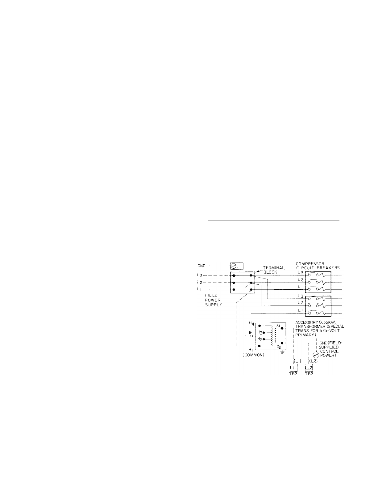
Step 5 — Make Electrical Connections
All field wiring must conform with local code
requirements. Control circuit is 115 volts on all
60-Hertz units. Accessory transformer package is
available to allow 115 volts to be taken directly from
unit terminal block (see Fig. 3). Installation instruc
tions are furnished with the accessory package. Con
trol power may also be supplied from a separate
source thru a 15-amp fused disconnect.
Inside the control box, provision is made to
connect the ground wire which must be installed
with each field power supply.
All units are factory supplied with across-the-line
start at all voltages.
Refer to Table 4 for electrical data on individual
compressors and complete units and compressor
usage.
LABEL DIAGRAMS
The applicable Label Diagrams for the 30H040,
050,060 Heat Reclaim units are the same as for the
standard 30HK040,050,060 units.
Table 3 — Unit Voltage and Model Number
UNIT
30H
200
.....
040 ! 420
050 i 420
060 420 520 I 620 120
*Last 3 digits of complete mode! number.
EQUIP GND
WHEN CONTROL CIRCUIT POWER IS FROM SEPARATE SOURCE
INCOMING WIRES ARE CONNECTED DIRECTLY TO
TERMINALS
CONNECTED TO NEUTRAL (GROUND) POTENTIAL.
CB — Circuit Breaker
EQUIP GIMD — Equipment Ground
TB — Terminal Board
*Appropriate transformer terminal depends on unit voltage,
instructions with accessory transformer package. H2 = 200 v;
H3 = 230 v; H4 = 460 v.
NOTE: For grounding 1 1 5-voit control circuit when transformer is
used, see instructions with accessory transformer package.
LL! AND
: 520 1
LL2
230 i
ON TB2.
VOLTS
Model*
520 ‘
460
620 120
620 > 120
±2 MUST BE
575
Fig. 3 — Wiring Schematic — Unitand Control
Power Supply
Page 5

VOLTS
Nameplate
Supply Range"
UNIT 30 MKW
040 50.4
H 050
060 71.8 259 350
UNIT 30
; 040 250 (2) 25 2 86 345
П L/OU
060 275 (2) 35.9 115 506
61.1 230
COMPR
nctr KW
06 E
275 (L) 35.9 11 5 506
250 (R) 25.2 86 345
MCA
194
RLA LRA ; MTA
Table 4 — Electrical Data; 3-Phase, 60-Hertz
COMPLETE UNIT
200 230 460
180-229
Max
Fuse
Amps
250
300
207-264 414-528
Max Max
MCA
167 225
207 300
239
Fuse MCA
Amps Amps
104
300 120 150 97
84
INDIVIDUAL COMPRESSORS
200 V
; eo..; 74 300
' 80 "
Í" 80" 106 440
230 V
RLA LRA MTA RLA
102
106 440
"i 72
..........
74 300 ; 102 37 150 50 30
1
......
''
72 ' 1 53 220 73 43 176 : 58
575
518-660
Fuse MCA Fuse
110 68 90 B250 B250
150
37 150 50 30 120 42
53 220 73 43 176 58
84
460 V
LRA
Max
Amps
125
125
MTA RLA LRA MTA
06E COMPR
l' (l(^''' 2'{R) /^
I
J275 B250
J275 ; J275
...
575
USAGEt
Cl rcuit
........................
; 120 42
6-Pole Breakers: values shown are for each 3-poie
KW — Maximum Power Input (compressor)
LRA — Locked Rotor Amps
MCA — M inimum Circuit Amps. Complies with National Elec
MKW — Unit Power Input at operating conditions of 50 F Leaving
section.
trical Code (NEC), Section 430-24.
Chilled Water Temperature (44 F Saturated Suction
Temperature) and 145 F Saturated Discharge
Temperature.
ELECTRICAL BOX CONTROL SECTION
Inside this section are: relays, high- and lowpressure cut-outs, low water-temperature cut-out,
timer, terminal strips and a 4-step temperature
controller. On the outside (control panel) are: con
trol circuit ON-OFE switch, partial load switch,
compressor transfer switch, compressor run light,
safety trip lights and control circuit fuse. The control
panel is hinged to provide easy access to the controls
inside.
ELECTRICAL BOX, POWER SECTION
The main electrical power supply is brought in
START-UP AND SERVICE
MTA — Must Trip Amps (Factory-installed circuit breaker)
RLA — Rated Load Amps
*Untts are suitable for use on electrical systems where voltage
supplied to the unit terminals is not below or above the range
limits shown.
fPrefix: B, J = 1 electric unloader.
thru the top of the electrical box, on the left-hand
side (see Fig. 1). The hole is suitable for accommo
dating 3-in. conduit. Pressure-lug connections on
the terminal block are suitable for copper, copperclad aluminum or aluminum wire.
In this section are: main power terminal block,
compressor circuit breakers with calibrated mag
netic trip (for compressor motor overload and
locked rotor protection) and compressor motor con
tactors. The panel over this section is secured with
screws as a safety measure against casual entry for
purposes other than service.
WARNING: Shut off all power to the unit
before proceeding with any service work.
INITIAL CHECK
Do not start the liquid chiller even momentarily
until the following steps have been completed.
1. Check all auxiliary components such as chilled
liquid circulating pump, cooling tower if used,
air handling equipment, or other equipment to
which the chiller supplies liquid. Consult the
manufacturer’s instructions.
2. Check safety thermostat. See Safety
Thermostat.
3. Determine if there is a refrigerant charge in the
system. See Check Refrigerant Charge.
4. Backseat (open) compressor suction and dis
charge shutoff valves.
5. Open liquid line shutoff valves.
6. Fill chilled liquid circuit completely with clean
water or other noncorrosive fluid to be cooled.
Bleed all air out of high points of system.
7. Fill cooling tower for condenser cooling water.
8. Set temperature controller.
9. Check tightness of all electrical connections..
10. Check compressor oil (should be visible in
bull’s-eye). Refer to Check Oil Charge.
11. Be sure crankcase of each compressor is warm
(heaters should be on for 24 hours before
starting compressors).
12. Be sure compressors are floating freely. See
INSTALLATION, Step 3.
Page 6

Check Refrigerant Charge
1MP(.)R'1 \N T; Do not t>pi;n liquid \al\t' or
«-•omprcssor ciisdniiiie \al\o uinil it is deter
mined that there is a charge in the remainder of
the system. .1 ¡h‘.sin\i- /ircs'.urc u;// induuh' a
iharj^f m ¡hi' siv/iv//
The units are shipped with a full refrigerant
charge (see Table 2). However, if it is necessary to
add refrigerant, the unit should be operated for
some time at full capacity and then charge can be
added until the sight glass is clear of bubbles. For
maximum liquid subcooling, the liquid level should
be up to the liquid level test cock located on the
shell, near the end, of each tower condenser. This
usually requires additional refrigerant charge
beyond the amount to clear the sight glass (see
LIQUID CHARGING METHOD).
If there is no refrigerant vapor pressure in the
system, the entire system must be leak tested. After
repair of leaks, the system must be evacuated before
recharging. See Standard Service Techniques
Manual, Chapter 1, Refrigerants, for leak testing,
evacuation and charging procedures.
C.M.' nON; When adjusting rdrigerant charge.
Circulate water thru the condenser and cooler at
ail times to prevent frec/ing. Frec/ing damage is
considered abuse and is not covered by Carrier
warrants.
The liquid charging method is recommended for
complete charging or when additional charge is
required.
LIQUID CHARGING METHOD
C.\U i'lON; Be careful not to overcharge s\stem. Oserchaigmg results in higher discharge
pressure with higher cooling water consurnp-
tion, possible compressor damage, higher power
consumption.
Charge thru I / 4-in. flare connection on liquid line
shutoff valve. Never charge liquid into the low-
pressure side of the system.
1. Frontseat (close) liquid line shutoff valve.
2. Connect a refrigerant cylinder loosely to charg
ing valve connection. Purge charging line and
tighten connections.
3. Open liquid line shutoff valve.
4. If system has been dehydrated and is under
vacuum, break vacuum with refrigerant (gas
charge). Build up system pressure to 58 psi for
R-22 (32 F). Invert refrigerant cylinder so that
liquid refrigerant will be charged.
5. a. For complete charge, see “Charging” in
Standard Service Techniques Manual, Chap
ter 1, Refrigerants. Follow Charging By
Weight procedure. (When charge is nearly
full, complete process by observing sight glass
for clear liquid flow.)
b. For complete charge where refrigerant
cylinder cannot be weighed, or for adding
refrigerant, follow the procedure Charging
By Sight Glass in the manual.
6. To ensure maximum subcooler performance,
check liquid level in tower condensers by means
of test cock located on each condenser shell near
right end tube sheet. Liquid discharge from test
cock indicates fully charged subcooler.
Check Oil Charge — All units are factory charged
with oil. If oil is visible in sight glass, check the unit
for operating readiness as described in the section,
Initial Check; then start compressor. Observe level
and add oil, if required, to bring level in erankcase
! / 8 to 3/ 8^ of bull’s-eye during steady operation. To
add or remove oil, see Standard Service Techniques
Manual, Chapter 1, Refrigerants.
Use only Carrier approved compressor oil. Do
not reuse drained oil or use any oil that has been
exposed to atmosphere.
Approved compressor oils:
Sun Oil Co. Suniso 3GS
Texaco, Inc. Capella BI
E.I. DuPont Co. DuPont Synthetic Refrig
eration Oil, 150 SSU only
TO ADD OIL
Close suction shutoff valve and pump down
crankcase to 2 psig (low-pressure cutout must be
bypassed with a jumper). Wait a few minutes and
repeat as needed until pressure remains at 2 psig.
Close diseharge shutoff valve. Remove oil fill plug
above bull’s-eye, add oil thru plug hole and replace
plug. Reopen suction and discharge valves. Run
compressor for about 20 minutes and check the oil
level.
TO REMOVE OIL
Pump down eompressor to 2 psig. Close suetion
and discharge valves. Loosen the 1/4-in. pipe plug
in compressor base and allow the oil to seep out
past the threads of the plug. The crankcase will be
under slight pressure. Be careful not to remove the
plug; the entire oil charge may be lost. Small
amounts of oil can be removed thru oil pump dis
charge connection while compressor is running.
START-UP AND OPERATION CHECKS
Start-up should be performed only under super
vision of experienced refrigeration mechanic. Be
sure crankcase heaters have been energized for 24
hours.
1. Open all system valves that may have been
closed during or after charging.
2. Check air-handling equipment, chilled water
and condenser water pumps, and any other
equipment eonneeted to chiller.
3. Start unit by firmly pushing ON button.
4. Check all controls for proper operation.
Page 7

5. Check leaving chilled water temperature to see
that it remains well above freezing.
6. Recheck compressor oil level (see Check Oil
Charge).
7. Be sure unit is fully charged (see Check Refrig
erant Charge).
Check Refrigerant Feed Components
THERMOSTATIC EXPANSION VALVE (TXV)
One valve for each refrigerant circuit is used to
control the flow of refrigerant. The valve is
activated by a temperature sensing bulb clamped to
the suction line. The valve is factory-set to main
tain a superheat of 8 F to 10 F. Do not change setting
unless absolutely necessary.
FILTER-DRIER (replaceable core type)
The function of the filter-drier is to maintain a
clean, dry system. The moisture indicator (below)
can indicate any need to change the filter-drier.
Additional pressure-relief valves, properly
selected, must be field installed to protect fieldinstalled high side equipment as may be required by
applicable codes.
A fusible plug is factory installed on each suction
line for low-side protection. This plug will relieve
on temperature rise to 170 F.
Most local codes require that a relief valve be
vented directly to outdoors. The vent line must not
be smaller than the size of the relief valve outlet.
Check Compressor Protection Devices
CIRCUIT BREAKER
Each compressor is protected against an overcurrent condition by a manual-reset calibrated-trip
circuit breaker.
iMi*i)R ! \N T; i)n not b\ pa>v connections or
increase the size ot i.nc breaker to ct.'rrcci
trouble. Determine the cause and correct before
resetting breaker.
MOISTURE-LIQUID INDICATOR
The indicator is located immediately ahead of the
TXV to provide a constant indication of the
moisture content of the refrigerant. It also provides
a sight glass for refrigerant liquid. Clear flow of
liquid refrigerant indicates sufficient charge in the
system. Bubbles indicate under-charged system or
presence of noncondensables. Moisture in the sys
tem, measured in parts per million (ppm), will
change color of indicator.
Unit must be in operation at least 12 hours before
moisture indicator will give an accurate reading.
With unit running, indicating element must be in
contact with liquid refrigerant to give true moisture
indication.
At the first sign of moisture in the system, change
the filter-drier. The color BLUE indicates a safe,
dry condition and PINK shows that a dangerous
moisture level is present. The first sign of moisture
would be a LIGHT VIOLET color.
LIQUID LINE SERVICE VALVE
This valve provides a refrigerant charging port
and, in combination with the compressor discharge
service valve, allows the refrigerant to be pumped
into the high side.
PRESSURE RELIEF DEVICES
A high-side pressure-relief valve is factory in
stalled on each tower condenser. The valve is set to
open at a maximum pressure of 385 psig (maximum
design working pressure of the condenser).
DISCHARGE TEMPERATURE
THERMOSTAT
A sensor in the discharge side of each com
pressor reacts to excessively high discharge gas tem
perature and shuts off the compressor. The high
discharge gas temperature is a direct indication of
an overtemperature condition in the motor
windings.
CRANKCASE HEATER
The heater in each compressor prevents absorp
tion of liquid refrigerant by the oil when the
compressor is not operating.
CM ! ION; 1 :ie licalc;'. wisich is held ;n place
by a bracket, must be tight to prevent it from
backing out of the crankcase. The heater will
burn out if exposed to air for an extended time.
Each 125-watt electric heater is wired into the
115-volt control circuit thru the normally closed
contacts of the control relay in such a way that it is
energized only when the compressor is not
operating.
C.\i. • ¡ON. Never ope:; any svUten or discon
nect that -Aill de-encrei/c the crankcase heater
unlcs.s the unit Is being serxiced or will be shut
down for a proic-nged period. Alter such ser\ ice
or prolonged shutdown, cnergi/c the crankcase-
heater for 24 hours before starting the
comnrcssor.
TIME GUARD® CONTROL
This control protects the compressor against
short cycling (switch A on four-function timer).
Page 8

FOUR FUNCTION TIMER
Refer to Fig. 4 — Timer Cycle. The functions are
as follows:
Switch A (Contacts A-Al, A-A2) runs the timer
motor. This provides a minimum of 5-1/2 minutes
after the compressor stops before it can restart, to
prevent short cycling (Time Guard® control).
Switch B (Contacts B-Bl, B-B2) provides 1-second
time delay for part-winding start and also provides a
lock-out function.
Switch D (Contacts D-D 1) provides a 2-1 / 2 minute
bypass of the low-pressure switch at start-up to
prevent nuisance trips under cold-start conditions.
Switch E (Contacts E-El) provides a 35-second
bypass of the oil safety switch (OPS) at compressor
start-up (when OPS is used). If sufficient oil pressure
does not build up in this time, the compressor stops.
CAUTION; Do not attempt to restart the com
pressor for a second time until the problem has
been determined and corrected.
f
REMOVE ORANGE WIRE
0 OR 8 MIN,
NOTE: black DENOTES CLOSED CONTACTS
POSITION DURING UNIT OPERATION,
!
------
2-6 SEC 1
--------------------- 150 SEC^-^
----------------
!
DD2 1
—+ -55 MIN-
Fig. 4 Timer Cycle
OIL PRESSURE SAFETY SWITCH (OPS)
This control is available as an accessory. Refer to
Fig. 5 for field wiring connections.
The pressure switch is factory set at the following
pressures and should not be adjusted in the field:
SWITCH POSITION
Close on rise
Open on fall
PRESSURE SETTING
9-12 psi diff
4- 6 psi diff
OPS — Oil Pressure Safety Switch
TB — Terminal Board
Fig. 5 — Oil Pressure Safety Switch to Control
Box Wiring Connections
Check Unit Safety Devices
SAFETY THERMOSTAT (Fig. 6)
This low water temperature cutout (LWTC) pro
tects the unit against freeze-up due to operating
malfunction. The sensing bulb is inserted into a well
located in the leaving water nozzle. As installed, the
standard control is factory set to open at 36 ±2 F,
breaking the control circuit and locking out the unit.
The contacts remake at 5 + 2 F above the cutout
point, but the control circuit switch must be pressed
to OFF and then to ON for unit restart. This action
reenergizes the control circuit and starts the timer
under Time Guard® control.
The thermostat is designed to cut out in a range
down to -30 F, but to obtain this range, the low-limit
stop tab on the underside of the dial must be either
cut or bent. Make this adjustment only if necessary
(when cooling glycols or brines).
n u LOW LIMIT STOP TAB
The oil pressure safety switch is wired in parallel
with Switch E of the 4-function timer. This arrange
ment allows approximately 35 seconds for oil
pressure to reach normal operating level after com
pressor start. If the oil safety switch does not close
within 35 seconds, the compressor shuts down.
To restart the compressor, the control circuit
ON-OFF switch must be pressed to OFF and then to
ON. The timer will start and after approximately
5.5 minutes the compressor will start. If normal oil
pressure is established within the next 35 seconds,
the compressor continues to run. If, however, the oil
pressure does not reach a safe level, the compressor
stops at the end of the 35 seconds and locks out.
Fig. 6 — Safety Thermostat
(No. HH22CC050 Shown)
Page 9

HIGH-PRESSURE SWITCH (HPS)
The HPS settings are nonadjustable. Table 5
shows the factory settings for this switch.
If the HPS cuts out while the unit is in normal
operation (2-1/2 minutes or more after compressor
start-up), the compressor will stop and lock out. To
restart the compressor, the ON-OFF control circuit
switch must be manually pressed to OFF and then to
ON. The timer will start, and after approximately
5.5 minutes, the compressor will start under Time
Guard control. If the pressure has not dropped to
the HPS cut-in point (see Table 5), the compressor
will stop again immediately and again lock out. No
further attempts to restart should be made untd the
trouble is found and corrected. Unless the control
circuit switch is pressed to OFF at this time, the
timer will continue to run for approximately 1-1/2
minutes and then stop.
If the control circuit switch is left at ON, the
control circuit remains partially energized, includ
ing the timer relay. Consequently, if the pressure
drops to the HPS cut-in point before restart, the
compressor overtemperature protector (COP) light
will come on. This should not be cause for alarm in
this case since the light is functional only when the
discharge temperature thermostat contacts open
during normal unit operation.
:ì
RANGE ADJ SCREW
TURN CLOCKWISE TO RAISE BOTH CUT-IN
AND CUT0UT(7PSI PER TURN),
LPSl
г
(RIGHT SIDE OF CONTROL BOX, VIEWED FROM TOP)
DIFFERENTIAL ADJ SCREW
TURN CLOCKWISE TO DECREASE
(8 PSI PER TURN). ONLY CUTOUT CHANGES
/
LPS2
pressor start-up), the timer starts and runs for
approximately 5.5 minutes. The compressor then
starts, bypassing the LPS for 2-1/2 minutes under
Time Guard® control. If the LPS cut-in pressure is
reached within the 2-1/2 minutes, the compressor
continues to run; if the required pressure has not
built up, the compressor stops at the end of the 2-1/2
minutes and locks out.
Further attempts to restart the unit must not be
made until the trouble has been found and cor
rected. The LPS contacts must be closed before the
compressor can be restarted after lockout.
Check Capacity Control System
DESCRIPTION
Capacity control is a system which loads and
unloads compressor cylinders and starts and stops
the compressors to maintain load requirements. The
system includes a 4-step temperature controller
and cylinder unloaders (see Table 2). Table 6 shows
the capacity control steps.
Table 6 — Capacity Control Steps
SEQUENCE 2
f
Oper Cyl
Cap. j Tot.
50 i 4
20 : 2
60 : 6
80 ^ 8
100 10
33 1 4
67 Ì 8 4 4
Ckt i Ckt
1 1 2
— i
2
2 ! 2
^ ! 2
4 : 2
4 i 4
6 i 4
— i 4
4 : 6
UNIT CONTR
ЗОН
STEPS
1
040
050
060
2 50 4 2 ; 2
3 75 6 4 : 2 75 6 2 1 4
4
1
2 60 6
3
4 100
1
2
3 83 10 6 Ì 4 83 1 10
4
SEOUENCE1
%
Cap.
25 2
100
40
80
33
67 8
100
Oper Cyl
Ckt Í Ckt
Tot.
1 1 2
2 i — 25 i 2
8 4 ; 4 100 : 8 4 ; 4
4 4 : —
4 , 2
6 ; 2
8
6 i 4
10
4 4 : —
4 : 4
12 6 1 6 100 ! 12 6 ) 6
Fig. 7 — Low-Pressure Switch (LPS)
Adjustment
Table 5 — Pressure Switch Specifications
UNIT
PRESSURE
RANGE (psig)
DIFFERENTIAL
SETTING (psi)
FACTORY
SETTING (psig)
High Fixed
Low 10 to 90 Adjustable
High 103 ±19 (Fixed)
Low
High
Low 29 ±4 1 44 ±4
TOW-PRESSURE SWITCH (EPS)
The EPS is bypassed for 2-1/2 minutes after
compressor start on all start-ups.
The EPS has an adjustable range from 10 to 90
psig and a differential of 13 to 50 psi. Table 5 shows
the factory settings for this switch.
If the LPS cuts out while the unit is in normal
operation (any time after 2-1/2 minutes from com
зон
13 to 50 Adjustable
Cutout Cut-in
335 ±10 —
4-STEP TEMPERATURE CONTROLLER
This controller consists of 4 load switches
actuated by pressures developed in a temperature
sensing bulb located in the return water line of the
chilled water system. The controller is factory set to
control from return water temperature thru a cool
ing range of 10 F. The sequence switches are
factory calibrated and sealed and should not require
any field changes.
I MPtJR I .AN I: If a different return-water cool
ing range or lea\'in^-\\.atcr control is specified,
or if brine below 10 F'i.s to be used, the controller
must be changed. Consult local Cai’rier rep
resentative for proper control device.
The return water temperature at which the last
step of capacity unloads is indicated by the leaving
water temperature design setpoint on the adjustable
dial (Fig. 8).
Page 10

Example;
Design setpoint is at 44 F. On a reduction in load,
the capacity of the unit will be reduced to zero
when return water temperature drops to 44 F, and
unit will cycle off.
WARNING: Any alteration of factory settings,
except design setpoint, without Carrier authori
zation, may void the Carrier warranty.
DESIGN SETPOINT ADJUSTMENT
When unit is ready for operation, insert small
screwdriver in adjusting slot (Fig. 8) and rotate to
turn dial (dial may also be turned by hand). Rotate
until the design setpoint for the installation appears
directly under the pointer. Insert a thermometer in
the return chilled water connection and allow the
unit to run thru a cycle. At the instant the last step of
capacity unloads (switch no. J opens), read the tem
perature. If it is not the same as the dial reading, the
variation can be compensated by shifting the control
point slightly.
('.•\l 'IK;N: Do not force the dial past the stop.
This could cause loss of the control point and
damage the instrument.
/ ■. '
ADauSTtNS
SLOT.
LEAVING
WATER
TEMP(F)
DESIGN
CALIBRATED «AL
POINTER
STOP
Fig. 8 — Setpoint Adjustment
CYLINDER UNLOADING SYSTEM
Each unloading device is of the cylinder head
bypass type and unloads 2 cylinders when operating
solenoid is energized. Cylinder unloaders are ener
gized and de-energized by load switches in the
temperature controller.
Steps under Cylinder Bank Loaded and Cylinder
Bank Unloaded refer to numbered callouts on
Fig. 9 and 10.
Cylinder Bank Loaded (Fig. 9)
1. With solenoid valve not energized, gas bypass
port is closed by solenoid valve stem.
2. Discharge manifold pressure extends thru the
strainer and bleed orifice into solenoid valve
stem chamber and behind bypass piston.
3. Refrigerant pressure overcomes bypass valve
spring pressure and forces piston forward closing
the bypass from the discharge manifold to the
suction manifold.
4. Cylinder bank discharge pressure forces open the
discharge piston check valve. Refrigerant gas
enters the discharge manifold.
As long as the solenoid valve is not energized, the
cylinder bank will continue to operate fully loaded.
,, i
Fig. 9 — Cylinder Bank Loaded
Cylinder Bank Unloaded (Fig. 10)
1. When solenoid valve is energized, gas bypass port
is opened by solenoid valve stem.
2. Discharge manifold pressure extends into sole
noid valve stem chamber and behind bypass
piston.
3. Open gas bypass port allows pressure to bleed
into suction manifold causing reduction of pres
sure behind bypass piston.
4. When bypass valve spring pressure overcomes
gas pressure behind piston, the piston moves
back, opening bypass from discharge manifold to
suction manifold.
5. Cylinder discharge pressure on face of check
valve piston is reduced and discharge manifold
pressure closes check valve. The cylinder bank is
now isolated from discharge manifold.
As long as solenoid valve is energized, cylinder
bank will operate fully unloaded.
Discharge
FlSTON
CHECK VALVE
ASSEMBLY
DISCHARGE
MANIFOLD
Fig. 10 — Cylinder Bank Unloaded
f
10
Page 11

UNIT OPERATION
Control Power (115 volts) can be from a separate
source, thru a 15-amp fused disconnect or can be
taken from the main unit power source, thru a field-
supplied transformer as shown on the wiring label.
Control Sequence — At initial start-up, assume
all safety devices are satisfied and the chilled water
temperature controller switches are all in position
for maximum cooling capacity.
Close the compressor circuit breaker and press the
control circuit ON-OFF switch to ON. Timer no. 1
starts and, depending on the position of the timer,
compressor no. 1 starts in approximately 12 seconds
to 8 minutes. At compressor start-up, the D-D 1 con
tacts (see Four-Function Timer and Fig. 4) are
closed, bypassing the low-pressure switch for 2-1/2
minutes. In addition, the E-El contacts are closed,
bypassing the oil safety switch (if used) for approxi
mately 35 seconds. Both these bypass functions are
protection against the compressor continuing to run
under conditions that could cause damage to the
compressor. Barring any malfunction, when the
timer contacts A-A2 close, approximately 2-1/2
minutes after start-up, timer no. I stops and timer
no. 2 starts. In approximately 12 seconds to 8 min
utes, compressor no. 2 starts. Timer no. 2 completes
the same cycle as timer no. ! and stops. Unit is now
in normal operation, with both compressors
running.
The temperature controller regulates the cooling
capacity by loading and unloading compressor cyl
inders and stopping and starting the compressors
under Time Guard® control, in response to load
requirements.
Complete Unit Stoppage and Restart — After
each possible cause for unit stoppage is a short
description of the normal method of restart.
1. CONTROL POWER INTERRUPTION (IN
CLUDES BLOWN FUSE).
After power is restored, or fuse replaced, restart
is automatic thru normal timer cycle.
2. CONTROL CIRCUIT ON-OFF SWITCH IS
OPENED.
When the switch is opened, the timer motor starts
automatically, runs for approximately 5-1/2
minutes and stops. To restart, press ON-OFF
switch to ON. In approximately 12 seconds, com
pressor starts.
3. CONTACTS OF ANY AUXILIARY INTER
LOCK ARE OPEN.
After trouble has been corrected, restart is auto
matic thru normal timer cycle.
4. LOW WATER TEMPERATURE CUTOUT
CONTACTS ARE OPEN.
Allow water temperature to rise 5 F; then press
control circuit ON-OFF switch to OFF and back
to ON. This restarts the timer. Unit restarts auto
matically thru normal timer cycle.
5. CONTROL CIRCUIT FUSE BLOWS.
Check for possible cause; then replace fuse. Re
start is automatic thru normal timer cycle.
6. CHILLED WATER FLOW STOPS.
Locate and correct cause. When water flow
resumes, unit restart is automatic thru normal
timer cycle.
Individual Compressor Stoppage and Restart
1. LOW-PRESSURE SWITCH (LPS) OPENS.
Reset and restart are automatic, thru normal
timer cycle, unless refrigerant charge is very low
or lost. In this case, increase the charge to
normal level before restart.
2. HIGH-PRESSURE SWITCH (HPS) OPENS.
Press RESET button to reenergize the open
circuit. Restart is thru normal timer cycle.
3. DISCHARGE TEMPERATURE SWITCH
OPENS.
Press RESET button to reenergize the open
circuit. Restart is thru normal timer cycle.
4. OIL PRESSURE SAFETY SWITCH OPENS.
Press RESET button to reenergize the open
circuit. Restart is thru normal timer cycle.
IMPORTANT: If stoppage by a safety device
repeats once, do not attempt another restart
until the cause is determined and corrected.
Refer also to the Troubleshooting section for
additional information on unit malfunctions.
SERVICING THE COOLER
When the cooler heads and partition plates are
removed, the tube sheets are exposed showing the
ends of the tubes as seen in Fig. 11. Four tubes in
the bundle are secured inside the cooler at the
baffles and cannot be removed. These are identified
on the tube sheets by a drill mark horizontally
adjacent to each of the 4 tubes. If leakage occurs in
any of these 4 tubes, plug the tube as described under
Tube Plugging.
‘Four fixed tubes (cannot be removed) identified by adjacent
drill points.
Fig. 11 — Typical Tube Sheet
11
Page 12

Tube Plugging — A leaky tube(s) can be plugged
until retubing can be done. The number of plugged
tubes determines how soon the cooler must be
retubed. If several tubes require plugging, check
with your local Carrier representative to find out
how the number and location will affect unit
capacity.
Figure 12 shows an Elliot tube plug and a crosssectional view of a plug in place. Table 7 lists the
components for plugging.
C.MJ I'lON; Use extreme care when installing
plugs to prevent damaging the tube sheet sec
tions between the holes.
Clean parts with Loequie “N” and apply a few
drops of Loctite #75 to obtain a tight seal without
using too much force to set the pin.
Usually plugs can be removed by heating the pro
jecting end of the pin to approximately 1000 F and
chilling quickly with water. Apply the heating
flame to the side of the pin to prevent overheating
the tube sheet.
Retubing (see Table 7) — When retubing is to be
done, obtain the service of qualified personnel,
experienced in boiler maintenance and repair. Most
standard procedures can be followed, except that
for the tubes in the ЮНА coolers, a 5% crush is
recommended in setting torque control (5/8-in.
diameter tubes are used in these coolers).
Example;
a. Tube sheet hole diameter
b. Tube OD
...................................................................
c. Clearance (a minus b)...............................................005 in.
d. Tube ID before rolling
(Use Elliot tube gage)................................................551 in.
e. 5% of twice the wall thickness
(5% of b minus d)
f. Tube ID after rolling
(c + d + e)...................................................................560 in.
.........................................
.....................................................
630 in.
625 in.
004 in.
Table 7 — Plugs and Tubes
UNIT зон
PLUGGING
For Tubes
Brass Pin
Brass Ring
For Holes without Tubes
Brass Pin
Brass Ring
Loctite
Loequie
TUBE DATA
Part No.
Length (in.)
OD (in.)
Wall Thickness (in.)
Plain End
Finned Section
*Order directly from Elliot Co.
Lagonda Operation
Springfield, Ohio
fCan be obtained locally.
040
PART NUMBER
853103-500*
853002-559*
853103-1*
853002-631*
SPECIFICATION
10HA501043
74.50
0.625
0.037
0.025
050, 060
No. 75f
"N”t
10HA501053
85.50
0.625
0.037
0.025
Tightening Cooler Head Bolts
GASKET PREPARATION
When reassembling, use new gaskets. Com
pressed asbestos/neoprene gaskets. Carrier
Material Specification ZAOO-24, are to be momen
tarily dipped in compressor break-in oil prior to
assembly. Gaskets are not to be soaked in oil as
gasket deterioration results. Dipped gaskets are to
be used within 30 minutes to prevent deterioration.
BOLT TORQUES
The following torques are to be applied during
the bolt tightening sequence described below:
5/8-in. diameter flange bolts.... 150 - 170 Ib-ft
1 / 2-in. diameter center-stud nuts and
1 / 2-in. diameter flange bolts
.......................
70 - 90 Ib-ft
>0 A
TUBE SHEET
Fig. 12 — Elliott Tube Plug
12
Page 13

BOLT TIGHTENING SEQUENCE (Fig. 13)
The following is a recommended bolt tightening
sequence:
Step 1 — Tighten moderately (without torquing) all
the flange bolts in the sequence shown.
Step 2 — Tighten moderately (without torquing) the
hex nuts on the center studs (no specified sequence).
Step 3 — Repeat Step 1, tightening the bolts to the
specified torque.
Step 4 — Repeat Step 2, tightening the nuts to
the specified torque.
Step 5 — Not less than one hour later, retighten the
center stud nuts to the specified torque.
TOP
Fig. 13 — Bolt Tightening Sequence
13
Page 14

SYMPTOMS
Compressor does not run
Compressor cycles on lowpressure control
Compressor loses oil
Frosted or sweating suction fine
Compressor cycles on lowpressure control
Compressor cycles on highpressure control
Unit operates long or
continuously.
TROUBLESHOOTING GUIDE
PROBABLE CAUSE
Power line open
: Control circuit breaker tripped
Safety tripped
Tripped power breaker
Condenser circulating pump not
running
■ Loose terminal connection
Improperly wired controls
’ Low line voltage
Compressor motor defective
Seized compressor
Low-pressure control erratic in
action
Compressor suction valve leaking
I Compressor suction shutoff vaive
partially closed
Low refrigerant charge
Leak in system
Mechanical damage (blown piston
or broken discharge valve)
Oil trapped in line
Crankcase heaters not energized
: during shutdown
Expansion vaive admitting excess
refrigerant
Plugged compressor suction
strainer
High-pressure control erratic
in action
Compressor discharge valve
partially closed.
Air in system
Condenser scaled
Condenser water pump orfans not
operating
Low refrigerant charge
Control contacts fused
Air in system
Partially plugged or plugged
expansion valve or strainer
Defective insulation
Service load too high
Inefficient compressor
REMEDY
Check fused disconnect. Replace
fuse if blown^
Check control circuit for ground or
short.
Reset breaker.
Reset.
Check the controls. Find cause of
trip and reset breaker.
Power off — restart.
Pump binding — free pump.
Incorrect wiring — rewire.
Pump motor burned out — replace.
Check connections.
Check wiring and rewire.
Check line voltage — determine
location of voltage drop and
remedy deficiency.
Check motor winding for open or
short. Replace compressor, if
necessary.
Replace compressor.
Raise differential setting.
Check capillary for pinches.
Replace control if defective.
Replace valve plate.
Open valve.
Add refrigerant.
Repair leak.
Repair damage or replace
compressor.
Check piping for oil traps.
Check wiring and crankcase
heater relay. Replace heater if
necessary.
Adjust expansion vaive. Replace
valve if defective.
Clean strainer or replace.
Check capillary tube for pinches.
Set control as required.
Open valve, or replace if defective.
Purge.
Clean condenser.
Start pump — repair or replace if
defective.
Add refrigerant.
Replace control.
Purge.
Clean or replace.
Repair or replace.
Keep doors and windows closed.
Check valves, replace if necessary.
........................
............
......
14
Page 15

TROUBLESHOOTING GUIDE (Coni)
SYMPTOM
System noises
Chattering unloader
Freeze-up
Hot liquid line
Frosted liquid line
Compressor will not unload
Compressor will not load
High suction
PROBABLE CAUSE
Piping vibration
Expansion valve hissing
Compressor noisy
Stuck check valve in valve plate
Improper charging
■ Improperly set safety thermostat
Operating with safety thermostat
bypassed
Improper circulation of chilled
water
System not drained for winter
shutdown
: Shortage of refrigerant due to leak
: Expansion valve opens too wide
Receiver shutoff valve partially
closed or restricted.
Restricted filter-drier
Burned out coil
Leaky bypass piston
Stuck needle valve
Miswired solenoid
plugged bypass port (low side)
Weak bypass piston spring
Damaged bypass piston
Stuck needle valve
i Miswired solenoid
Plugged bypass port strainer
(high side)
Stuck check valve in valve plate
REMEDY
Support piping as required.
Check for loose pipe connectors.
Add refrigerant.
Check for plugged liquid line
strainer.
Check valve plates for valve noise.
Replace compressor (worn
bearings).
Check for loose compressor hold
down bolts.
Examine check valve components,
clean or replace as necessary.
Make sure that a full quantity of
water is flowing thru the cooler
while charging and that suction
pressure in cooler is equal to or
greater than that corresponding to
32 F (58 psig for Refrigerant 22).
Check safety thermostat for proper
setting at beginning of each
season.
if thermostat was bypassed for
checking, be sure it is back in the
circuit before starting the unit.
Use ample size cleanable strainer
in the chilled water circuit. Make
sure strainer is clean. It may some
times be necessary to chemically
treat the water to prevent forma
tion of deposits.
Be sure and remove drain plugs at
end of cooling season. Blow out
any residual water. Instead of
draining, a suitable antifreeze may
be added to the water. Damage to
the chiller due to freezing is con
sidered abuse and is not covered
by the warranty.
Repair leak and recharge.
Adjust expansion valve.
Open valve or remove restriction.
Remove restriction or replace
filter-drier core.
Replace coil.
Clean or replace.
Clean.
Wire correctly.
Clean.
Replace.
Replace.
Clean.
Wire correctly.
Clean.
Examine check valve components,
clean or replace as necessary.
15
Page 16

For replacement items use Carrier Specified Parts.
Manufacturer reserves the right to discontinue, or change at any time, specifications or designs without notice and without incurring obligations.
Book 2
Tab
Form 30H-1 SI New
5c
Printed in U.S.A, 10-79
PC 111 Catalog No. 533-079
 Loading...