

Carpigiani 193 SP USA Installation Manual

INSTRUCTION HANDBOOK
193 SP/USA G
193 SP/USA G
We wish to thank you for the preference granted to us by purchasing one of
CARPIGIANI machines.
To the best guarantee, since 1993 CARPIGIANI has submitted its own Quality
System to the certifi cation according to the international Standard ISO 9001,
nowadays its production has got UNI-EN-ISO 9001:2008 Certifi ed Quality
System.
Moreover, CARPIGIANI machines comply with following European Directives:
- “Machinery” Directive 2006/42/EC,
- “Low Voltage” Directive 2006/95/EC,
- “EMC” Directive 2004/108/EC,
- “PED” Directive 97/23/EC,
- Regulation 2004/1935/EC relating to “Materials and articles in contact with foodstuffs”
CARPIGIANI
Via Emilia, 45 - 40011 Anzola dell'Emilia (Bologna) - Italy
Tel. +39 051 6505111 - Fax +39 051 732178
This manual contains a TRANSLATION OF THE ORIGINAL INSTRUCTIONS and may not
be reproduced, transmitted, transcribed, fi led in a data retrieval system or translated into other
languages, without the prior written permission of CARPIGIANI.
The purchaser has the wright to reprint it for his own offi ce use.
CARPIGIANI policy pursues a steady reasearch and development, thus it reserves the right to
make changes and revisions whenever deemed necessary and without being bound to previous
statements to the purchaser.
Edition: 01 Date: 2011/05
Editor: AM Verifi ed: LP Approved: RV
193 SP USA G_EN - 2011/05 - Ed. 01
Modifi cations:
- 2 -

GENERAL INDEX
SECT. FOREWORD
INSTRUCTION HANDBOOK .....................................................................................5
PURPOSE ......................................................................................................................5
HANDBOOK STRUCTURE ........................................................................................5
ADDITIONAL DOCUMENTATION ...........................................................................5
CONVENTIONAL SYMBOLS ....................................................................................6
SYMBOLOGY QUALIFICATION OF THE STAFF ...................................................6
SAFETY ........................................................................................................................7
WARNING ....................................................................................................................7
SECT. 1 - GENERAL INFORMATION
1.1 GENERAL INFORMATION .....................................................................................9
1.1.1 MANUFACTURER’S IDENTIFICATION DATA ............................................9
1.1.2 INFORMATION ABOUT SERVICE ................................................................9
1.1.3 INFORMATION TO THE USER ......................................................................9
1.2 INFORMATION ABOUT THE MACHINE .............................................................9
1.2.1 GENERAL DATA ..............................................................................................9
1.2.2 MACHINE LAYOUT ........................................................................................10
1.2.3 TECHNICAL FEATURES ................................................................................10
1.2.4 MACHINE SETS LOCATION .........................................................................11
1.3 INTENDED USE .........................................................................................................11
1.4 NOISE ...........................................................................................................................11
1.5 STORING A MACHINE .............................................................................................11
1.6 DISPOSAL OF PACKING STUFFS..........................................................................11
1.7 WEEE (Waste Electrical and Electronic Equipment) .............................................11
193 SP/USA G
SECT. 2 - INSTALLATION
2.1 ROOM NECESSARY TO THE MACHINE USE ....................................................13
2.2 MACHINE WITH AIRCOOLED CONDENSER ....................................................13
2.2.1 AIRFLOW ..........................................................................................................13
2.3 MACHINES WITH WA TERCOOLED CONDENSER ..........................................14
2.3.1 WATER VALVE ADJUSTMENT ......................................................................14
2.4 ELECTRIC CONNECTION ......................................................................................14
2.4.1 REPLACEMENT OF POWER SUPPLY CORD ..............................................14
2.5 REFILLING .................................................................................................................14
2.6 MACHINE TESTING .................................................................................................14
SECT. 3 - DIRECTION FOR USE
3.1 MACHINE CONFIGURATION ................................................................................15
3.2 ELECTRONIC CONTROL KEYBOARD AND BUTTON FUNCTIONS ...........16
3.3 SPIGOT HANDLE ......................................................................................................19
3.4 FEEDING NEEDLE....................................................................................................19
3.5 PRELIMINARY OPERATIONS, WASHING AND SANITIZING........................20
3.6 STARTING THE MACHINE .....................................................................................20
3.7 PRODUCTION ............................................................................................................20
3.8 PASTEURIZATION ....................................................................................................21
3.9 OPENING PROCEDURES ........................................................................................21
3.9.1 SANITIZATION OF THE LID AREA ..............................................................21
3.9.2 DISASSEMBLY AND CLEANING OF COMPONENTS................................21
3.9.3 REASSEMBLY OF COMPONENTS ...............................................................21
3.9.4 EXTERNAL CLEANING OF THE MACHINE ...............................................22
3.10 CLOSING PROCEDURES ........................................................................................22
3.10.1 PREPARE THE MACHINE FOR A PASTEURISATION CYCLE ..................22
3.10.2 DISASSEMBLY AND CLEANING OF THE TANK COVER .........................22
3.10.3 CLEANING THE TANK ZONE ...................................................................... 22
- 3 -
193 SP USA G_EN - 2011/05 - Ed. 01

193 SP/USA G
3.10.4 DISASSEMBLY AND CLEANING THE DRIP DRAWERS ..........................22
3.10.5 SANITIZATION OF THE LID AREA ..............................................................22
3.10.6 CLEANING AND SANITISATION OF THE DRIP TRAY ..............................22
3.10.7 EXTERNAL CLEANING OF THE MACHINE ..............................................22
3.11 ALARMS ......................................................................................................................23
3.11.1 BLACKOUT ...................................................................................................... 25
3.12 PROGRAMMING FOR THE USER .......................................................................26
SECT. 4 - SAFETY DEVICES
4.1 SAFETY SYSTEMS ON THE MACHINE ...............................................................27
SECT.5 - CLEANOUT DISASSEMBLING AND REASSEMBLING OF
PARTS IN CONTACT WITH THE PRODUCT
5.1 HOW TO USE XSAN DETERGENT/SANITIZER ................................................29
5.2 PROGRAMMED CLEANING TIME .......................................................................30
5.3 DRAINING AND CLEANING...................................................................................30
5.4 DISASSEMBLING FEEDING NEEDLE ................................................................30
5.5 DISASSEMBLING THE TANK MIXER..................................................................31
5.6 DISASSEMBLING FRONT LID ...............................................................................31
5.7 DISASSEMBLING OF THE BEATER .....................................................................32
5.8 WASHING AND SANITIZING COMPONENTS ....................................................32
5.9 REASSEMBLING THE TANK MIXER ...................................................................32
5.10 REASSEMBLING THE FEEDING NEEDLE ........................................................33
5.11 REASSEMBLING THE BEATER ............................................................................33
5.12 REASSEMBLING FRONT LID ................................................................................33
5.13 SANITIZING THE WHOLE MACHINE ................................................................34
5.14 PRIMING THE MIX PUMP ......................................................................................34
SECT. 6 - MAINTENANCE
6.1 SERVICING TYPOLOGY .........................................................................................35
6.2 WATERCOOLING .....................................................................................................36
6.3 AIRCOOLING.............................................................................................................36
6.4 TABLE OF SPARE PARTS EQUIPMENT ..............................................................37
SECT. 7 - TROUBLESHOOT GUIDE
7.1 TROUBLESHOOT GUIDE .......................................................................................39
193 SP USA G_EN - 2011/05 - Ed. 01
- 4 -

FOREWORD
INSTRUCTION HANDBOOK
Editing this handbook, it was taken into due account European Community directions on safety
standards as well as on free circulation of industrial products within E.C.
PURPOSE
This handbook was conceived taking machine users' needs into due account.
T opics relevant to a correct use of the machine have been analyzed in order to keep unchanged in
the long run quality features charachterizing CARPIGIANI machines all over the world.
A signifi cant part of this handbook refers to the conditions necessary to the machine use and to
the necessary procedure during cleanout as well as routine and special maintenance.
Nevertheless, this handbook cannot meet all demands in details. In case of doubts or missing
information, please apply to:
CARPIGIANI Via Emilia, 45 - 4001 1 Anzola dell'Emilia (Bologna) - Italy
Tel. +39 051 6505111 - Fax +39 051 732178
HANDBOOK STRUCTURE
This handbook is divided in sections, chapters and subchapters in order to be consulted more
easily.
193 SP/USA G
Section
A section is the part of the handbook identifying a specifi c topic related to a machine part.
Chapter
A chapter is that part of a section describing an assembly or concept relevant to a machine part.
Subchapter
It is that part of a chapter detailing the specifi c component of a machine part.
It is necessary that each person involved in the machine operation reads and clearly understands
those parts of the handbook of his/her own concern, and particularly:
• The Operator must read the chapters concerning the machine star-up and the operation of
machine components.
• A skilled technician involved in the installation, maintenance, repair , etc., of the machine must
read all parts of this handbook.
ADDITIONAL DOCUMENTATION
Along with an instruction manual, each machine is supplied also with additional documentation:
• Part list: a list of spare parts which is delivered together with the machine for its mainte-
nance.
• Wiring diagram: a diagram of wiring connections is placed in the machine.
Before using the machine read carefully the instruction handbook.
Pay attention to the safety instructions.
- 5 -
193 SP USA G_EN - 2011/05 - Ed. 01
193 SP/USA G
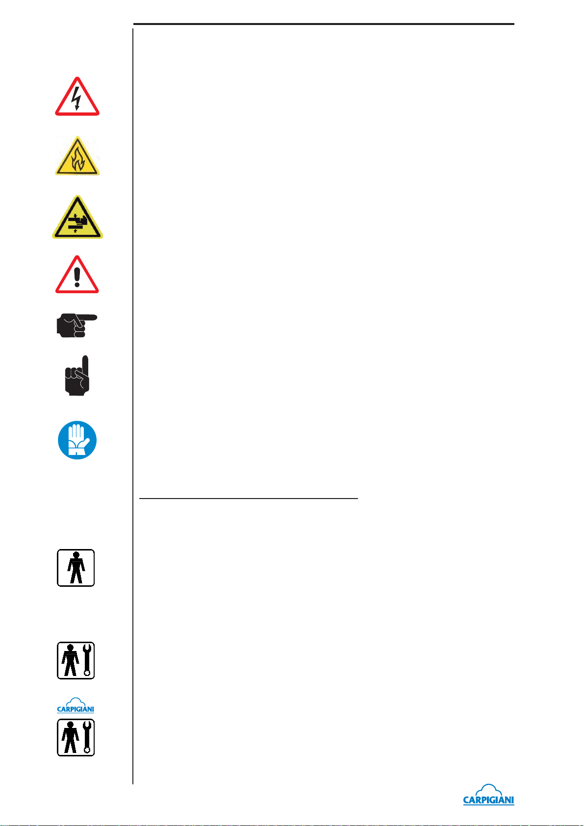
CONVENTIONAL SYMBOLS
CAUTION: ELECTRIC SHOCK DANGER
The staff involved is warned that the non-obsevance of safety rules in carrying out the operation
described may cause an electric shock.
CAUTION DANGER FROM HIGH TEMPERATURES
This warns the staff involved that failure to abide by safety rules in carrying out the operation
described involves the risk of burns and scalds.
CAUTION CRUSHING HAZARD
This warns the staff involved that failure to abide by safety rules in carrying out the operation
described involves the risk of suffering crushed fi ngers or hands.
CAUTION: GENERAL HAZARD
The staff involved is warned that the operation described may cause injury if not performed following safety rules.
NOTE:
It points out signifi cant information for the staff involved.
WARNINGS
The staff involved is warned that the non-observance of warning may cause loss of data and
damage to the machine.
PROTECTIONS
This symbol on the side means that the operator must use personal protection against an implicit
risk of accident.
SYMBOLOGY QUALIFICATION OF THE STAFF
The staff allowed to operate the machine can be differentiated by the level of preparation and responsibility in:
MACHINE OPERATOR
Identify unqualifi ed personnel, those without any specifi c technical abilities who are capable
of carrying out simple jobs, such as: operating the machine using the commands available on
the keypad, the loading and unloading of products used during production, the loading of any
consumable materials, basic maintenance operations, (cleaning, simple blockages, controls of
the instrumentation, etc.).
MAINTENANCE ENGINEER
He/she is a skilled engineer for the operation of the machine under normal conditions; he/she is
able to carry out interventions on mechanical parts and all adjustments, as well as maintenance
and repairs. He/she is qualifi ed for interventions on electrical and refrigeration components.
CARPIGIANI ENGINEER
He/she is a skilled engineer the manufacturer assigned to fi eld interventions for complex jobs
under particular conditions or in accordance with agreements made with the machine's owner.
193 SP USA G_EN - 2011/05 - Ed. 01
- 6 -
SAFETY
When using industrial equipment and plants, one must be aware of the fact that drive mechanisms
(rotary motion), high voltage components, as well as parts subject to high temperatures may cause
serious damage to persons and things.
Who is in charge of plant safety must be on the look-out that:
•an incorrect use or handling shall be avoided;
•safety devices must neither be removed nor tampered with;
•the machine shall be regularly serviced;
•only original spare parts are to be used especially as far as those components with safety
functions are concerned (ex.: protection microswitches, thermostats);
•suitable personal protective equipment is worn;
•high care must be payed during hot product cycling.
To achieve the above, the following is necessary:
•at the working place an instruction manual relevant to the machine should be available;
•tuch documentation must be carefully read and requirements must conse quently be met;
•only adequately skilled personnel should be assigned to electrical equipment;
IMPORTANT!
One must be on the look-out that the staff does not carry out any operation outside its own sphere
of knowledge and responsibility (refer to “Symbology qualifi cation of the staff”)..
NOTE:
According to the standard at present in force, a SKILLED ENGINEER is who, thanks to:
- training, experience and education,
- knowledge of rules, prescriptions and interventions on accident prevention,
- knowledge of machine operating conditions,
is able to realize and avoid any danger and has also been allowed by the person in charge of
plant safety to carry out all kinds of interventions.
193 SP/USA G
WARNING
When installing the machine, insert a differential magnetothermal protection switch on all poles
of the line, adequately sized to the absorption power shown on machine data plate and with
contact opening of 3 mm at least.
•Never put your hand into the machine, alike during production and cleaning operations. Before
carrying out any maintenance operation, make sure that the machine is in “STOP” position
and main switch has been cut out.
•It is forbidden to wash the machine by means of a bolt of water under pressure.
•It is forbidden to remove panels in order to reach the machine inside before having disconnected the machine.
•CARPIGIANI is not responsible for any accident that might happen during operation, cleaning and/or servicing of its units, if this warning has not been fully complied with.
- 7 -
193 SP USA G_EN - 2011/05 - Ed. 01

193 SP/USA G
193 SP USA G_EN - 2011/05 - Ed. 01
- 8 -
1. GENERAL INFORMATION
1.1 GENERAL INFORMATION
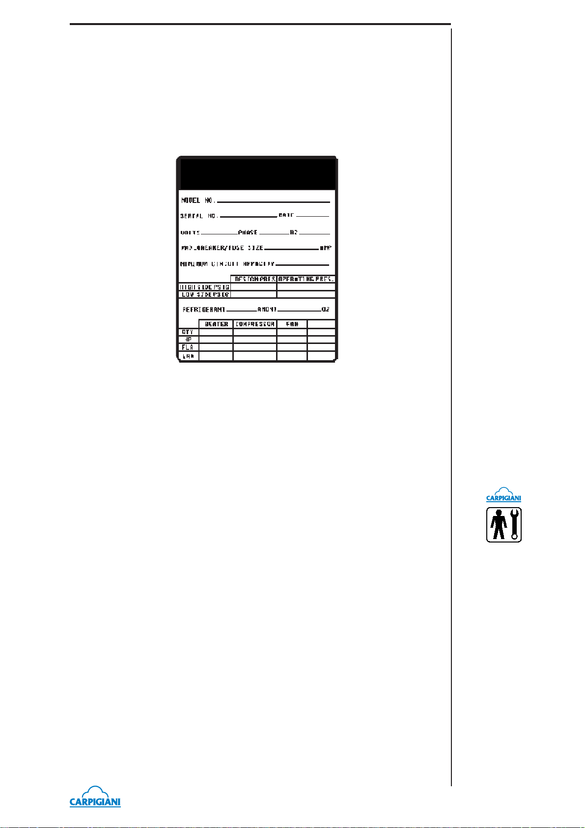
1.1.1 Manufacturer’s identifi cation data
The machine has a data plate carrying manufacturer data, machine type and serial number, assigned when it is manufactured.
Copy of machine data plate to be found on fi rst page of this handbook.
193 SP/USA G
1.1.2 Information about service
All operations of routine maintenance are here described in section “Maintenance”; any additional
operation requiring technical intervention on the machine must be cleared with the manufacturer,
who will also examine the possibility of a factory technician fi eld intervention.
1.1.3 Information to the user
• The manufacturer of the machine is at user ’s disposal for any explanation and information
about the machine operation.
• In case of need, please call the local distributor, or the manufacturer if no distributor is avail-
able.
• Manufacturer ’s service department is available for any information about operation, and
requests of spare parts and service.
1.2 INFORMATION ABOUT THE MACHINE
1.2.1 General data
Counter-top machine to immediately produce and distribute soft express ice cream in two fl avours
+ mixed,
CARPIGIANI recommends to always use high quality mix for ice cream production in order
to satisfy your customers, even the most hard-to-please ones. Any saving made to the prejudice
of quality will surely turn into a loss much bigger than the saving itself.
- 9 -
193 SP USA G_EN - 2011/05 - Ed. 01
193 SP/USA G
Aircooled u
it
Bearing in mind the above statements, please take heed of the following suggestions:
- Make your mixes yourselves from high quality natural ingredients or buy them from reliable
companies.
- Follow closely instructions given by your mix supplier for the preparation of the mixes.
- Do not alter your mix supplier’s recipies, by adding, for instance, water or sugar.
- Taste ice cream before serving it and start selling it only if entirely satisfactory.
- Make sure your staff always keeps the machine clean.
- Have your machine serviced always by companies authorized by CARPIGIANI.
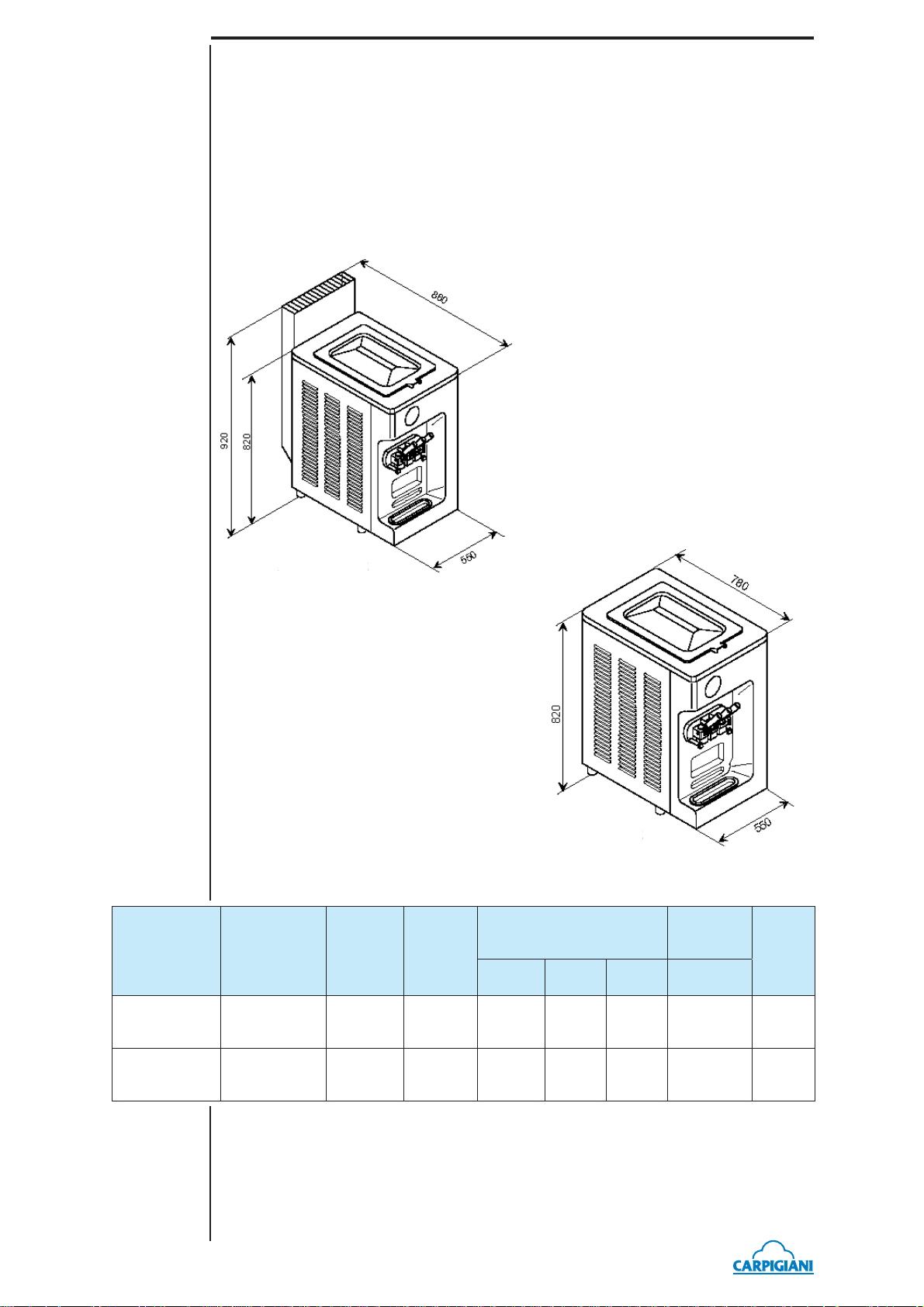
1.2.2 Machine layout
MODEL
193 P/SP N
air
Aircooled unit
n
1.2.3 Technical features
Hopper
Hourly
production *
35 Kg 12 + 12
capacity
liters
Flavors
2 +
mixed
Watercooled unit
tercooled unit
Electrical supply
Volt Phase Cycle kW
400 3 50 4,4 173
Installed
power
Net
weight
kg
193 P/SP N
water
193 SP USA G_EN - 2011/05 - Ed. 01
35 Kg 12 + 12
* The hourly production and the mix quantity for each ice cream can vary, according to the temperature and the type
of mix used and the increase in volume (over-run) desired.
2 +
mixed
400 3 50 4,1 173
- 10 -
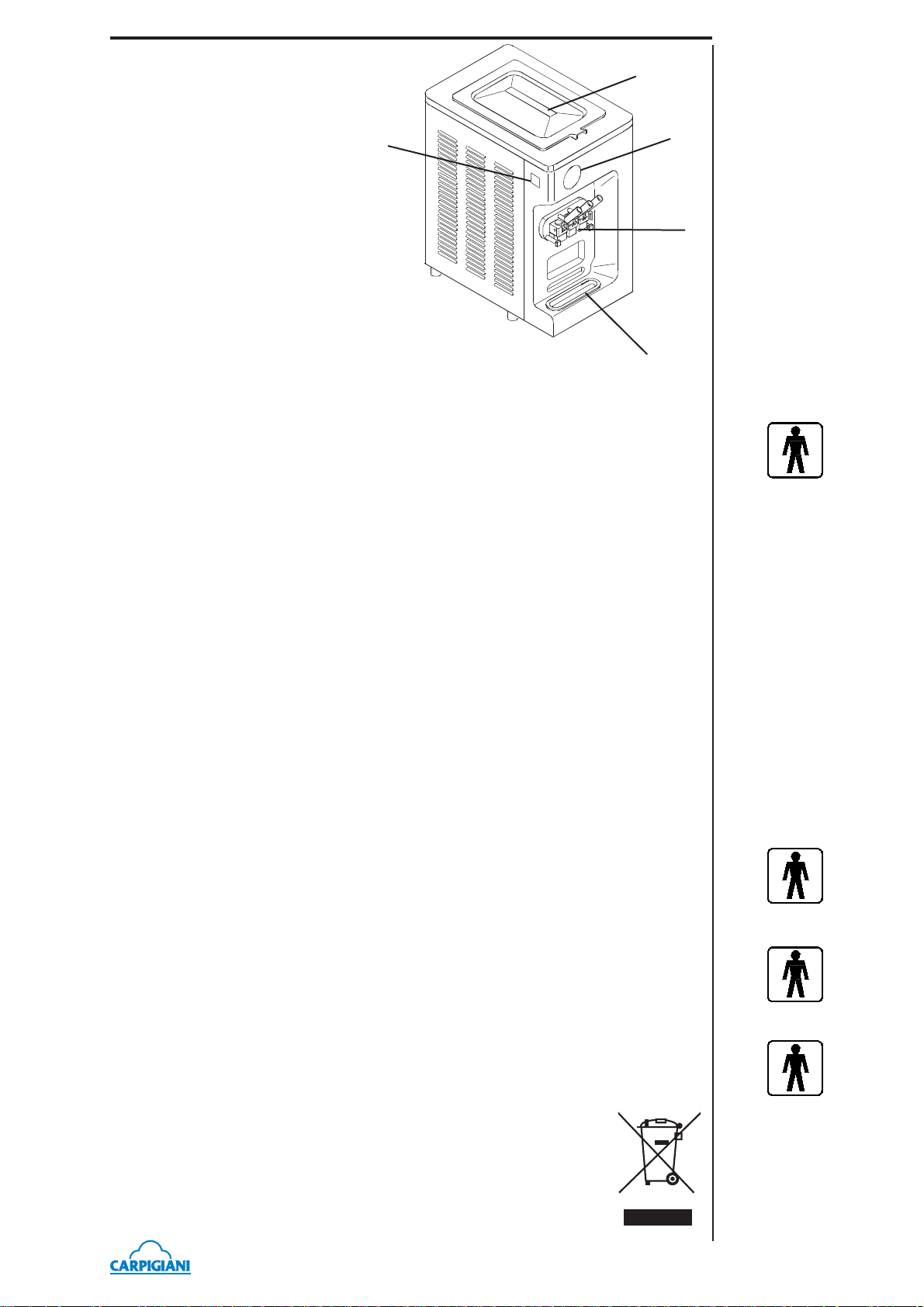
1.2.4 Machine sets location
4
Legend:
1. control panel
2. Freezing cylinder front lid
3. Drip tray shelf
4. Mix tank cover
5. Drip drawer
5
1
2
3
1.3 INTENDED USE
The machines must be used solely for the purpose described in chapter 1.2.1, “General information” within the functional limits decribed below.
Voltage ±10%
Min air temperature 10°C
Max air temperature 43°C
Min water temperature 10°C
Max water temperature 30°C
Min. water pressure 0,1 MPa (1 bar)
Max water pressure 0,8 MPa (8 bar)
Max relative humidity 85%
193 SP/USA G
The machine has been designed for its use in places which are not subject to explosion-proof
standards; its use is thus bound to conforming places and normal atmospher
1.4 NOISE
The steady acoustic pressure level weighed A in a working place alike by watercooled and by
aircooled machines is less than 70 dB(A).
1.5 STORING A MACHINE
The machine must be stored in a dry and dump-free place.
Before storing the machine, wrap it in a cloth in order to protect it against dust and else.
1.6 DISPOSAL OF PACKING STUFFS
When opening the packing crate, divide packing stuffs per type and get rid of them according to
laws in force in machine installation country.
1.7 WEEE (Waste Electrical and Electronic Equipment)
In conformity with the European Directives 2006/66/EC, on batteries and accumulators and waste
batteries and accumulators, and 2002/96/EC, also known as WEEE, the presence of the symbol
on the side of the product or packaging means that the product must not be disposed of with normal urban waste. Instead, it is the user’s responsibility to dispose of this product
by returning it to a collection point designated for the recycling of electrical and
electronic equipment waste. Separate collection of this waste helps to optimize the
recovery and recycling of any reclaimable materials and also reduces the impact
on human health and the environment.
For more information concerning the correct disposal of this product, please contact
your local authority or the retailer where this product was purchased.
- 11 -
193 SP USA G_EN - 2011/05 - Ed. 01

193 SP/USA G
193 SP USA G_EN - 2011/05 - Ed. 01
- 12 -
 Loading...