

Page 1

INSTRUCTION HANDBOOK
193 P/SP N
Page 2

193 P/SP N
We wish to thank you for the preference granted to us by purchasing one of
CARPIGIANI machines.
To the best guarantee, since 1993 CARPIGIANI has submitted its own Quality
System to the certifi cation according to the international Standard ISO 9001,
nowadays its production has got UNI-EN-ISO 9001:2008 Certifi ed Quality System.
Moreover, CARPIGIANI machines comply with following European Directives:
- “Machinery” Directive 2006/42/EC,
- “Low Voltage” Directive 2006/95/EC,
- “EMC” Directive 2004/108/EC,
- “PED” Directive 97/23/EC,
- Regulation 2004/1935/EC relating to “Materials and articles in contact with foodstuffs”
CARPIGIANI
Via Emilia, 45 - 40011 Anzola dell'Emilia (Bologna) - Italy
Tel. +39 051 6505111 - Fax +39 051 732178
This manual contains a TRANSLATION OF THE ORIGINAL INSTRUCTIONS and may not
be reproduced, transmitted, transcribed, fi led in a data retrieval system or translated into other
languages, without the prior written permission of CARPIGIANI.
The purchaser has the wright to reprint it for his own offi ce use.
CARPIGIANI policy pursues a steady reasearch and development, thus it reserves the right to
make changes and revisions whenever deemed necessary and without being bound to previous
statements to the purchaser.
Edition: 04 Date: 2013/10
Editor: AM Verifi ed: PB Approved: RV
193 P/SP N_EN - 2013/10 - Ed. 04
Modifi cations: 3.2 - 3.5 - 3.7 - 3.9 - 4
- 2 -
Page 3

GENERAL INDEX
SECT. FOREWORD
INSTRUCTION HANDBOOK .....................................................................................5
PURPOSE ......................................................................................................................5
HANDBOOK STRUCTURE ........................................................................................5
ADDITIONAL DOCUMENTATION ...........................................................................5
CONVENTIONAL SYMBOLS ....................................................................................6
SAFETY ........................................................................................................................7
QUALIFICATION OF THE STAFF .............................................................................7
WARNING ....................................................................................................................7
SECT. 1 - GENERAL INFORMATION
1.1 GENERAL INFORMATION .....................................................................................9
1.1.1 MANUFACTURER’S IDENTIFICATION DATA ............................................9
1.1.2 INFORMATION ABOUT SERVICE ................................................................9
1.1.3 INFORMATION TO THE USER ......................................................................9
1.2 INFORMATION ABOUT THE MACHINE .............................................................9
1.2.1 GENERAL DATA ..............................................................................................9
1.2.2 MACHINE LAYOUT ........................................................................................10
1.2.3 TECHNICAL FEATURES ................................................................................10
1.2.4 MACHINE SETS LOCATION .........................................................................11
1.3 INTENDED USE .........................................................................................................11
1.4 NOISE ...........................................................................................................................11
1.5 STORING A MACHINE .............................................................................................11
1.6 DISPOSAL OF PACKING STUFFS..........................................................................11
1.7 WEEE (Waste Electrical and Electronic Equipment) .............................................11
193 P/SP N
SECT. 2 - INSTALLATION
2.1 ROOM NECESSARY TO THE MACHINE USE ....................................................13
2.2 MACHINE WITH AIRCOOLED CONDENSER ....................................................13
2.2.1 AIRFLOW ..........................................................................................................13
2.3 MACHINES WITH WA TERCOOLED CONDENSER ..........................................14
2.3.1 WATER VALVE ADJUSTMENT ......................................................................14
2.4 ELECTRIC CONNECTION ......................................................................................14
2.4.1 REPLACEMENT OF POWER SUPPLY CORD ..............................................14
2.5 REFILLING .................................................................................................................14
2.6 MACHINE TESTING .................................................................................................14
SECT. 3 - DIRECTION FOR USE
3.1 MACHINE CONFIGURATION ................................................................................15
3.2 ELECTRONIC CONTROL KEYBOARD AND BUTTON FUNCTIONS ...........16
3.3 SPIGOT HANDLE ......................................................................................................19
3.4 “R” PUMP ....................................................................................................................19
3.5 PRELIMINARY OPERATIONS, WASHING AND SANITIZING........................20
3.5.1 CLEANING .......................................................................................................20
3.5.2 SANITIZING .....................................................................................................22
3.5.3 HYGIENE ..........................................................................................................23
3.6 STARTING THE MACHINE .....................................................................................23
3.7 PRODUCTION ............................................................................................................24
3.8 PASTEURIZATION ....................................................................................................24
3.9 ALARMS ......................................................................................................................25
3.9.1 BLACKOUT ......................................................................................................27
3.10 PROGRAMMING FOR THE USER .......................................................................27
- 3 -
193 P/SP N_EN - 2013/10 - Ed. 04
Page 4

193 P/SP N
SECT. 4 - SAFETY DEVICES
4.1 SAFETY SYSTEMS ON THE MACHINE ...............................................................29
SECT.5 - CLEANOUT DISASSEMBLING AND REASSEMBLING OF
PARTS IN CONTACT WITH THE PRODUCT
5.1 GENERAL DESCRIPTION .......................................................................................31
5.2 WASHING CONDITIONS .........................................................................................31
5.3 SUGGESTIONS...........................................................................................................31
5.4 HOW TO USE XSAN DETERGENT/SANITIZER ................................................32
5.5 PROGRAMMED CLEANING TIME .......................................................................32
5.6 DRAINING AND CLEANING...................................................................................32
5.7 DISASSEMBLING MIX PUMP ...............................................................................33
5.8 DISASSEMBLING THE TANK MIXER..................................................................33
5.9 DISASSEMBLING FRONT LID ...............................................................................34
5.10 DISASSEMBLING OF THE BEATER .....................................................................34
5.11 WASHING AND SANITIZING COMPONENTS ....................................................35
5.12 REASSEMBLING THE TANK MIXER ...................................................................35
5.13 REASSEMBLING THE MIX PUMP .......................................................................36
5.14 REASSEMBLING THE BEATER ............................................................................37
5.15 REASSEMBLING FRONT LID ................................................................................37
5.16 SANITIZING THE WHOLE MACHINE ................................................................38
5.17 PRIMING THE MIX PUMP ......................................................................................38
SECT. 6 - MAINTENANCE
6.1 SERVICING TYPOLOGY .........................................................................................39
6.2 WATERCOOLING .....................................................................................................40
6.3 AIRCOOLING.............................................................................................................40
6.4 TABLE OF SPARE PARTS EQUIPMENT ..............................................................41
SECT. 7 - TROUBLESHOOT GUIDE
7.1 TROUBLESHOOT GUIDE .......................................................................................43
193 P/SP N_EN - 2013/10 - Ed. 04
- 4 -
Page 5
FOREWORD
INSTRUCTION HANDBOOK
Editing this handbook, it was taken into due account European Community directions on safety
standards as well as on free circulation of industrial products within E.C.
PURPOSE
This handbook was conceived taking machine users' needs into due account.
T opics relevant to a correct use of the machine have been analyzed in order to keep unchanged in
the long run quality features charachterizing CARPIGIANI machines all over the world.
A signifi cant part of this handbook refers to the conditions necessary to the machine use and to
the necessary procedure during cleanout as well as routine and special maintenance.
Nevertheless, this handbook cannot meet all demands in details. In case of doubts or missing
information, please apply to:
CARPIGIANI Via Emilia, 45 - 4001 1 Anzola dell'Emilia (Bologna) - Italy
Tel. +39 051 6505111 - Fax +39 051 732178
HANDBOOK STRUCTURE
This handbook is divided in sections, chapters and subchapters in order to be consulted more easily.
193 P/SP N
Section
A section is the part of the handbook identifying a specifi c topic related to a machine part.
Chapter
A chapter is that part of a section describing an assembly or concept relevant to a machine part.
Subchapter
It is that part of a chapter detailing the specifi c component of a machine part.
It is necessary that each person involved in the machine operation reads and clearly understands
those parts of the handbook of his/her own concern, and particularly:
• The Operator must read the chapters concerning the machine star-up and the operation of
machine components.
• A skilled technician involved in the installation, maintenance, repair , etc., of the machine must
read all parts of this handbook.
ADDITIONAL DOCUMENTATION
Along with an instruction manual, each machine is supplied also with additional documentation:
• Part list: a list of spare parts which is delivered together with the machine for its maintenance.
• Wiring diagram: a diagram of wiring connections is placed in the machine.
Before using the machine read carefully the instruction handbook.
Pay attention to the safety instructions.
- 5 -
193 P/SP N_EN - 2013/10 - Ed. 04
Page 6
193 P/SP N
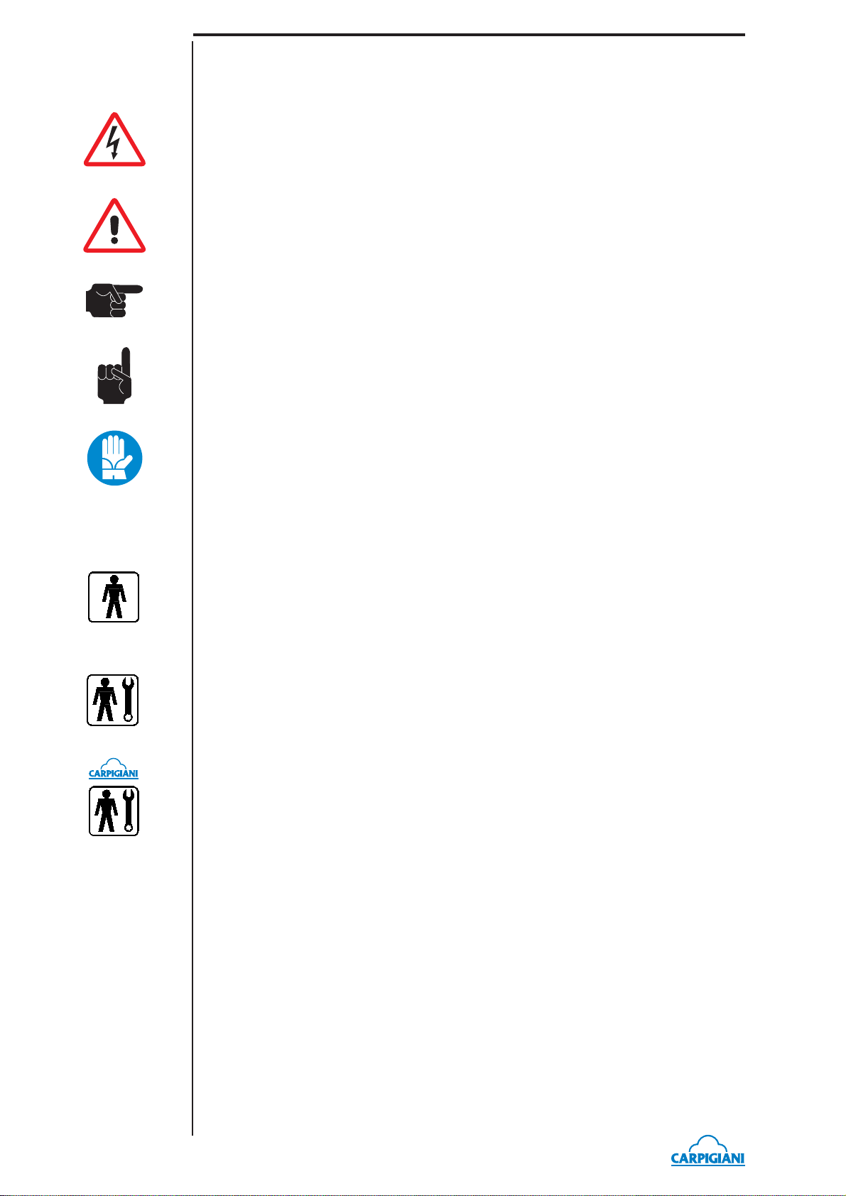
CONVENTIONAL SYMBOLS
CAUTION: ELECTRIC SHOCK DANGER
The staff involved is warned that the non-obsevance of safety rules in carrying out the operation
described may cause an electric shock.
CAUTION: GENERAL HAZARD
The staff involved is warned that the operation described may cause injury if not performed following safety rules.
NOTE
It points out signifi cant information for the staff involved.
WARNINGS
The staff involved is warned that the non-observance of warning may cause loss of data and
damage to the machine.
PROTECTIONS
This symbol on the side means that the operator must use personal protection against an implicit
risk of accident.
QUALIFICATION OF THE STAFF
MACHINE OPERATOR
He/she is an unskilled person , who has no specifi c expertise and can only carry out easy chores,
such as the machine operation by means of controls available on the push-button panel, and fi lling
and drawing of products used during operations.
MAINTENANCE ENGINEER
He/she is a skilled engineer for the operation of the machine under normal conditions; he/she is
able to carry out interventions on mechanical parts and all adjustments, as well as maintenance
and repairs. He/she is qualifi ed for interventions on electrical and refrigeration components.
CARPIGIANI ENGINEER
He/she is a skilled engineer the manufacturer assigned to fi eld interventions for complex jobs
under particular conditions or in accordance with agreements made with the machine's owner.
193 P/SP N_EN - 2013/10 - Ed. 04
- 6 -
Page 7
SAFETY
When using industrial equipment and plants, one must be aware of the fact that drive mechanisms
(rotary motion), high voltage components, as well as parts subject to high temperatures may cause
serious damage to persons and things.
Who is in charge of plant safety must be on the look-out that:
• any incorrect use or handling shall be avoided;
• safety devices must neither be removed nor tampered with;
• the machine shall be regularly serviced;
• only original spare parts are to be used especially as far as those components with safety
functions are concerned (ex.: protection microswitches, thermostats);
• suitable personal protective equipment is worn;
To achieve the above, the following is necessary:
• at the working place an instruction manual relevant to the machine should be available;
• such documentation must be carefully read and requirements must conse quently be met;
• only adequately skilled personnel should be assigned to electrical equipment;
• be on the look out that no technician will ever carry out interventions outside his own knowl-
edge and responsibility sphere.
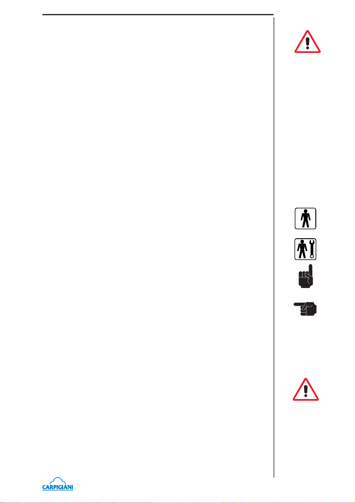
QUALIFICATION OF THE STAFF
193 P/SP N
Staff attached to the machine can be distinguished according to training and responsibility as follows:
OPERATOR
- A person who has not necessarily a high technical knowledge, just trained for ordinary operation
of the machine, such as: startup, stop, fi lling, basic maintenance (cleanout, simple blocking,
instrumentation checkings, etc.).
SKILLED ENGINEER
- A person enganged on more complicated operations of installation, maintenance, repairs, etc.
IMPORTANT!
One must be on the look-out that the staff does not carry out any operation outside its own sphere
of konwledge and responsibility.
NOTE:
According to the standard at present in force, a SKILLED ENGINEER is who, thanks to:
- training, experience and education,
- knowledge of rules, prescriptions and interventions on accident prevention,
- knowledge of machine operating conditions,
is able to realize and avoid any danger and has also been allowed by the person in charge of plant
safety to carry out all kinds of interventions.
WARNING
When installing the machine, insert a differential magnetothermal protection switch on all poles of
the line, adequately sized to the absorption power shown on machine data plate and with contact
opening of 3 mm at least.
• Never put your hand into the machine, alike during production and cleaning operations. Before
carrying out any maintenance operation, make sure that the machine is in “STOP” position
and main switch has been cut out.
• It is forbidden to wash the machine by means of a bolt of water under pressure.
• It is forbidden to remove panels in order to reach the machine inside before having discon-
nected the machine.
• CARPIGIANI is not responsible for any accident that might happen during operation, clean-
ing and/or servicing of its units, if this warning has not been fully complied with.
- 7 -
193 P/SP N_EN - 2013/10 - Ed. 04
Page 8

193 P/SP N
193 P/SP N_EN - 2013/10 - Ed. 04
- 8 -
Page 9
1. GENERAL INFORMATION
1.1 GENERAL INFORMATION
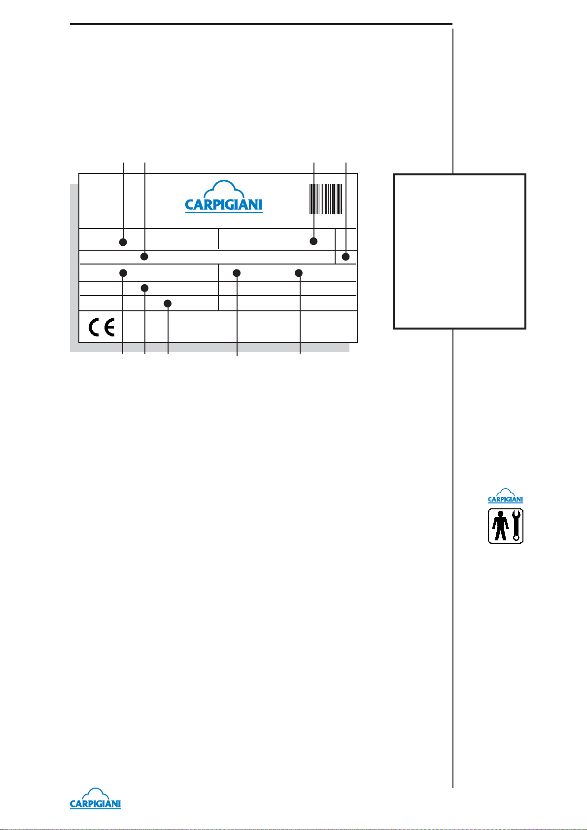
1.1.1 Manufacturer’s identifi cation data
The machine has a data plate carrying manufacturer data, machine type and serial number, assigned when it is manufactured.
Copy of machine data plate to be found on fi rst page of this handbook.
AB F G
LEGEND:
193 P/SP N
100089654588-4
Matr.
ANZOLA EMILIA - BOLOGNA - ITALY
Cod.
V Hz kW
A
Gas kg
CDE H
I
A= Serial number
B= Machine type
C= V oltage
D= Main-switch
amperometric value
E= Gas type and weight
F= Machine code
G= Condensation
H= Frequency
I= Power input
1.1.2 Information about service
All operations of routine maintenance are here described in section “Maintenance”; any additional
operation requiring technical intervention on the machine must be cleared with the manufacturer,
who will also examine the possibility of a factory technician fi eld intervention.
1.1.3 Information to the user
• The manufacturer of the machine is at user ’s disposal for any explanation and information
about the machine operation.
• In case of need, please call the local distributor, or the manufacturer if no distributor is avail-
able.
• Manufacturer ’s service department is available for any information about operation, and
requests of spare parts and service.
1.2 INFORMATION ABOUT THE MACHINE
1.2.1 General data
Counter-top machine to immediately produce and distribute soft express ice cream in two fl avours
+ mixed, available with pump to ensure a higher overrun.
CARPIGIANI recommends to always use high quality mix for ice cream production in order
to satisfy your customers, even the most hard-to-please ones. Any saving made to the prejudice
of quality will surely turn into a loss much bigger than the saving itself.
- 9 -
193 P/SP N_EN - 2013/10 - Ed. 04
Page 10
193 P/SP N
Aircooled u
it
Bearing in mind the above statements, please take heed of the following suggestions:
- Make your mixes yourselves from high quality natural ingredients or buy them from reliable
companies.
- Follow closely instructions given by your mix supplier for the preparation of the mixes.
- Do not alter your mix supplier’s recipies, by adding, for instance, water or sugar.
- Taste ice cream before serving it and start selling it only if entirely satisfactory.
- Make sure your staff always keeps the machine clean.
- Have your machine serviced always by companies authorized by CARPIGIANI.
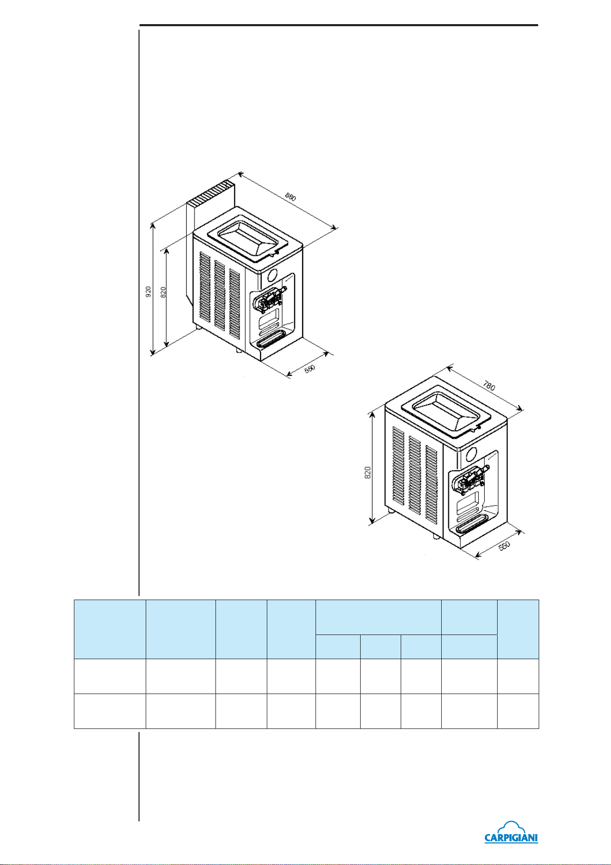
1.2.2 Machine layout
MODEL
193 P/SP N
air
Aircooled unit
n
1.2.3 Technical features
Hopper
Hourly
production *
35 Kg 12 + 12
capacity
liters
Flavors
2 +
mixed
Watercooled unit
tercooled unit
Electrical supply
Volt Phase Cycle kW
400 3 50 4,4 173
Installed
power
Net
weight
kg
193 P/SP N
water
193 P/SP N_EN - 2013/10 - Ed. 04
35 Kg 12 + 12
* The hourly production and the mix quantity for each ice cream can vary, according to the temperature and the type
of mix used and the increase in volume (over-run) desired.
2 +
mixed
400 3 50 4,1 173
- 10 -
Page 11
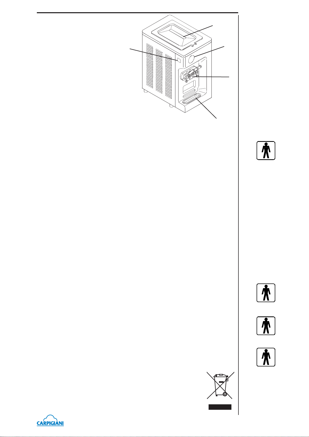
1.2.4 Machine sets location
4
Legend:
1. control panel
2. Freezing cylinder front lid
3. Drip tray shelf
4. Mix tank cover
5. Drip drawer
5
1
2
3
1.3 INTENDED USE
The machines must be used solely for the purpose described in chapter 1.2.1, “General information” within the functional limits decribed below.
Voltage ±10%
Min air temperature 10°C
Max air temperature 43°C
Min water temperature 10°C
Max water temperature 30°C
Min. water pressure 0,1 MPa (1 bar)
Max water pressure 0,8 MPa (8 bar)
Max relative humidity 85%
193 P/SP N
The machine has been designed for its use in places which are not subject to explosion-proof
standards; its use is thus bound to conforming places and normal atmospher
1.4 NOISE
The steady acoustic pressure level weighed A in a working place alike by watercooled and by
aircooled machines is less than 70 dB(A).
1.5 STORING A MACHINE
The machine must be stored in a dry and dump-free place.
Before storing the machine, wrap it in a cloth in order to protect it against dust and else.
1.6 DISPOSAL OF PACKING STUFFS
When opening the packing crate, divide packing stuffs per type and get rid of them according to
laws in force in machine installation country.
1.7 WEEE (Waste Electrical and Electronic Equipment)
In conformity with the European Directives 2006/66/EC, on batteries and accumulators and waste
batteries and accumulators, and 2002/96/EC, also known as WEEE, the presence of the symbol
on the side of the product or packaging means that the product must not be disposed of with normal urban waste. Instead, it is the user’s responsibility to dispose of this product
by returning it to a collection point designated for the recycling of electrical and
electronic equipment waste. Separate collection of this waste helps to optimize the
recovery and recycling of any reclaimable materials and also reduces the impact
on human health and the environment.
For more information concerning the correct disposal of this product, please contact
your local authority or the retailer where this product was purchased.
- 11 -
193 P/SP N_EN - 2013/10 - Ed. 04
Page 12

193 P/SP N
193 P/SP N_EN - 2013/10 - Ed. 04
- 12 -
Page 13
2. INSTALLATION
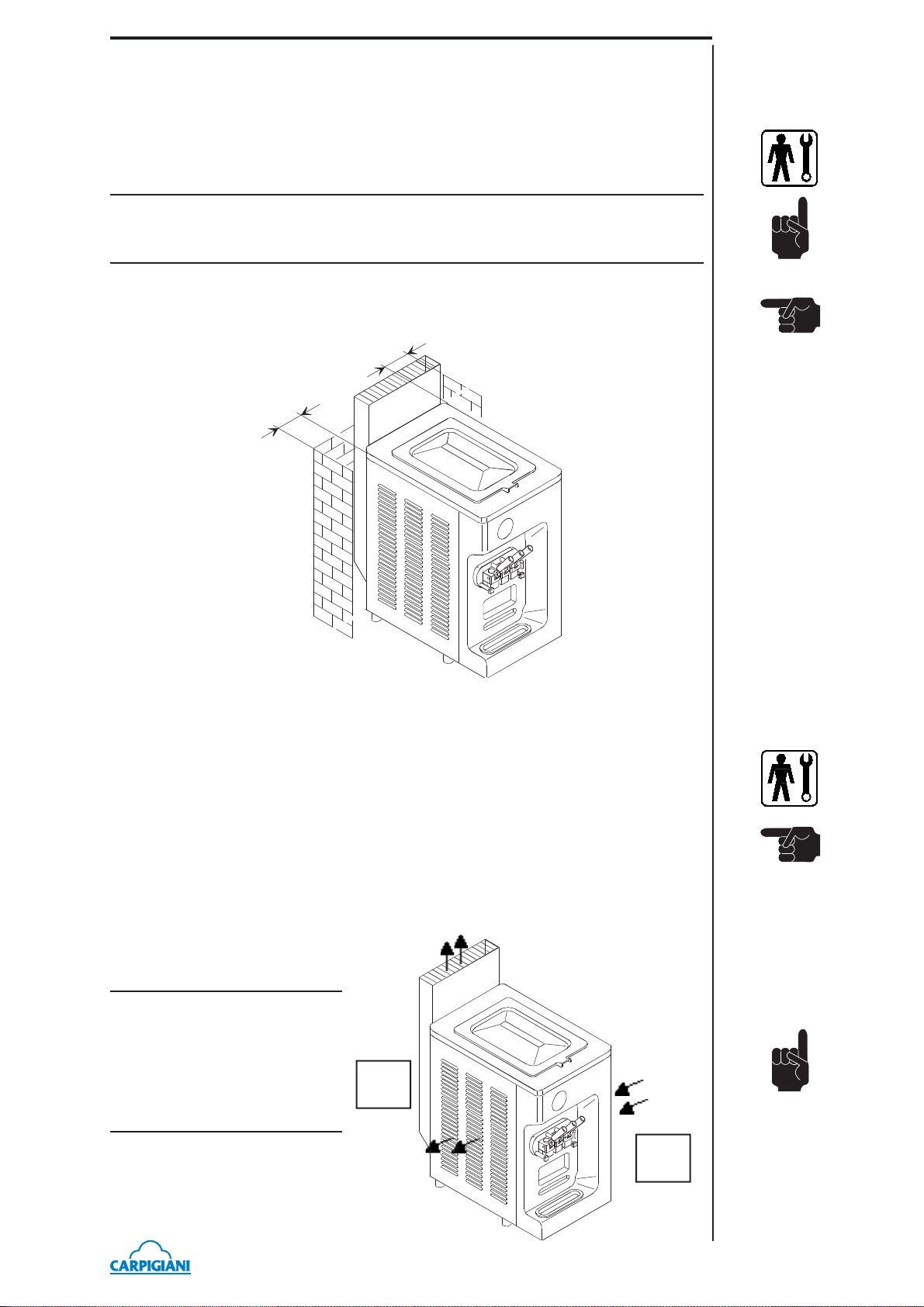
2.1 ROOM NECESSARY TO THE MACHINE USE
The machine must be installed in such a way that air can freely circulate allaround.
Rooms for the approach to the machine must be left free in order to enable the operator to act
without constraint and also to immediately leave working area, if need be.
ATTENTION
MACHINES WITH AIRCOOLED CONDENSER must be installed no closer than 8 cm
to any wall in order to allow free air circulation around the condenser.
NOTE
An insuffi cient air circulation affects operation and output capacity of the machine.
m
c
8
m
c
8
193 P/SP N
2.2 MACHINE WITH AIRCOOLED CONDENSER
Machines with aircooled condenser must be installed no closer than 8 cm to any wall in order to
allow free air circulation around the condenser.
NOTE
An insuffi cient air circulation affects operation and output capacity of the machine.
2.2.1 Airfl ow
The CARPIGIANI 193 P/SP N machine is provided with an internal fan motor which takes fresh
air from the right panel of the machine
and exhausts the heated air through the
left panels and through the stack on the
rear of the machine
IMPORTANT
Do not place topping containers,
syrup containers or other prod-
ucts, in front of the left panel of the
machine because the hot air fl ow
increases the temperature of the
products or may melt them.
topping
AIR OUT
NO
AIR OUT
AIR IN
OK
topping
- 13 -
193 P/SP N_EN - 2013/10 - Ed. 04
Page 14

193 P/SP N
2.3 MACHINES WITH WATERCOOLED CONDENSER
To make the machine run, a watercooled machine must be connected to running water supply,
or to a cooling tower. Water must have a pressure of 1 Bar at least and a delivery at least equal
to the estimated hourly consumption. Connect inlet pipe marked by plate “Water Inlet” to water
supply installing a shut-off valve, and outlet pipe marked by plate “W ater Outlet” to a drain pipe,
installing a shut-off valve.
2.3.1 Water valve adjustment
WARNING
If water valve must be reset, this operation will have to be carried out by skilled personnel, only.
Valve adjustment must be carried out in such a way that no water fl ows when machine is of f and
lukewarm water fl ows when machine is on.
NOTE:
Water consumption increases if temperature of entering water is above 20°C.
ATTENTION:
Do not leave the machine in a room with temperature below 0°C
without fi rst draining water from the condenser.
2.4 ELECTRIC CONNECTION
Before connecting the machine to the mains, check that machine voltage indicated in data plate
corresponds with the mains (see sec. 1.1.1 point C).
Insert a differential magnetothermal protection switch adequately sized to absorption capacity
required (see sec. 1.1.1 point D) and with contact opening of 3 mm at least.
WARNING
Yellow/green ground wire must be connected to a good ground outlet.
Rotation direction by three-phased machines
The beater rotates anticlockwise.
Reversing rotation direction
T o reverse the direction rotation, when wrong, it is necessay to interchange two of the three leads
coming from the circuit breaker.
2.4.1 Replacement of power supply cord
If the machine main cable is damaged, it must be replaced through a cable with similar features.
Replacement will have to be carried out by skilled technicians only.
2.5 REFILLING
Motor installed in the machine is of the type with lubrication for life; no action of checking/
replacing or topping up is necessary. Gas fi lling necessary to the freezing system is carried out
at CARPIGIANI works during machine postproduction testing. If a gas addition happens to be
made, this must be carried out by skilled technicans, only, who can also fi nd out trouble origin.
2.6 MACHINE TESTING
A postproduction test of the machine is carried out at Carpigiani premises; Operation and output
functionality of the machine are thoroughly tested. Machine test at end user’s must be carried
out by skilled technicians or by one of CARPIGIANI engineers. After the machine positioning
and correct connections, also carry out all operations necessary to functional check and test of
the machine.
193 P/SP N_EN - 2013/10 - Ed. 04
- 14 -
Page 15

3. DIRECTION FOR USE
3.1 MACHINE CONFIGURATION
The machine has a motor to drive the beater, and a cooling system with water or air condenser.
Soft ice cream is prepared by fi lling the tanks with cold mix (+4°C) and starting the au-
tomatic production cycle, until the ideal ice cream consistency set by CARPIGIANI is
reached. Thanks to the pump, the mix enters the freezing cylinder already mixed with air; ice
cream is produced only when it needs to be served. The spigot head allows a single portion of
soft ice cream to be distributed. At the same time, the same amount of mix moves from the tanks
into the freezing cylinders.
193 P/SP N
- 15 -
193 P/SP N_EN - 2013/10 - Ed. 04
Page 16

193 P/SP N
3.2 ELECTRONIC CONTROL KEYBOARD AND BUTTON
FUNCTIONS
Details of the panel are shown in the picture below.
Display
On turning the machine on and during its operation, a series of messages are displayed on the
screen.
Led indicators
The led indicator lights up when the function corresponding to the symbol next to it is activated.
STOP key
In this function, your machine is off and relevant led (backlighted) is on. From
Stop position you can enter in any machine function. For the change, IT IS always
NECESSARY to fi rst return to STOP. On the display:
10:33:21 Fri
If you leave the machine in Stop when mix is above the level, the message “Why
in STOP ??” will be displayed after 30” so as to alert the user to set the machine at
Production, Pasteurization or Storage modes.
PRODUCTION key
The function of Production can only be entered if the mix has not reached the low
lovel. The product is cooled in the cylinder till its programmed consistency value
is reached (HOT).
193 P/SP N_EN - 2013/10 - Ed. 04
As soon as you enter in Production, you also enter in a menu through which you
can set the type of product you may wish to serve from each of the two sides, i.e.,
SoftIce (custard), WaterIce (fruit) or Yogurt; you now have following display:
Custard Custard
This window shows the type of product served from each of the two sides:
SoftIce (left) = side 1 produces Softice
SoftIce (right) = side 2 produces Softice
What has been illustrated is the fi rst page of the menu; by pressing and holding the
Production key you access the following combinations, specifi cally:
SoftIce WaterIce (Custard in side 1 and Fruit on side 2)
- 16 -
Page 17

SoftIce Yogurt (Custard in side 1 and Yoghurt in side 2)
WaterIce SoftIce (Fruit in side 1 and Custard in side 2)
WaterIce WaterIce (Fruit in side 1 and Fruit in side 2)
WaterIce Yogurt (Fruit in side 1 and Yoghurt in side 2)
Yogurt SoftIce (Yoghurt in side 1 and Custard in side 2)
Yogurt WaterIce (Yoghurt in side 1 and Custard in side 2)
Yogurt Yogurt (Yoghurt in side 1 and Yoghurt in side 2)
If one side is disabled the only option allowed and displayed in the menu is the
choice of the type of product in the active side.
Once the desired combination has been displayed, you shall wait for 3 seconds (no
key needs be pressed) and the machine will automatically enter in the selected type
of production, so loading relevant settings.
You will automatically enter in Production mode, now, and the display will be as
follows:
Ice cream Ready!
TEV +4°C L-14
The fi rst line indicates whether ice cream is ready to be dispensed (Icecream Ready!)
or not yet (Do not Serve!).
If the message is Do not Serve!, it means that ice cream has not yet reached its
programmed consistency and you shall consequently wait .
The second line indicates the temperature in the hopper the number of days to next
machine wash. The example above shows there are 14 days to next wash.By pressing
Production you pass to the various “windows” or screens hereafter described:
193 P/SP N
Hopper Ð +014°C
Ð +015°C Ð +013°C
The fi rst line (top) of this window shows the Hopper temperature:
Ð = on, when cooling the hopper +014°C=temperature in the hopper (TEV)
The second line shows the temperature of the two Cylinders:
Ð left = on, when cooling the cylinder 1 +015°C=temperature in cylinder 1 (TEC1)
Ð right = on, when cooling cylinder 2 +013°C=temperature in cylinder 2 (TEC2)
Hot=085 Hot=085
Set=100 Set=100
The fi rst line (top) of this window shows the following:
HOT=085: reading of current consistency in the cylinders of both sides
The second line shows the following:
Set=100 : Set HOT of both side (left side 1, right side 2)
Today’s Cones
12345
This window shows the Cones of the day (starting 0:00 to 23.59):
12345 = number of conses dispensed in the day
Total Cones
0923456780
This window shows the no. of total Cones:
0923456780 = number of total cones dispensed.
TC1 +013 TC2 +013
TE1 -012 TE2 -012
This window shows the sensors (neither °C nor °F are displayed):
TEC = Cylinder Thermostat (1 = side 1, 2 = side 2)
TE = Evaporator Thermostat (1 = side 1, 2 = side 2)
- 17 -
193 P/SP N_EN - 2013/10 - Ed. 04
Page 18

193 P/SP N
TEV+014 TGV-022
This window shows sensors TEV and TGV (neither °C nor °F are displayed):
TEV = TGV hopper thermostat = thermostat hopper defrost
By pressing Production again, you return to the starting screen.
CLEANING key
By pressing this key, the beaters and the pumps will run 30 seconds. This is a timed
function which automatically ends when the programmed time (30 seconds) ends.
This machine has an automatic system commanding the wash of parts in contact
with food products every 14 days. This system, called “WASH”, inhibits the
production at the end of the 14th day.
Function KEYBOARD LOCK
In order to clean the keyboard with a clean cloth, it is recommended to lock the
keys on the board as follows:
Press the key
keyboard is now locked. You can clean it, now , with no risks. T o unlock, press again
3 seconds and the check lamp will switch off.
PASTEURIZATION key
This program will never start if the mix in one of the hoppers has reached the low
level. If the lowest level in the right-hand hopper is not covered, the display shows
“MIX OUT 2”, if the lowest level in the left-hand hopper is not covered, the display shows “MIX OUT 1”, if both are not covered, the display shows just “MIX
OUT 1”; the led lights and an acoustic signal will play continuously. The
pasteurization process takes place every day at 2:00 (if programmed).
AUTOMA TIC P ASTEURIZA TION CYCLE: while the machine is in production
mode and the mix is over the mean level, the automatic heat treatment cycle will
automatically start at a certain time (as a rue, at 2,00).
During the Pasteurization cycle, the mix in the hopper and in the cylinder is heated
till 65°C are reached, it is then held at this temperature for 30 minutes and, last,
cooled down to 4°C.
At the end of the cyle, the display shows the message “Pasto End” as well as the
date and time of operation end. The machine will then automatically pass to the
STORAGE function.
For icecream to be served, press STOP and soon after PROD.
Manual start of the Pasteurization process (if the step “Pasto Start Time” has not
been set) requires you to press the Pasteurization key and hold it 5 seconds down.
3 seconds, the check lamp will blink to indicate that the
193 P/SP N_EN - 2013/10 - Ed. 04
NOTE:
Once it has started, the pasteurization cycle cannot be stopped. The complete
cycle takes about 2 hours. During the heat treatment and Pause, the mix inside the
machine is very hot, so neither try to take it out, nor to disassemble the machine.
WARNING
Neither serve ice cream, nor disassemble the machine during the heat
treatment because the profduct is very hot and under pressure.
STORAGE key
By pressing the Storage key, the product is conveyed into the hopper and into the
cylinder at a temperature of 4°C.
- 18 -
Page 19

LEVEL
If the mix in left hopper falls below the minimum level, "Mix Out 1" displays
steadily on the fi rst line, if the mix in right hopper falls below the minimum level,
"Mix Out 2" displays steadily on the fi rst line, fi nally if both levels fall below the
minimum level, only "Mix Out" displays steadily on the fi rst line .
193 P/SP N
In all these cases the low level hopper led on the keyboard lights up
buzzer beeps continuously.
The second line displays the number of cones that can be drawn (Last Cones) before
the machine automatically sets to Storage.
NOTE:
When the “Mix Out!” message is on, it is not possible to enter the following
Production or Pasteurization pages.
3.3 SPIGOT HANDLE
In order to dispense the product, place a cup or a cone under
the spout and slowly pull down the disepnsing handle. As
soon as the product comes out, twist the cup or the cone to
form a cone-shaped serving. When the portion has reached
the desired size, close the dispensing handle and quickly
pull the cone or the cup down in order to sharpen the tip.
and the
Dispensing
handle
3.4 “R” PUMP
“R” pump allows, by changing position of regulator pos. 271, to vary proportions between air
and mix conveyed to the freezing cylinder; so, within certain limits, it allows overrun regulation
depending on mix used.
“R” pump regulator should be set to the middle position.
If, after dispensing a signifi cant number of cones, ice cream is too heavy and wet, you may move
R pump regulator a notch at a time towards the right. If ice cream comes out of spigot mixed with
air bubbles, then turn R pump regulator a notch at a time towards the left.
271
- 19 -
193 P/SP N_EN - 2013/10 - Ed. 04
Page 20

193 P/SP N
3.5 PRELIMINARY OPERATIONS, WASHING AND
SANITIZING
Before starting the machine for the fi rst time, it is necessary to thoroughly clean its parts and
sanitize all parts coming into contact with the mix. See section 5..
3.6 STARTING THE MACHINE
After installing the machine according to the instructions given in the chapter INSTALLATION,
and after carefully cleaning and sanitizing the machine, proceed as follows:
Remove the compression pipes from tanks bottoms and place them in the sanitizing solution.
Filling the tanks:
• Take 1 bag of mix from the refrigerator.
NB.: Mix to be poured at a temperature of 4-5°C.
• Pour one bag of mix intoeach tank allowing it to be convenyed into the freezing cylinders.
Mix level in the tank must never reach the pump (see picture) and more mix must be
added when level goes below about 2 cm from tank bottom.
• Lower the distribution handles and wait until only full
strength mix will come out of the lid; close the handles.
Connecting the mix pressure pipe:
•
Keep on pouring the mix and wait till the cylinders have
been completely fi lled (during that time you see bubbles
in the tanks); with sanitized hands, draw the compression
pipes out from the sanitizing solution and insert them into
relevant tank bottoms.
•
Turn the compression pipes clockwise and align them to the pump, insert the connection
pipes (pos. 207) well into the compression pipes, then into the pumps and lock them. Mix
inside the tanks shall never reach the pump (see the picture); furthermore mix shall be
added whenever level is 2 cm from tank bottom.
•
Place tank covers back.
•
When selecting Production, now, a Pasteurization program will automatically be executed,
before one can dispense ice cream. This will guarantee a better condition of the product.
•
When the Pasteurization program is over, select the function Production and after a few
minutes, ice cream is ready for distribution.
MAX
MIN
193 P/SP N_EN - 2013/10 - Ed. 04
- 20 -
Page 21

3.7 PRODUCTION
Dispense ice cream without exceeding maximum production rate, as shown in the page 10 table;
if you keep within this rate of production and refi ll the machine with fresh mix, the machine will
never stop functioning, even during rush hours.
When the fi rst line of the display reads "Mix Out 1", this means that the minimum level of left-hand
tank is uncovered and therefore, that it is essential to add mix because the machine will dispense a
maximum of 5 more cones before entering Storage mode automatically. If the minimum level is
uncovered in the right-hand tank, the fi rst line of the display will read "Mix Out 2"; if both levels
are uncovered, the display will read "Mix out".
193 P/SP N
In all of these cases, the LED
The second line of the display will show the number of cones that can still be dispensed.
Out of business hours, keep machine set at STORAGE by pressing the STOP key and the STORAGE key. You will also save a lot of electricity because the compressor runs only when necessary in order to store the product at the right temperature. On reopening, just set the machine at
PRODUCTION and within a few minutes the machine will be ready for service.
If, af ter a power failure, the machine has not worked a long time, it is indispensable to check the
product temeprature before starting service again; if it is above +6°C, empty, wash and sanitize
the machine, last refi ll it with frex mix at +4°C.
The function of PRODUCTION is further consisting of 9 functions for different product combinations in both tanks. These functions can be selected by pressing more and more the PRODUCTION
key (holding the key down for 3 seconds) after entering in the same function, within 30 seconds.
Funcitons list:
will switch on and an acoustic signal will sound continuously.
Left side Right side
CUSTARD CUSTARD
CUSTARD FRUITE
CUSTARD YOGURT
FRUITE CUSTARD
FRUITE FRUITE
FRUITE YOGURT
YOGURT CUSTARD
YOGURT FRUITE
YOGURT YOGURT
3.8 PASTEURIZATION
This machine is pre-set to the daily automatic execution of both tanks and cylinders mix Pasteurization.
Product inside the tank must anyway be over the half of tank capacity (level covered).
The machine automatically executed heating and cooling programs and then stores the product
at +4°C.
This Pasteurization can anyway be executed manually: to this purpose, it is necessary to fi rst press
STOP and then act on the SELECTION key till the PASTEURIZATION led will switch on.
In the event of a black-out during the pasteurization cycle, the machine will automatically carry
out the program. On reopening your shop, press STOP and then select the production function;
within a few minutes ice cream will reach its right consistency to be served.
In the event of extended power failure, it is utmost necessary that, before dispensing ice cream
again, the temperature of the mix inside the tank is checked, so as to pasteurize the mix in case it
is beyond 6°C. If the power failure lasts several hours, it is then necessary to clean the machine
and refi ll with fresh mix.
- 21 -
193 P/SP N_EN - 2013/10 - Ed. 04
Page 22

193 P/SP N
3.10 PROGRAMMING FOR THE USER
To enter in Programming User, press STOP and RESET key at the same time till the message
“MANAGER MENU” is on display, then release.
Press Stop to enter in the next step Increment
to change the value. See programming table.
In order to leave the porgramming mode, it is enough no key is pressed for 15 seconds, or just
press CLEANING. The machine will now return to STOP.
Step Display ITA Display ENG Min Max Default
U01 Ore Hours 00 23
U02 Minuti Minutes 00 59
U03 Giorno Settimana Day of Week SUN SAT
U04 Giorno del Mese Day of Month 01 31
U05 Mese Month 01 12
U06 Anno Year 2000 2099
U07 Linguaggio Language ITA DEU ENG
U08
U09
Ora avvio
Prod.
Ora avvio
pastorizzazione
Start prod time 00 23 + NO 08
Start pasto time 00 23 + NO 02
or Decrement when you want
U10 Abilita beep liv. Liv. beep enable NO YES YES
U11 Lato attivo Active side 01 03
U12 Visualiz. 12 ore 12 Hour Clock No Yes
U13
U14
U15
U16 HOT 1 HOT 1 000 120
U17 HOT 2 HOT 2 000 120
U18 HOT 1 Frutta HOT 1 Fruit 050 080
U19 HOT 2 Frutta HOT 2 Fruit 050 080
U20 HOT 1 Yogurt HOT 1 Yogurt 000 120
U21 HOT 1 Yogurt HOT 1 Yogurt 000 120
U22 Extra Agitaz.V as Extra Hop. Agit. No Y es
U08 Start Prod.Time
Setting of the time at which automatic Distribution will start. If set to "no", automatic Distribution
is disabled.
Conserv.autom Autom. Storage
Prodotto Lato Sx Prod. Left Side
Prodotto Lato Dx Prod. Right Side
No Yes
SoftIce Yogurt
SoftIce Yogurt
No
No
SoftIce
SoftIce
100
100
060
060
080
080
No
U09 Start Stor. Time
Set the time at which Storage will automatically start.
If set to "no", automatic Storage is disabled.
193 P/SP N_EN - 2013/10 - Ed. 04
- 22 -
Page 23

U10 Lev. Beep Enable
If set to Yes, the machine will beep intermittently when the mix is below the medium level,
except in Stop mode, when it will not beep even if the function is enabled.
U11 Active Side
Three possible options (1, 2 or 3). Set the side on which you want to work:
1=left; 2= right; 3= both
U12 12 Hour Clock
Yes = enables display of 12-hour time format
No = displays 24-hour time format
U13 - Autom.stor.
Non pasteurizing machine: step not used.
Storage time is set in step U09.
Pasteurizing machine:
if U13=no, Pasteurization starts at the time set in step U09
if U13=yes, Storage starts at the time set in step U09
U14 - Prod. Left Side
Identifi es the type of product on the left side: Custard, Fruit or Yoghurt.
U15 - Prod. Right Side
Identifi es the type of product on the right side: Custard, Fruit or Yoghurt.
193 P/SP N
U16 HOT 1
Side 1 (left) HOT value. Indicates the reference value when step U14 is set on Custard.
Increasing this number also ice cream hardness and beater motor absorption value will increase.
U17 HOT 2
Side 2 (right) HOT value. See previous step.
U18 - HOT 1 Fruit
HOT value in case of Fruit production in side 1 (step U14 set on Fruit).
Increasing this number also ice cream hardness and beater motor absorption value will increase.
U19 - HOT 2 Fruit
HOT value in case of Fruit production in side 2 (step U15 set on Fruit).
Increasing this number also ice cream hardness and beater motor absorption value will increase.
U20 - HOT 1 Yogurt
HOT value in case of Yoghurt production in side 1 (step U14 set on Yoghurt).
Increasing this number also ice cream hardness and beater motor absorption value will increase.
U21 - HOT 2 Yogurt
HOT value in case of Yoghurt production in side 2 (step U15 set on Yoghurt).
Increasing this number also ice cream hardness and beater motor absorption value will increase.
U22 - Extra Hop. Agit.
When set on Yes, it enables hopper periodical beating.
- 23 -
193 P/SP N_EN - 2013/10 - Ed. 04
Page 24

193 P/SP N
193 P/SP N_EN - 2013/10 - Ed. 04
- 24 -
Page 25

4. SAFETY DEVICES
4.1 ALARMS
The machine is provided with a self- CHECK device to indicate possible troubles.
The display shows the type of Alarm occurred. An acoustic signal will also warn the operator.
Press RESET in order to cancel the alarm from display.
Use the table below to check what alarm occurs.
The machine can used in Production mode also when a non-critical alarm has taken place; if the
alarm is, instead, a critical one, the machine will not allow to enter in production and it is necessary to press STOP and not to use the machine till its repair. Alarms are listed in the table below:
ALARM DESCRIPTION
The display indicates Mix Esaurita-Mix Out when the mix is below the
level sensor. When the mix is low and in Production you distribute a num-
Mix Out 1 and 2
Safety Therm.Cyl 1
Safety Therm.Cyl 2
Safety Therm.Hop
Overload Beater 1
Overload Beater 2
Pressure Switch
Overload Compres
Al.Hopper Probe
Al.Cylind.Probe 1
ber of cones same as/or higher than the value set in step Ultimi Coni- Last
Cones, not only will Mix Esaurita- Mix Out - be displayed, but also your
machine will set at “”Hot reached”” position, so disabling all outputs from
side where cones are out.
Safety thermostat cylinder 1tripped.
Machine sets at Stop mode.
- By PSP, only Safety thermostat cylinder 2 tripped.
Machine sets at Stop mode.
- By PSP, only Hopper Safety Thermostat tripped.
Machine sets at Stop.
- By PSP, only Overload (bimetallic) beater motor relevant to cylinder 1 tripped.
Machine sets at Storage mode.
Overload (bimetallic) beater motor relevant to cylinder 2 tripped.
Machine sets at Storage mode.
Pressure Switch tripped.
Machine sets at Stop:
- if it trips for the third time within 1 hour
- if pressure switch contact is opened 2 minutes running.
If the machine was in Pasteurization mode, Pasteurization program shall be
executed again.
Check cooling water fl ow.
Overload Compressor Motor.
Machine sets at Stop.
Hopper sensor faulty.
This is a critical alarm: consequently, the machine sets at Stop, from Production as well as from Storage and Pasteurization modes.
Cylinder 1 sensor faulty.
This is a critical alarm: consequently, the machine sets at Stop, from the
Storage and Pasteurization modes; it stays in the same function when in
production mode, because consistency is controlled.
193 P/SP N
Al.Cylind.Probe 2
Al.IceHop.Probe
Spigot opnened
All.Evapor.Probe 1
Cylinder 2 sensor faulty.
This is a critical alarm: consequently, the machine sets at Stop, from the
Storage and Pasteurization modes; it stays in the same function when in
production mode, because consistency is controlled.
Hopper evaporator sensor faulty.
This alarm does not cause the machine to stop (it goes ahead with the outstanding function). In Pasteurization Heating step, the alarm is eliminated.
Safety Magnet Switch.
If opened 10 sec., it resets Wash message (Wash).
IMS opening also resets Pasteurization fl ag, so that if the machine was in
Pasteur. mode, you can directly enter in Production by opening and closing
the front lid.
Alarm Cylinder 1 evaporator sensor.
This alarm does not cause the machine to stop (it keeps on running in
the outstanding function). In Pasteurization Heating step, the alarm is
eliminated.
- 25 -
193 P/SP N_EN - 2013/10 - Ed. 04
Page 26

193 P/SP N
ALARM DESCRIPTION
Alarm Cylinder 2 evaporator sensor.
All.Evapor.Probe 2
Power on
IceCylinder 1-2x10
Timeout Prd. 1-2
This alarm does not cause the machine to stop (it keeps on running in the outstanding function). In Pasteurization Heating step, the alarm is eliminated.
Power return after a blackout.
Check blackout table in Pasteurization and Production.
The event is logged in any function and stored in the events.
Defrost cylinder read by sensors TE.
In Production, if one of the two TE falls under the value set in step Ice Cyl., the
machine sets to HOT reached position and stores the 1 x10 IceCyl. alarm or the 2
x10 IceCyl. alarm among the events (storage is carried out every 10 alarms logged).
The alarm might be caused by an insuffi cient feeding to the cylinder.
Check the pump effi ciency.
The alarm reset will follow as soon as the temperature in the cylinder raises back.
If, instead, the alarm is displayed in Stop, it is necessary to check/replace sensor TE,
because the readable temperature end scale is read by the CPU.
In Production, activation time of the beater motor is checked. If the beater motor is
10 minutes ON (Timeout Prd.) and Hot has not been reached, the machine sets at
position “”reached-HOT”” with alarm “”Timeout Prd.”” in the event list.
The Timer will be reset on MIR and on MA starting.
Check mix charge in cylinder, pump in the hopper and the freezing unit.
Belt alarm
W -nn g
Wait!
(Do not serve!)
Invert Phases!
Pasto needed
In Pasteurization Heating step, if the temperature TGV2 becomes > than TEVvalue programmed in step DELTA TGV-TEV, “”Allarme cinghia- Belt alarm””
is displayed and the machine sets at Stop.
Check the driving belt or if the rotor is in its seat.
W arning: this alarm is not active if one of the sensors TEV or TGV is inhibited.
In Production, “”Lavare tra n gg”” Wash in n days is displayed: this means that
n days remain until machine wash. Alarm Wash might also be caused by leaving
machine 24 hours in stop position with mix above the level sensor
See WEEKLY CLEANING.
In Production, every time consistency value is below the one set in step Hot
Lock, cone red led lights up to indicate wait for ready ice-cream and “Wait” is
displayed. If, in such a case, you try to dispense cones, all units stop (MA, MC,
EVFC and MP) and an intermittent beep will be emitted until the photocell is
no longer busy. As soon as it is released, both MA and MC re-start in order to
bring ice cream to its proper consistency.
It is necessary to exchange 2 phases on the three-phase line in order to get the
correct beater rotation direction. The alarm resets by pressing the Reset key
(after exchanging 2 phases).
Check lasts 1 minute only, after switching the machine on.
When machine has been set at Stop with mix above low level sensor for over
60’, TEV temperature is checked and if it is 15°C or higher, Pasteurization is
needed. So pressing the Production key, will cause the machine to automatically set at Pasteurization, unless you open its front lid and close it again. In
this case, test on TEV ? 15°C will be cancelled for a time of 60’ and Production
will be accepted.
If in all these cases, TEV<15°C, all functions will be accepted with no time
limits.
Why in STOP ??
193 P/SP N_EN - 2013/10 - Ed. 04
If the machine is left in the Stop position with mix covering the level sensor,
the message “”Why in STOP?”” will be displayed 30 seconds later and an
intermittent beep will be emitted. All this to warn the user to set the machine at
Production, Pasteurization or Storage.
Above mentioned message will be deleted by entering inProduction, having
low mix level, or pressing Reset (Stor.) key.
To have the message back on the display, enter again in Production, Storage or
Pasteurization.
- 26 -
Page 27

ALARM DESCRIPTION
The “Piston opened” alarm (enabled only with T79=Yes) signals a piston open
All.Pist. aperti
Piston opened
Close Lh/Rh/Middle
Lever
Modalità Provv.
Temporary Mode
or missing piston in the spigot. To reset the alarm, close the pistons with the
spigot fi tted to show that the pistons are actually present. The alarm may occur
again after an IMS or a power blackout.
This alarm blocks access to all functions.
In production it warns that MIR has been
engaged for more than 15". In this case it is necessary to dispense a cone by
pulling the relevant LH, RH or middle lever all the way down and reposition it
in the closed position.
If when the machine switches to Production, MIR is already engaged, the signal
is activated immediately.
This message is displayed on pasteurization end if, during heating, the Overload
Beater alarm has triggered or the Set HOT value has been reached repeatedly. See
the paragraph relevant to Pasteurization.
NOTE:
The alarms "Overload Beater" "Al. Cyl. Probe" “Al.Evap.Probe” “Ice Cyl.” “Timeout Prd.”
“No more Cones” concern each individual side and ar e disabled if the r elevant side is not active.
4.2 BLACKOUT
193 P/SP N
If there is a blackout when machine is in Cleaning mode, it will go to Stop when the power
comes back on.
If the machine was in Pasteurization Heating phase or Pause, when power returns the machine
will continue with the function it was performing when power was lost (the display will show
the message Power On).
If the machine was in Pasteurization Cooling phase, when the power returns the machine will
check the TEV temperature and the duration of the blackout. If the time period is greater than
the duration indicated in the table, the machine will completely repeat the pasteurization cycle,
memorizing the alarm “Mancata Tensione” or “Power On” in the event log.
Instead, if the time period is less than that indicated in the table below, the machine will return
to the function that was in progress at the time of blackout.
Tank and cylinder temperature Blackout time
68°C ÷ 50°C 30 minutes
49°C ÷ 15°C 10 minutes
14°C ÷ 10°C 20 minutes
9°C ÷ 4°C 2 hours
f the machine was in Production or Storage mode, when power comes back on, the machine
checks the TEV temperature and if it is below a level set by the manufacturer then the machine
sets to the same function as before, showing the “Power On” alarm on the display. If TEV is
greater than this value and the time exceeds the values in the table above, the Pasteurization
cycle will be repeated.
- 27 -
193 P/SP N_EN - 2013/10 - Ed. 04
Page 28

193 P/SP N
193 P/SP N_EN - 2013/10 - Ed. 04
- 28 -
Page 29

5. CLEANOUT DISASSEMBLING AND
REASSEMBLING OF PARTS IN CONTACT WITH
THE PRODUCT
5.1 GENERAL DESCRIPTION
Cleaning and sanitisation are operations that must be carried out habitually and with maximum
care at the end of each production run to guarantee the production quality and respect the
necessary hygienic norms.
Giving dirt the time to dry out can greatly increase the risk of rings, marks and damage to
surfaces.
Removing dirt is much easier if it is done immediately after use because there is the risk that
some elements containing acid and saline substances can corrode the surfaces. A prolonged
soaking is recommended.
5.2 WASHING CONDITIONS
• Avoid using solvents, alcohol or detergents that could damage the component parts,
the machine or pollute the functional production parts.
• When manually washing never utilise powder or abrasive products, abrasive sponges
or pointed utensils; there is a risk of dulling the surfaces, removing or deteriorating the
protective fi lm that is present on the surface and scoring the surface.
• Never ever use metal scouring pads or synthetic abrasives to stop any scouring action that
could remove ferrous parts that could cause oxidisation or make the surfaces vulnerable.
• Avoid using detergents that contain chlorine and its composites. The use of these detergents
such as bleach, ammoniac, hydrochloric acid and decalcifi ers can attack the composition of
the steel, marking it and oxidising it irreparably and causing damage to the “plastic” parts.
• Do not use dishwashers and their detergent products.
193 P/SP N
5.3 SUGGESTIONS
• Use a non-aggressive detergent solution to wash the parts.
• Manually wash the parts in water (max 60°C) using a non-aggressive detergent and the
cleaning brushes supplied as standard.
• Use drinking water (bacteriologically pure) to rinse the parts.
• To sanitise leave the disassembled parts in sanitised tepid water for 10-15 minutes (use
the sanitising product following the instructions of the manufacturer) and rinse them
before reassembling.
• When the washing procedure has been completed and before the reassembly of each
component dry thoroughly with a clean and soft cloth that is suitable for coming into
contact with foodstuffs, to avoid leaving any humidity rich in mineral salts and chlorine that
could attack the metal surfaces and leave opaque traces.
Carpigiani recommends the use of XSAN sanitising detergent to wash the machine
because it has been checked and approved by our laboratories.
The use of XSAN permits optimising the washing and sanitising process inasmuch that it
eliminates two phases of the procedure (a rinse and a washing phase). Substantially, the use of
XSAN saves time facilitating and simplifying the washing/sanitising procedures.
ATTENTION
It is also essential that each time the machine is washed and parts in contact with the ice
cream mix are removed, to make a visual check of all parts in thermosetting materials,
plastics, elastomers, silicone and metal that come into contact with the product (for
example, scrapers, pump gears, beaters, etc…).
Each part must be whole, not worn and without cracks or splits, or opaque, if originally
polished/transparent.
Carpigiani refuses to accept any liability for damage caused through imperfection and/
or failures not found and promptly solved, including with the use of original replacement
parts, and is happy to provide help and consultation for all specifi c customer requests.
- 29 -
193 P/SP N_EN - 2013/10 - Ed. 04
Page 30

193 P/SP N
5.4 HOW TO USE XSAN DETERGENT/SANITIZER
Prepare a water-based solution (at a temperature between 45 and 60°C) and XSAN at a concentration between 1 and 3%, according to water hardness.
Washing/sanitizing by soaking
- Remove larger residues by hand.
- Remove fi ner residues with a jet of water.
- Soak the parts to be cleaned in the XSAN solution.
- Leave the solution to act for about 10-15 minutes.
- Rinse the parts with care, using plenty of clean drinking water.
5.5 PROGRAMMED CLEANING TIME
The machine is provided with an automatic system wich calls for washing of the parts in contact
with the product for example every 14 days.
This system, identifi ed as “WASH”, disables the dispensing function at the end of the fourteenh
day after the latest cleaning. On the display, the message “WASH TODAY” appears.
In Distribution mode, the display indicates the number of days to machine next cleaning.
WARNING
Cleanout and sanitization must be carried out at the programmed date indicated on the
display (for example every 14 days), as a habit and with utmost care, in order to guaran-
tee quality of production in the observance of healthy rules.
5.6 DRAINING AND CLEANING
1. Place an empty pail under the spout.
2. Press the STOP button.
3. Pull the dispensing levers and drain the ice cream.
4. Select CLENOUT function .
5. When the product coming out becomes liquid, push STOP button and leave the spout open.
6. Disconnect the connection pipes (pos. 207) from pumps and compession pipes (pos. 32), turn
the latters by 90° and lift them in order to take them out from their own seats inside the tanks.
Wait until all the product has fl own out from tanks, now. Disassemble the pumps by turning
them clockwise by 45° and pulling them towards you.
7. Remove tank beaters (see par. 5.4).
8. Wait until the liquid mix fl ows out completely and then set the distribution handles back to
closing position. Fill the tanks with 10 litres clean water. Clean tank walls, level sensor and
tank mixer seats with the brushes provided. With a smaller brush, also clean pump and compression pipe seats.
9. Place an empty pail under spout. Open the spigot piston and let the water drain out.
10. Rinse with warm water until the solution runs clear.
11. Select CLENOUT function and let the beater run for 10 seconds.
12. Press the STOP button, place a bucket beneath the dispensing spout, lower the distribution
handles and drain all the water from the machine.
13. Fill the tanks with sanitizing solution prepared with 45-60°C water. Clean the tank walls, the
level sensors and the mixer seats using the supplied brushes.
14. Select the CLEANING function and let the machine run for 10 seconds.
15. Press the STOP button. Allow the sanitizing solution to react for at least 10/15 minutes.
16. Lower the distribution handles and drain out all the sanitizing solution completely.
193 P/SP N_EN - 2013/10 - Ed. 04
- 30 -
Page 31

5.7 DISASSEMBLING MIX PUMP
1. Remove the pumps by turning them 45° clockwise and pulling backwards.
2. Take the connection pipes (pos. 207) out from the pumps and compression pipes pos. 32).
Turn DX and SX compression piipes 90° anticlockwise and lift them while taking them out
from their seats inside the tanks. Remove ORs (1117 and 1131).
3.
Remove air regulators (pos. 271), now, by turning them anticlockwise and pulling downwards.
4. Remove spring (pos. 206) and valve (pos. 245). With the extracotr provided, remove OR (pos.
1126).
5. Unscrew the two knobs (pos. 8B) in order to separate cover (pos. 202) and pump body(pos.
39).
6. Hit the pump body in order to remove its gearsi (pos. 38 and 38A). With the extractor , remove
OR (pos. 1178).
96
243
39
248
1178
38A
202
1117
193 P/SP N
550
38
245
206
1126
271
8B
207
1117
5.8 DISASSEMBLING THE T ANK MIXER
After taking out the pump, also remove the mixer (pos. 162) by pulling it upwards.
32
1131
- 31 -
162
193 P/SP N_EN - 2013/10 - Ed. 04
Page 32

193 P/SP N
5.9 DISASSEMBLING FRONT LID
CAUTION
Before disassembling the front lid, make sure that tanks and cylinders are completely
drained.
1. Remove the two retaining knobs (pos. 8A) and pull the door assembly towards you sliding it
off the two front panel studs.
2. Pull the dispensing handle (pos. 5) so the pistons (pos. 30 and 302) raise in their housing.
3. Remove the pivot pin o-ring (pos. 1285) and the pivot pin (pos. 6) out releasing the dispensing
handle (pos. 5)
4. Using the dispensing handle pull the piston (pos. 30 and 302) out completely.
5. Using the o-ring extractor, remove the o-rings (pos. 1153, 303 and 1188).
30
302
303
1153
1285
6
1188
7
8A
5
43
5.10 DISASSEMBLING OF THE BEATER
1. Draw the beater out from the cylinder.
2. Slide the beater seal (pos. 28) out from the beater shaft.
3. Pull the idler (pos. 24) slightly to the front of the beater until the groove in the shaft of the
idler lines up with the slot on the beater frame. Draw the idler out.
028
Like all moving parts, the complete beater is also subject to wear and tear. For this
reason, we recommend checking the amount of wear to parts in direct contact with one
another (beater/beater idler and beater/cylinder walls) on a regular basis during sched-
In particular, make sure that the wear on the bushing on the beater idler is no more than
2 mm, as indicated by the marking on the bushing itself. If there is more than 2 mm wear,
193 P/SP N_EN - 2013/10 - Ed. 04
024
WARNING
uled cleaning operations and in any case, every six months of machine operation.
it is necessary to replace the beater idler.
- 32 -
Page 33

5.11 WASHING AND SANITIZING COMPONENTS
CAUTION
For the use of sanitizers, instructions on labels are to be followed.
1. Fill another sink with sanitizing solution prepared with 45-60°C water.
2. Dip the disassembled parts in the sanitizing solution and leave them there for at least 10/15
minutes.
3. Carefully rinse the components using plenty of drinking water.
4. Place the components on a clean tray to air-dry.
5. Return to the machine with a small amount of sanitizer.
6. Dip a brush into the sanitizer and thoroughly brush the freezing cylinder
7. Spray the cylinder bottom and and the tank walls with sanitizer.
Repeat step 5, 6 and 7 several times
4) Air-dry
193 P/SP N
3) Sanitize
2) Rinse
1) Wash
5.12 REASSEMBLING THE TANK MIXER
Place the mixer (pos. 162) back in its seat: pay attention to engage it onto its shaft correctly.
162
- 33 -
193 P/SP N_EN - 2013/10 - Ed. 04
Page 34

193 P/SP N
5.13 REASSEMBLING THE MIX PUMP
1. Lubricate and place the o-ring (pos. 1117) back on the connection tube (pos. 207).
2. Lubricate and place the o-rings (pos. 1126 and 1131) back on the pressure pipe (pos. 32).
3. Insert the connection tube (pos. 207) assembly in the pressure pipe (pos. 32). Dip the pressure
pipe into a sanitizing solution.
4. Lubricate and install the o-ring (pos. 1178).
5. Lubricate the sides as well as the center of the pump gears (pos. 38 and 38A) with a thin fi lm
of lubricant and insert them into the pump body. Do not lubricate the teeth of the pump
gears.
6. Lubricate and place the o-ring (pos. 1126) on the feeding tube (pos. 271).
7. Hold the pump cover (pos. 202) upside down and insert the back fl ow valve (pos. 245) and
spring (pos. 206) in their pump cover housing.
8. Insert the feeding tube (pos. 271) in the pump cover: push and turn it clockwise.
9. Assemble the pump cover (pos. 202) with the feeding tube downwards onto the pump body
and turn the two knobs (pos. 8) tightly; install the mix pump in the tank with the locking pin
hook on the right, turning the pump anticlockwise until it locks onto the tank locking pin.
96
243
39
248
1178
550
38A
202
1117
207
38
245
206
1126
271
8B
1117
32
1131
193 P/SP N_EN - 2013/10 - Ed. 04
- 34 -
Page 35

5.14 REASSEMBLING THE BEATER
1. Lubricate the sides of the beater seal (pos. 28) and slide it onto the beater shaft.
2. Insert the end of the idler shaft (pos. 24) in the rear housing and align the idler shaft groove
with the frame front slot. Push the idler into position.
3. Insert the beater assembly into the cylinder. Pushi while turning it clockwise until it engages
in its rear hub, otherwise the dispensing head cannot be fastened properly, mix can fl ow out
and serious damage may occur.
028
024
WARNING
Like all moving parts, the complete beater is also subject to wear and tear. For this
reason, we recommend checking the amount of wear to parts in direct contact with one
another (beater/beater idler and beater/cylinder walls) on a regular basis during sched-
uled cleaning operations and in any case, every six months of machine operation.
In particular, make sure that the wear on the bushing on the beater idler is no more than
2 mm, as indicated by the marking on the bushing itself. If there is more than 2 mm wear,
it is necessary to replace the beater idler.
193 P/SP N
5.15 REASSEMBLING FRONT LID
1. Lubricate and slide the piston o-rings (pos. 1153 and 303) into their seats.
2. Insert the pistons (pos. 30 and 302), pointed end down, in the dispensing head (pos. 7) making
sure that the piston square notch lines up with the rectangular opening on the spigot front.
3. Position the dispensing handle (pos. 5) on the lid (pos. 7) and insert the pivot pin (pos. 6) in its
housing through the handle lever hole. Lubricate and insert the pivot pin o-ring (pos. 1285).
Lubricate and slide the large front lid o-ring (pos. 1188) into its seat.
4. Insert the front lid assembly onto the two front panel studs and fasten it with the two knobs
(pos. 8A) hand tight.
30
302
303
1153
1285
6
1188
5
- 35 -
7
8A
43
193 P/SP N_EN - 2013/10 - Ed. 04
Page 36

193 P/SP N
5.16 SANITIZING THE WHOLE MACHINE
The machine must be sanitized before mix is poured in. Proceed as follows:
1. Fill the tanks with sanitizing solution, prepared with 45-60°C water, up to the maximum level
and allow the solution to fl ow into the cylinders.
2. Using the brush, clean the mix level sensors, the entire surface of the mix tanks, the surface
of the mix pumps and the outside of the tank mixers.
3. Select CLEANOUT function and let the beater run about 10 seconds. Press the STOP button.
Cylinders and pumps are now fi lled with the sanitizing solution.
4. Return to the machine with a small amount of sanitizer solution in a pail.
5. Dip the door spout brush in the pail of sanitizer and brush clean the dispensing spout. Repeat
the operation twice.
6. Wipe the exterior of machine with clean sanitized towel. Repeat the operation twice.
7. Wait for at least 5 minutes before proceeding with the next instructions.
8. Place an empty pail under the front lid and pull the handle
9. Allow all of the sanitizer to drain. If the sanitizing solution does not fl ow out completely , keep
the spigot open and select CLEANOUT function, let the beater runnig 5 seconds so that the
last solution residues fl ow out, then push STOP.
10. Rinse with plenty of drinking water.
CAUTION
Do not keep the beater running more than the time strictly needed to complete washing
and saniting since the beater would wear out without lubricating action of mix fats.
ATTENTION
Do not touch sanitized parts with hands, napkins, or else.
WARNING
Before starting again with ice cream production, rinse thoroughly with just water,
in order to remove any residue of sanitizing solution.
5.17 PRIMING THE MIX PUMP
Tank fi lling:
• Take 1 bag of mix from the refrigerator.
• Pour one bag of mix into the each tank allowing it to drain into the freezing cylinders.
• Lower the distribution handles and wait till only full strength mix (not mix and sanitizer)
will come out from front lid; close the handles.
Connecting the mix pressure pipe:
• Keep pouring the mix until the cylinders have been fi lled (bubbles shall be visible in the
tank while fi lling); with clean and sanitized hands, remove the left and right compression
tubes from the sanitizing solution, rinse them with drinking water, and insert them into
the bottom of the tanks.
• Turn the compression pipes (pos. 32) clockwise towards the pumps. With sanitized hands,
take the connection pipes (pos. 207) from the sanitizing solution and insert them well
into the compression pipes (pos. 32), then into the pumps and lock them. Mix inside
the tanks shall never reach the pump (see the picture); furthermore mix shall be added
whenever level is 2 cm from tank bottom.
• Place tank covers back.
• When selecting Production, now, a Pasteurization program will automatically be
executed, before one can dispense ice cream. This will guarantee a better condition of
the product.
• When the Pasteurization program is over, select the function Production and after a few
minutes, ice cream is ready for distribution.
193 P/SP N_EN - 2013/10 - Ed. 04
- 36 -
Page 37

6. MAINTENANCE
6.1 SERVICING TYPOLOGY
ATTENTION
Any servicing operation requiring the opening of machine panels must be
carried out with machine set to stop and disconnected from main switch!
Cleaning and lubricatingmoving parts is forbidden!
“Repairs to the wiring, mechanical, air supply or cooling systems, or to parts of same
must be carried out by qualifi ed personnel with permission to do so and if necessary,
according to the routine and extraordinary maintenance schedules as envisaged by the
customer with reference to specifi c intervention methods, according to the use for which
the machine is destined”.
Operations necessary to proper machine running are such that most of servicing is completed
during the machine production cycle.
Herebelow you can fi nd a list of routine servicing operations:
- Cleanout and replacement of stuffi ng box
Should you ever fi nd that some product drips from drip drawer, it means that stuffi ng boxes
(pos. 28) have lost their tightness; when disassembling the beater, it is consequently necessary
to check them and, according to the machine working period, to replace and alternate them
with the stuffi ng boxes included in the machine accessory kit.
If the stuffi ng boxes show no defects, they can be used again after washing them, when at room
temperature they have regained their original shape.
Replace stuffi ng boxes as follows:
• Draw the beater assembly out.
• Remove stuffi ng box from its seat
• Lubricate the new stuffi ng box and mount it
• Before putting the stuffi ng box away, clean and lubricate it so as to reach its elasticity again.
193 P/SP N
WARNING
If you continue to work after noting traces of product in the drip drawer, you further
accentuate the leakage of the stuffi ng box; this can lead to a malfunction of the machine
serious enough to halt production.
028
drip
drawer
024
WARNING
Like all moving parts, the complete beater is also subject to wear and tear. For this
reason, we recommend checking the amount of wear to parts in direct contact with one
another (beater/beater idler and beater/cylinder walls) on a regular basis during sched-
uled cleaning operations and in any case, every six months of machine operation.
In particular, make sure that the wear on the bushing on the beater idler is no more than
2 mm, as indicated by the marking on the bushing itself. If there is more than 2 mm wear,
it is necessary to replace the beater idler.
- 37 -
193 P/SP N_EN - 2013/10 - Ed. 04
Page 38

193 P/SP N
- Cleanout of beater assembly, cleanout of pump or feeding needle, cleanout and sanitiza-
tion of the all machine
According to procedures described in section 5 of this manual.
- Cleanout of panels
To be carried out daily with neutral soap, seeing to it that cleansing solution never reaches
beater assembly at its inside.
WARNING
Never use abrasive sponges to clean machine and its parts, as it might scratch their surfaces.
6.2 WATERCOOLING
By machines with watercooled condenser, water must be drained from condenser at the end of
selling season in order to avoid troubles in the event that the machine is stored in rooms where
temperature may fall under 0°C.
After closing water inlet pipe, withdraw drain pipe from its seat and let water fl ow out from circuit.
6.3 AIRCOOLING
Clean condenser, periodically , so as to remove dust, paper and what can prevent air from circulating.
For cleanout, use a brush with long bristles or a bolt of compressed air.
ATTENTION!
When using compressed air, put on personal protections in order to avoid accidents; put
on protective glasses
NEVER USE SHARP METAL OBJECTS TO CARRY OUT THIS OPERATION. GOOD
WORKING OF A FREEZING PLANT MOSTLY DEPENDS ON CLEANING OF CONDENSER.
193 P/SP N_EN - 2013/10 - Ed. 04
- 38 -
Page 39

6.4 TABLE OF SPARE PARTS EQUIPMENT
475
772
772A
772C
772D
1188
28
193 P/SP N
830
72
840
1131
1153
243
Pos. Description
28 Beater stuffi ng box
72 O ring extractor
243 Stuffi ng box
475 Accessories
772 Swab D8x250
772A Swab D15x350
772C Swab D40x400
Pos. Description
772D Swab D 30x640
830 Food-grade lubrifi cant tube
840 Cleaning spatula
1131 Gasket OR
1153 Gasket OR
1188 Gasket OR
- 39 -
193 P/SP N_EN - 2013/10 - Ed. 04
Page 40

193 P/SP N
193 P/SP N_EN - 2013/10 - Ed. 04
- 40 -
Page 41

7. TROUBLESHOOT GUIDE
193 P/SP N
IRREGULARITY
Compressor starts and
then stops after a few
seconds.
Mix or ice cream come
out above or below piston though it is closed.
Mix coming out of drip
drawer
Piston hard to operate.
Ice cream comes out
from front lid .
CAUSE
1. If machine is watercooled:
water is not circulating.
2. If machine is aircooled: air is
not circulating.
1. Piston without OR or OR is
worn-out.
1. Stuffi ng box missing or worn-
out.
1. Dry sugar on piston.
1. OR missing or not properly fi t.
2. Front lid knobs not tightened
evenly.
PROCEDURE TO FOLLOW
1. Open water inlet cock and check
that pipe is not squashed nor bent.
2. Check that machine clearance is
at least 80 mm from wall.
3. Call for service if necessary
1. Stop the machine and insert or
replace it with a new one if wornout.
1. Stop the machine and install it if
missing. If worn-out, replace it
with a new one.
1. Stop the machine and wash thoroughly and grease piston and OR
with edible fat.
1. Stop the machine and check and
put remedy.
2. Stop machine. loosen and tighten
them again.
Low ice cream overrun
1. "R" pump not properly adjusted
1. Change regulator (Pos. 271).
- 41 -
193 P/SP N_EN - 2013/10 - Ed. 04
 Loading...