

Canon MX882, MX884, MX883, MX888, MX885 Service Manual
...
MX880 series
Service Manual
(MX882 / MX883 / MX884 / MX885 / MX886 / MX888)
Revision 0
QY8-13DF-000
COPYRIGHT©2011 CANON INC. CANON MX880 series 012011 XX 0.00-0

Scope
This manual has been issued by Canon Inc., to provide the service technicians of this product with the
information necessary for qualified persons to learn technical theory, installation, maintenance, and repair of
products. The manual covers information applicable in all regions where the product is sold. For this reason,
it may contain information that is not applicable to your region.
This manual does not provide sufficient information for disassembly and reassembly procedures.
Refer to the graphics in the separate Parts Catalog.
Revision
This manual could include technical inaccuracies or typographical errors due to improvements or changes
made to the product. When changes are made to the contents of the manual, Canon will release technical
information when necessary. When substantial changes are made to the contents of the manual, Canon will
issue a revised edition.
The following do not apply if they do not conform to the laws and regulations of the region where the
manual or product is used:
Trademarks
Product and brand names appearing in this manual are registered trademarks or trademarks of the respective
holders.
Copyright
All rights reserved. No parts of this manual may be reproduced in any form or by any means or translated
into another language without the written permission of Canon Inc., except in the case of internal business
use.
Copyright © 2011 by Canon Inc.
CANON INC.
Inkjet Device Market Support Management Div.
451, Tsukagoshi 3-chome, Saiwai-ku, Kawasaki-shi, Kanagawa 212-8530, Japan
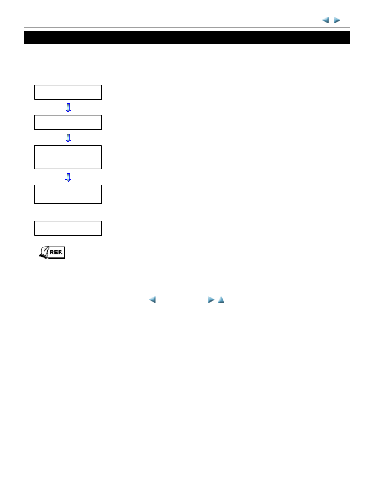
INTRODUCTION
[ How to use this Service Manual ]
This manual is intended to solve printer problems smoothly, with each section representing the typical service
procedures, as shown below.
This manual does not provide sufficient information for disassembly and reassembly procedures. Refer to the
graphics in the separate Parts Catalog.
MX880 series
Troubleshooting
Identify the problem, and handle it accordingly.
Repair
When a part needs to be replaced, see this section.
Adjustment &
Settings
After repair, perform the necessary adjustment and settings.
Verification
At the end of the servicing, verify the machine following the inspection flow in this
section.
Appendix
Information that will be necessary for maintenance and repair of the machine
<INTRODUCTION>

TABLE OF CONTENTS
1. TROUBLESHOOTING
1-1. Troubleshooting by Symptom
1-2. Operator Call Error Troubleshooting
1-3. Service Call Error Troubleshooting
1-4. FAX Error Troubleshooting
2. REPAIR
2-1. Major Replacement Parts and Adjustment
2-2. Disassembly & Reassembly Procedures
(1) External housing, scanner unit, and document cover removal
(2) Operation panel and document feed unit removal
(3) Printer unit removal & Ink absorber replacement
(4) Board removal
(5) Carriage unlocking
(6) ASF unit removal
(7) Carriage unit removal
(8) Spur unit and platen unit removal
(9) Purge drive system unit (right plate) and switch system unit (left plate) removal
(10) Engine unit reassembly
(11) Cable wiring and connection
3. ADJUSTMENT / SETTINGS
3-1. Adjustment
3-2. Adjustment and Maintenance in User Mode
3-3. Adjustment and Settings in Service Mode
(1) Service mode operation procedures
(2) Service Tool functions
(3) LF / Eject correction
(4) Button and LCD test
(5) Ink absorber counter setting
3-4. Adjustment and Maintenance in PTT Parameter Mode
3-5. Grease Application
3-6. Special Notes on Servicing
(1) For smeared printing, uneven printing, or non-ejection of ink
(2) Paper feed motor adjustment
(3) Carriage unit replacement
(4) Document pressure sheet (sponge sheet) replacement
(5) Ink absorber counter setting
(6) Preventive replacement of ink absorber
MX880 series

(7) Power supply unit and modular board replacement
(8) Rating label on the bottom case (except China)
(9) PTT label on the bottom case (for New Zealand only)
(10) Speed Dial Utility
4. VERIFICATION AFTER REPAIR
4-1. Standard Inspection Flow
4-2. Integrated Inspection Pattern Print
4-3. Ink Absorber Counter Value Print
5. APPENDIX
5-1. Customer Maintenance
5-2. Special Tools
5-3. Sensors
5-4. Serial Number Location
6. MACHINE TRANSPORTATION
<TABLE OF CONTENTS>

1. TROUBLESHOOTING
1-1. Troubleshooting by Symptom
MX880 series TABLE OF CONTENTS
Symptom Solution
Faulty
operation
The power does not turn on.
The power turns off
immediately after power-on.
(1) Confirm cable connection:
- PCI DC harness ass'y
=> No incomplete connection, cable breakage, or cable
caught in units
(2) Replace the following item(s):
- Logic board ass'y
- AC adapter
- PCI DC harness ass'y
A strange noise occurs. (1) Examine and remove any foreign material from the drive
portions.
(2) Replace the following item(s):
- The part generating the strange noise
- Purge drive system unit
The LCD does not display
properly.
A portion of the LCD is not
displayed.
The display flickers.
(1) Confirm cable connection:
- LCD cable
=> No incomplete connection, cable breakage, or cable
caught in units
(2) Replace the following item(s):
- LCD ass'y
- LCD cable
- Panel board ass'y
- Logic board ass'y
Paper feed problems (multifeeding, skewed feeding, no
feeding).
(1) Examine and remove any foreign material from the
following parts:
- ASF unit
- PE sensor
- Paper guide unit
- Pressure roller unit
- Spur unit
(2) Confirm that the paper guides are set properly.
(3) Confirm the PF rear cover and the cassette conditions.
(4) Confirm cable connection:
- PE sensor cable
- Paper feed relay harness ass'y
=> No incomplete connection, cable breakage, or cable
caught in units
(5) Replace the following item(s):
- ASF unit (for paper feeding error from the rear tray)
- Pick-up arm unit (for paper feeding error from the cassette)
- PE sensor board ass'y
- Pressure roller unit
1 / 76

- Document feed unit
- Cassette unit
Faulty scanning (no
scanning, strange noise).
(1) Confirm cable connection:
- Scanner motor cable
- CIS FFC
=> No incomplete connection, cable breakage, or cable
caught in units
(2) Confirm the internal conditions under the platen glass (no
damper displaced or caught in units).
(3) Replace the following item(s):
- Scanner unit
- Logic board ass'y
Machine not recognized by a
USB-connected computer.
(1) Confirm the USB cable connection.
(2) Connect the machine to another computer via the USB
cable, and check if the machine is recognized.
(3) Replace the following item(s):
- USB cable
- Logic board ass'y
Unsatisfactory
print quality
No printing, or no color
ejected.
Faint printing, or white lines
on printouts.
Uneven printing.
Improper color hue.
See 3-6. Special Notes on Servicing, (1) For smeared printing,
uneven printing, or non-ejection of ink, for details.
(1) Confirm the ink tank conditions:
- No remainder of the outer film (the air-through must be
opened)
- Whether the ink tank is Canon-genuine one or not
- Whether the ink tank is refilled one or not
- Re-setting of an ink tank
(2) Remove foreign material from the purge unit caps, if any.
(3) Confirm the conditions of the carriage head contact pins.
(4) Perform cleaning or deep cleaning of the print head.
(5) Perform print head alignment.
(6) Replace the following item(s):
- Print head
*1
, and ink tanks
- Logic board ass'y
- Purge drive system unit
- Carriage unit
Paper gets smeared. (1) Clean the inside of the machine.
(2) Perform bottom plate cleaning.
(3) Perform paper feed roller cleaning.
(4) Replace the following item(s):
- Pressure roller ass'y (if smearing is heavy)
- Print head
*1
(when smearing is caused by the print head)
The back side of paper gets
smeared.
(1) Clean the inside of the machine.
(2) Perform bottom plate cleaning.
(3) Examine the platen ink absorber.
(4) Examine the paper eject roller.
(5) Replace the following item(s):
2 / 76

*1: Replace the print head only after the print head deep cleaning is performed 2 times, and when the
problem persists.
- The part in the paper path causing the smearing
Graphic or text is enlarged on
printouts in the carriage
movement direction.
(1) Confirm that the carriage slit film is free from smearing or
scratches:
- Cleaning of the timing slit strip film.
(2) Replace the following item(s):
- Timing slit strip film
- Carriage unit
- Logic board ass'y
- Scanner unit (for copying)
Graphic or text is enlarged on
printouts in the paper feed
direction.
(1) Confirm that the LF / EJ slit film is free from smearing or
scratches:
- Cleaning of the LF / EJ slit film.
(2) Replace the following item(s):
- Timing slit disk feed film
- Timing slit disk eject film
- Timing sensor unit
- Platen unit
- Logic board ass'y
- Scanner unit (for copying)
Faulty
scanning
No scanning. (1) Confirm cable connection.
(2) Replace the following item(s):
- Scanner unit
- Logic board ass'y
Streaks or smears on the
scanned image.
(1) Clean the platen glass and the document pressure sheet.
(2) Confirm the position of the document pressure sheet.
(3) Replace the following item(s):
- Scanner unit
- Document pressure sheet
- Logic board ass'y
Network
connection
problem
No printing. (1) Examine if printing is performed properly via USB
connection.
(2) Confirm the network connection.
(3) Replace the following item(s):
- Logic board ass'y
- Wireless LAN board ass'y
FAX problem No FAX sending or
reception.
(1) Confirm the FAX settings.
(2) Replace the following item(s):
- NCU board ass'y
- Logic board ass'y
3 / 76

1-2. Operator Call Error (by Alarm LED Lit in Orange) Troubleshooting
Errors and warnings are displayed by the following ways:
1. Operator call errors are indicated by the Alarm LED lit in orange, and the error and its solution are displayed
on the LCD in text and by icon.
2. Messages during printing from a PC are displayed on the printer driver Status Monitor.
3. Error codes (the latest 10 error codes at the maximum) are printed in the "operator call/service call error
record" area in EEPROM information print
Buttons valid when an operator call error occurs:
1. ON button: To turn the machine off and on again.
2. OK button: To clear and recover from an error. In some operator call errors, the error will automatically be
cleared when the cause of the error is eliminated, and pressing the OK button may not be
necessary.
3. Stop button: To cancel the job at error occurrence, and to clear the error.
Error
Error
codeU No.
Message on the
LCD
Solution
Parts that are likely to
be faulty
No paper in the
rear tray.
[1000] --- Rear tray.
There is no paper.
Load paper and press
[OK].
Confirm that the rear tray
is selected as the paper
source. Set the paper in the
rear tray, and press the OK
button.
If the error is not cleared,
confirm that no foreign
material is inside the paper
feed slot.
- PE sensor board ass'y
- ASF unit
- Pressure roller unit
No paper in the
cassette.
[1003] --- Cassette.
There is no paper.
Load paper and press
[OK].
Confirm that the cassette is
selected as the paper
source. Set the paper in the
cassette, and press the OK
button.
Note that the cassette is for
plain paper only.
- Pick-up arm unit
- Pressure roller ass'y
- Cassette unit
Paper jam. [1300] --- The paper is jammed.
Clear the paper and
press [OK].
Remove the jammed paper
and press the OK button.
For paper jam in the rear
guide, confirm that the rear
guide is not dislocated.
- Pick-up arm unit
- ASF unit
- Pressure roller ass'y
- Cassette unit
- Rear guide unit
Paper jam in
the rear guide.
[1303] ---
Paper jam in
the under guide.
[1304] ---
Ink may have
run out.
[1600] U041 The ink may have run
out. Replacing the ink
tank is recommended.
Replace the applicable ink
tank, or press the OK
button to clear the error
without ink tank
replacement. When the
error is cleared by pressing
the OK button, ink may
- Spur unit
4 / 76

run out during printing.
Ink tank not
installed.
[1660] U043 The following ink
tank cannot be
recognized.
(Applicable ink tank
icon)
Install the applicable ink
tank(s) properly, and
confirm that the LED's of
all the ink tanks light red.
- Ink tank
- Carriage unit
Print head not
installed, or not
properly
installed.
[1401] U051 Print head is not
installed. Install the
print head.
Install the print head
properly.
If the error is not cleared,
confirm that the print head
contact pins of the carriage
are not bent.
- Print head
- Carriage unit
Faulty print
head ID.
U052 The type of print head
is incorrect. Install the
correct print head.
Re-set the print head. If the
error is not cleared, the
print head may be
defective. Replace the print
head. If the error is not
cleared, confirm that the
print head contact pins of
the carriage are not bent.
- Print head
- Carriage unit
Print head
temperature
sensor error.
[1403]
Faulty
EEPROM data
of the print
head.
[1405]
Multiple ink
tanks of the
same color
installed.
[1487] U071 More than one ink
tank of the following
color is installed.
Replace the wrong ink tank
(s) with the correct one(s).
- Ink tank
Ink tank in a
wrong position.
[1680] U072 Some ink tanks are
not installed in place.
Install the ink tank(s) in
the correct position.
- Ink tank
Warning: The
ink absorber
becomes almost
full.
[1700] --- The ink absorber is
almost full. Press
[OK] to continue
printing. Contact the
service center.
Replace the ink absorber,
and reset its counter. [See
3-3, Adjustment and
Settings in Service Mode.]
Pressing the OK button
will exit the error, and
enable printing without
replacing the ink absorber.
However, when the ink
absorber becomes full, no
further printing can be
performed unless the
applicable ink absorber is
replaced.
- Absorber kit
The connected
digital camera
or digital video
camera does not
[2001] --- Incompatible device
detected. Remove the
device.
Remove the cable between
the camera and the
machine.
5 / 76

support Camera
Direct Printing.
Automatic
double-sided
printing cannot
be performed.
[1310] --- This paper is not
compatible with twosided printing.
Remove the paper and
press [OK].
The paper length is not
supported for double-sided
printing.
Press the OK button to
eject the paper being used
at error occurrence.
Data which was to be
printed on the back side of
paper at error occurrence is
skipped (not printed).
- Duplex paper feed
roller unit
- PE sensor board ass'y
Failed in
automatic print
head alignment.
[2500] --- Auto head align has
failed. Press [OK] and
repeat operation. <See
manual>
Press the OK button to
clear the error, then
perform the automatic
print head alignment again.
(Use Matte Photo Paper
MP-101.)
If the alignment pattern
was not printed properly
(faint printing, etc.),
perform print head
cleaning, then perform the
print head alignment
again.
- Carriage unit
- Print head
- Purge drive system
unit
The remaining
ink amount
unknown (raw
ink present).
[1683] U130 The remaining level
of the ink cannot be
correctly detected.
Replace the ink tank.
An ink tank which has
once been empty is
installed. Replace the
applicable ink tank with a
new one. Printing with a
once-empty ink tank can
damage the machine.
To continue printing
without replacing the ink
tank(s), press the Stop
button for 5 sec. or longer
to disable the function to
detect the remaining ink
amount. After the
operation, it is recorded in
the machine EEPROM that
the function to detect the
remaining ink amount was
disabled.
- Ink tank
- Spur unit
Ink tank not
recognized.
[1684] U140 The following ink
tank cannot be
recognized.
An incompatible ink tank
is installed (the ink tank
LED is turned off). Install
- Ink tank
6 / 76

(Applicable ink tank
icon)
the supported ink tanks.
Ink tank not
recognized.
[1750] U141 Appropriate ink tank
is not installed. Install
the appropriate ink
tank.
A non-supported ink tank
is installed (the ink tank
LED is turned off). Install
the supported ink tanks.
- Ink tank
Ink tank not
recognized.
[1682] U150 The following ink
tank cannot be
recognized.
(Applicable ink tank
icon)
A hardware error occurred
in an ink tank (the ink tank
LED is turned off).
Replace the ink tank(s).
- Ink tank
No ink (no raw
ink).
[1688] U163 The ink has run out.
Replace the ink tank.
(Applicable ink tank
icon)
Replace the empty ink tank
(s), and close the scanning
unit (cover).
Printing with an empty ink
tank can damage the
machine.
To continue printing
without replacing the ink
tank(s), press the Stop
button for 5 sec. or longer
to disable the function to
detect the remaining ink
amount. After the
operation, it is recorded in
the machine that the
function to detect the
remaining ink amount was
disabled.
- Ink tank
- Spur unit
Non-supported
hub.
[2002] --- An unsupported USB
hub is connected.
Remove the hub.
Remove the applicable
USB hub from the
PictBridge (USB)
connector.
Document
feeder cover not
closed.
[2800] --- The feeder cover is
open. Close cover and
press [OK].
Close the document feeder
cover, and press the OK
button.
- DF unit
- DF switch unit
Paper jam in
the ADF.
[2801] --- Document in ADF.
Check document in
ADF, then press [OK]
and redo operation.
Remove the paper from the
ADF, and press the OK
button.
- DF unit
No paper in the
ADF.
[2802] --- No document in ADF.
Press [OK], then load
document and redo
operation.
Press the OK button to
clear the error.
- DF unit
Paper in the [2803] --- Document size is too Remove the paper from the - DF unit
7 / 76

1-3. Service Call Error (by Cyclic Blinking of Alarm and Power LEDs) Troubleshooting
Service call errors are indicated by the number of cycles the Alarm and Power LEDs blink, and the corresponding
error code with the message, "Printer error has occurred. Turn off power then back on again. If problem persists,
see the manual." is displayed on the LCD.
1) Check each point in "Check points & Solution," and perform the solution if it applies.
2) When no solution in "Check points & Solution" is effective, then replace the part listed under "Parts to that
are likely to be faulty" one by one from the one most likely to be faulty. The parts are listed in the order of
likeliness to be faulty.
ADF is too
long.
long. Check document
in ADF, then press
[OK] and redo
operation..
ADF, and press the OK
button.
Double-sided
printing not
available with
the paper in the
ADF.
[2804] --- Document size not
suitable for duplex
scanning. Press [OK]
to cancel operation
and eject document.
Remove the paper from the
ADF, and press the OK
button.
- DF unit
Time-out for
the scanner
device.
[2700] --- Timeout error has
occurred. Press [OK].
The buffer became full in
the middle of scanning
operation, and 60 minutes
have elapsed since then,
making re-scanning
unstable. Press the OK
button to clear the error.
Premium
Contents print
error.
[4100] --- Cannot print the data. Non-genuine ink tanks are
installed. Install the
supported (Canon-genuine)
ink tanks.
- Ink tank
Cycles
of
blinking
of
Alarm
and
Power
LEDs
Error
Error
code
Check points & Solution
Parts that are likely
to be faulty (listed
in the order of
likeliness to be
faulty)
2 times Carriage error [5100] (1) Smearing or scratches on the carriage
slit film:
Clean the film using lint-free paper.
(2) Foreign material that obstructs the
carriage movement:
Remove foreign material.
(3) Ink tank conditions:
Re-set the ink tanks.
(4) Cable connection:
- CR FFC (J500, J501, J502, etc.)
- Timing slit strip film
- Carriage unit
- Logic board ass'y
- Carriage motor
8 / 76

Re-connect the cables.
(5) Scratches or damages to the carriage slit
film:
Replace the timing slit strip film.
(6) Black debris around the carriage rail or
pressure roller:
Replace the carriage unit.
3 times Line feed error [6000] (1) Opening and closing of the paper output
tray:
Remove obstacles from around the
paper output tray so that the tray
opens and closes properly.
(2) Smearing or scratches on the LF / EJ
slit film:
Clean the LF / EJ slit film using
lint-free paper.
(3) Foreign material in the LF drive:
Remove foreign material.
(4) Cable connection
Re-connect the cables.
If any damage or breakage of the
cable is found, replace the cable.
(5) LF lock arm spring:
Attach the spring properly.
- Timing slit disk feed
film
- Timing slit disk eject
film
- Timing sensor unit
- Paper feed roller unit
- Logic board ass'y
- Paper feed motor
4 times Purge cam sensor
error
[5C00] (1) Foreign material around the purge drive
system unit:
Remove foreign material.
(2) Cable connection:
- LF encoder cable
- PE sensor cable
- Paper feed motor harness ass'y
Re-connect the cable.
(3) Strange sound at power-on:
Replace the purge drive system unit.
- Purge drive system
unit
- Logic board ass'y
5 times ASF (cam) sensor
error
[5700] (1) Cable connection:
- PE sensor cable, etc.
Re-connect the cable.
- ASF unit
- PE sensor board
ass'y
- Logic board ass'y
6 times Internal temperature
error
[5400] (1) Cable connection:
- Between the spur unit and the logic
board, J703 connector, etc.
Re-connect the cable.
- Spur unit
- Logic board ass'y
- Print head
7 times Ink absorber full [5B00]
[5B01]
(1) Ink absorber condition:
Replace the ink absorber, and reset
the ink absorber counter value in the
EEPROM.
- Absorber kit
9 / 76

8 times Print head
temperature rise error
[5200] (1) Print head condition (face surface and
mold):
If a burn mark or heat deformation
is seen on the face surface or the
mold, replace the print head.
(2) Head contact pin condition of the
carriage unit:
If the pin is bent or deformed,
replace the carriage unit.
(3) Cable connection:
- CR FFC (J500, J501, J502)
Re-connect the cable.
If any damage or breakage of the
cable is found, replace the carriage
unit.
- Print head
- Carriage unit
9 times EEPROM error [6800]
[6801]
(1) Part replacement:
Replace the logic board ass'y.
- Logic board ass'y
10 times VH monitor error [B200] (1) Print head condition (face surface and
mold):
If a burn mark or heat deformation
is seen on the face surface or the
mold, replace the print head and the
logic board in set. (Be sure to
replace them at the same time.)
(2) Burn mark or heat deformation of the
logic board:
If a burn mark or heat deformation
is seen on the logic board, replace
the print head and the logic board in
set. (Be sure to replace them at the
same time.)
(3) Head contact pin condition of the
carriage unit:
If the pin is bent or deformed,
replace the carriage unit.
(4) Cable connection:
- CR FFC (J502, J501, J500)
Re-connect the cable.
If any damage or breakage of the
cable is found, replace the carriage
unit.
- Print head and logic
board ass'y (replace
them at the same
time)
- AC adapter
- Carriage unit
11 times Carriage lift
mechanism error
[5110] (1) Foreign material that obstructs the
carriage movement:
Remove foreign material.
- Switch system unit
- Carriage unit
12 times APP position error [6A80] (1) Cap absorber and wiper blade of the
purge drive system unit:
If the cap absorber contacts the
- Purge drive system
unit
- Logic board ass'y
10 / 76

APP position error
during initial purging
[6A81] wiper blade, lower the cap absorber
so that it will not contact the wiper
blade.
(2) Foreign material around the purge drive
system unit:
Remove foreign material.
(3) Ink absorber right beneath the purge
drive system unit:
Confirm that the absorber stays in
place and does not contact the unit.
(4) Foreign material around the ASF unit:
Remove foreign material.
(5) Cable connection:
- PE sensor cable
- Motor multi harness ass'y
Re-connect the cables.
If any damage or breakage of the
cable is found, replace the cable.
(6) APP slit film condition:
Clean the APP slit film using lintfree paper.
(7) APP code wheel gear condition:
If the gear wears, replace the gear.
14 times APP sensor error [6A90]
Paper feed cam
sensor error
[6B10] (1) Ink absorber counter value:
If the value exceeds 60%, replace
the ink absorber. Follow the
"Guideline for Preventive
Replacement of the Ink Absorber."
(2) Jammed paper in the under guide:
Remove the jammed paper.
- Pick-up arm unit
- Duplex paper feed
roller unit
15 times USB host Vbus
overcurrent
[9000] (1) Part replacement:
Replace the logic board ass'y.
16 times Pump roller sensor
error
[5C20] (1) Cable connection
Re-connect the cable.
- Purge drive system
unit
17 times Paper eject encoder
error
[6010] (1) Smearing on the LF / EJ slit film:
Clean the LF / EJ slit film using
lint-free paper.
(2) Foreign material in the paper path:
Remove foreign material.
(3) Cable connection:
- LF encoder cable
- PE sensor cable
Re-connect the cable.
(4) Scratches on the LF / EJ slit film:
Replace the timing slit disk feed
film or the timing slit disk eject
film.
- Timing slit disk feed
film
- Timing slit disk eject
film
- Timing sensor unit
- Platen unit
- Logic board ass'y
- Paper feed motor
11 / 76

19 times Ink tank position
sensor error
[6502] (1) Ink tank position:
Confirm the ink tanks are installed
in the correct slots.
(2) Re-set or replacement of ink tanks:
If the error persists, replace the ink
tanks.
(3) Cable connection
Re-connect the cable.
- Spur unit
- Logic board ass'y
20 times Other errors [6500] (1) Cable connection:
- Wireless LAN cable
Re-connect the cable.
- Logic board ass'y
- Wireless LAN board
ass'y
21 times Drive switch error [C000] (1) Foreign material in the drive switch
area of the purge drive system unit:
Remove foreign material.
(2) Ink tank conditions:
Confirm that the ink tanks are
seated properly and they do not
interfere with the carriage
movement.
- Purge drive system
unit
- ASF unit
- Carriage unit
22 times Scanner error [5011] (1) Cable connection:
- J900, J1103, J704
Re-connect the cable.
(2) Damper condition inside the scanner:
If the damper winds around the CIS,
replace the scanner unit.
(3) Scanner belt pulley:
If the pulley is dislocated, replace
the scanner unit.
(4) Document pressure sheet conditions:
Re-attach the document pressure
sheet, or replace it.
- Scanner unit
- Document pressure
sheet
- Logic board ass'y
FB motor error [5012] (1) Cable connection:
- J900, J1103, J704
Re-connect the cable.
- Scanner unit
23 times Valve cam sensor
error
[6C10] (1) Foreign material around the purge drive
system unit:
Remove foreign material.
(2) Cable connection:
- J702 connector
Re-connect the cable.
- Purge drive system
unit
- Logic board ass'y
Before replacement of the logic board, check the ink absorber counter value, and register it to
the replaced new logic board. (The value can be set in 10% increments.) In addition,
according to the "Guideline for Preventive Replacement of Ink Absorber," replace the ink
absorber. [See 3. ADJUSTMENT / SETTINGS, 3-3. Adjustment and Settings in Service
Mode, for details.]
12 / 76
1-4. FAX Error Troubleshooting
For errors other than those listed below, please refer to the "G3 / G4 Facsimile Error Code List (Rev. 2." (HY823A0-020 in English, HY8-22A6-020 in Japanese).
(1) User error codes
(2) Service error codes
Error
code
TX / RX Meaning
Solution
(Parts that are likely to be faulty)
#001 TX Document jam - DF unit
#003 TX / RX Document is too long, or page time-over - DF unit
#005 TX / RX Initial identification (T0 / T1) time-over - Check the telephone line type settings
(rotary pulse / touch tone).
#009 RX Recording paper jam, or no recording paper - ASF unit
- Pick-up arm unit
- Cassette unit
- Pressure roller unit
#012 TX No recording paper at the receiving machine
#017 TX Redial time-over, but no DT detected
#018 TX Auto dialing transmission error, or redial time-
over
- Check the telephone line type settings
(rotary pulse / touch tone).
#022 TX Call failed (no dial registration) - Register a dial number.
#037 RX Memory overflow at reception of an image - Delete unnecessary image data from the
memory.
#085 TX No color fax function supported in the
receiving machine
- Send a fax in the B&W mode.
#099 TX / RX Transmission terminated mid-way by pressing
the Stop button
#995 TX / RX During TX (sending): Memory transmission
reservation cancelled
During RX (receiving): Image data received
in the memory cleared
Error
code
TX / RX Meaning
Solution
(Parts that are likely to be faulty)
##100 TX Re-transmission of the procedure signal has been
attempted the specified number of times, but
failed.
- Try a higher transmission level.
##101 TX / RX Sender's modem speed does not match the
receiving machine.
##102 TX Fallback is not available. - Try a higher transmission level.
##103 RX EOL has not been detected for 5 seconds (or 15 - Increase the transmission level of the
13 / 76

seconds in CBT). sending machine.
##104 TX RTN or PIN has been received. - Try a higher transmission level.
##106 RX The procedure signal has been expected for 6
seconds, but not received.
- Increase the transmission level of the
sending machine.
##107 RX Fallback is not available at the sending machine. - Increase the transmission level of the
sending machine.
##109 TX After DCS transmission, a signal other than DIS,
DTC, FTT, CFR, or CRP has been received, and
re-transmission of the procedure signal has been
attempted the specified number of times but
failed.
##111 TX / RX Memory error - Eliminate all the data, and register them
again.
##114 RX RTN has been received. - Increase the transmission level of the
sending machine.
##200 RX A carrier has not been detected for 5 seconds
during image reception.
- Increase the transmission level of the
sending machine.
##201 TX / RX DCN has been received in a method other than
the binary procedure.
- Set the other machine ready for
reception.
##204 TX DTC has been received even when there is no
sending data.
##220 TX / RX System error (main program hang-up) - Turn the machine off, and turn it on
again
- Modular board
- Logic board
##224 TX / RX An error has occurred in the procedure signal in
G3 transmission.
##226 TX / RX The stack pointer has shifted from the RAM area. - Turn the machine off, and turn it on
again.
##229 RX The recording area has been locked for 1 minute. - After the area is unlocked, print the
recorded image.
##232 TX The encoder control unit has malfunctioned. - Modular board
- Logic board
##237 RX The decoder control unit has malfunctioned. - Modular board
- Logic board
##238 RX The print control unit has malfunctioned. - Modular board
- Logic board
##261 TX / RX A system error has occurred between the modem
and the system control board.
- Modular board
- Logic board
##280 TX Re-transmission of the procedure signal has been
attempted the specified number of times, but
- Try a higher transmission level.
14 / 76

failed.
##281 TX Re-transmission of the procedure signal has been
attempted the specified number of times, but
failed.
- Try a higher transmission level.
##282 TX Re-transmission of the procedure signal has been
attempted the specified number of times, but
failed.
- Try a higher transmission level.
##283 TX Re-transmission of the procedure signal has been
attempted the specified number of times, but
failed.
- Try a higher transmission level.
##284 TX After TCF transmission, DCN has been received. - Set the receiving machine ready for
reception.
##285 TX After EOP transmission, DCN has been received. - Re-send the fax.
##286 TX After EOM transmission, DCN has been
received.
- Re-send the fax.
##287 TX After MPS transmission, DCN has been received. - Re-send the fax.
##288 TX After EOP transmission, a signal other than PIN,
PIP, MCF, RTP, RTN has been received.
##289 TX After EOM transmission, a signal other than PIN,
PIP, MCF, RTP, RTN has been received.
##290 TX After MPS transmission, a signal other than PIN,
PIP, MCF, RTP, RTN has been received.
##670 TX In V.8 late start, the DIS V.8 ability from the
receiving machine was detected, and CI was sent
in response; however, the procedure failed,
causing T1 time-over.
- In bit 0 of the service data #1 SSSW
SW28, prohibit the V.8 / V.34
procedure of the sending machine.
##671 RX In V.8 call reception, the procedure fails to
proceed to phase 2 after CM detection, causing
T1 time-over.
- In bit 0 of the service data #1 SSSW
SW28, prohibit the V.8 / V.34
procedure of the sending machine.
##672 TX In V.34 transmission, the procedure fails to
proceed from phase 2 to phase 3 or later, causing
T1 time-over
- In bit 0 of the service data #1 SSSW
SW28, prohibit the V.8 / V.34
procedure of the sending machine.
##673 RX In V.34 reception, the procedure fails to proceed
from phase 2 to phase 3 or later, causing T1 timeover
- In bit 0 of the service data #1 SSSW
SW28, prohibit the V.8 / V.34
procedure of the sending machine.
##674 TX In V.34 transmission, the procedure fails to
proceed from phase 3 or 4 to the control channel
or later, causing T1 time-over
- In bit 0 of the service data #1 SSSW
SW28, prohibit the V.8 / V.34
procedure of the sending machine.
##675 RX In V.34 reception, the procedure fails to proceed
from phase 3 or 4 to the control channel or
further, causing T1 time-over
- In bit 0 of the service data #1 SSSW
SW28, prohibit the V.8 / V.34
procedure of the sending machine.
##750 TX After transmitting PPS-NULL in ECM - Try a higher transmission level.
15 / 76

transmission, no significant signal has been
received, and re-transmission of the procedure
signal has been attempted the number of
specified times but failed.
##752 TX After transmitting PPS-NULL in ECM
transmission, DCN has been received.
- Try a higher transmission level.
##753 TX After transmitting PPS-NULL in ECM
transmission, re-transmission of the procedure
signal has been attempted the number of
specified times but failed, or T5 time-over (60
sec.) has occurred.
- Increase the period of time of the T5
time-over.
##754 TX After transmitting PPS-NULL in ECM
transmission, re-transmission of the procedure
signal has been attempted the number of
specified times but failed.
- Try a higher transmission level.
##755 TX After transmitting PPS-MPS in ECM
transmission, no significant signal has been
received, and re-transmission of the procedure
signal has been attempted the number of
specified times but failed.
- Try a higher transmission level.
##757 TX After transmitting PPS-MPS in ECM
transmission, DCN has been received.
- Try a higher transmission level.
##758 TX After transmitting PPS-MPS in ECM
transmission, re-transmission of the procedure
signal has been attempted the number of
specified times but failed, or T5 time-over (60
sec.) has occurred.
- Increase the period of time of the T5
time-over.
##759 TX After transmitting PPS-MPS in ECM
transmission, re-transmission of the procedure
signal has been attempted the number of
specified times but failed.
- Try a higher transmission level.
##760 TX After transmitting PPS-EOM in ECM
transmission, no significant signal has been
received, and re-transmission of the procedure
signal has been attempted the number of
specified times but failed.
- Try a higher transmission level.
##762 TX After transmitting PPS-EOM in ECM
transmission, DCN has been received.
- Try a higher transmission level.
##763 TX After transmitting PPS-EOM in ECM
transmission, re-transmission of the procedure
signal has been attempted the number of
specified times but failed, or T5 time-over (60
sec.) has occurred.
- Increase the period of time of the T5
time-over.
##764 TX After transmitting PPS-EOM in ECM - Try a higher transmission level.
16 / 76

transmission, re-transmission of the procedure
signal has been attempted the number of
specified times but failed.
- Increase the transmission level of the
receiving machine.
##765 TX After transmitting PPS-EOP in ECM
transmission, no significant signal has been
received, and re-transmission of the procedure
signal has been attempted the number of
specified times but failed.
- Try a higher transmission level.
- Increase the transmission level of the
receiving machine.
##767 TX After transmitting PPS-EOP in ECM
transmission, DCN has been received.
- Try a higher transmission level.
##768 TX After transmitting PPS-EOP in ECM
transmission, re-transmission of the procedure
signal has been attempted the number of
specified times but failed, or T5 time-over (60
sec.) has occurred.
- Increase the period of time of the T5
time-over.
##769 TX After transmitting PPS-EOP in ECM
transmission, re-transmission of the procedure
signal has been attempted the number of
specified times but failed.
- Try a higher transmission level.
- Increase the transmission level of the
receiving machine.
##770 TX After transmitting EOR-NULL in ECM
transmission, no significant signal has been
received, and re-transmission of the procedure
signal has been attempted the number of
specified times but failed.
- Try a higher transmission level.
- Increase the transmission level of the
receiving machine.
##772 TX After transmitting EOR-NULL in ECM
transmission, DCN has been received.
- Try a higher transmission level.
##773 TX After transmitting EOR-NULL in ECM
transmission, re-transmission of the procedure
signal has been attempted the number of
specified times but failed, or T5 time-over (60
sec.) has occurred.
- Increase the period of time of the T5
time-over.
##774 TX After transmitting EOR-NULL in ECM
transmission, ERR has been received.
- Try a higher transmission level.
##775 TX After transmitting EOR-MPS in ECM
transmission, no significant signal has been
received, and re-transmission of the procedure
signal has been attempted the number of
specified times but failed.
- Try a higher transmission level.
##777 TX After transmitting EOR-MPS in ECM
transmission, DCN has been received.
- Try a higher transmission level.
##778 TX After transmitting EOR-MPS in ECM
transmission, re-transmission of the procedure
signal has been attempted the number of
specified times but failed, or T5 time-over (60
- Increase the period of time of the T5
time-over.
17 / 76

sec.) has occurred.
##779 TX After transmitting EOR-MPS in ECM
transmission, ERR has been received.
- Try a higher transmission level.
##780 TX After transmitting EOR-EOM in ECM
transmission, no significant signal has been
received, and re-transmission of the procedure
signal has been attempted the number of
specified times but failed.
- Increase the transmission level of the
receiving machine.
##782 TX After transmitting EOR-EOM in ECM
transmission, DCN has been received.
- Increase the transmission level of the
receiving machine.
##783 TX After transmitting EOR-EOM in ECM
transmission, re-transmission of the procedure
signal has been attempted the number of
specified times but failed, or T5 time-over (60
sec.) has occurred.
- Increase the period of time of the T5
time-over.
##784 TX After transmitting EOR-EOM in ECM
transmission, ERR has been received.
- Try a higher transmission level.
##785 TX After transmitting EOR-EOP in ECM
transmission, no significant signal has been
received, and re-transmission of the procedure
signal has been attempted the number of
specified times but failed.
- Try a higher transmission level.
- Increase the transmission level of the
receiving machine.
##787 TX After transmitting EOR-EOP in ECM
transmission, DCN has been received.
- Try a higher transmission level.
##788 TX After transmitting EOR-EOP in ECM
transmission, re-transmission of the procedure
signal has been attempted the number of
specified times but failed, or T5 time-over (60
sec.) has occurred.
- Increase the period of time of the T5
time-over.
##789 TX After transmitting EOR-EOP in ECM
transmission, ERR has been received.
- Try a higher transmission level.
##790 RX After receiving EOR-EOP in ECM reception,
ERR has been transmitted.
- Increase the transmission level of the
sending machine.
##791 TX / RX During the ECM mode procedure, a signal other
than a significant one has been received.
##792 RX In ECM reception, PPS-NULL between partial
pages has not been detected.
- Increase the transmission level of the
sending machine.
##793 RX During high-speed signal reception in ECM, no
effective frame has been detected, and a timeover has occurred.
- Try a higher transmission level.
- Increase the transmission level of the
sending machine.
<1. TROUBLESHOOTING>
18 / 76

2. REPAIR
2-1. Major Replacement Parts and Adjustment
MX880 series TABLE OF CONTENTS
Service
part
Recommended removal procedure*1 /
Notes on replacement
Adjustment / settings / operation check
Logic
b
oard ass'y
(1) Cassette unit
(2) Left and right side covers
(3) Document pressure plate unit
(4) Scanner unit
(5) Main case
(6) Rear cover
(7) Logic board ass'y
- Before replacement, check the ink
absorber counter value (by service test
print or EEPROM information print).
- Before removal of the logic board ass'y,
remove the power cord, and allow for
approx. 1 minute (for discharge of
capacitor's accumulated charges), to
prevent damages to the logic board ass'y.
In the service mode:
1. Set the ink absorber counter value.
2. Set the destination.
3. Print the integrated inspection pattern.
4. Perform LF / Eject correction (only when
streaks or uneven printing occurs).
5. Print the EEPROM information.
[See 3-3. Adjustment and Settings in Service
Mode, for details.]
In the user mode:
6. Set the language displayed on the LCD.
7. Reset the LAN settings.
8. Perform print head alignment.
9. Print via USB connection.
10. Copy.
11. Perform direct printing from a digital camera
(PictBridge).
Absorber
kit
(1) Cassette unit
(2) Left and right side covers
(3) Document pressure plate unit
(4) Scanner unit
(5) Main case
(6) Rear cover
(7) Print unit
(8) Ink absorber
- See 2-2. Disassembly & Reassembly
Procedures, (3) Printer unit removal & Ink
absorber replacement, for details.
In the service mode:
1. Reset the ink absorber counter.
After the ink absorber counter is reset, the
counter value is printed automatically
[See 3-3. Adjustment and Settings in Service
Mode, for details.].
Carriage
unit
(1) Cassette unit
(2) Left and right side covers
(3) Document pressure plate unit
(4) Scanner unit
(5) Main case
(6) Rear cover
(7) Timing slit strap
- Before removal of the carriage rail, put a
mark of the carriage rail position.
(8) Carriage rail
(9) Carriage unit
1. Apply grease to the sliding portions of the
carriage rail.
[See 3-5. Grease Application, for details.]
In the service mode:
2. Print the integrated inspection pattern.
[See 3-3. Adjustment and Settings in Service
Mode, for details.]
In the user mode:
3. Perform automatic print head alignment.
19 / 76
 Loading...