

Canon MP830 - PIXMA Color Inkjet Service Manual

PIXMA MP830
SER VICE
MANUAL
Copyright 2006, Canon U.S.A. This technical publication is the proprietary and confidential information of Canon U.S.A. which
shall be retained for reference purposes by Authorized Service Facilities of Canon U.S.A. Its unauthorized use is prohibited.
Canon

Trademarks
Product and brand names appearing in this manual are registered trademarks or trademarks of the respective holders.
Copyright
All rights reserved. No parts of this manual may be reproduced in any form or by any means or translated into another language without the written
permission of Canon Inc., except in the case of internal business use.
Copyright © 2006 by Canon Inc.
CANON INC.
Inkjet Device Quality Assurance Div. 2
451, Tsukagoshi 3-chome, Saiwai-ku, Kawasaki-shi, Kanagawa 212-8530, Japan

I. MANUAL OUTLINE
This manual consists of the following three parts to provide information necessary to service the PIXMA MP830:
Part 1: Maintenance
Information on maintenance and troubleshooting of the PIXMA MP830
Part 2: Technical Reference
N
ew technology and technical information such as FAQ's (Frequently Asked Questions) of the PIXMA MP830
Part 3: Appendix
Block diagrams and pin layouts of the PIXMA MP830
Reference:
This manual does not provide sufficient information for disassembly and reassembly procedures. Refer to the graphics in the separate Parts Catalog.

II. TABLE OF CONTENTS
Part 1: MAINTENANCE
1. MAINTENANCE
1-1. Adjustment, Periodic Maintenance, Periodic Replacement Parts, and Replacement Consumables by Service Engineer
1-2. Customer Maintenance
1-3. Product Life
1-4. Special Tools
1-5. Serial Number Location
2. LIST OF ERROR DISPLAY / INDICATION
2-1. Operator Call Errors
2-2. Service Call Errors
2-3. Fax Errors
2-4. Other Error Messages
2-5. Warnings
2-6. Troubleshooting by Symptom
3. REPAIR
3-1. Notes on Service Part Replacement (and Disassembling / Reassembling)
3-2. Special Notes on Repair Servicing
(1) Power supply unit removal / reassembly
(2) Cassette, front door (paper output tray), and door damper removal
(3) Emblem removal
(4) Side cover (right and left) removal
(5) Front cover (right and left) removal
(6) DF front cover removal
(7) DF rear cover removal
(8) Stop arm removal
(9) DF grip cover and DF right cover removal
(10) Document feed unit removal
(11) Separation tab, document feed roller, and separation roller cleaning
(12) DF cable cover removal
(13) ADF hinge removal
(14) Operation panel (right and left) removal
(15) LCD upper cover removal
(16) Operation panel unit removal
(17) LCD unit removal
(18) Logic board ass'y wiring
(19) Scanner stop arm removal
(20) Scanner stopper removal
(21) Cable holder sheet position
(22) Scanner unit removal
(23) Main case unit removal
(24) Base case and printer unit wiring
(25) Logic board ass'y removal
(26)
Printer unit removal

3-3. Adjustment / Settings
(1) Paper feed motor adjustment
(2) Grease application
(3) Waste ink counter setting
(4) White sponge sheet attachment
(5) User mode
(6) Service mode
Service mode operation
Destination settings
LF correction
Waste ink amount setting
Button and LCD test
3-4. Verification Items
(1) Service test print
(2) EEPROM information print
(3) Fax report
4. MACHINE TRANSPORTATION
Part 2: TECHNICAL REFERENCE
1. NEW TECHNOLOGIES
2. CLEANING MODE AND AMOUNT OF INK PURGED
3. PRINT MODE
3-1. Normal Color Printing via Computer
3-2. Normal Grayscale Printing via Computer
3-3. Borderless Printing via Computer
3-4. Duplex Printing via Computer
3-5. Camera Direct Printing
3-6. Card Direct Printing
3-7. Copying
4. FAQ (Problems Specific to the MP830 and Corrective Actions)
Part 3: APPENDIX
1. BLOCK DIAGRAM
2. CONNECTOR LOCATION AND PIN LAYOUT
2-1. Logic Board Ass'y
2-2. NCU Board
2-3. Relay Board
2-4. Card Slot Board
2-5. Operation Panel Board
2-6. Carriage Board (Print Head Connector)
3. PIXMA MP830 SPECIFICATIONS

P
art 1
MAINTENANCE
1. MAINTENANCE
1-1. Adjustment, Periodic Maintenance, Periodic Replacement Parts, and Replacement Consumables by
Service Engineer
(1) Adjustment
Note: DO NOT loosen the red screws at both ends of the carriage shaft, securing the print head position, as they are not re-adjustable.
The red screws securing the paper feed motor may be loosened only at replacement of the paper feed motor unit.
*1: Only for CD / DVD printing supported regions.
(2) Periodic maintenance
No periodic maintenance is necessary.
(3) Periodic replacement parts
There are no parts in this machine that require periodic replacement by a service engineer.
(4) Replacement consumables
There are no consumables that require replacement by a service engineer.
1-2. Customer Maintenance
Adjustment Timing Purpose Tool
Approx.
time
EEPROM initialization At logic board replacement
To initialize settings.
None.
1 min.
Destination settings
(EEPROM settings)
At logic board replacement
To set the destination.
None.
Perform in the service
mode.
1 min.
Waste ink counter
resetting
(EEPROM settings)
- At logic board replacement
- At waste ink absorber replacement
To reset the waste ink counter.
None.
Perform in the service
mode.
1 min.
Waste ink amount
setting
(EEPROM settings)
- At logic board replacement
To set the waste ink amount to the waste ink
counter.
None.
Perform in the service
mode.
1 min.
Paper feed motor
position adjustment
At paper feed motor replacement To adjust the belt tension. (Position the
paper feed motor so that the belt is stretched
tight.)
None. 5 min.
CD / DVD detection
sensor light volume
correction
*1
- At logic board replacement
- At carriage unit replacement
To correct the light volume for the CD /
DVD detection sensor.
None.
Perform in the service
mode.
2 min.
Grease application - At carriage unit replacement
- At PR shaft ass'y replacement
- At CL base or CL gear
replacement
- To maintain sliding properties of the
carriage shaft and the lift cam shaft.
- To protect the machine's sliding portions
(gears and Open button).
FLOIL KG-107A
MOLYKOTE PG-641
1 min.
Ink system function
check
- At logic board replacement
- At platen unit replacement
- At carriage unit replacement
To maintain detection functionality for
presence of the ink tanks and each ink tank
position.
None.
Perform in the service
mode.
1 min.
Line feed correction - At logic board replacement
- At feed roller ass'y replacement
To correct the line feed tolerant accuracy. None. 3 min.
LCD language settings
At logic board replacement
To set the language to be displayed on the
LCD.
None.
Perform in the user
mode.
1 min.
Document pressure
sheet position
adjustment
- At document pressure sheet
replacement
- At document feed base
replacement
To adjust the pressure sheet to fit in place to
the four corners of the platen glass when the
cover is closed.
None. 2 min.
Adjustment Timing Purpose Tool
Approx.
time
Print head alignment At print head replacement.
To ensure accurate dot placement.
- Machine buttons
- Computer (automatic
settings via the MP
driver)
3 min.
1-1
*1: Only for CD / DVD printing supported regions.
1-3. Product Life
(1) Machine
Specified print volume (I) or the years of use (II), whichever comes first.
(I) Print volume: 19,000 pages
(II) Years of use: 5 years of use
(2) Print head
Same as the machine life.
(3) Ink tank (target value)
Print head cleaning When print quality is not satisfying.
To improve nozzle conditions.
- Machine buttons
- Computer (settings via the
MP driver)
1 min.
Print head deep
cleaning
When print quality is not satisfying, and
not improved by print head cleaning.
To improve nozzle conditions.
- Machine buttons
- Computer (settings via the
MP driver)
2 min.
Ink tank
replacement
When an ink tank becomes empty. ("No
ink error" displayed on the monitor, or
short flashing of an ink tank LED)
To replace the empty ink tank.
None. 2 min.
Paper feed roller
cleaning
When paper does not feed properly.
To clean the paper feed rollers.
Machine buttons
2 min.
CD / DVD print
position
adjustment
*1
At CD / DVD printing, when necessary. To correct CD / DVD print position.
Computer (application
software)
5 min.
Bottom plate
cleaning
When the back side of the paper is
smeared.
To clean the platen ribs.
- Machine buttons
- Computer (settings via the
MP driver)
1 min.
Scanning area
cleaning
When the following are dirty:
- Platen glass
- Document pressure sheet
- ADF glass
- White sheet in the back of the ADF
To clean the applicable items.
Soft, dry, and clean lintfree cloth.
1 min.
ADF cleaning
When inside of the ADF cover is dirty. To clean the inside of the ADF cover
Soft, dry, and clean lintfree cloth.
1 min.
ASF sub- roller
cleaning
When the paper fed from the ASF is
smeared due to ink mist attached to the
ASF sub-rollers.
To clean the ASF sub-rollers.
- Plain paper
- Machine buttons (paper
feed roller cleaning)
[See Part 2, 4. FAQ, How
to make and set the ASF
sub-roller cleaning sheet,
for details]
1 min.
Fax
1,500 character pattern 230 pages
Black 1,500 character pattern 10,260 pages
Color A4, 7.5% duty per color pattern 7,450 pages
A4, photo, borderless printing 150 pages
4 x 6, photo, borderless printing 610 pages
Postcard, photo, borderless printing
300
pages
Pattern Ink tank used Print yield
Black text PGI-5BK Approx. 880 pages
Color chart PGI-5BK Approx. 1,250 pages
CLI-8C Approx. 710 pages
CLI-8M Approx. 500 pages
CLI-8Y Approx. 480 pages
1-2
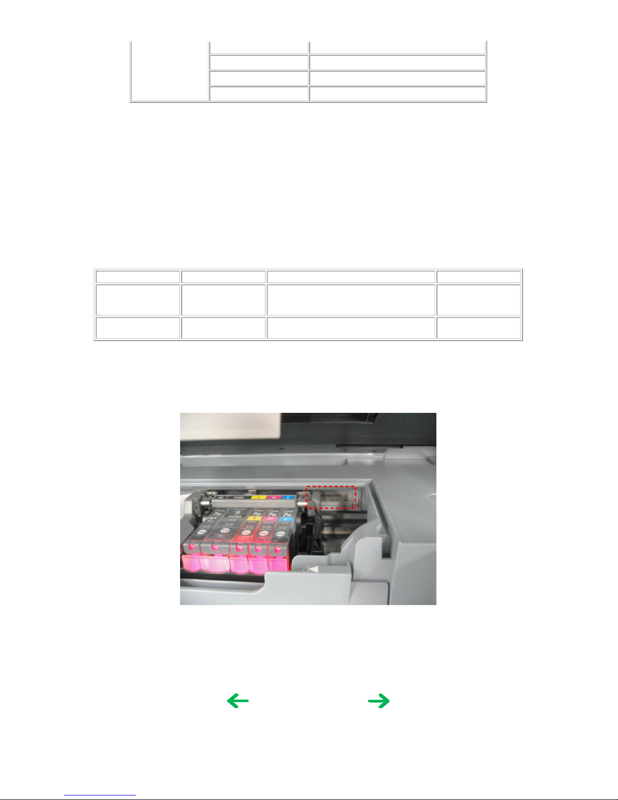
Photo chart
CLI-8BK Approx. 1,100 pages
CLI-8C Approx. 280 pages
CLI-8M Approx. 250 pages
CLI-8Y Approx. 390 pages
Black text: When printing the Canon standard pattern (1,500 characters per page) on A4 size plain paper, with the default settings in the
Windows XP driver, using Word 2003.
Color chart: When printing the ISO/JIS-SCID N5 pattern on A4 size plain paper in bordered printing, with the default settings in the Windows
XP driver, using Photoshop 7.0.
Photo chart: When printing the Canon standard pattern on 4" x 6" Photo Paper Plus Glossy in borderless printing, with the default settings in
the Windows XP driver, using Windows XP Photo Printing Wizard.
The print yield in the table above is an average value measured in continuous printing, using the ink tank immediately after it is unsealed, until
the ink is out. Ink yield may vary depending on texts and photos printed, application software, print mode, and type of paper used.
When the machine is turned on and while printing, each ink may be used for protecting the print head and maintaining print quality.
1-4. Special Tools
1-5. Serial Number Location
On the carriage flexible cable holder (visible on the right of the carriage after the machine is turned on, the scanning unit is opened, and the
carriage moves to center).
Name Tool No. Application Remarks
FLOIL KG-107A
QY9-0057-000
To be applied to the sliding portions of the
carriage shaft, lift cam shaft, and machine's
sliding portions (gears).
In common with the
S520.
MOLYKOTE PG-641
CK-0562-000 To be applied to the Open button sliding
portion.
In common with the
i950.
To the table of contents To the top
<Part 1: 1. MAINTENANCE>
1-3

2. LIST OF ERROR DISPLAY / INDICATION
Errors and warnings are displayed by the following ways:
1) Operator call errors are indicated by the Alarm LED lit in orange, and the error and its solution are displayed on the LCD in text and by icon.
2) Warnings during printing from a computer are displayed on the printer driver Status Monitor.
3) Error codes are printed in the "operator call/service call error record" area in EEPROM information print.
Buttons valid when an operator call error occurs:
1) ON/OFF button: To turn the machine off and on again.
2) OK button: To clear and recover from an error. In some operator call errors, the error will automatically be cleared when the ca use of the error
is eliminated, and pressing the OK button may not be necessary.
3) Stop/Reset button: To cancel the job at error occurrence, and to clear the error.
2-1. Operator Call Errors (by Alarm LED Lit in Orange)
Error
Error code
Message on the LCD
Solution
No paper (ASF). [1000]
Auto sheet feeder.
There is no paper. Load paper and press [OK].
Set the paper in the ASF, and press the OK
button.
No CD / DVD tray*1.
[1001]
There is no CD-R tray. Attach the tray and press
[OK].
Set the CD / DVD tray, and press the OK
button.
No paper in the front paper
feed cassette.
[1003]
Cassette.
There is no paper. Load paper and press [OK].
Set the paper in the cassette, and press the OK
button.
No CD or DVD*1.
[1002]
Printable disc is not set. Correctly place a disc in the
CD-R tray and press [OK].
Set a CD or DVD in the CD / DVD tray
(which is ejected at error occurrence), and
inset the CD / DVD tray in the proper
position. Then, press the OK button.
Paper jam.
[1300]
The paper is jammed. Clear the paper and press
[OK].
Remove the jammed paper, and press the OK
button.
Paper jam in the rear guide. [1303]
Paper jam in the under
guide.
[1304]
No ink.
[1600]
Ink has run out. Replace the ink tank and close the
cover. (U041)
Replace the empty ink tank(s), and close the
cover.
Pressing the OK button will clear the error
without ink tank replacement, however, ink
may run out during printing.
Ink tank not installed. [1660]
The following ink tank cannot be recognized.
(Applicable ink tank icon) (U043)
Install the applicable ink tank(s) properly, and
confirm that the LED's of all the ink tanks
light red.
The print head is not
installed, or it is not
properly installed.
[1401]
Print head is not installed. Install the print head.
(U051)
Install the print head properly.
Print head temperature
sensor error
[1403]
The type of print head is incorrect. Install the correct
print head.
Re-set the print head. If the error is not
cleared, the print head may be defective.
Replace the print head.
Faulty EEPROM data of the
print head
[1405]
Inner cover open before
start of printing on paper
(print continuable).
*2
[1841]
Inner cover is open. Close the inner cover and press
[OK].
Close the inner cover, and press the OK
button.
Inner cover open during
printing on paper (print
NOT continuable).
*2
[1846]
Close the inner cover, and press the OK
button to clear the error. The paper being
printed at error occurrence will be ejected
without printing the remaining data for the
ejected paper, then printing will resume from
the next page.
Inner cover open before
start of printing on paper
(print continuable).
*1
[1851]
Close the inner cover, and press the OK
button.
Inner cover open during
printing on paper (print
[1856]
Close the inner cover, and press the OK
button to clear the error. The paper being
1-4

*1: Only for models supporting CD / DVD printing
*2: Onl
y
for models not supporting CD / DVD printin
g
NOT continuable).
*1
printed at error occurrence will be ejected
without printing the remaining data for the
ejected paper, then printing will resume from
the next page.
Inner cover closed before
start of CD / DVD printing
(print continuable).
*1
[1850]
Open the inner cover, place the CD-R tray and press
[OK].
Open the inner cover which functions as the
CD / DVD tray feeder, set the CD / DVD tray
in the feeder, and press the OK button.
Inner cover closed during
CD / DVD printing (print
NOT continuable).
*1
[1855]
Open the inner cover, and press the OK
button to clear the error. The CD or DVD
being printed at error occurrence will be
ejected without printing the remaining data
for the ejected CD or DVD, then the next
print job will be done.
Multiple ink tanks of the
same color installed.
[1681]
More than one ink tank of the following color is
installed. (U075)
Replace the wrong ink tank(s) with the
correct one(s).
Ink tank in a wrong
position.
[1680] Some ink tanks are not installed in place. (U072)
Install the ink tank(s) in the correct position.
Warning: The waste ink
absorber becomes almost
full.
[1700]
The waste ink absorber is almost full. Press [OK] to
continue but early replacement recommended. <See
manual>
Press the OK button.
The service call error, indicating the waste
ink absorber is full, is likely to occur soon.
The connected digital
camera or digital video
camera does not support
Camera Direct Printing.
[2001]
Incompatible device detected. Remove the device.
Remove the cable between the camera and
the machine.
Automatic duplex printing
cannot be performed.
[1310]
This paper is not compatible with duplex printing.
Remove the paper and press [OK].
Press the OK button to eject the paper being
used at error occurrence. Printing will resume
from on the front side of the next page. Data
which was to be printed on the back side of
paper at error occurrence is skipped (not
printed).
Failed in automatic print
head alignment.
[2500]
Auto head align has failed. Press [OK] and repeat
operation. <See manual>
Press the OK button.
- If paper is being fed at error occurrence, the
error is indicated after the paper is ejected.
- If the error occurs, the print head alignment
values are not changed.
- After exit from the error by the OK button,
the automatic print head alignment will not
be re-done.
The error will occur when the print head
alignment pattern is not printed due to no ink
or non-ejection of ink.
The remaining ink amount
unknown.
[1683]
(Applicable ink tank icon)
The remaining level of the following ink cannot be
correctly detected.
An ink tank which has once been empty is
installed. Replace the applicable ink tank with
a new one.
Printing with a once-empty or refilled ink
tank can damage the print head.
If printing is continued without replacing the
refilled ink tank, press the Stop/Reset button
for 5 sec. or longer to record the use of a
refilled ink tank.
Note:
After the above operation, the function to
detect the remaining ink amount is disabled.
Ink tank not recognized. [1684]
(Applicable ink tank icon)
The following ink tank cannot be recognized. (U140)
A non-supported ink tank is installed (the ink
tank LED is turned off). Install the supported
ink tanks.
Ink tank not recognized.
[1410 to 1419]
[1682]
(Applicable ink tank icon)
The following ink tank cannot be recognized. (U150)
An error occurred in an ink tank (the ink tank
LED is turned off). Replace the ink tank(s).
Scanning unit (printer
cover) open.
[1200] Cover is open. Close the cover.
Close the scanning unit (printer cover).
Scanner lock switch locked. [5020]
Release the scanner lock switch and turn the power
off and back on.
Turn the machine off, unlock the scanner lock
switch, then turn the machine on again.
1-5
2-2. Service Call Errors (by Cyclic Blinking in Orange (Alarm LED) and Green (COPY button), or Alarm LED Lit
in Orange)
Service call errors are indicated by the number of cycles the Alarm LED and COPY button blink, and the corresponding error code is displayed
on the LCD
.
Cycles of blinking in
orange (Alarm LED)
and green (COPY
button)
Error
Error
code
Conditions
Solution
(Replacement of listed parts, which are
likely to be faulty)
2 times
Carriage error [5100] An error occurred in the carriage encoder signal. - Carriage unit
- Timing slit film
- Logic board
- Carriage motor
3 times
Line feed error [6000] An error occurred in the LF encoder signal. - Timing sensor unit
- Timing slit disk film
- Feed roller
- Platen unit
- Logic board
- Paper feed motor
4 times
Purge cam
sensor error
[5C00] An error occurred in the purge unit. - Purge unit
- Logic board
5 times
ASF (cam)
sensor error
[5700]
This error takes place when feeding paper from the
ASF after an error occurred in the ASF cam sensor.
- Sheet feed unit
6 times Internal
temperature
error
[5400] The internal temperature is not proper.
- Logic board
- Carriage unit
7 times Waste ink
absorber full
[5B00] The waste ink absorber is full.
- Ink absorber kit
8 times
Print head
temperature rise
error
[5200] The print head temperature exceeded the specified
value.
- Print head
- Logic board
9 times
EEPROM error [6800] A problem occurred in writing to the EEPROM. - Logic board
11 times
Carriage lift
mechanism
error
[5110] The carriage did not move up or down properly. - PR lift shaft
- Sheet feed unit
- Logic board
- Carriage lift sensor unit
12 times
AP position
error
[6A00] An error occurred in the AP motor during purging
operation.
- Sheet feed unit
- Logic board
- Purge unit
13 times
Paper feed
position error
[6B00] An error occurred in the paper feed motor.
- Sheet feed unit
- Logic board
14 times
Paper feed cam
sensor error
[6B10] An error occurred in the paper feed cam sensor during
paper feeding from the front paper feed cassette.
This error is also indicated when the waste ink counter
is 60% or more, and a paper jam occurs in the under
guide.
- Sheet feed unit
- Logic board
15 times
USB Host
VBUS
overcurrent
[9000] The USB Host VBUS is overloaded. - Logic board
16 times
Valve sensor
error
[6C00] An error occurred in the valve sensor during cleaning.
- Logic board
- Purge unit
17 times
Motor driver
error
[6D00] The AD conversion value indicating the motor driver
temperature is not proper.
- Logic board
19 times Ink tank
position sensor
error
[6502] None of the ink tank position is detected.
- Platen unit
- Logic board
20 times Other hardware
error
[6500] The PCI bus error is detected by the ASIC. - Logic board
22 times Scanner error [5010] The scanner unit cannot detect the home position, or
the scanner unit warming-up is not done properly at
power-on.
On the LCD, "Scanner is not operating correctly." is
displayed.
- Scanner unit
Continuous alternate ROM error
[6100] The check sum value is incorrect in the ROM check at - Logic board
1-6
Note: Before replacement of the logic board ass'y, check the waste ink amount (by service test print or EEPROM information print). If the
waste ink amount is 7% or more, also replace the ink absorber kit (QY5-0153) when replacing the logic board ass'y. [See Section 3-3.
Adjustment / Settings, (6) Service mode, for details.]
2-3. Fax Errors
For errors other than those listed below, please refer to the "G3 / G4 Facsimile Error Code List (Rev. 2)."
(1) User error codes
(2) Service error codes
blinking
hard-power-on.
Alarm LED lit RAM error [6300] The RAM error occurred in the RAM check at hard-
power-on.
- Logic board
Error code TX / RX Meaning
#001
TX Document jam
#003
TX / RX Document is too long, or page time-over
#005
TX / RX Initial identification (T0 / T1) time-over
#009
RX Recording paper jam, or no recording paper
#012
TX No recording paper at the receiving machine
#017
TX Redial time-over, but no DT detected
#018
TX Auto dialing transmission error, or redial time-over
#022
TX Call failed (no dial registration)
#037
RX Memory overflow at reception of an image
#085
TX No color fax function supported in the receiving machine
#099
TX / RX Transmission terminated mid-way by pressing the Stop/Reset button
#995
TX / RX During TX (sending): Memory transmission reservation cancelled
During RX (receiving): Image data received in the memory cleared
Error code TX / RX Meaning
##100
TX Re-transmission of the procedure signal has been attempted the specified number of times, but failed.
##101
TX / RX Sender's modem speed does not match the receiving machine.
##102
TX Fallback is not available.
##103
RX EOL has not been detected for 5 seconds (or 15 seconds in CBT).
##104
TX RTN or PIN has been received.
##106
RX The procedure signal has been expected for 6 seconds, but not received.
##107
RX Fallback is not available at the sending machine.
##109
TX After DCS transmission, a signal other than DIS, DTC, FTT, CFR, or CRP has been received, and re-transmission of the
procedure signal has been attempted the specified number of times but failed.
##111
TX / RX Memory error
##114
RX RTN has been received.
##200
RX A carrier has not been detected for 5 seconds during image reception.
##201
TX / RX DCN has been received in a method other than the binary procedure.
##204
TX DTC has been received even when there is no sending data.
##220
TX / RX System error (main program hang-up)
##224
TX / RX An error has occurred in the procedure signal in G3 transmission.
##226
TX / RX The stack pointer has shifted from the RAM area.
##229
RX The recording area has been locked for 1 minute.
##232
TX The encoder control unit has malfunctioned.
##237
RX The decoder control unit has malfunctioned.
##238
RX The print control unit has malfunctioned.
##261
TX / RX A system error has occurred between the modem and the system control board.
1-7
##280
TX Re-transmission of the procedure signal has been attempted the specified number of times, but failed.
##281
TX Re-transmission of the procedure signal has been attempted the specified number of times, but failed.
##282
TX Re-transmission of the procedure signal has been attempted the specified number of times, but failed.
##283
TX Re-transmission of the procedure signal has been attempted the specified number of times, but failed.
##284
TX After TCF transmission, DCN has been received.
##285
TX After EOP transmission, DCN has been received.
##286
TX After EOM transmission, DCN has been received.
##287
TX After MPS transmission, DCN has been received.
##288
TX After EOP transmission, a signal other than PIN, PIP, MCF, RTP, RTN has been received.
##289
TX After EOM transmission, a signal other than PIN, PIP, MCF, RTP, RTN has been received.
##290
TX After MPS transmission, a signal other than PIN, PIP, MCF, RTP, RTN has been received.
##670
TX In V.8 late start, the DIS V.8 ability from the receiving machine was detected, and CI was sent in response; however, the
procedure failed, causing T1 time-over.
##671
RX In V.8 call reception, the procedure fails to proceed to phase 2 after CM detection, causing T1 time-over.
##672
TX In V.34 transmission, the procedure fails to proceed from phase 2 to phase 3 or later, causing T1 time-over
##673
RX In V.34 reception, the procedure fails to proceed from phase 2 to phase 3 or later, causing T1 time-over
##674
TX In V.34 transmission, the procedure fails to proceed from phase 3 or 4 to the control channel or later, causing T1 time-
over
##675
RX In V.34 reception, the procedure fails to proceed from phase 3 or 4 to the control channel or further, causing T1 time-over
##750
TX After transmitting PPS-NULL in ECM transmission, no significant signal has been received, and re-transmission of the
procedure signal has been attempted the number of specified times but failed.
##752
TX After transmitting PPS-NULL in ECM transmission, DCN has been received.
##753
TX After transmitting PPS-NULL in ECM transmission, re-transmission of the procedure signal has been attempted the
number of specified times but failed, or T5 time-over (60 sec.) has occurred.
##754
TX After transmitting PPS-NULL in ECM transmission, re-transmission of the procedure signal has been attempted the
number of specified times but failed.
##755
TX After transmitting PPS-MPS in ECM transmission, no significant signal has been received, and re-transmission of the
procedure signal has been attempted the number of specified times but failed.
##757
TX After transmitting PPS-MPS in ECM transmission, DCN has been received.
##758
TX After transmitting PPS-MPS in ECM transmission, re-transmission of the procedure signal has been attempted the
number of specified times but failed, or T5 time-over (60 sec.) has occurred.
##759
TX After transmitting PPS-MPS in ECM transmission, re-transmission of the procedure signal has been attempted the
number of specified times but failed.
##760
TX After transmitting PPS-EOM in ECM transmission, no significant signal has been received, and re-transmission of the
procedure signal has been attempted the number of specified times but failed.
##762
TX After transmitting PPS-EOM in ECM transmission, DCN has been received.
##763
TX After transmitting PPS-EOM in ECM transmission, re-transmission of the procedure signal has been attempted the
number of specified times but failed, or T5 time-over (60 sec.) has occurred.
##764
TX After transmitting PPS-EOM in ECM transmission, re-transmission of the procedure signal has been attempted the
number of specified times but failed.
##765
TX After transmitting PPS-EOP in ECM transmission, no significant signal has been received, and r e-transmission of the
procedure signal has been attempted the number of specified times but failed.
##767
TX After transmitting PPS-EOP in ECM transmission, DCN has been received.
##768
TX After transmitting PPS-EOP in ECM transmission, re-transmission of the procedure signal has been attempted the number
of specified times but failed, or T5 time-over (60 sec.) has occurred.
##769
TX After transmitting PPS-EOP in ECM transmission, re-transmission of the procedure signal has been attempted the number
of specified times but failed.
##770
TX After transmitting EOR-NULL in ECM transmission, no significant signal has been received, and re-transmission of the
procedure signal has been attempted the number of specified times but failed.
##772
TX After transmitting EOR-NULL in ECM transmission, DCN has been received.
##773
TX After transmitting EOR-NULL in ECM transmission, re-transmission of the procedure signal has been attempted the
number of specified times but failed, or T5 time-over (60 sec.) has occurred.
##774
TX After transmitting EOR-NULL in ECM transmission, ERR has been received.
##775
TX After transmitting EOR-MPS in ECM transmission, no significant signal has been received, and re-transmission of the
procedure signal has been attempted the number of specified times but failed.
##777
TX After transmitting EOR-MPS in ECM transmission, DCN has been received.
##778
TX After transmitting EOR-MPS in ECM transmission, re-transmission of the procedure signal has been attempted the
1-8
2-4. Other Error Messages
number of specified times but failed, or T5 time-over (60 sec.) has occurred.
##779
TX After transmitting EOR-MPS in ECM transmission, ERR has been received.
##780
TX After transmitting EOR-EOM in ECM transmission, no significant signal has been received, and re-transmission of the
procedure signal has been attempted the number of specified times but failed.
##782
TX After transmitting EOR-EOM in ECM transmission, DCN has been received.
##783
TX After transmitting EOR-EOM in ECM transmission, re-transmission of the procedure signal has been attempted the
number of specified times but failed, or T5 time-over (60 sec.) has occurred.
##784
TX After transmitting EOR-EOM in ECM transmission, ERR has been received.
##785
TX After transmitting EOR-EOP in ECM transmission, no significant signal has been received, and re-transmission of the
procedure signal has been attempted the number of specified times but failed.
##787
TX After transmitting EOR-EOP in ECM transmission, DCN has been received.
##788
TX After transmitting EOR-EOP in ECM transmission, re-transmission of the procedure signal has been attempted the
number of specified times but failed, or T5 time-over (60 sec.) has occurred.
##789
TX After transmitting EOR-EOP in ECM transmission, ERR has been received.
##790
RX After receiving EOR-EOP in ECM reception, ERR has been transmitted.
##791
TX / RX During the ECM mode procedure, a signal other than a significant one has been received.
##792
RX In ECM reception, PPS-NULL between partial pages has not been detected.
##793
RX During high-speed signal reception in ECM, no effective frame has been detected, and a time-over has occurred.
Message on the LCD Cause Solution
The selected paper cannot be fed from
cassette. Change the paper source.
The paper type being used is not supported for
paper feeding from the cassette.
Change the paper source to the ASF.
Cannot specify the followings together.
Change one of the settings.
Settings made conflict each other. The error message is displayed for a while, then
the LCD automatically returns to the display
before the error occurrence.
Device memory is full. Cannot continue
process. Reduce the number of photos to
print.
The memory is not sufficient to do the print job.
Reduce the amount of data to be printed, or print
from a computer.
Failed to scan. Either document cannot be
scanned or is not placed on the platen
glass.
The machine failed in scanning the document for
Fit-to-page copy, or photos or films were not
recognized in pre-scanning.
Press the OK button to clear the error. The LCD
automatically returns to the display before the
error occurrence.
Press <>.
(<>: Color button icon)
The Black button was pressed, but it is invalid.
A temporary error. Press the Color button to
continue the operation.
Press <>.
(<>: Black button icon)
The Color button was pressed, but it is invalid.
A temporary error. Press the Black button to
continue the operation.
There are no photos in memory card.
Supported image files are not in the memory card.
The error message is displayed for a while, then
disappears.
The value exceeds the number of copies
you can print.
During selecting images or specifying the number
of copies, the total print quantity exceeds the
prescribed value of 999.
After the error message is displayed for a while,
the last operation before the error is cancelled, and
the total print quantity returns to the value before
the error.
Memory card is not set. Insert the card
after checking the direction.
No memory card is inserted in the slot. Set a memory card.
DPOF information is not saved in the
memory card.
DPOF print was selected in the menu, but no
DPOF files are contained in the memory card.
The error message is displayed for a while, then
the LCD automatically returns to the display
before the error occurrence.
The number of copies to print is not set.
Input the number of copies.
Multi-photo print was attempted without
specifying the print quantity (with the print
quantity left "0" (zero)).
The error message is displayed for a while, then
disappears. Specify the print quantity.
This layout is available only for A4 or
8.5"x11"(LTR).
In Layout print, "Mixed 1, 2, or 3" which is
available only with A4 or LTR size paper is
selected, but the paper size is not set to A4 or
LTR.
The error message is displayed for a while, then
the LCD automatically returns to the display
before the error occurrence.
Settings cannot be changed when printing
stickers.
With Sticker print selected, the Settings button
was pressed.
The error message is displayed for a while, then
the LCD automatically returns to the display
before the error occurrence.
1-9
2-5. Warnings
Change the setting after removing the card. With a memory card inserted in the slot, change of
the Read/Write attribute was attempted.
The error message is displayed for a while, then
the LCD automatically returns to the display
before the error occurrence.
The card is currently write-enabled. Set to
read-only mode before performing
operation.
With the memory card set to the Read/write mode,
Card Direct printing operation was attempted from
the menu.
The error message is displayed for a while, then
the LCD automatically returns to the display
before the error occurrence.
The paper size is not correct. Check the
page size you have set.
Non-supported size of paper for PictBridge
Camera Direct printing is selected.
Cancel printing on the digital camera.
Failed to scan Photo Index Sheet. Check
the orientation, position and marking. <See
manual>
The machine failed in scanning the Photo Index
Sheet.
Press the OK button to clear the error. The LCD
automatically returns to the display before the
error occurrence.
Photo scan error. Photo size is too large.
Leave at least 10mm between photos.
In cropping multiple photos at the same time,
since the space between the photos were not
sufficient, the photos were considered as a single
JPEG file, and the file became too large.
Press the OK button to clear the error. The LCD
automatically returns to the display before the
error occurrence.
Warning Message on the LCD Solution
Low ink The following ink is low. Continue?
(Icon of each ink tank)
Yes No
- Select
Yes
, and press the OK button.
=> Printing starts, and it is indicated on the LCD.
- Select No, and press the OK button.
=> Printing is cancelled, and the LCD returns to the
display immediately before printing was
attempted.
In Camera Direct Printing, only "Yes" can be selected.
Print head temperature rise If the print head temperature does not fall, the error code
"5200" is displayed, indicating the print head temperature
rise error.
When the print head temperature falls, the error is
automatically cleared.
Note:
If the print head temperature exceeds the specified limit
when the scanning unit (printer cover) is opened, the
carriage does not move to the ink tank replacement
position.
Protection of excess rise of
the print head temperature
If the print head temperature does not fall, the error code
"5200" is displayed, indicating the print head temperature
rise error.
If the print head temperature exceeds the specified limit,
an intermission is inserted during printing.
Restrictions on paper
The current paper cannot be set. Change the size and type.
Re-select the supported paper type and size.
Recommendation of the
print head alignment (only
on arrival of the machine)
Head alignment required. Load paper and press [OK].
Yes No
- Select
Yes
, and press the OK button.
=> Automatic print head alignment is performed.
- Select No, and press the OK button.
=> The procedures on arrival of the machine are
finished.
USB cable not connected
Connect USB cable and turn on the PC.
Connect the USB cable.
Cancellation of trimming Reset trimming effect?
Yes No
With a trimmed image present, when printing on a DVD
or CD is attempted, the message is displayed.
- Select
Yes
, and press the OK button.
=> The trimming is cancelled, and printing on a DVD
or CD can be performed.
- Select No, and press the OK button.
=> The LCD returns to the display immediately before
the message was displayed.
Cancellation of image select
information
Reset the selected photo information?
Yes No
When one or more images are selected in Multi-photo
print or Layout print, and if a user tries to display the
menu or sub-menu, the message is displayed.
- Select
Yes
, and press the OK button.
=> The image selection is cancelled, and the menu or
sub-menu is displayed.
- Select No, and press the OK button.
=> The LCD returns to the display immediately before
the message was displayed.
1-10

2-6. Troubleshooting by Symptom
Symptom Solution
Faulty operation The power does not turn on.
The power turns off immediately after poweron.
- Confirm the connection of
- the power cord, and
- between the logic board and the power supply unit.
- Replace the
- power supply unit, or
- logic board.
A strange noise occurs.
- Remove foreign material.
- Attach a removed part if any.
- Check the operation of the moving parts (such as purge unit,
carriage unit, and paper feeding mechanism)
- Replace a faulty part, if any.
Nothing is displayed on the LCD. - Confirm the connection between the operation panel, the scanning
unit, and the logic board.
- Replace the
- LCD, or
- logic board.
A portion of the LCD is not displayed. - Perform the button and LCD test in the service mode, and confirm
that the LCD is displayed without any segments missing.
- Confirm the connection between the operation panel, the scanning
unit, and the logic board.
- Replace the
- LCD, or
- logic board.
Paper feed problems (multi-feeding, skewed
feeding, no feeding).
- Examine the inside to confirm that no parts are damaged, and the
rollers are clean.
- Remove foreign material.
- Adjust the paper guide properly.
- Confirm the connection of each harness and the logic board.
- Replace the
- sheet feeder unit,
- cassette, or
- logic board.
Carriage movement problems (contact to other
parts, strange noise).
- Confirm that the carriage timing slit strip film is free from damage
or grease.
- Clean the carriage timing slit strip film (with ethanol and lint-free
paper).
- Replace the
- carriage timing slit strip film, or
- carriage unit.
Faulty scanning (no scanning, strange noise). - Confirm the connection between the scanning unit and the logic
board.
- Replace the
- scanning unit, or
- logic board.
No paper feeding from the ADF (no operation
of the ADF motor).
- Confirm the connection
- between the ADF motor and the ADF PWB, and
- between the ADF PWB and the logic board.
- Replace the
- document feed unit, or
- logic board.
No sound from the speaker. - Confirm the connection between the speaker and the logic board.
- Replace the
- speaker, or
- logic board.
Unsatisfactory print quality No printing, or no color ejected. - Replace the
- ink tank,
- print head
*1
, or
- logic board.
- Remove foreign material from the purge unit caps, if any.
- Replace the purge unit.
Printing is faint, or white lines appear on
printouts even after print head cleaning.
Line(s) not included in the print data appears
on printouts.
- Remove and re-install the print head.
- Replace the
- ink tank,
- print head
*1
,
- purge unit, or
- logic board.
Paper gets smeared. - Feed several sheets of paper.
1-11

*1: Replace the print head only after the print head deep cleaning is performed 2 times, and when the problem persists.
- Perform bottom plate cleaning.
- Clean the paper path with cotton swab or cloth.
- Clean the ASF sub-rollers.
A part of a line is missing on printouts. - Replace the
- ink tank, or
- print head
*1
.
Color hue is incorrect. - Replace the
- ink tank, or
- print head
*1
.
- Perform print head alignment.
Printing is incorrect. Replace the logic board.
No ejection of black ink. - Replace the
- ink tank, or
- print head
*1
.
- Remove foreign material from the purge unit caps, if any.
- Replace the purge unit.
Graphic or text is enlarged on printouts.
When enlarged in the carriage movement direction:
- Clean grease or oil off the timing slit strip film
- Replace the
- timing slit strip film,
- carriage unit, or
- logic board.
When enlarged in the paper feed direction:
- Clean grease or oil off the timing slit disk film
- Replace the
- timing slit disk film,
- timing sensor unit, or
- logic board.
Faulty scanning
No scanning. - Confirm the connection between the scanning unit and the logic
board.
- Replace the
- scanning unit, or
- logic board.
Streaks or smears on the scanned image. - Clean the platen glass and the ADF.
- Confirm the connection between the scanning unit and the logic
board.
- Replace the
- scanning unit,
- logic board, or
- sponge sheet.
No paper feeding from the ADF (no operation
of the ADF motor).
- Confirm the connection
- between the ADF motor and the ADF PWB, and
- between the ADF PWB and the logic board.
- Replace the
- document feed unit, or
- logic board.
Document slipping over the roller (copied
image enlarged), or document not separated.
- Clean the friction tab, document feed roller, and separation roller.
- Replace the document feed unit.
1-12
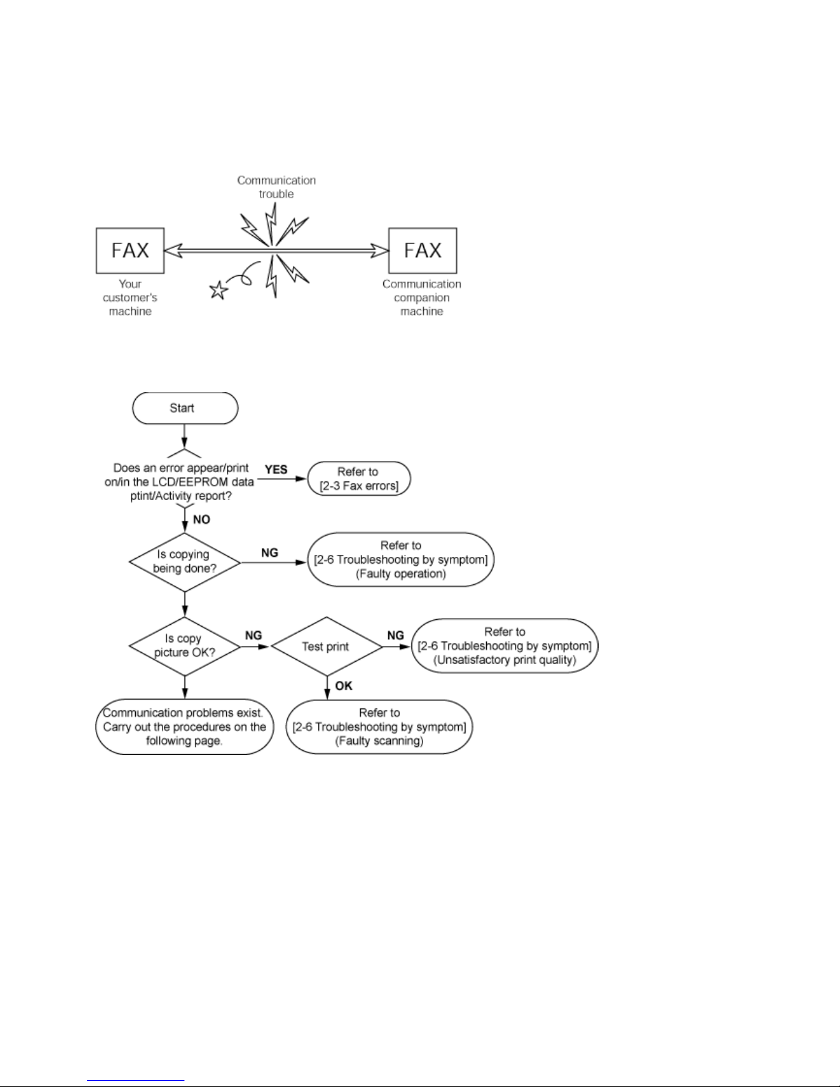
2-7. Fax Communication Troubleshooting
(1) Identification of a trouble
A fax machine transmits image data to a receiver through a telephone line. A trouble in any of the transmitter, receiver, and telephone line can
prevent the machine from transmitting image data properly.
For the best solution to your fax trouble, follow the flowchart below to determine whether it is a communication trouble or not.
1-13

(2) Handling of a communication trouble
Follow the procedure below to handle communication troubles.
1) Investigate the condition in which the trouble occurred.
a. User operation at trouble occurrence
- Number of sheets of the document
- Transmission mode
- Timing when the error occurred (e.g. before or after transmission)
- Other settings (e. g. such as automatic dialing)
b. Sample print of a faulty fax reception
c. Message on the LCD at trouble occurrence
d. Activity report at trouble occurrence
e. User name, telephone number, fax number, and model name
f. The other party's user name, telephone number, fax number, model name, and service engineer name
g. Frequency and error type of the trouble
h. The other party's fax condition
- Number of sheets transmitted
- Communication mode (automatic or manual)
- Whether an error occurred or not
- Reception condition, etc.
Memo: The number of sheets / times of communication and error code can be confirmed in EEPROM information print.
2) Conduct the communication test, by following the flowchart below.
- Perform the operations using the actual line several times each, and record the phenomenon.
- If a communication trouble occurs between a Canon machine and a non-Canon machine, follow the flowchart for the communication test
with a non-Canon machine.
3) Handle the problem based on the investigation and test results.
Memo: If a trouble occurs in communication with a non-Canon machine, and if a Canon machine operates properly without any problems,
it is recommended to let the user understand that the non-Canon machine needs to be examined accordingly. Since the cause of the
trouble may exists in communication ability of the machine, contact a relevant service contact point of a non-Canon machine. In
such a case, the information obtained in step 1) will be a help for quick solution to the problem.
1-14
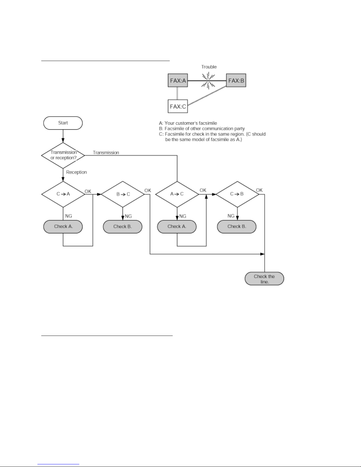
<Communication test between Canon machines>
Conduct the 3-point communication shown in the diagram.
Test flowchart of communication test between Canon machines:
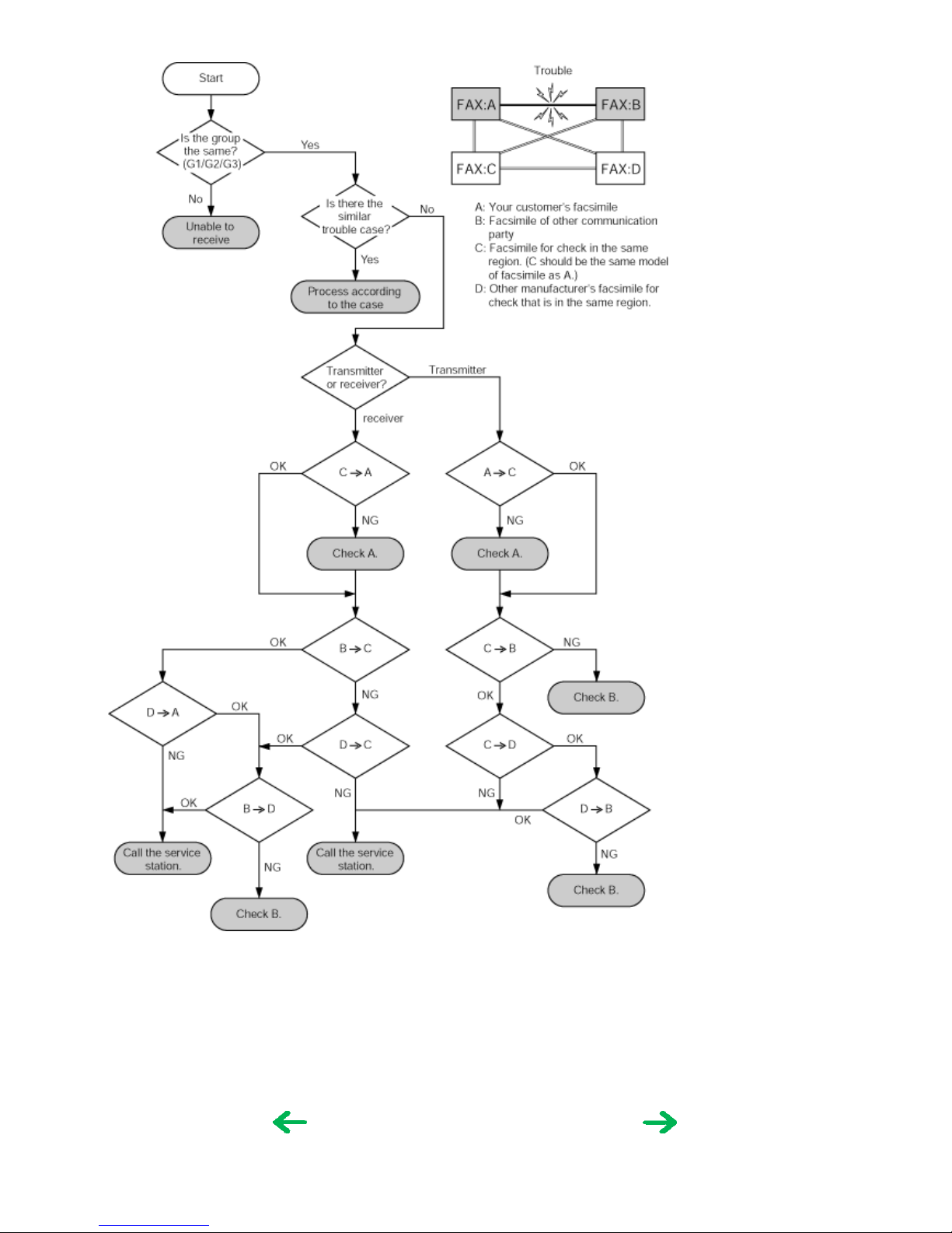
<Communication test with a non-Canon machine>
Ask a non-Canon machine user to request servicing, and conduct the 4-point communication test shown below.
Test flowchart of communication test with a non
-Canon machine:
1-15

3. REPAIR
3-1. Notes on Service Part Replacement (and Disassembling / Reassembling)
Service part
Notes on replacement
*1
Adjustment / settings Operation check
Logic board ass'y
QM2-3659
- Before removal of the logic board
ass'y, remove the power cord, and
allow for approx. 1 minute (for
discharge of capacitor's accumulated
charges), to prevent damages to the
logic board ass'y.
- Before replacement, check the waste
ink amount (by service test print or
EEPROM information print).
[See 3-4. Verification Items, (1)
Service test print, or (2) EEPROM
information print, for details.]
After replacement:
1. Initialize the EEPROM.
2. Set the destination in the
EEPROM.
3. Reset the waste ink counter.
4. Correct the CD / DVD and
automatic print head alignment
sensors.
5. Check the ink system function.
6. Adjust the line feeding.
[See 3-3. Adjustment / Settings, (6)
Service mode, for details of 1 to 6]
7. Perform the print head alignment in
the user mode.
- EEPROM information print
- Service test print
- Printing via USB connection
- Copy
- Direct printing from a digital
camera
- Fax transmission and reception
Absorber kit
QY5-0153
After replacement:
1. Reset the waste ink counter.
[See 3.3. Adjustment / Settings, (6)
Service mode.]
- Service test print
- EEPROM information print
Carriage unit
QM2-3025
At replacement:
1. Apply grease to the sliding
portions.
[See 3-3. Adjustment / Settings,
(2) Grease application.]
After replacement:
1. Correct the CD / DVD and
automatic print head alignment
sensors.
[See 3.3. Adjustment / Settings,
(6) Service mode.]
2. Check the ink system function.
[See 3.3. Adjustment / Settings,
(6) Service mode.]
3. Perform the print head alignment in
the user mode.
- Service test print (Confirm CD /
DVD and automatic print head
alignment sensor correction, and
ink system function.)
Paper feed motor
QK1-1502
- The red screws securing the paper
feed motor are allowed to be
loosened. (DO NOT loosen any
other red screws.)
At replacement:
1. Adjust the paper feed motor.
[See 3-3. Adjustment / Settings, (1)
Paper feed motor adjustment.]
Platen unit
QM2-3565
After replacement:
1. Check the ink system function.
[See 3.3. Adjustment / Settings, (6)
Service mode.]
- Service test print
PR lift shaft ass'y
QL2-0936
At replacement:
1. Apply grease to the sliding
portions.
[See 3.3. Adjustment / Settings, (2)
Grease application.]
- Service test print
Carriage lift base unit
QM2-2232
At replacement:
1. Apply grease to the sliding
portions.
[See 3.3. Adjustment / Settings, (2)
Grease application.]
Timing slit strip film
QC1-6526
- Upon contact with the film, wipe the
film with ethanol.
- Confirm no grease is on the film.
(Wipe off any grease thoroughly
with ethanol.)
- Do not bend the film
After replacement:
1. Perform the print head alignment in
the user mode.
- Service test print
Timing slit disk film
QC1-6229
Print head
QY6-0061
After replacement:
1. Perform the print head alignment in
the user mode.
- Service test print
1-17
To the table of contents To the top
<Part 1: 2. LIST OF ERROR DISPLAY / INDICATION>
1-16

*1: General notes:
- Make sure that the flexible cables and wires in the harness are in the proper position and connected correctly.
[See 3-2. Special Notes on Repair Servicing, for details.]
- Do not drop the ferrite core, which may cause damage.
- Protect electrical parts from damage due to static electricity.
- Before removing a unit, after removing the power cord, allow the machine to sit for approx. 1 minute (for capacitor discharging to
protect the logic board ass'y from damages).
- Do not touch the timing slit strip film and timing slit disk film. No grease or abrasion is allowed.
- Protect the units from soiled with ink.
- Protect the housing from scratches.
- Exercise caution with the red screws, as follows:
i. The red screws of the paper feed motor may be loosened only at replacement of the paper feed motor unit (DO NOT loosen them
in other cases).
ii. DO NOT loosen the red screws on both sides of the main chassis, securing the carriage shaft positioning (they are not adjustable
in servicing)
To the table of contents To the top
<Part 1: 3. REPAIR; 3-1. Notes on Service Part Replacement>
1-18
3-2. Special Notes on Repair Servicing
*****************************************************************************
If there is a power failure or if you disconnect the power cord, the date/time settings as well as
all documents stored in memory will be lost. User data and speed dialing settings are retained.
*****************************************************************************
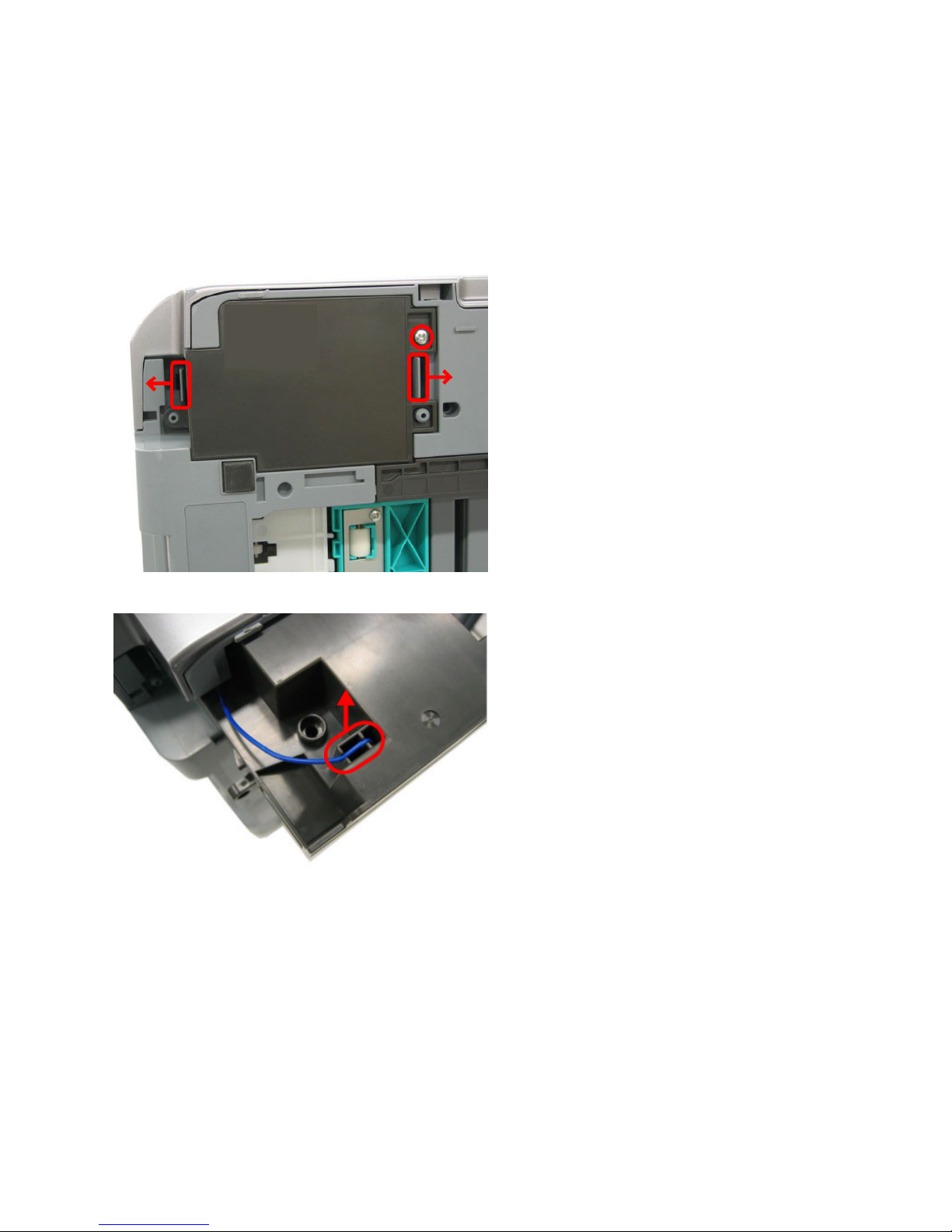
(1) Power supply unit removal / reassembly
Removal:
- Remove the screw.
- While releasing the 2 hooks outwards, slide the power supply unit toward you.
- Manually pull the arrester ground wire off the unit.
1-19
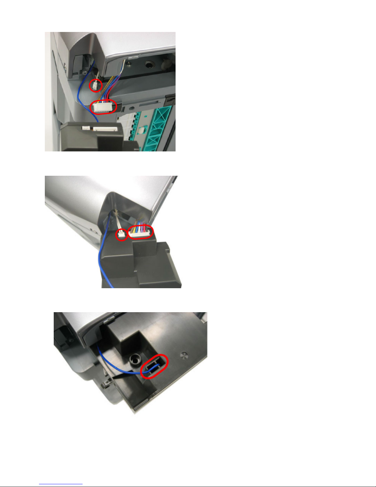
- Disconnect the 2 connectors.
Reassembly:
- Connect the 2 connectors.
- Connect the arrester ground wire.
- Align the ground wire in the groove at 2 locations.
1-20
 Loading...