

Canon LBP351 Series, LP352 Series Service Manual

LBP351/352 Series
Service Manual
Revision 4.0

1x
1x
Introduction
Introduction
Important Notices
Application
This manual has been issued by Canon Inc. for qualified persons to learn technical theory, installation, maintenance, and repair
of products.
This manual covers all localities where the products are sold. For this reason, there may be information in this manual that does
not apply to your locality.
Corrections
This manual may contain technical inaccuracies or typographical errors due to improvements or changes in products.
When changes occur in applicable products or in the contents of this manual, Canon will release technical information as the
need arises. In the event of major changes in the contents of this manual over a long or short period, Canon will issue a new
edition of this manual.
The following paragraph does not apply to any countries where such provisions are inconsistent with local law.
Trademarks
The product names and company names used in this manual are the registered trademarks of the individual companies.
Copyright
The copyright of this document belongs to Canon Inc. This document may not be copied, reproduced or translated into another
language, in whole or in part, without the prior consent of Canon Inc.
Copyright CANON INC. 2017
Caution
Use of this manual should be strictly supervised to avoid disclosure of confidential information.
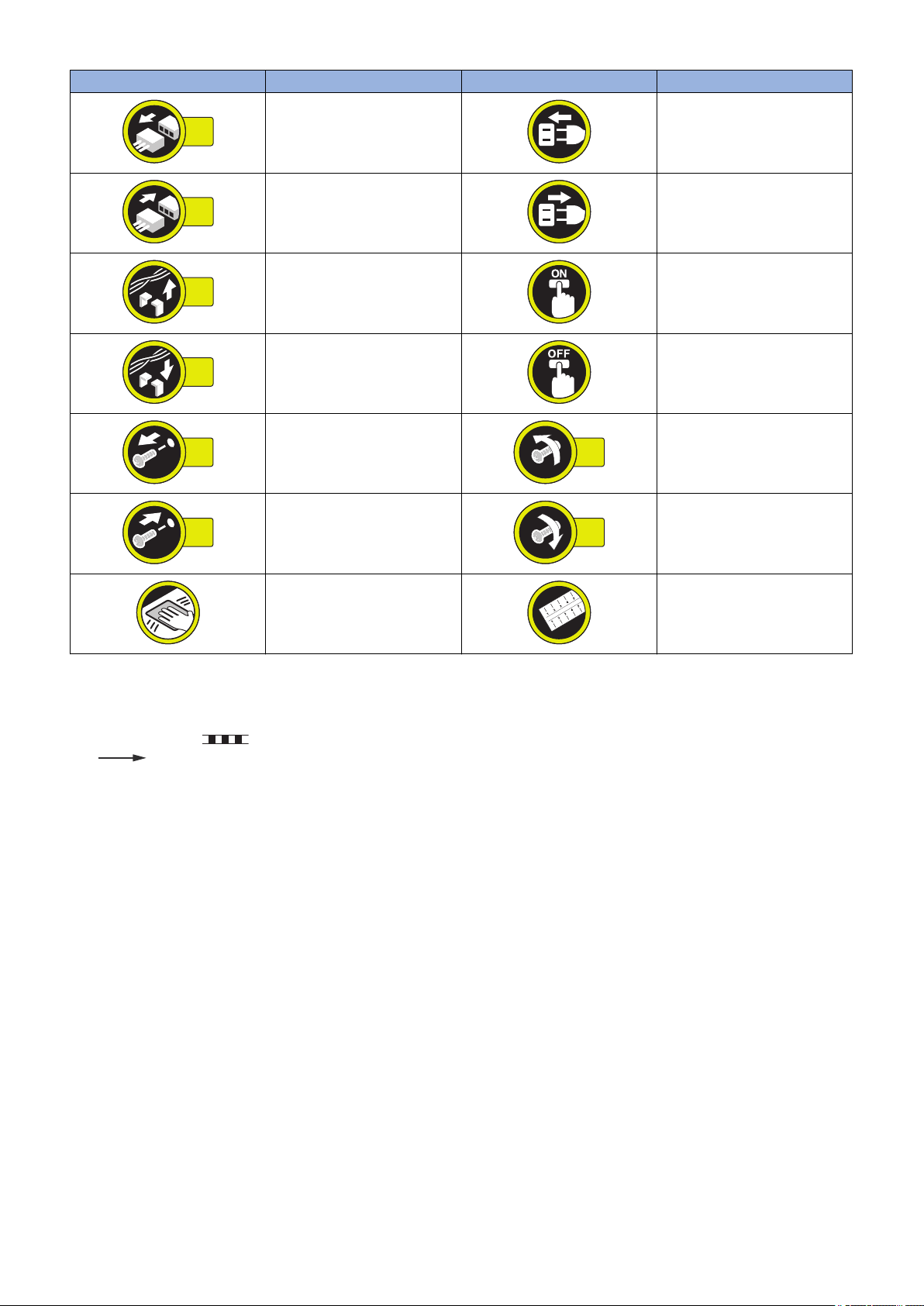
Explanation of Symbols
The following symbols are used throughout this Service Manual.
Symbols Explanation Symbols Explanation
Check.
Remove the claw.
Check visually.
Check a sound. Push the part.
Insert the claw.
1x
1x
1x
1x
1x
1x
1x
1x
Introduction
Symbols Explanation Symbols Explanation
Disconnect the connector. Connect the power cable.
Connect the connector. Disconnect the power cable.
Remove the cable/wire from the
cable guide or wire saddle.
Install the cable/wire to the cable
guide or wire saddle.
Remove the screw.
Install the screw.
Cleaning is needed. Measurement is needed.
The following rules apply throughout this Service Manual:
1. Each chapter contains sections explaining the purpose of specific functions and the relationship between electrical and
mechanical systems with reference to the timing of operation.
In the diagrams, represents the path of mechanical drive; where a signal name accompanies the symbol, the arrow
indicates the direction of the electric signal.
The expression "turn on the power" means flipping on the power switch, closing the front door, and closing the delivery unit
door, which results in supplying the machine with power.
2. In the digital circuits, '1' is used to indicate that the voltage level of a given signal is "High", while '0' is used to indicate "Low".
(The voltage value, however, differs from circuit to circuit.) In addition, the asterisk (*) as in "DRMD*" indicates that the DRMD
signal goes on when '0'.
In practically all cases, the internal mechanisms of a microprocessor cannot be checked in the field. Therefore, the operations
of the microprocessors used in the machines are not discussed: they are explained in terms of from sensors to the input of
the DC controller PCB and from the output of the DC controller PCB to the loads.
The descriptions in this Service Manual are subject to change without notice for product improvement or other purposes, and
major changes will be communicated in the form of Service Information bulletins.
All service persons are expected to have a good understanding of the contents of this Service Manual and all relevant Service
Information bulletins and be able to identify and isolate faults in the machine.
Turn on the power.
Turn off the power.
Loosen the screw.
Tighten the screw.

Contents
Contents
Safety Precautions...............................................................................................1
Laser Safety........................................................................................................................................ 2
How to Handle the Laser Scanner Unit...............................................................................................2
Power Supply...................................................................................................................................... 2
Toner Safety........................................................................................................................................3
About Toner..........................................................................................................................................3
Handling Adhered Toner........................................................................................................................3
Notes When Handling a Lithium Battery............................................................................................. 3
Notes Before it Works Serving............................................................................................................ 3
Points to Note at Cleaning...................................................................................................................4
Notes on Assembly/Disassembly........................................................................................................4
1. Product Overview.............................................................................................5
Product Lineups.................................................................................................................................. 6
Host machine........................................................................................................................................6
Options................................................................................................................................................ 6
Features...............................................................................................................................................6
Specification........................................................................................................................................7
Product Specifications...........................................................................................................................7
Print Speed.......................................................................................................................................... 9
Paper type............................................................................................................................................9
Paper size............................................................................................................................................ 9
List of Parts....................................................................................................................................... 11
External..............................................................................................................................................11
Cross Sectional View...........................................................................................................................12
2. Technical Explanation (Device).................................................................... 13
Laser Exposure System.................................................................................................................... 14
Overview............................................................................................................................................ 14
Laser Scanner Motor Control............................................................................................................... 14
Image Formation System.................................................................................................................. 16
Image Formation Process....................................................................................................................16
Cartridge............................................................................................................................................ 19
Pickup Feeding System.....................................................................................................................21
Overview............................................................................................................................................ 21
Various Control Mechanisms............................................................................................................... 23
Fixing System....................................................................................................................................32
Overview/Configuration....................................................................................................................... 32
Various Control Mechanisms............................................................................................................... 32
Controller System..............................................................................................................................36
Main Controller................................................................................................................................... 36
DC Controller......................................................................................................................................37
Power Supply..................................................................................................................................... 38
Quick Startup......................................................................................................................................39
i

Contents
Energy Saving Function.......................................................................................................................40
3. Technical Explanation (System)................................................................... 41
Version Upgrade............................................................................................................................... 42
Overview............................................................................................................................................ 42
Version Upgrade Using UST................................................................................................................43
Update Using Updater......................................................................................................................... 43
Backup/Restoration...........................................................................................................................72
Backup/Restoration Using the DCM Function........................................................................................72
Backup/Restoration Using a Function Other Than the DCM Function..................................................... 80
Monitoring Function (e-Maintenance/imageWARE Remote)............................................................ 88
Overview of System............................................................................................................................ 88
Cautions when Using E-RDS............................................................................................................... 89
Setting Procedure............................................................................................................................... 89
Maintenance.......................................................................................................................................91
MEAP Application Management........................................................................................................92
About MEAP.......................................................................................................................................92
About SMS......................................................................................................................................... 92
Setting Procedure............................................................................................................................... 97
Maintenance..................................................................................................................................... 105
4. Periodical Service........................................................................................ 108
Periodically Replaced Parts............................................................................................................ 109
Consumable parts........................................................................................................................... 110
Periodical Service............................................................................................................................111
5. Parts Replacement and Cleaning............................................................... 112
List of Parts..................................................................................................................................... 113
Main Unit.......................................................................................................................................... 113
Motor/Fan.........................................................................................................................................114
Sensor..............................................................................................................................................114
PCB................................................................................................................................................. 115
External Cover/Interior System....................................................................................................... 116
Removing the Left Cover................................................................................................................... 116
Removing the Right Cover................................................................................................................. 117
Removing the Rear Cover..................................................................................................................117
Removing the Front Cover Unit.......................................................................................................... 118
Removing the Right Front Cover........................................................................................................ 118
Removing the Upper Cover Unit.........................................................................................................119
Removing the Control Panel...............................................................................................................120
Removing the Fan1........................................................................................................................... 120
Removing the Fan2........................................................................................................................... 121
Removing the Fan3........................................................................................................................... 121
Removing the Fan4........................................................................................................................... 121
Controller System............................................................................................................................123
Removing the Controller Cover.......................................................................................................... 123
Removing the Main Controller PCB.................................................................................................... 123
Removing the Controller Box..............................................................................................................124
Removing the Power Supply Box....................................................................................................... 124
ii

Contents
Removing the DC Controller PCB.......................................................................................................125
Removing the AC Relay PCB.............................................................................................................126
Removing the Power Supply PCB...................................................................................................... 126
Removing the All-Night Power Supply PCB.........................................................................................129
Removing the Sleep Interface PCB.....................................................................................................129
Laser Exposure System.................................................................................................................. 130
Removing the Laser Scanenr Unit...................................................................................................... 130
Image Formation System................................................................................................................ 131
Removing the Transfer Roller.............................................................................................................131
Removing the Main Motor..................................................................................................................131
Removing the Main Drive Unit............................................................................................................132
Fixing System..................................................................................................................................134
Removing the Fixing Assembly.......................................................................................................... 134
Removint the Fixing Moter................................................................................................................. 134
Pickup/Feed System....................................................................................................................... 135
Removing the Duplex Unit................................................................................................................. 135
Removing the Pickup/Feeding/Separation Roller................................................................................. 135
Removing the MP-Tray Pickup/Feeding/Separation Roller................................................................... 135
Removing the Verticalpass Roller.......................................................................................................136
Removing the Lifter Motor..................................................................................................................136
Removing the Pickup Motor............................................................................................................... 136
Removing the MP-Tray Pickup Unit.................................................................................................... 137
Removing the Registration Roller Unit................................................................................................ 138
Removing the Pickup Drive Unit......................................................................................................... 138
6. Adjustment................................................................................................... 140
Actions after Replacement.............................................................................................................. 141
Before Replacing the Main Controller PCB..........................................................................................141
After Replacing the Main Controller PCB.............................................................................................141
7. Troubleshooting...........................................................................................142
Test Print.........................................................................................................................................143
Overview.......................................................................................................................................... 143
Device Log List................................................................................................................................. 146
Troubleshooting...............................................................................................................................147
Remedy for Image Failure..................................................................................................................147
Repetitive Image Defects Ruler.......................................................................................................... 147
Checking the Amount of Fixing Nip.....................................................................................................147
Obtaining Debug Log...................................................................................................................... 149
Function Overview.............................................................................................................................149
Sublog..............................................................................................................................................149
Conditions for collecting logs..............................................................................................................149
Sublog Collection Procedure..............................................................................................................150
8. Error/Jam/Alarm........................................................................................... 153
Overview......................................................................................................................................... 154
Error Code Details...........................................................................................................................155
Jam Code........................................................................................................................................160
iii

Contents
Alarm Code..................................................................................................................................... 163
9. Service Mode................................................................................................ 164
Overview......................................................................................................................................... 165
Entering Service Mode...................................................................................................................... 165
Remote UI Service Mode...................................................................................................................165
Service Report.................................................................................................................................. 166
Service Mode.................................................................................................................................. 169
COUNTER GR..................................................................................................................................169
ADJUST GR..................................................................................................................................... 169
OPTION GR......................................................................................................................................169
FUNCTION GR................................................................................................................................. 170
LOG GR........................................................................................................................................... 172
PANEL.GR....................................................................................................................................... 173
F/W UPDATE GR..............................................................................................................................173
NETWORK GR................................................................................................................................. 173
SP.ADMIN.MODE............................................................................................................................. 175
APPENDICES....................................................................................................176
Service Tools...................................................................................................................................177
Solvents and Oil List..........................................................................................................................177
General Circuit Diagram..................................................................................................................178
General Circuit Diagram (1/3).............................................................................................................178
General Circuit Diagram (2/3).............................................................................................................179
General Circuit Diagram (3/3).............................................................................................................180
Backup Data List............................................................................................................................. 181
Backup Data..................................................................................................................................... 181
List of Items Which Can Be Imported..............................................................................................182
Service Mode....................................................................................................................................182
Soft counter specifications.............................................................................................................. 184
iv

Safety Precautions
Laser Safety..........................................2
How to Handle the Laser Scanner Unit
...........................................................2
Power Supply........................................2
Toner Safety..........................................3
Notes When Handling a Lithium
Battery............................................... 3
Notes Before it Works Serving..............3
Points to Note at Cleaning.................... 4
Notes on Assembly/Disassembly..........4
Safety Precautions
Laser Safety
Since radiation emitted inside this machine is completely confined with protective housings and external covers, the laser beam
cannot escape from the machine during any phase of normal use by users.
Therefore, this machine is classified as a Class 1 laser product under the international standard IEC60825-1 that is regarded as
safe during normal use.
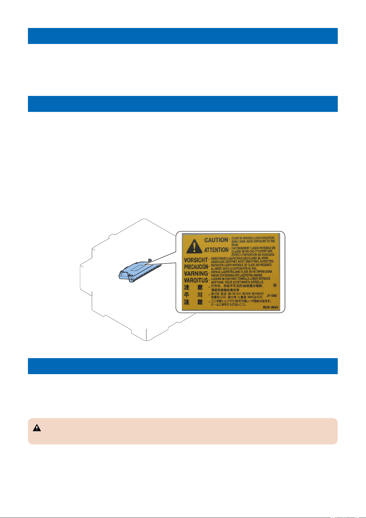
How to Handle the Laser Scanner Unit
This machine is classified as a Class 1 laser product.
However, the laser scanner unit contains source of Class 3B laser beam and exposure to the beam may cause eye injuries.
Therefore, be sure not to disassemble the laser scanner unit. No adjustment can be made to the laser scanner unit in the machine
in the field.
The label shown in the following figure is affixed on the laser scanner unit.
Dieses Gerät ist der Klasse 1 der Laserprodukte zugeordnet.
Allerdings enthält die Laserscannereinheit eine Laserstrahlquelle der Klasse 3B, die Augenschäden verursachen kann, wenn
man in diesen Strahl blickt.
Deshalb darf die Laserscannereinheit nicht zerlegt werden. An der Laserscannereinheit kann keine Justage vor Ort vorgenommen
werden.
Der in folgendem Bild dargestellte Aufkleber ist auf der Laserscannereinheit angebracht.
Power Supply
• As a general rule, do not use extension cords.
If an extension cord must be used, however, use one for local rated voltage and over, untie the cord binding, and insert the
power plug completely into the extension cord outlet to ensure a firm connection between the power cord and the extension
cord.
CAUTION:
Do not plug multiple cords together to an extension cord. It may cause a fire or electrical shock.
• The socket-outlet shall be installed near the equipment and shall be easily accessible.
2
Safety Precautions
Toner Safety
About Toner
Toner is a nontoxic matter composed of plastic, iron and a trace of pigments.
CAUTION:
Never throw toner in flames to avoid explosion.
Handling Adhered Toner
• Use dry tissue paper to wipe off toner adhered to skin or clothes and wash in water.
• Never use warm water for cleaning up toner to prevent toner particles from being gelated to soak into fibers permanently.
• Toner particles are reactive with vinyl polymers. Avoid contacting these materials.
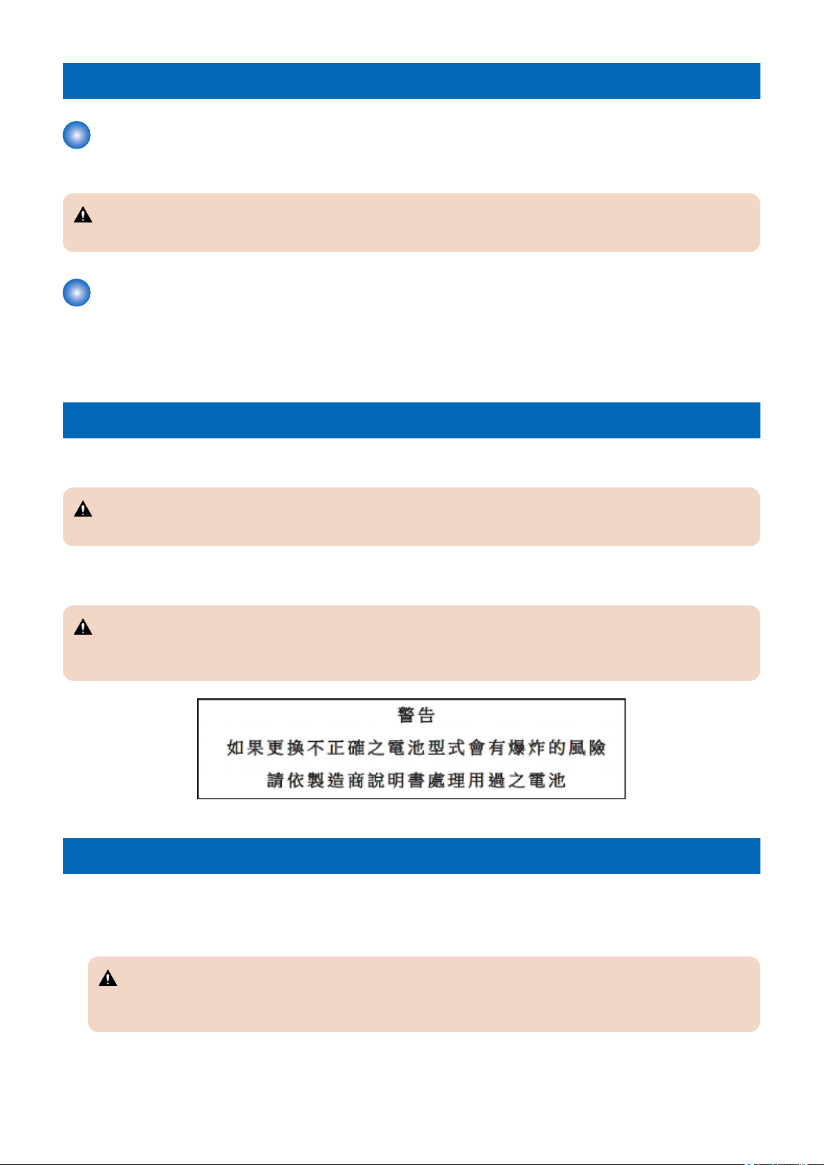
Notes When Handling a Lithium Battery
Dispose of used batteries according to the instructions.
CAUTION:
Risk of explosion if battery is replaced by an incorrect type.
The following warnings are given to comply with Safety Principles (EN60950-1).
CAUTION:
Wenn mit dem falschen Typ ausgewechselt, besteht Explosionsgefahr.
Gebrauchte Batterien gemäß der Anleitung beseitigen.
Notes Before it Works Serving
• At servicing, be sure to turn OFF the power source according to the specified steps and disconnect the power plug.
• Be sure to disconnect the power plug on a regular basis and remove dust and dirt accumulated around the outlet with dry
cloth.
CAUTION:
Leaving the power plug connected for a long time in an environment having a lot of dust, moisture, or oily smoke will
cause a fire. (Because dust accumulated in the surrounding area will absorb moisture and cause an insulation failure)
3
ACHTUNG
Zweipolige bzw. Neutralleiter-Sicherung
Safety Precautions
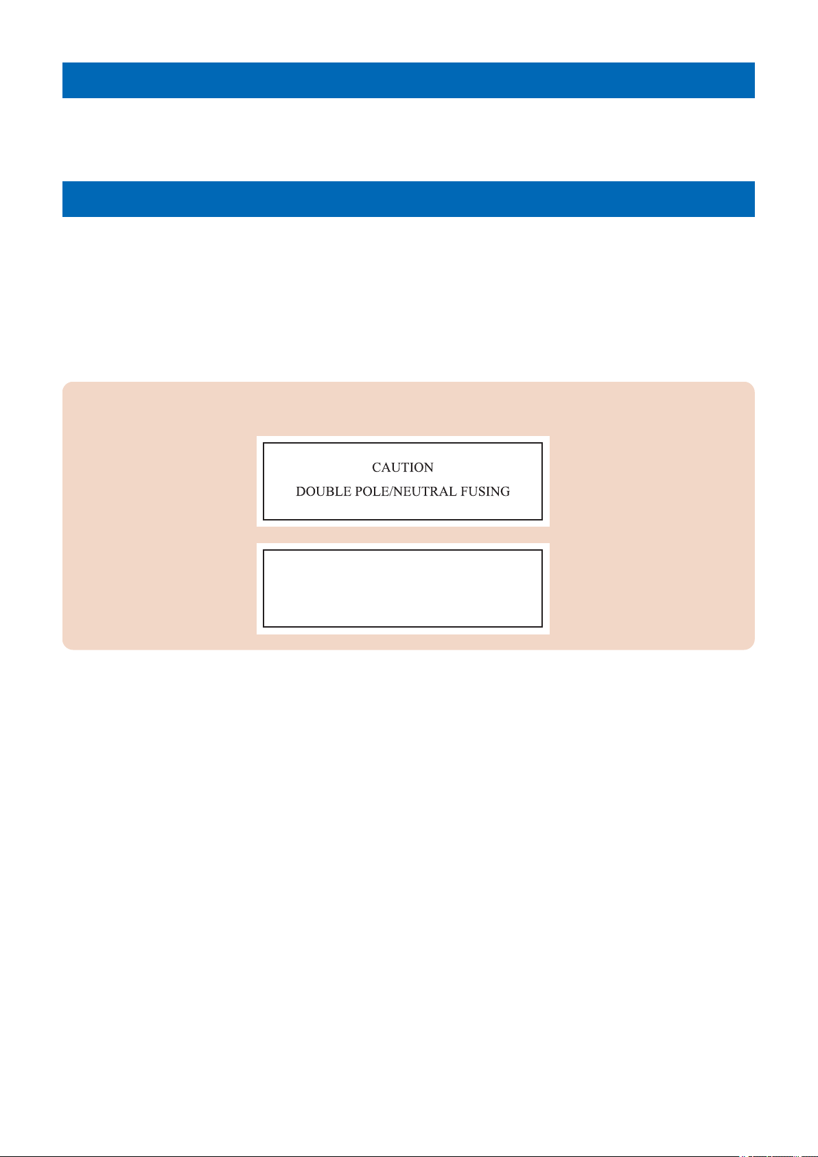
Points to Note at Cleaning
When performing cleaning using organic solvent such as alcohol, be sure to check that the component of solvent is vaporized
completely before assembling.
Notes on Assembly/Disassembly
Follow the items below to assemble/disassemble the device.
1. Disconnect the power plug to avoid any potential dangers during assembling/disassembling works.
2. If not specially instructed, reverse the order of disassembly to reinstall.
3. Ensure to use the right screw type (length, diameter, etc.) at the right position when assembling.
4. To keep electric conduction, binding screws with washers are used to attach the grounding wire and the varistor. Ensure to
use the right screw type when assembling.
5. Unless it is specially needed, do not operate the device with some parts removed.
6. Never remove the paint-locked screws when disassembling.
CAUTION:
Double pole/neutral fusing
4

1
Product Overview
Product Lineups.................................... 6
Specification..........................................7
List of Parts......................................... 11

Product Lineups
Host machine
Function LBP351dn/ LBP351x
LBP352dn/ LBP352x
External
1. Product Overview
Copy -
Print Yes
Fax -
Remote UI Yes
2-sided printing Yes
MEAP Yes
Network Yes
Wireless LAN -
Options
Name Detail
Paper Feeder PF-B1 A Paper Feeder with up to 3 decks can be installed.
Paper Deck Unit PD-G1 High pickup capacity of 1500 sheets
A5 Cassette C-A1 Cassette where A5R size can be loaded
Custom Media Cassette CM-A1 Cassette where A5, A6, and custom size paper can be loaded
Envelope Feeder EF-A1 A large volume of envelopes/postcards can be printed.
Features
High-end A4/LTR B&W SFP of high speed, high durability and high capacity pickup
1. High speed and high durability
This machine is a high-speed printer that realizes a print speed of 62/65 ppm (A4/LTR) in 1-sided printing.
Superior durability, suitable for large volume printing
2. High capacity pickup
In addition to the Multi-purpose Tray and Standard Drawer, up to 3 Paper Feeders (500 sheets) and a Paper Deck Unit (1500
sheets) can be installed as options.
Up to 3,600 sheets (in the case of 80 g/m2) can be continuously and automatically picked up.
3. Improved maintainability
The maintenance kit is commercialized to promote self maintenance by end users.
6

Specification
Product Specifications
Item Specification/Function
Machine installation method Desktop page printer
Photosensitive medium OPC Drum (30 mm dia.)
Exposure method Laser beam
Charging method AC Roller charging
Developing method Dry, 1-component toner projection
Transfer method Roller transfer
Separation method Curvature separation + Static Eliminator
Pickup method Cassette
Pad separation method
Multi-purpose Tray
Pad separation method
Fixing method On-demand fixing method
Delivery method Face down (Delivery Tray) / Face up (Sub Delivery Tray)
Drum cleaning method Cleaning Blade
Toner type One-component magnetic toner
Toner supplying method All-in-one cartridge with drum
Toner level detection function Yes
Toner save mode Yes
Print method Semiconductor laser + Dry-type electrophotographic method
Print resolution 600 dpi x 600 dpi
Print speed*1
(Plain paper (60 to 89 g/m2), At
continuous A4/LTR print)
Warm-up time*2
(Duration from power-on to
standby of the machine)
Recovery time*3
(Time for recovery from deep
sleep to standby)
First print time*3
(At 1-sided A4/LTR print, using
the Delivery Tray)
Paper type Cassette
Paper size Cassette
LBP352dn/ LBP352x
62 sheets/min (A4), 65 sheets/min (LTR)
LBP351dn/ LBP351x
55 sheets/min (A4), 58 sheets/min (LTR)
At normal startup
29 sec. or less
At quick startup
12 sec. or less
10 sec. or less
LBP352dn/ LBP352x
7.0 sec.
LBP351dn/ LBP351x
7.2 sec.
Plain paper (60 to 89 g/m2), Recycled paper (60 to 89 g/m2), Heavy paper (90 to 120 g/m2),
Bond paper (60 to 90 g/m2)
Multi-purpose Tray
Plain paper (60 to 89 g/m2), Recycled paper (60 to 89 g/m2), Heavy paper (90 to 135 g/m2),
Bond paper (60 to 90 g/m2), Label paper, Envelope
A4, B5, A5, LGL, LTR, EXEC, FLS, K16, Custom paper (Width: 148.0 to 216.0 mm, Length: 210.0
to 356.0 mm)
Multi-purpose Tray
A4, B5, A5, A6, LGL, LTR, EXEC, STMT, FLS, K16, Index Card (3" x 5"), Envelope (No.10
(COM10), Monarch, C5, DL), Custom paper (Width: 76.0 to 216.0 mm, Length: 127.0 to 356.0
mm)
1. Product Overview
7

1. Product Overview
Item Specification/Function
Maximum stacking capacity Cassette
500 sheets (80 g/m2), 550 sheets (64 g/m2)
Multi-purpose Tray
100 sheets
Delivery stacking capacity*4 Delivery Tray
Approx. 500 sheets
Sub Delivery Tray
Approx. 100 sheets
2-sided printing A4, B5, A5, LGL, LTR, EXEC, FLS, 16K, Custom paper (Width: 148.0 to 215.9 mm, Length: 210.0 to
355.6 mm)
Host Interface USB Interface
Hi-Speed USB x 4 (1 on the front, 3 on the rear)
Network Interface
Common to 10BASE-T, 100BASE-TX, and 1000BASE-T (RJ-45), Full/Half Duplex
Memory capacity 1 GB
Usage environment temperature
range
Environment humidity range 20 to 80 % RH (Relative humidity; without dew condensation)
Operating noise
(Measured based on ISO7779,
Declared noise emission value
based on ISO9296)
Rated power supply AC 120 to 127 V, 60 Hz
Power consumption
(Reference value)
10 to 30 deg C
LwAd (declared A-weighted sound power level (1 B = 10 dB))
At standby: 4.0 B or less
At printing (1-sided): 7.1 B or less
At printing (2-sided): 7.1 B or less
LpAm (mean A-weighted emission sound-pressure level (bystander position))
At standby: 26 dB
LBP352dn/ LBP352x
At printing (1-sided): 57 dB
At printing (2-sided): 57 dB
LBP351dn/ LBP351x
At printing (1-sided): 56 dB
At printing (2-sided): 56 dB
AC 220 to 240 V, 50/60 Hz
Maximum
1,700 W or less (120 V), 1,650 W or less (230 V)
In operation
LBP352dn/ LBP352x
Approx. 880 W (120 V), approx. 850 W (230 V)
LBP351dn/ LBP351x
Approx. 820 W (120 V), approx. 800 W (230 V)
At standby
Approx. 20 W (120 V), approx. 19 W (230 V)
During sleep mode
Wired LAN connection: Approx. 1.0 W (120 V), approx. 1.1 W (230 V)
USB connection: Approx. 2.0 W (120 V / 230 V)
At power OFF
• At shutdown
0.12 W or less (120 V)
0.17 W or less (230 V)
• In quick off mode
0.66 W or less (120 V)
0.75 W or less (230 V)
Dimensions
(W x D x H)
Weight *5 Approx. 24.5 kg
415 x 529 x 438 mm
*1: The print speed may become lower depending on the settings such as output resolution, paper size, type, orientation, and
number of sheets printed.
8

1. Product Overview
*2: This may vary depending on the usage conditions of this machine (presence/absence of installed options, installation
environment, etc.).
*3: This may vary depending on the print environment.
*4: This may vary depending on the site environment and the type of paper used.
*5: Excluding the Toner Cartridge
Print Speed
LBP352dn/ LBP352x
• At 1-sided printing: 62 sheets/min (A4), 65 sheets/min (LTR)
• At 2-sided printing: 41.4 pages/min (A4), 43.5 pages/min (LTR)
LBP351dn/ LBP351x
• At 1-sided printing: 55 sheets/min (A4), 58 sheets/min (LTR)
• At 2-sided printing: 36.5 pages/min (A4), 38.5 pages/min (LTR)
* The print speed may become lower depending on the settings such as output resolution, paper size, type, orientation, and
number of sheets printed. In the case of 2-sided printing, 1 page on the front side and 1 page on the back side are output as 1
sheet.
Paper type
: Pickup possible -: Pickup not possible)
(
Type of paper Paper set-
tings in this
machine
Plain paper,
recycled paper
Heavy paper
Bond paper
Label paper Labels - - -
Envelope Envelope, En-
2
60 g/m
61 to 70 g/m
71 to 89 g/m
90 to 120 g/m
121 to 135 g/m
60 to 75 g/m
76 to 90 g/m
2
2
2
2
Plain L2 -
Plain paper L -
Plain paper -
2
2
Heavy paper 1 -
Heavy paper 2 - -
Heavy paper 1 -
Heavy paper 2 -
velope H
Cassette Multi-purpose
Tray
- -
Paper Deck
(Option)
Envelope Feed-
(Option)
Paper size
( : Pickup possible -: Pickup not possible)
Paper size Cassette Multi-purpose Tray
A4 210.0 mm x 297.0 mm
B5 182.0 mm x 257.0 mm
A5 148.0 mm x 210.0 mm
A6 105.0 mm x 148.0 mm -
LGL 215.9 mm x 355.6 mm
LTR 215.9 mm x 279.4 mm
STMT 139.7 mm x 215.9 mm -
EXEC 184.1 mm x 266.7 mm
FLS 215.9 mm x 330.2 mm
16K 195.0 mm x 270.0 mm
Index Card (3" x 5") 76.2 mm x 127.0 mm -
Envelope No.10 (COM10) 104.7 mm x 241.3 mm -
Envelope Monarch 98.4 mm x 190.5 mm -
Envelope C5 162.0 mm x 229.0 mm -
er
9

1. Product Overview
Paper size Cassette Multi-purpose Tray
Envelope DL 110.0 mm x 220.0 mm -
Custom paper - *1 *2
*1:
Portrait: Width: 148.0 to 215.9 mm, Length: 210.0 to 355.6 mm
Landscape (Only when using the UFR II printer driver): Width 148.0 to 215.9 mm, Length 148.0 to 215.9 mm
*2:
Portrait: Width 76.2 to 215.9 mm, Length 127.0 to 355.6 mm
Landscape (Only when using the UFR II printer driver): Width 127.0 to 215.9 mm, Length 127.0 to 215.9 mm
10
List of Parts
[9]
[8]
[10]
[11]
[12]
[1]
[3]
[4]
[5]
[2]
[6]
[7]
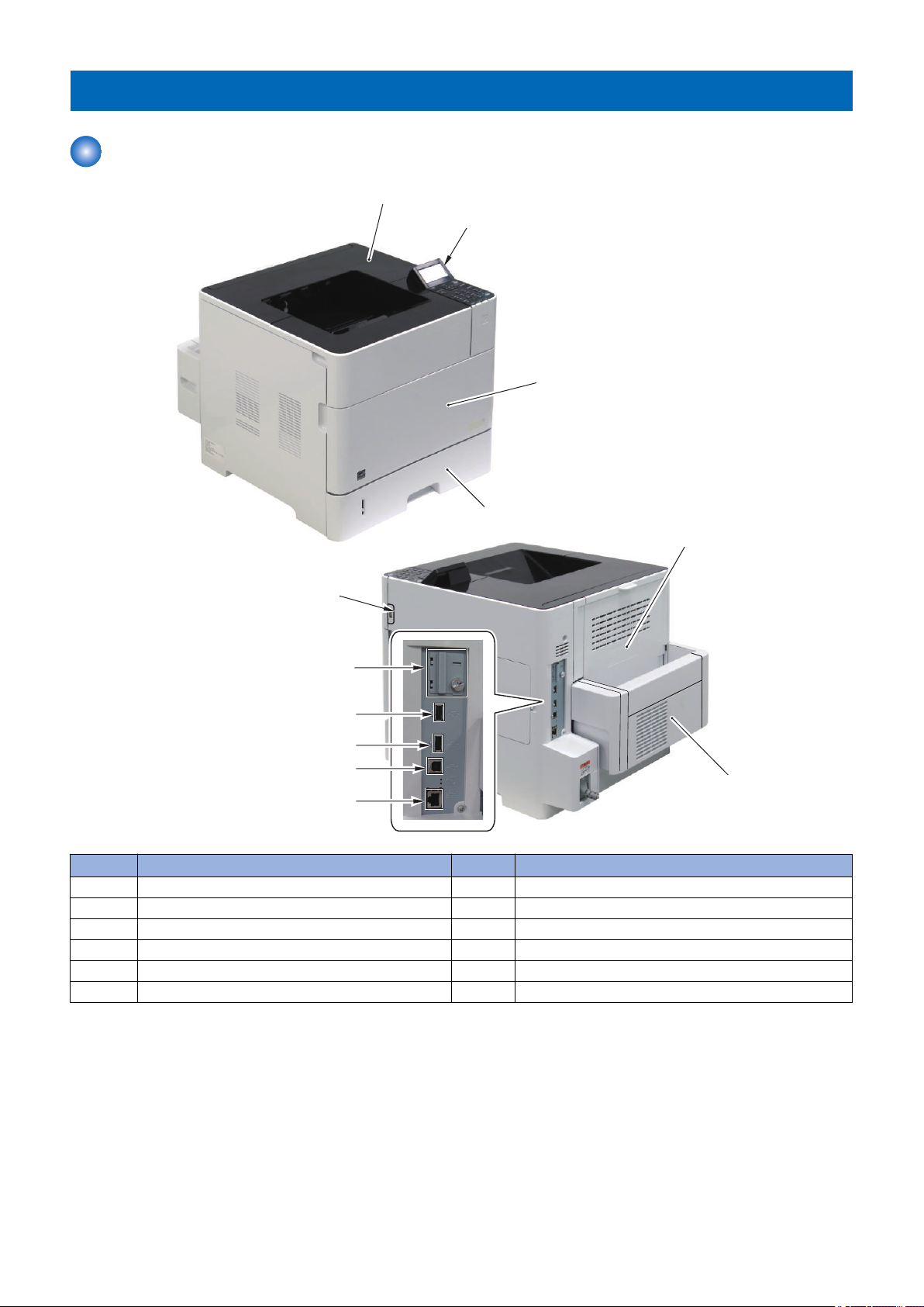
External
1. Product Overview
No. Name 9 Name
1 Upper Cover Unit 7 USB-H (Front)
2 Control Panel 8 Upper Cover
3 Front Cover 9 USB-H (Rear 1)
4 Cassette 10 USB-H (Rear 2)
5 Rear Cover (Sub Delivery Tray) 11 USB-D
6 Duplex Unit 12 LAN Port
11
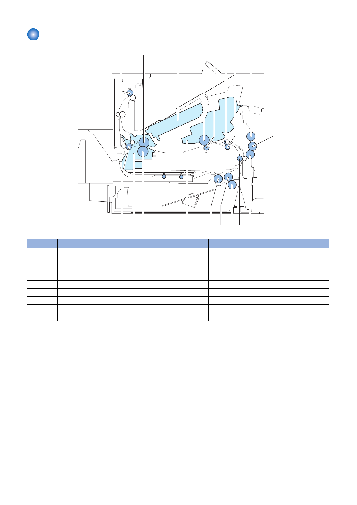
Cross Sectional View
[10]
[1]
[11]
[2]
[12]
[3]
[13]
[4]
[14]
[5]
[15]
[6]
[16]
[7]
[17]
[8]
[18]
[9]
1. Product Overview
No. Name No. Name
[1] Delivery Roller [10] Multi-purpose Tray Separation Roller
[2] Fixing Film [11] Vertical Path Roller
[3] Laser Scanner Unit [12] Cassette Separation Roller
[4] Photosensitive Drum [13] Cassette Feed Roller
[5] Transfer Roller [14] Cassette Pickup Roller
[6] Registration Shutter [15] Cartridge
[7] Registration Roller [16] Pressure Roller
[8] Multi-purpose Tray Pickup Roller [17] Fixing Assembly
[9] Multi-purpose Tray Feed Roller [18] Fixing Delivery Roller
12

Technical
2
Explanation
(Device)
Laser Exposure System......................14
Image Formation System....................16
Pickup Feeding System...................... 21
Fixing System......................................32
Controller System................................36

BD PCB
Scanner mirror
Scanner motor unit
Photosensitive drum
Laser driver
Main Controller
DC controller
LASER CONTROL signal
VIDEO signal
SCANNER MOTOR
SPEED CONTROL signal
BD INPUT signal
2. Technical Explanation (Device)
Laser Exposure System
Overview
The Laser Scanner system forms a latent image on the Photosensitive Drum according to the video signal sent from the Main
Controller.
The Laser Scanner Unit consists of the Laser Unit and the Scanner Motor Unit, and is controlled by the signal input from the DC
Controller.
The following shows an outline drawing of the Laser Scanner Unit.
Laser Scanner Motor Control
Rotates the Polygon Mirror at a specified speed.
14

2. Technical Explanation (Device)
<Execution Timing>
At startup of the Laser Scanner Motor
<Control Description>
1. The DC Controller PCB forcefully rotates the Laser Scanner Motor.
2. Sends acceleration signals (ACC) and deceleration signals (DEC) to the Laser Scanner Motor to control the speed to the
specified speed.
<Related Error Code>
E110-0000: Failure of the Laser Scanner Unit
E110-0001: Error in the initial operation of the Scanner Motor
15
2. Laser-beam exposure
Fixing
6. Fixing
Delivery
7. Drum cleaning
3. Developing
1. Primary charging
Pickup
4.Transfer5. Separation
Transfer
Latent image formation
Media path
Direction of
the drum rotation
Block
Step
Drum cleaning
Developing
Primary charging bias
Photosensitive drum
Primary charging roller
2. Technical Explanation (Device)
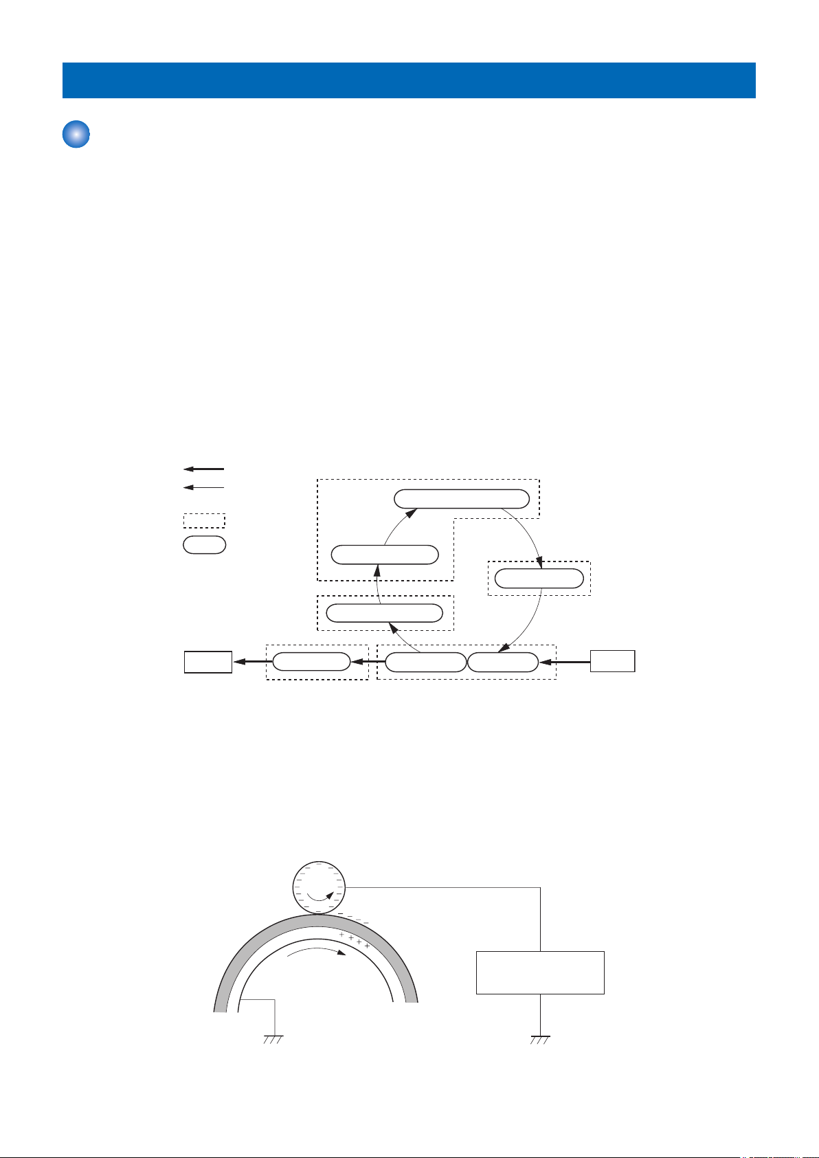
Image Formation System
Image Formation Process
■ Outline
The image formation process consists of the following seven steps divided among five functional blocks:
Latent image formation block
• Step 1: Primary charging
• Step 2: Laser-beam exposure
Developing block
• Step 3: Developing
Transfer block
• Step 4: Transfer
• Step 5: Separation
Fixing block
• Step 6: Fixing
Drum cleaning block
• Step 7: Drum cleaning
■ Latent image formation block
During the two steps that comprise this block, an invisible latent image is formed on the photosensitivedrum.
Step 1: Primary charging
To prepare for latent image formation, the surface of the photosensitive drum is charged with a uniform negative potential. The
primary charging bias is applied to the primary charging roller and the roller charges the drum directly.
16
Laser beam
Unexposed area Exposed area
3KRWRVHQVLWLYH'UXP
/DVHU%HDP
Developing bias
Blade
Developing roller
Photosensitive drum
Unexposed
area
Exposed
area
Exposed
area
Unexposed
area
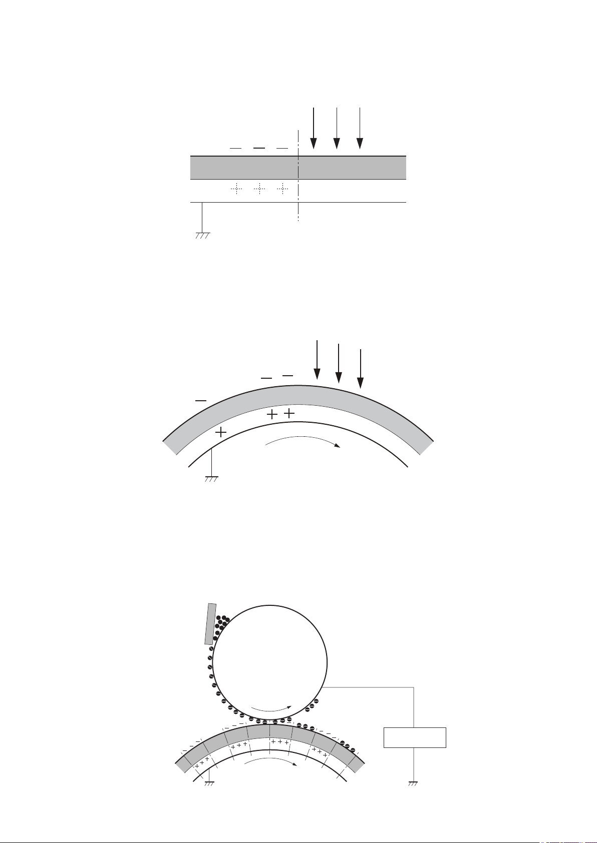
2. Technical Explanation (Device)
Step 2: Laser-beam exposure
The laser beam scans the photosensitive drum to neutralize the negative charge on portions of the drum surface. An electrostatic
latent image forms where the negative charge was neutralized.
● Drum discharge
The drum discharge is a feature to remove residual charge on the Photosensitive Drum surface for preventing the uneven image
density.
The Laser Beam strikes the surface of the Photosensitive Drum to remove the residual charge.
The drum discharge is performed during LSTR period.
■ Developing block
Toner adheres to the electrostatic latent image on the photosensitive drum, which becomes visible.
Step 3: Developing
Toner acquires a negative charge from the friction that occurs when the developing roller rotates against the developing blade.
The negatively charged toner is attracted to the latent image on the photosensitive drum surface because the drum surface has
a higher potential. The developing bias is applied to the developing roller.
17

Transfer bias
Media
Transfer roller
Photosensitive
drum
Media
Transfer roller
Photosensitive
drum
Static charge
eliminator
Fixing bias
Fixing film
Toner
Pressure roller
Fixing heater
Media
2. Technical Explanation (Device)
■ Transfer block
During the two steps that comprise this block, a toner image on the photosensitive drum is transferred to the print media.
Step 4: Transfer
The transfer bias is applied to the transfer roller to charge the print media positive. The positively charged media attracts the
negatively charged toner from the photosensitive drum surface.
Step 5: Separation
The elasticity of the print media and the curvature of the photosensitive drum cause the media to separate from the drum surface.
The static charge eliminator reduces back side static discharge of the media for stable media feed and image quality.
■ Fixing block
The toner image is fixed onto the print media.
Step 6: Fixing
The printer uses an on-demand fixing method. The toner image is permanently affixed to the print media by heat and pressure.
The fixing bias is applied to the fixing film to improve image quality.
18
Toner
collection box
Photosensitive
drum
Cleaning blade
M102
PCB
2. Technical Explanation (Device)
■ Drum cleaning block
The residual toner is cleared from the photosensitive drum surface.
Step 7: Drum cleaning
The cleaning blade scrapes the residual toner off the surface of the photosensitive drum. The residual toner is deposited in the
toner collection box.
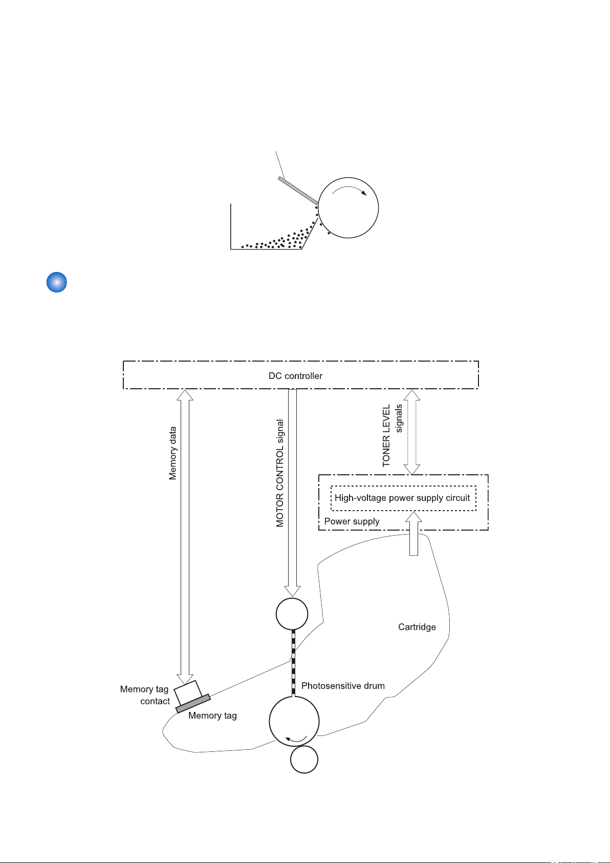
Cartridge
■ Overview
The cartridge of this machine has the function to form a visible image on the Photosensitive Drum with toner.
The following shows an outline drawing of the cartridge of this machine.
The cartridge of this machine consists of the Photosensitive Drum, Primary Charging Roller, Developing Sleeve, Stirring Plate,
Waste Toner Feed Plate, etc.
19

2. Technical Explanation (Device)
The parts other than the Primary Charging Roller are rotated by the drive of the Main Motor, and the Primary Charging Roller
rotates by engaging with the Photosensitive Drum.
The DC Controller detects the toner level by monitoring the toner level detection signal.
■ Memory Tag
This machine can detect and store the cartridge usage conditions and other information when the DC Controller PCB reads and
writes the data stored in the memory tag.
If the memory tag cannot be detected, "Error. Non-Canon cart. not covered by warranty" is displayed.
■ Cartridge Detection
The DC Controller detects whether a cartridge is installed according to the change in primary charging current. The DC Controller
notifies the Main Controller of the absence of a cartridge if it judges there is no cartridge.
Detection timing:
• At power-on
• When the Upper Cover is closed
Display on the Control Panel:
• Insert toner cartridge.
■ Cartridge Life Detection
The DC Controller notifies the Main Controller when cartridge consumption reaches the specified value.
Upon reception of the notification the Main Controller displays a warning or a message that the cartridge has reached the end of
its life.
Warning display*2 End of life display*4, *5
Toner level*1 Differs depending on the setting*3 0%
Detected to (location) Memory tag Memory tag
Message (machine operation) 16 Tnr cart. will soon reach end of lifetime. 1G Change toner cartridge recommended.
*1: Can be checked in [Utility Menu > Consumables > Remaining Toner > Remaining Toner].
*2: Display/Hide can be switched in [Control Menu > Warning Step > Toner Cart. Warning].
*3: Value set in [Setup > User Maintenance > Toner Check Timing/Specify Check Timing].
*4: The operation to perform when the cartridge has reached the end of life can be set in [SERVICE MODE > OPTION GR. >
CRG LIFE STEP].
*5: The cartridge life value can be changed in [SERVICE MODE > OPTION GR. > CRG LIFE STOP].
20
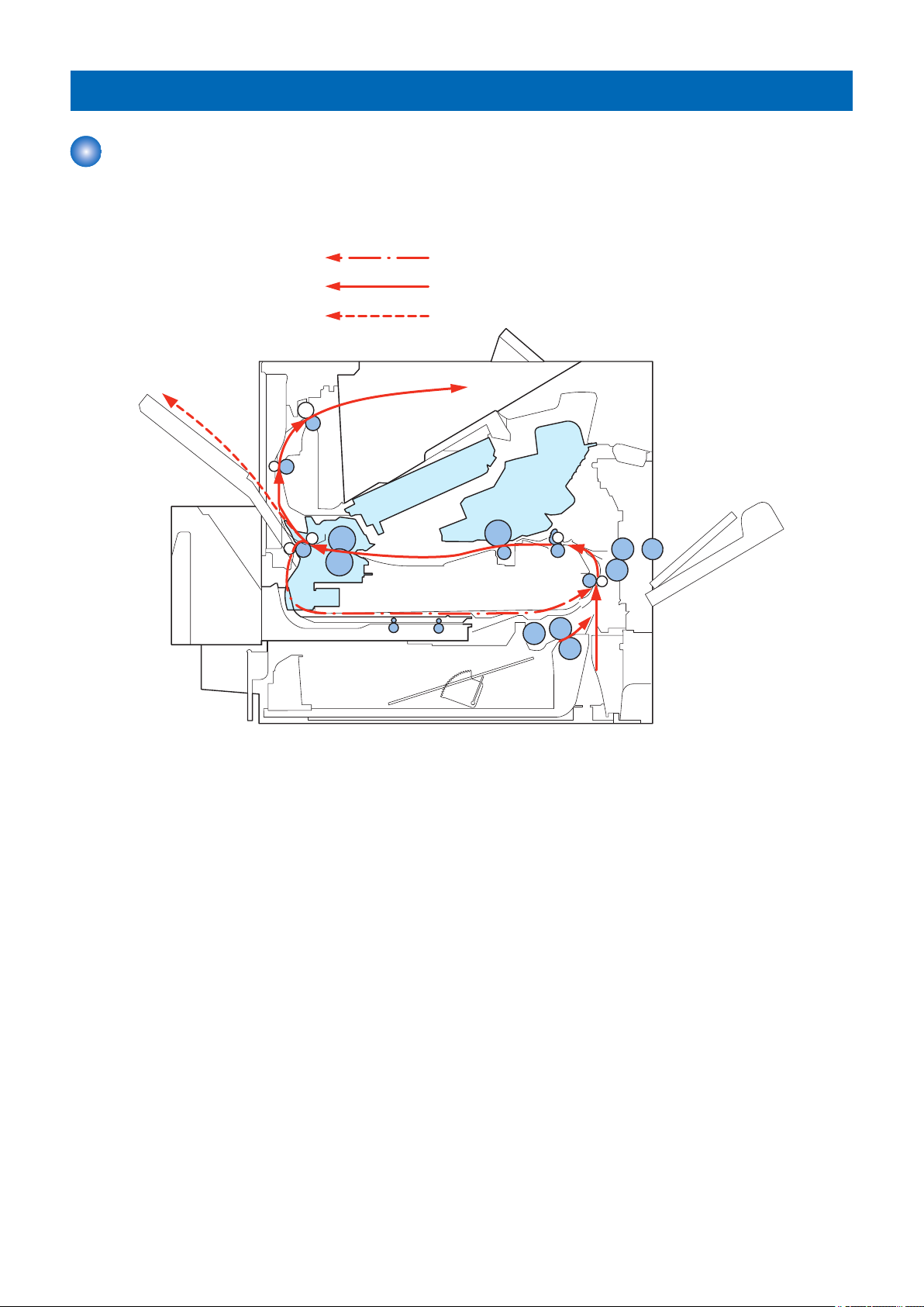
Face-downdelivery
Face-updelivery
Duplexdelivery
2. Technical Explanation (Device)
Pickup Feeding System
Overview
The Pickup Feed System performs pickup, feed, and delivery of print paper, and consists of various rollers.
Print paper flow
21
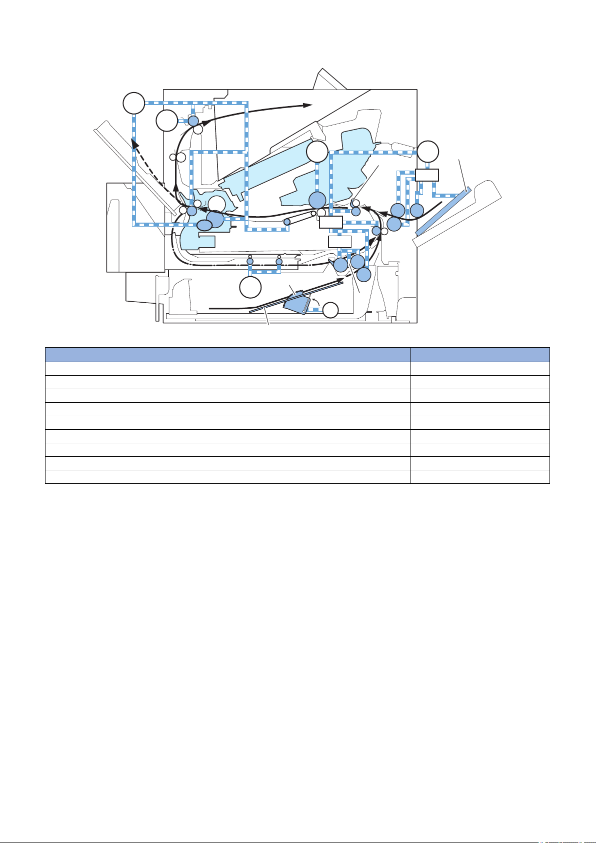
Load drives of electrical components
Cam
CW
CCW
Pickup arm
Lifter
M1501
M299
M102
SL101
Lifting plate
M103
M101
Registration shutter
SL102
Lifting plate
M1502
CL101
2. Technical Explanation (Device)
Name Electric code
Pickup Motor M101
Main Motor M102
Lifter Motor M103
Fixing Motor M299
Duplex Reverse Motor M1501
Duplex Re-pickup Motor M1502
Pickup Clutch CL101
Pickup Solenoid SL101
Multi-purpose Tray Pickup Solenoid SL102
22
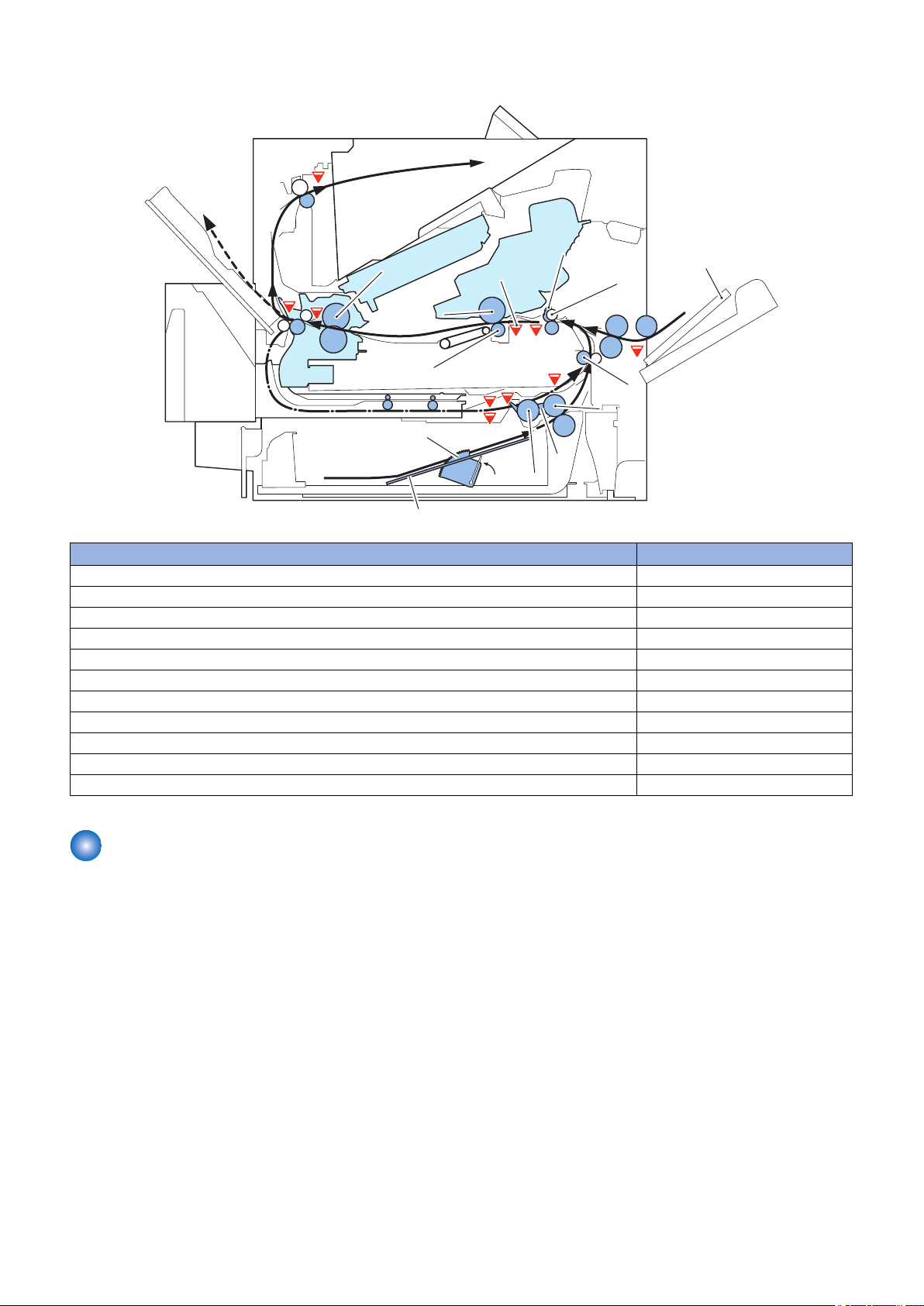
Outline drawing of sensors and rollers
PS101
PS107
PS700
PS104
PS907
PS102
PS103
Pressure roller
Face-down delivery roller
Lifter
Lifting plate
Pickup roller
Pickup arm
Registration shutter
Lifting plate
Photosensitive drum
Fiking sleeve
PS699
Transfer roller
Separation roller
Feed roller
Pre-transfer roller
PS105
Feed roller
PS106
PS108
2. Technical Explanation (Device)
Name Electric code
Paper Sensor PS101
Pre-registration Sensor PS102
Registration Sensor PS103
Delivery Full Sensor PS104
Multi-purpose Tray Sensor PS105
Paper Width Sensor 1 PS106
Media Stack Surface Sensor 1 PS107
Paper Width Sensor 2 PS108
Fixing pressure release sensor PS699
Fixing Outlet Sensor PS700
Media Stack Surface Sensor 2 PS907
Various Control Mechanisms
■ Lifter control
Paper inside a cassette is lifted up by the Lifting Plate.
The Lifting Plate is lifted up by rotating the Cassette Lifter Motor (M103).
The paper surface is detected by the Paper Surface Detection Sensors 1 and 2 (PS107 and PS907).
When the Lifting Plate is rising, the Lifter Motor (M103) is controlled to keep the paper surface steady so that pickup can be
performed stably.
23
 Loading...