


Jan 25 2008
Service Manual
LBP3310/3370 Series


Application
This manual has been issued by Canon Inc. for qualified persons to learn technical theory, installa tion, ma intenance, and repair
of products. This manual covers all localities where the products are sold. For this reason, there may be information in this
manual that does not apply to your locality.
Corrections
This manual may contain technical inaccuracies or typographical errors due to improvements or changes in products. When
changes occur in applicable products or in the contents of this manual, Canon will release technical information as the need
arises. In the event of major changes in the contents of this manual over a long or short period, Canon will issue a new edition
of this manual.
The following paragraph does not apply to any countries where such provisions are inconsistent with local law.
Trademarks
The product names and company names used in this manual are the registered trademarks of the individual companies.
Copyright
This manual is copyrighted with all rights reserved. Under the copyright laws, this manual may not be copied, reproduced or
translated into another language, in whole or in part, without the written consent of Canon Inc.
COPYRIGHT © 2001 CANON INC.
Printed in Japan
Caution
Use of this manual should be strictly supervised to avoid disclosure of confidential information.
Introduction
Symbols Used
This documentation uses the following symbols to indicate special information:
Symbol Description
Indicates an item of a non-specific nature, possibly classified as Note, Caution, or Warning.
Indicates an item requiring care to avoid electric shocks.
Indicates an item requiring care to avoid combustion (fire).
Indicates an item prohibiting disassembly to avoid electric shocks or problems.
Indicates an item requiring disconnection of the power plug from the electric outlet.
Indicates an item intended to provide notes assisting the understanding of the topic in question.
Indicates an item of reference assisting the understanding of the topic in question.
Provides a description of a service mode.
Provides a description of the nature of an error indication.
Memo
REF.

Introduction
The following rules apply throughout this Service Manual:
1. Each chapter contains sections explaining the purpose of specific functions and the relationship between electrical and mechanical systems with reference to the timing of operation.
In the diagrams, represents the path of mechanical drive; where a signal name accompanies the symbol , the arrow indicates the
direction of the electric signal.
The expression "turn on the power" m eans flipping on the power switch, closing the front door, and closing the delivery unit door, which results in
supplying the machine with power.
2. In the digital circuits, '1'is used to indicate that the voltage level of a given signal is "High", while '0' is used to indicate "Low".(The voltage value, however, differs from circuit to circuit.) In addition, the asterisk (*) as in "DRMD*" indicates that the DRMD signal goes on when '0'.
In practically all cases, the internal mechanisms of a microprocessor cannot be checked in the fi eld. Therefore, the operations of the microprocessors
used in the machines are not discussed: they are explained in terms of from sensors to the input of the DC controller PCB and from the output of the
DC controller PCB to the loads.
The descriptions in this Service Manual are subject to change without notice for product improvement or other purposes, and major changes will be communicated in the form of Service Information bulletins.
All service persons are expected to have a good understanding of the contents of this Service Manual and all relevant Service Information bulletins and be
able to identify and isolate faults in the machine."


Contents
Contents
Chapter 1 PRODUCT DESCRIPTION
1.1 Features .....................................................................................................................................................1- 1
1.1.1 Feature....................................................................................................................................................................1- 1
1.2 System Construction ..................................................................................................................................1- 1
1.2.1 System Construction ...............................................................................................................................................1- 1
1.2.2 System Construction ...............................................................................................................................................1- 1
1.3 Product Specifications................................................................................................................................1- 1
1.3.1 Product Specifications.............................................................................................................................................1- 1
1.3.2 Product Specifications.............................................................................................................................................1- 2
1.4 Name of Parts.............................................................................................................................................1- 3
1.4.1 External View............................................................................................... .. ..........................................................1- 3
1.4.2 External View............................................................................................... .. ..........................................................1- 4
1.4.3 Cross Sectional Views.............................................................................................................................................1- 5
1.5 Using the Machine......................................................................................................................................1- 6
1.5.1 Control Panel ...........................................................................................................................................................1- 6
1.5.2 Control Panel ...........................................................................................................................................................1- 6
Chapter 2 TECHNICAL REFERENCE
2.1 Functional Configuration........ ... ... .... ... ... ... .... ... ... ... ... .... ... ... ........................................................................2- 1
2.1.1 Outline.....................................................................................................................................................................2- 1
2.2 Basic Sequense..........................................................................................................................................2- 1
2.2.1 Basic Operation Sequence............................................................................................................................... .......2- 1
2.2.2 Power-on sequence....................................................................................................................................... ..........2- 1
2.3 LASER EXPOSURE SYSTEM...................................................................................................................2- 2
2.3.1 Overview/Configuration...........................................................................................................................................2- 2
2.3.1.1 Outline......................................................................................................................................................................................2- 2
2.3.1.2 Laser Control Circuit ................................................................................................................................................................ 2- 3
2.3.2 Controlling the Laser Activation Timing............................................................................................................ .......2- 5
2.3.2.1 Laser emission control.............................................................................................................................................................2- 5
2.3.2.2 Horizontal synchronous control................................................................................................................................................ 2- 5
2.3.3 Laser Control...........................................................................................................................................................2- 5
2.3.3.1 Automatic power control (APC)................................................................................................................................................2- 5
2.3.3.2 Image masking control............................................................................................................................................................. 2- 5
2.3.4 Laser Scanner Motor Control ..................................................................................................................................2- 6
2.3.4.1 Outline......................................................................................................................................................................................2- 6
2.3.4.2 Scanner motor speed control................................................................................................................................................... 2- 7
2.3.4.3 Scanner motor failure detection...............................................................................................................................................2- 7
2.4 IMAGE FORMATION SYSTEM..................................................................................................................2- 7
2.4.1 Overview/Configuration...........................................................................................................................................2- 7
2.4.1.1 Outline......................................................................................................................................................................................2- 7
2.4.1.2 Print Process............................................................................................................................................................................2- 8
2.4.1.3 Electrostatic latent image formation block ............................................................................................................................... 2- 9
2.4.1.4 Development block ........................................... ..................... ..................... ..................... ........................................................ 2- 9
2.4.1.5 Transfer block ........................................................................................................................................................................ 2- 10
2.4.1.6 Fixing block............................................................................................................................................................................ 2- 11
2.4.1.7 Photosensitive drum cleaning block....................................................................................................................................... 2- 11
2.4.2 High-Voltage Control.............................................................................................................................................2- 12
2.4.2.1 Outline....................................................................................................................................................................................2- 12
2.4.2.2 Primary charging bias generation .......................................................................................................................................... 2- 12
2.4.2.3 Developing bias generation ................................................................................................................................................... 2- 12
2.4.2.4 Transfer charging bias generation ......................................................................................................................................... 2- 13

Contents
2.4.2.5 Fixing bias generation............................................................................................................................................................ 2- 13
2.4.2.6 Cartridge presence detection.................................................................................................................................................2- 13
2.5 PICKUP AND FEEDING SYSTEM...........................................................................................................2- 13
2.5.1 Overview/Configuration..........................................................................................................................................2- 13
2.5.1.1 Outline.................................................................................................................................................................................... 2- 13
2.5.2 Detecting Jams......................................................................................................................................................2- 14
2.5.2.1 Jam Detection Outline............................................................................................................................................................ 2- 14
2.5.2.2 Delay Jams ............................................................................................................................................................................ 2- 15
2.5.2.3 Stationary Jams ..................................................................................................................................................................... 2- 15
2.5.2.4 Other Jams ............................................................................................................................................................................ 2- 15
2.5.3 Cassette Pickup.....................................................................................................................................................2- 15
2.5.3.1 Cassette pick-up .................................................................................................................................................................... 2- 15
2.5.4 Multi-purpose Pickup .............................................................................................................................................2- 16
2.5.4.1 Manual Fees pick-ip............................................................................................................................................................... 2- 16
2.5.5 Duplex Feeding......................................................................................................................................................2- 16
2.5.5.1 Outline.................................................................................................................................................................................... 2- 16
2.5.5.2 Operation ............................................................................................................................................................................... 2- 16
2.6 EXTERNAL AND CONTROLS SYSTEM .................................................................................................2- 17
2.6.1 Fan.........................................................................................................................................................................2- 17
2.6.1.1 Fan motor control................................................................................................................................................................... 2- 17
2.6.2 Power Supply............................................................ ... ................................................... .......................................2- 17
2.6.2.1 Power Supply......................................................................................................................................................................... 2- 17
2.6.2.2 Protective Functions .............................................................................................................................................................. 2- 18
2.7 ENGINE CONTROL SYSTEM .......................................................... ... ... .... ... ... .......................................2- 19
2.7.1 Video Controller.....................................................................................................................................................2- 19
2.7.1.1 Outline.................................................................................................................................................................................... 2- 19
2.7.1.2 Outline of Operation by Block ................................................................................................................................................ 2- 19
2.7.1.3 Overview................................................................................................................................................................................ 2- 20
2.7.1.4 Outline of Operation by Block ................................................................................................................................................ 2- 20
2.7.2 Engine Controller..................... ... .................................................. ... ......................................................................2- 21
2.7.2.1 Outline.................................................................................................................................................................................... 2- 21
2.8 FIXING UNIT/DELIVERY SYSTEM..........................................................................................................2- 23
2.8.1 Overview/Configuration..........................................................................................................................................2- 23
2.8.1.1 Outline.................................................................................................................................................................................... 2- 23
2.8.2 Various Control Mechanisms.................................................................................................................................2- 24
2.8.2.1 Fixing Temperature Control ................................................................................................................................................... 2- 24
2.8.2.2 Protective Functions .............................................................................................................................................................. 2- 25
Chapter 3 DISASSEMBLY AND ASSEMBLY
3.1 EXTERNAL AND CONTROLS SYSTEM ...................................................................................................3- 1
3.1.1 Rear Cover........................................................................................................................ ... ....................................3- 1
3.1.1.1 Preparation for removing the rear cover unit ...........................................................................................................................3- 1
3.1.1.2 Removing the rear cover unit................................................................................................................................................... 3- 1
3.1.2 Right Cover..................................................................................................................................... .........................3- 1
3.1.2.1 Detaching the right cover......................................................................................................................................................... 3- 1
3.1.3 Left Cover ................................................................................................................................................................3- 2
3.1.3.1 Detaching the left cover ........................................................................................................................................................... 3- 2
3.1.4 Upper Cover.............................................................................................................................................................3- 3
3.1.4.1 Preparation for detaching the upper cover unit........................................................................................................................ 3- 3
3.1.4.2 Detaching the upper cover.......................................................................................................................................................3- 3
3.1.4.3 Detaching the upper cover.......................................................................................................................................................3- 3
3.1.5 Front Cover..................................................................................................................................... .........................3- 4
3.1.5.1 Preparation for detaching the front cover unit.......................................................................................................................... 3- 4
3.1.5.2 Detaching the front cover unit.................................................................................................................................................. 3- 4
3.1.6 Main Drive Unit ........................................................................................................................................................3- 5
3.1.6.1 Preparation for removing the main drive assembly..................................................................................................................3- 5
3.1.6.2 Removing the main drive assembly.........................................................................................................................................3- 5
3.1.7 Duplexing Drive Unit............................................................................................................... ... ..............................3- 6

Contents
3.1.7.1 Removing the duplexing drive assembly ................................................................................................................................. 3- 6
3.1.8 Operation Panel Unit ...............................................................................................................................................3- 7
3.1.8.1 Preparation for detaching the control panel.............................................................................................................................3- 7
3.1.8.2 Detaching the control panel ..................................................................................................................................................... 3- 7
3.1.8.3 Detaching the control panel ..................................................................................................................................................... 3- 7
3.1.9 Engine controller board ...........................................................................................................................................3- 8
3.1.9.1 Preparation for removing the engine controller PCB ...............................................................................................................3- 8
3.1.9.2 Removing the engine controller PCB............................................................................... ........................................................3- 8
3.1.10 Duplexing Driver Board..........................................................................................................................................3- 9
3.1.10.1 Preparation for removing the duplexing driver PCB...............................................................................................................3- 9
3.1.10.2 Removing the duplexing driver PCB .................................................................................................................................... 3- 10
3.1.11 Video Controller Board ........................................................................................................................................3- 10
3.1.11.1 Removing the video controller PCB ..................................................................................................................................... 3- 10
3.1.11.2 Removing the video controller PCB ..................................................................................................................................... 3- 10
3.1.12 USB Board...........................................................................................................................................................3- 11
3.1.12.1 Removing the USB PCB ...................................................................................................................................................... 3- 11
3.1.13 Door Switch .......................................................... ................................................... ............................................3- 12
3.1.13.1 Removing the door switch.................................................................................................................................................... 3- 12
3.1.14 Main Body Fan................................................................................................ .....................................................3- 12
3.1.14.1 Preparation for removing the fan.......................................................................................................................................... 3- 12
3.1.14.2 Removing the fan................................................................................................................................................................. 3- 12
3.2 LASER EXPOSURE SYSTEM.................................................................................................................3- 13
3.2.1 Laser Scanner Unit................................................................................................................................................3- 13
3.2.1.1 Preparation for removing the laser scanner unit....................................................................................................................3- 13
3.2.1.2 Removing the laser scanner unit ...........................................................................................................................................3- 13
3.3 IMAGE FORMATION SYSTEM................................................................................................................3- 13
3.3.1 Transfer Charging Roller.......................................................................................................................................3- 13
3.3.1.1 Removing the transfer charging roller....................................................................................................................................3- 13
3.4 PICKUP AND FEEDING SYSTEM...........................................................................................................3- 13
3.4.1 Cassette Pickup Roller..........................................................................................................................................3- 13
3.4.1.1 Removing the cassette pickup roller......................................................................................................................................3- 13
3.4.2 Cassette Pickup solenoid......................................................................................................................................3- 14
3.4.2.1 Preparation for removing the cassette pickup solenoid ......................................................................................................... 3- 14
3.4.2.2 Removing the cassette pickup solenoid................................................................................................................................. 3- 14
3.4.3 Cassette Separation Pad.......................................................................................................................................3- 14
3.4.3.1 Removing the cassette separation pad.................................................................................................................................. 3- 14
3.4.4 Manual Pickup Roller.............................................. ... .................................................. ... ... ....................................3- 14
3.4.4.1 Removing the manual pickup roller........................................................................................................................................ 3- 14
3.4.5 Manual Separation Pad.........................................................................................................................................3- 15
3.4.5.1 Preparation for removing the manual separation pad............................................................................................................ 3- 15
3.4.5.2 Removing the manual separation pad ................................................................................................................................... 3- 15
3.4.6 Registration Roller.................................................................................................................................................3- 15
3.4.6.1 Preparation for removing the registration roller......................................................................................................................3- 15
3.4.6.2 Removing the registration roller.............................................................................................................................................3- 15
3.4.7 Main Motor.............................................................................................................................................................3- 16
3.4.7.1 Preparation for removing the main motor .............................................................................................................................. 3- 16
3.4.7.2 Removing the main motor...................................................................................................................................................... 3- 16
3.4.8 Reversal Solenoid .................................................................................................................................................3- 16
3.4.8.1 Preparation for removing the reverse solenoid......................................................................................................................3- 16
3.4.8.2 Removing the reverse solenoid .............................................................................................................................................3- 16
3.4.9 Duplexing Unit.......................................................................................................................................................3- 16
3.4.9.1 Preparation for removing the duplexing unit .......................................................................................................................... 3- 16
3.4.9.2 Removing the duplexing unit.................................................................................................................................................. 3- 16
3.5 FIXING SYSTEM......................................................................................................................................3- 17
3.5.1 Fixing Unit.............................................. ... ................................................... .. ........................................................3- 17
3.5.1.1 Preparation for removing the fixing assembly........................................................................................................................ 3- 17
3.5.1.2 Removing the fixing assembly ............................................................................................................................................... 3- 17
3.5.1.3 Removing the fixing assembly ............................................................................................................................................... 3- 18
3.5.2 Fixing Film Unit......................................................................................................................................................3- 19

Contents
3.5.2.1 Preparation for removing the fixing film unit...........................................................................................................................3- 19
3.5.2.2 Removing the fixing film unit..................................................................................................................................................3- 19
3.5.3 Fixing Pressure Roller................................. ... ... .................................................. ... ................................................3- 20
3.5.3.1 Preparation for removing the fixing pressure roller................................................................................................................3- 20
3.5.3.2 Removing the fixing pressure roller .......................................................................................................................................3- 20
Chapter 4 MAINTENANCE AND INSPECTION
4.1 Periodically Replaced Parts .......................................... .... ... ... ... .... ... .........................................................4- 1
4.1.1 Periodically Replaced Parts.....................................................................................................................................4- 1
4.2 Consumables .............................................................................................................................................4- 1
4.2.1 Life Expectancy of Consumable Parts.....................................................................................................................4- 1
4.3 Periodical Service.......................................................................................................................................4- 1
4.3.1 Periodic Service.......................................................................................................................................................4- 1
4.4 Cleaning .....................................................................................................................................................4- 1
4.4.1 Cleaning During Service Visit ..................................................................................................................................4- 1
Chapter 5 TROUBLESHOOTING
5.1 MEASUREMENT AND ADJUSTMENT............................. ... ... ... .... ... ... ... .... ......................................... .... ..5- 1
5.1.1 Test Print.................................. ... .................................................. ...........................................................................5- 1
5.1.1.1 Test Print.................................................................................................................................................................................. 5- 1
5.1.1.2 Test Print.................................................................................................................................................................................. 5- 1
5.1.2 Mechanical Adjustment......................................................... .. ... ..............................................................................5- 1
5.1.2.1 Checking the Nip Width (fixing pressure roller)........................................................................................................................ 5- 1
5.2 SERVICE TOOLS ......................................................................................................................................5- 2
5.2.1 Standard Tools.........................................................................................................................................................5- 2
5.2.2 Special Tools ........................................................................................................................................ ...................5- 2
5.3 ERROR CODE TABLE.. ... ... .... ... .......................................... ... ... .... ... ... ... ................................................... 5- 2
5.3.1 Error Code ............................................................................................................................................ ...................5- 2
5.3.2 Error Code ............................................................................................................................................ ...................5- 3
5.3.3 A4-XX_ERROR....................................................................................................................... ... ..............................5- 4
5.3.4 A5-XX_ERROR....................................................................................................................... ... ..............................5- 4
5.3.5 A7-XX_ERROR....................................................................................................................... ... ..............................5- 4
5.3.6 D7-XX_ERROR .................................................................................................................................... ... ................5- 4
5.3.7 D8-XX_ERROR .................................................................................................................................... ... ................5- 4
5.4 Version Up........ ... .... ... ... ... .......................................... ... .... .......................................... ...............................5- 5
5.4.1 Overview of Upgrading Work...................................................................................................................................5- 5
5.4.2 Construction of Firmware....................................................................................................................................... ..5- 5
5.4.3 Outline of the Service Support Tool.........................................................................................................................5- 5
5.4.4 Registering the Firmware........................................................................................................................................5- 7
5.4.5 Making Connections ................................................................................................................................................5- 9
5.4.6 The down load procedure of the system................................................................................................................5- 10
5.5 Service Mode ...........................................................................................................................................5- 13
5.5.1 PCL........................................................................................................................................................................5- 13
5.5.1.1 Overview................................................................................................................................................................................ 5- 13
5.5.1.2 Service Mode......................................................................................................................................................................... 5- 13
Chapter 6 APPENDIX
6.1 OUTLINE OF ELECTRICAL COMPONENTS............................................................................................6- 1
6.1.1 Clutch/Solenoid........................................................................................................................................... ... ..........6- 1
6.1.1.1 Solenoid................................................................................................................................................................................... 6- 1
6.1.2 Motor............................................................................................................................................... ... ......................6- 1
6.1.2.1 Motor........................................................................................................................................................................................ 6- 1
6.1.3 Fan............................................................................................................................................. ..............................6- 2
6.1.3.1 Fan........................................................................................................................................................................................... 6- 2

Contents
6.1.4 Sensor.....................................................................................................................................................................6- 2
6.1.4.1 Sensor......................................................................................................................................................................................6- 2
6.1.5 PCBs .......................................................................................................................................................................6- 3
6.1.5.1 PCB................................................................... .......................................................................................................................6- 3

Contents

Chapter 1 PRODUCT DESCRIPTION


Contents
Contents
1.1 Features..........................................................................................................................................................................1-1
1.1.1 Feature.......................................................................................................................................................................................... 1-1
1.2 System Construction......................................................................................................................................................1-1
1.2.1 System Construction .................................................................................................................................................................... 1-1
1.2.2 System Construction .................................................................................................................................................................... 1-1
1.3 Product Specifications....................................................................................................................................................1-1
1.3.1 Product Specifications ................................................................................................................................................................. 1-1
1.3.2 Product Specifications ................................................................................................................................................................. 1-2
1.4 Name of Parts.................................................................................................................................................................1-3
1.4.1 External View .............................................................................................................................................................................. 1-3
1.4.2 External View .............................................................................................................................................................................. 1-4
1.4.3 Cross Sectional Views ................................................................................................................................................................. 1-5
1.5 Using the Machine.........................................................................................................................................................1-6
1.5.1 Control Panel ............................................................................................................................................................................... 1-6
1.5.2 Control Panel ............................................................................................................................................................................... 1-6

Chapter 1
1-1
1.1 Features
1.1.1 Feature
0018-3077
LBP3370 / LBP3310
1. Compact, high-speed and high-resolution printer
Regardless of its compact size that enables an installation on side of desks, this printer realizes the printing speed of 21 pages per minute in letter-size paper with
the resolution of 600 dpi.
2. Short wait time and low power consumption
The printer utilizes the on-demand fixing method that turns on the heater only during print operations. This shortens wait time, and enables low power
consumption during stand by period.
3. Automatic duplex printing
The printer enables an automatic duplex printing by installing the duplexing unit as a standard equipment in the printer.
1.2 System Construction
1.2.1 System Construction
0018-3078
LBP3310
F-1-1
T-1-1
1.2.2 System Construction
0018-3079
LBP3370
F-1-2
T-1-2
1.3 Product Specifications
1.3.1 Product Specifications
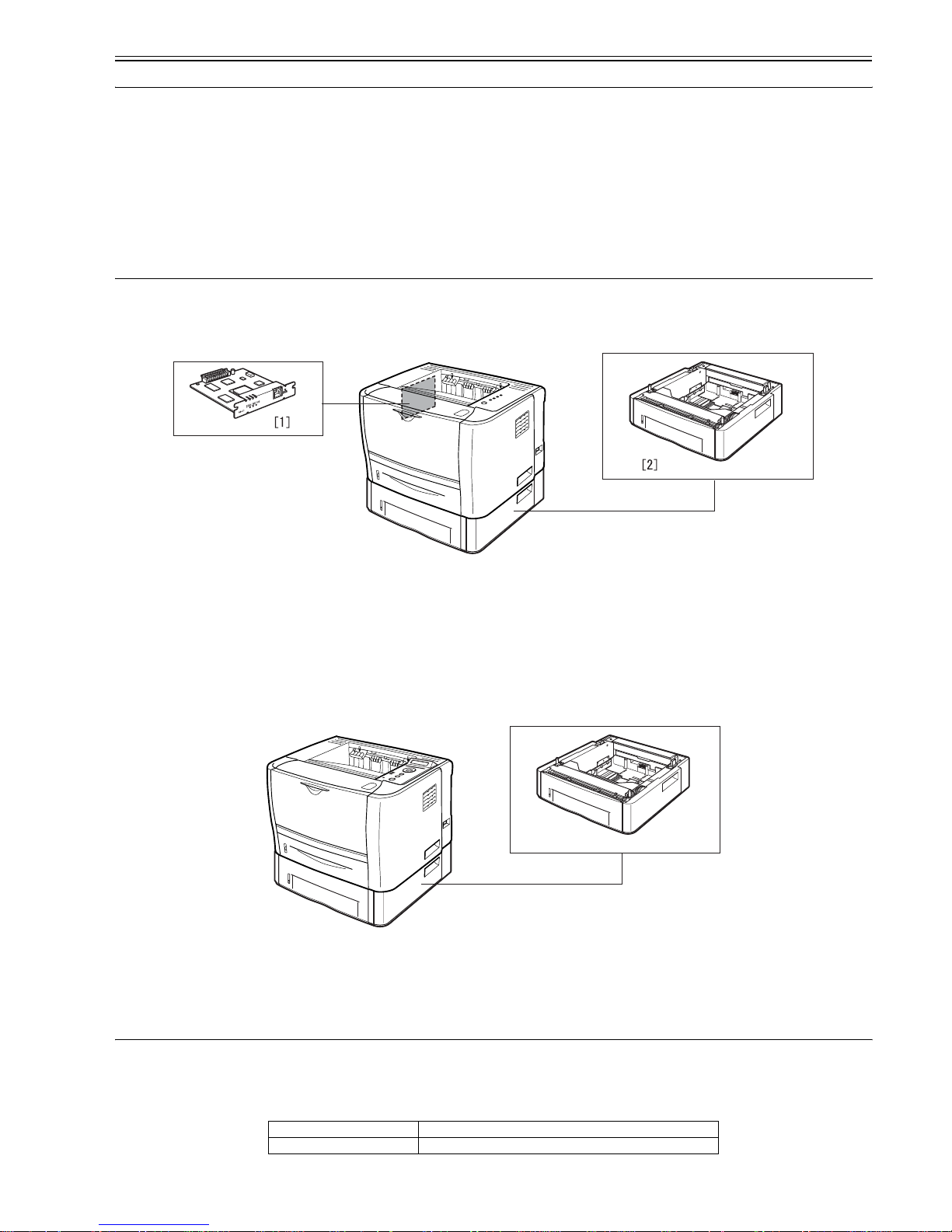
0018-3080
LBP3310
[1] Network Board NB-C2
[2] Paper Feeder PF-35P
[1] Paper Feeder PF-35P
Body installation method desktop page printer
Photosensitive medium OPC drum
[1]

Chapter 1
1-2
1.3.2 Product Specifications
0018-3219
LBP3370
Exposure method semiconductor laser
Development method Toner projection development
Transfer method by roller
Separation method by curvature
Cassette pickup method by pad
Multifeeder pickup method by pad
Drum cleaning method by blade
Fixing method on-demand
Delivery method face-down/face-up
Toner supply type by toner cartridge
3k cartridge: about 3000 prints
7k cartridge: about 7000 prints
(A4, single-sided; at 5% image ratio)
Warm-up time in standby: 0 sec (at power-on: 8 sec or less)
Print area top: 5 mm; bottom: 5 mm; left/right: 5 mm (if envelope, top, bottom, left,
right: 10 mm)
Printing resolution 600dpi
First print time 6.5 sec or less (approx.; A4)
Print speed (A4) 26 pages/min (approx.)
Cassette paper size Standard sizes
A4, B5, A5, Legal, Letter, Executive
Custom sizes
Width 148.0 to 215.9 mm; Length 210.0 to 355.6 mm
Multi-purpose paper size A4, B5, A5, Legal, Letter, Executive, Envelope DL, Envelope COM10,
Envelope C5, Envelope Monarch, Index Card, Custom Paper Size (width
76.2 to 215.9 mm, length 127.0 to 355.6 mm)
Cassette paper type plain paper (64 to 90 g/m2), heavy paper (91 to 120 g/m2), recycled
paper,
Multi-purpose paper type plain paper (64 to 90 g/m2), heavy paper (91 to 163 g/m2), recycled
paper, transparency, label paper, envelop (DL, COM10, C5, Monarch,
B5)
Cassette capacity 250 sheets (approx.; plain paper, 64 g/m2)
Multi-purpose capacity 50 sheets (approx.; plain paper, 64 g/m2)
Delivery tray stack Face-down output tray: approx. 125 sheets (64 g/m2)
Face-up output slot: 1 sheet
Duplex method Auto duplexing
Interface Standard : USB2.0, Option : 10Base-T/100Base-TX
Memory 8 MB (internal; no optional memory available)
Hard disk standard : none, option : none
Operating environment
(Temperature range)
10 to 32.5 deg C
Operating environment
(Humidity range)
20% to 80% RH
Noise 55 dB or less (during printing; based on ISO9296; announced noise
emission)
Power supply rating AC120V±10% (50/60Hz ±2Hz)
AC230V±10% (50/60Hz ±2Hz)
Power consumption (Maximum) 120V: 845W or less
230V: 909W or less
(approx.; 20 deg C; for input of rated power supply; including peak value
lasting 1 sec or more)
Power consumption 120V
Average suring operation: approx. 386W
Average suring standby: approx. 4W
230V
Average suring operation: approx. 382W
Average suring standby: approx. 4W
Dimensions 399.7 (W) x 378.6 (D) x 258 (H)mm
Weight printer: Approx;11.2kg (excluding the toner cartridge); toner cartridge:
Approx,0.8kg(3K cartridge), Approx,1.0kg(7K cartridge)
Option paper feeder
Body installation method desktop page printer
Photosensitive medium OPC drum
Exposure method semiconductor laser
Development method Toner projection development

Chapter 1
1-3
1.4 Name of Parts
1.4.1 External View
0018-3082
LBP3310
Transfer method by roller
Separation method by curvature
Cassette pickup method by pad
Multifeeder pickup method by pad
Drum cleaning method by blade
Fixing method on-demand
Delivery method face-down/face-up
Toner supply type by toner cartridge
3k cartridge: about 3000 prints
7k cartridge: about 7000 prints
(A4, single-sided; at 5% image ratio)
Warm-up time in standby: 0 sec (at power-on: 9 sec or less)
Print area top: 5 mm; bottom: 5 mm; left/right: 5 mm (if envelope, top, bottom, left,
right: 10 mm)
Printing resolution 600dpi
First print time 6.5 sec or less (approx.; A4)
Print speed (A4) 26 pages/min (approx.)
Cassette paper size Standard sizes
A4, B5, A5, Legal, Letter, Executive
Custom sizes
Width 148.0 to 215.9 mm; Length 210.0 to 355.6 mm
Multi-purpose paper size Standard sizes
A4, B5, A5, Legal, Letter, Executive, Envelope DL, Envelope COM10,
Envelope C5, Envelope Monarch, Envelope B5, Index Card, Statement,
16K
Custom sizes
Width 76.2 to 215.9 mm; Length 127.0 to 355.6 mm
Cassette paper type plain paper (64 to 90 g/m2), heavy paper (91 to 120 g/m2), recycled
paper
Multi-purpose paper type plain paper (64 to 90 g/m2), heavy paper (91 to 163 g/m2), recycled
paper, transparency, label paper, envelop (DL, COM10, C5, Monarch,
B5)
Cassette capacity 250 sheets (approx.; plain paper, 64 g/m2)
Multi-purpose capacity 50 sheets (approx.; plain paper, 64 g/m2)
Delivery tray stack Face-down output tray: approx. 125 sheets (64 g/m2)
Face-up output slot: 1 sheet
Duplex method Auto duplexing
Interface Standard : USB2.0, 10Base-T/100Base-TX
Memory 8 MB (internal; no optional memory available)
Hard disk standard : none, option : none
Operating environment
(Temperature range)
10 to 32.5 deg C
Operating environment
(Humidity range)
20% to 80% RH
Noise 55 dB or less (during printing; based on ISO9296; announced noise
emission)
Power supply rating AC230V±10% (50/60Hz ±2Hz)
Power consumption (Maximum) 950W or less
(approx.; 20 deg C)
Power consumption Average suring operation: approx. 403W
Average suring standby: approx. 9W
Dimensions 399.7 x 378.6 x 267 mm
Weight printer: Approx;11.4kg (excluding the toner cartridge); toner cartridge:
Approx,0.8kg(3K cartridge), Approx,1.0kg(7K cartridge)
Option paper feeder
Chapter 1
1-4
F-1-3
F-1-4
1.4.2 External View
0018-3084
LBP3370
F-1-5
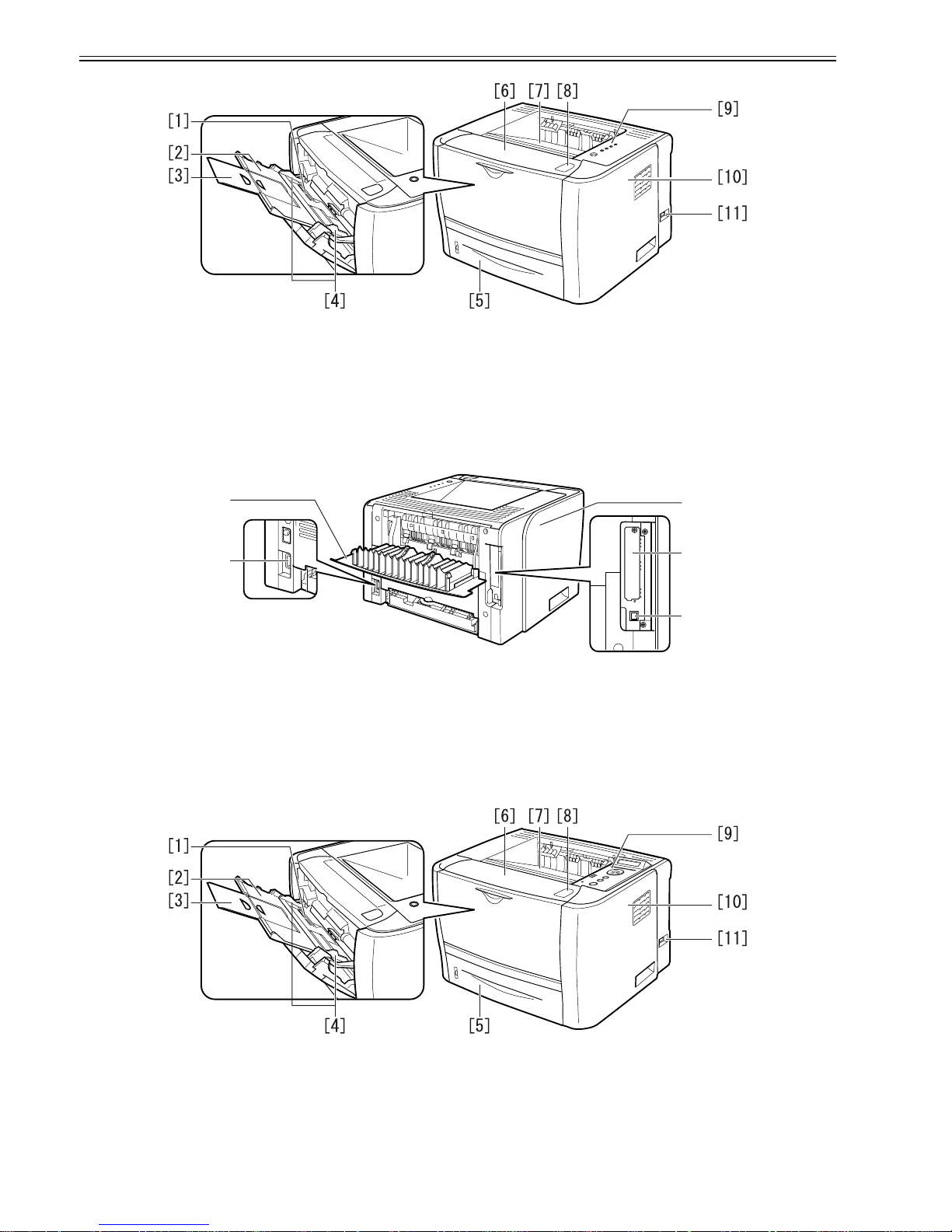
[1] Manual feeder tray [7] Face-down Output Tray
[2] Sub tray [8] Open Button
[3] Extension tray [9] Control Panel
[4] Paper guide [10] Right cover
[5] Paper Cassette [11] Power Switch
[6] Front Cover
[1] Face-up Output Tray [4] Expansion Slot
[2] Power Socket [5] USB Connector
[3] Left cover
[1] Manual feeder tray [7] Face-down Output Tray
[2] Sub tray [8] Open Button
[3] Extension tray [9] Control Panel
[4] Paper guide [10] Right cover
[2]
[1]
[3]
[4]
[5]
Chapter 1
1-5
F-1-6
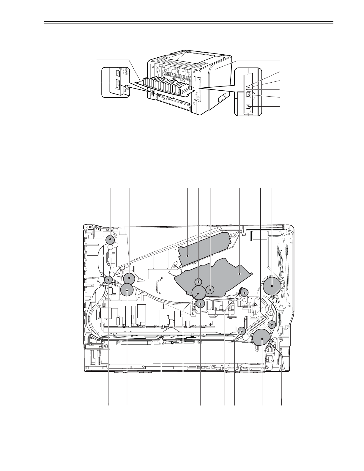
1.4.3 Cross Sectional Views
0018-3085
LBP3370 / LBP3310
F-1-7
[5] Paper Cassette [11] Power Switch
[6] Front Cover
[1] Face-up Output Tray [5] 10 Indicatotor
[2] Power Socket [6] TX/RX Indicatotor
[3] Left Cover [7] LAN Connector
[4] 100 Indicatotor [8] USB Connector
[1] Face-down delivery roller [11] Pick-up roller
[2] Fixing film unit [12] Registration roller
[5]
[6]
[4]
[8]
[7]
[2]
[1]
[3]
[17] [16] [15] [14] [13] [12] [11] [10]
[9]
[1] [2] [3] [4] [5] [6] [8][7]
[18][19]

Chapter 1
1-6
1.5 Using the Machine
1.5.1 Control Panel
0018-3086
LBP3310
F-1-8
1.5.2 Control Panel
0018-3087
LBP3370
F-1-9
[3] Laser/scanner unit [13] Duplex pick-up roller
[4] Primary charging roller [14] Registration shutter
[5] Developing cylinder [15] Transfer charging roller
[6] Toner cartridge [16] Photosensitive drum
[7] Feed roller [17] Duplex feed roller
[8] Manual pickup roller [18] Pressure roller
[9] Manual separation pad [19] Face-up delivery roller
[10] Separation pad
[1] Load Paper Indicator
On
There is no paper in any paper source.
Blinking:
No paper or paper of an inappropriate size s loaded
[2] Paper Jam Indicator
Blinking
A paper jam is occurring, disabling printing.
[3] Alarm Indicator
On
Service call is occurring.
Blinking
An error is occurring, disabling printing.
[4]Ready Indicator
On
The printer is ready to print.
Blinking
The printer is busy performing some kind of processing or operation, such as
printing, warming up, cleaning, or pausing a job.
[5] Cancel Job Key/Cancel Job Indicator Pressing this key enables the cancellation of the jobs in which an error is
occurring and those in progress. The indicator comes on while pressing the ke y.
The indicator blinks while a job is in the cancellation process.
[1]
[2]
[3]
[4]
[5]
[1]
[14]
[11]
[10]
[12]
[3]
[5]
[6]
[4]
[13]
[7]
[8]
[2]
[9]

Chapter 1
1-7
[1] Display
Displays the printer status, messages, the items and setting values of the menu functions.
[2] Job Indicator (Green)
On:
The printer is receiving print data, or any print data remains in the printer memory.
Blinking:
The printer is processing print data.
Off:
There is no print data in the printer memory.
[3] Message Indicator (Orange)
On:
The printer cannot print because a problem has occurred in the printer.
(If the printer has entered Power Save Mode 1 when it is offline, only the Message indicator (orange) and Power indicator (green) are on.)
Off:
The printer is in a normal state.
[4] Job Key
On offline:
Does not function when the printer is offline.
On online:
Displays the JOB menu.
On menu operation:
Goes back to the previous menu (Goes back up the hierarchy).
[5] Settings Key
On offline:
Displays the SETUP menu.
On online:
Displays the SETUP menu. However, the USER MAIN. options cannot be specified when the printer is online.
On menu operation:
(green) are on.)
Displays the next right item in the menu. Increases the setting value.
[6] OK Key
On offline:
Does not function when the printer is offline.
On online:
Does not function when the printer is online.
On menu operation:
Goes to the next menu (Goes down the hierarchy). In a lowest menu level (When a setting value is displayed), determines the setting value.
[7] Feeder Selection Key
On offline:
Displays the SELECT FEEDER menu.
On online:
Displays the SELECT FEEDER menu.
On menu operation:
Does not function.
[8] Cancel Job Key
On offline:
Cancels the job when the Job indicator is on or blinking. Does not function when the Job indicator is off.
On online:
Cancels the job when the Job indicator is on or blinking. Does not function when the Job indicator is off.
[9] Online Key/Online Indicator (Green)
Turns on (online)/off (offline) the connection to the computer.
This key also has the function that, when an error has occurred, releases the printer from the error temporarily and continue s the paused job. However, depending
on the error, you may not be able to cancel it out.
The Online indicator under the Online key indicates the following printer status with its status.
On:
Online (The printer can receive print data from the computer.)
Off:
Offline (The printer cannot receive print data from the computer.)
However, if the printer has entered Power Save Mode, the (Online) indicator is off even when the printer is online.
[10] Power Indicator (Green)
On:
The printer is ON.
Off:
The printer is OFF.
[11]Paper Source Indicators (Green)
On:
The indicator for the currently selected paper source comes on.
Blinking:
There is no paper in the currently selected paper source, or the paper cassette is not set.
Off:
No paper source is selected. No paper cassette including the optional one or paper feeder is set.
[12] Reset Key
On offline:
Displays the RESET menu.
On online:
Displays the RESET menu.
On menu operation:
Goes to the next menu (Goes down the hierarchy).
In a lowest menu level (When a setting value is
displayed), determines the setting value.
[13] Utility Key
On offline:
Does not function when the printer is offline.
On online:
Displays the UTILITY menu.
On menu operation:
Displays the next left item in the menu. Decreases the setting value.
[14] Ready Indicator (Green)
On:
The printer is ready to print. (If the printer has entered Power Save Mode 1 when it is online, only the Ready indicator (green) and Power indicator (green) are on.)
Blinking:
The printer is performing a self-diagnostic test. The printer is in a warm-up state.

Chapter 1
1-8
Off:
The printer cannot print.

Chapter 2 TECHNICAL REFERENCE


Contents
Contents
2.1 Functional Configuration...............................................................................................................................................2-1
2.1.1 Outline.......................................................................................................................................................................................... 2-1
2.2 Basic Sequense...............................................................................................................................................................2-1
2.2.1 Basic Operation Sequence ........................................................................................................................................................... 2-1
2.2.2 Power-on sequence ...................................................................................................................................................................... 2-1
2.3 LASER EXPOSURE SYSTEM.....................................................................................................................................2-2
2.3.1 Overview/Configuration .............................................................................................................................................................. 2-2
2.3.1.1 Outline.............................................................................................................................................................................................................2-2
2.3.1.2 Laser Control Circuit.......................................................................................................................................................................................2-3
2.3.2 Controlling the Laser Activation Timing..................................................................................................................................... 2-5
2.3.2.1 Laser emission control ....................................................................................................................................................................................2-5
2.3.2.2 Horizontal synchronous control ............................. .... ... ..................................................................................................................................2-5
2.3.3 Laser Control ............................................................................................................................................................................... 2-5
2.3.3.1 Automatic power control (APC) .....................................................................................................................................................................2-5
2.3.3.2 Image masking control...... ... ...........................................................................................................................................................................2-5
2.3.4 Laser Scanner Motor Control....................................................................................................................................................... 2-6
2.3.4.1 Outline.............................................................................................................................................................................................................2-6
2.3.4.2 Scanner motor speed control ...........................................................................................................................................................................2-7
2.3.4.3 Scanner motor failure detection ......................................................................................................................................................................2-7
2.4 IMAGE FORMATION SYSTEM.................................................................................................................................2-7
2.4.1 Overview/Configuration .............................................................................................................................................................. 2-7
2.4.1.1 Outline.............................................................................................................................................................................................................2-7
2.4.1.2 Print Process....................................................................................................................................................................................................2-8
2.4.1.3 Electrostatic latent image formation block .....................................................................................................................................................2-9
2.4.1.4 Development block .........................................................................................................................................................................................2-9
2.4.1.5 Transfer block ...............................................................................................................................................................................................2-10
2.4.1.6 Fixing block ..................................................................................................................................................................................................2-11
2.4.1.7 Photosensitive drum cleaning block.......................................................... ....................................................................................................2-11
2.4.2 High-Voltage Control ................................................................................................................................................................ 2-12
2.4.2.1 Outline...........................................................................................................................................................................................................2-12
2.4.2.2 Primary charging bias generation..................................................................................................................................................................2-12
2.4.2.3 Developing bias generation...........................................................................................................................................................................2-12
2.4.2.4 Transfer charging bias generation.................................................................................................................................................................2-13
2.4.2.5 Fixing bias generation ...................................................................................................................................................................................2-13
2.4.2.6 Cartridge presence detection .........................................................................................................................................................................2-13
2.5 PICKUP AND FEEDING SYSTEM...........................................................................................................................2-13
2.5.1 Overview/Configuration ............................................................................................................................................................ 2-13
2.5.1.1 Outline...........................................................................................................................................................................................................2-13
2.5.2 Detecting Jams........................................................................................................................................................................... 2-14
2.5.2.1 Jam Detection Outline...................................................................................................................................................................................2-14
2.5.2.1.1 Outline .... ......................................... ... ......................................... ... .......................................................................................................2-14
2.5.2.2 Delay Jams ....................................................................................................................................................................................................2-15
2.5.2.2.1 Pick-up delay jam..................................................................................................................................................................................2-15
2.5.2.2.2 Delivery delay jam ................................................................................................................................................................................2-15
2.5.2.2.3 Reversing delay jam..............................................................................................................................................................................2-15
2.5.2.3 Stationary Jams .............................................................................................................................................................................................2-15
2.5.2.3.1 Pick-up stationary jam........................................ ...................................................................................................................................2-15
2.5.2.3.2 Delivery stationary jam .........................................................................................................................................................................2-15
2.5.2.3.3 Reversing stationary jam.......................................................................................................................................................................2-15
2.5.2.4 Other Jams.....................................................................................................................................................................................................2-15
2.5.2.4.1 Wrapping jam..................... ... ... .............................................................................. ...............................................................................2-15
2.5.2.4.2 Start-up residual jam ............................. ......................................... .......................................................................................................2-15
2.5.2.4.3 Door open jam.......................................................................................................................................................................................2-15

Contents
2.5.3 Cassette Pickup .......................................................................................................................................................................... 2-15
2.5.3.1 Cassette pick-up............................................................................................................................................................................................ 2-15
2.5.4 Multi-purpose Pickup................................................................................................................................................................. 2-16
2.5.4.1 Manual Fees pick-ip...................................................................................................................................................................................... 2-16
2.5.5 Duplex Feeding.......................................................................................................................................................................... 2-16
2.5.5.1 Outline .......................................................................................................................................................................................................... 2-16
2.5.5.2 Operation ...................................................................................................................................................................................................... 2-16
2.6 EXTERNAL AND CONTROLS SYSTEM ............................................................................................................... 2-17
2.6.1 Fan.............................................................................................................................................................................................. 2-17
2.6.1.1 Fan motor control.......................................................................................................................................................................................... 2-17
2.6.2 Power Supply............................................................................................................................................................................. 2-17
2.6.2.1 Power Supply................................................................................................................................................................................................ 2-17
2.6.2.1.1 Low-voltage Power Supply Circuit .......... ......................................... ................................................................................................... 2-17
2.6.2.2 Protective Functions .....................................................................................................................................................................................2-18
2.6.2.2.1 Protective function....... .... ......................................... ......................................... ...................................................................................2-18
2.7 ENGINE CONTROL SYSTEM ................................................................................................................................. 2-19
2.7.1 Video Controller ........................................................................................................................................................................ 2-19
2.7.1.1 Outline .......................................................................................................................................................................................................... 2-19
2.7.1.2 Outline of Operation by Block...................................................................................................................................................................... 2-19
2.7.1.3 Overview.......................................................................................................................................................................................................2-20
2.7.1.4 Outline of Operation by Block...................................................................................................................................................................... 2-20
2.7.2 Engine Controller....................................................................................................................................................................... 2-21
2.7.2.1 Outline .......................................................................................................................................................................................................... 2-21
2.8 FIXING UNIT/DELIVERY SYSTEM....................................................................................................................... 2-23
2.8.1 Overview/Configuration ............................................................................................................................................................ 2-23
2.8.1.1 Outline .......................................................................................................................................................................................................... 2-23
2.8.2 Various Control Mechanisms .................................................................................................................................................... 2-24
2.8.2.1 Fixing Temperature Control .........................................................................................................................................................................2-24
2.8.2.1.1 Fixing temperature control.................................................................................................................................................................... 2-24
2.8.2.2 Protective Functions .....................................................................................................................................................................................2-25
2.8.2.2.1 Protective function....... .... ......................................... ......................................... ...................................................................................2-25
2.8.2.2.2 failure detection ............... ............................................................................... ......................................................................................2-25
Chapter 2
2-1
2.1 Functional Configuration
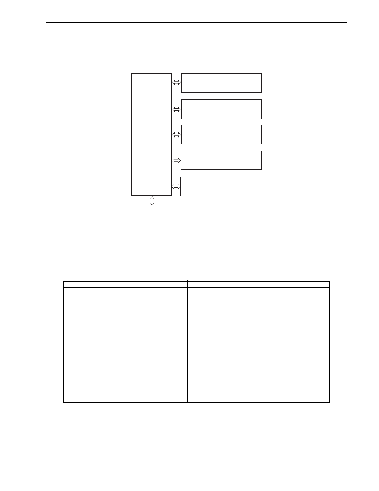
2.1.1 Outline
0018-3088
LBP3370 / LBP3310
The machine may be broadly divided into the following 6 functional blocks: engine control system, laser exposure system, image formation system, pickup/trans-
port/delivery system, fixing system, and externals/auxiliary control system.
F-2-1
2.2 Basic Sequense
2.2.1 Basic Operation Sequence
0018-3089
LBP3370 / LBP3310
The operational sequences are controlled by the microprocessor on the engine controller PCB.
The table below describes the purposes of each period, from the power switch is turned ON until the print operation is completed, and the main motor stops. See
the appendix for detailed timing chart.
T-2-1
2.2.2 Power-on sequence
0018-3090
LBP3370 / LBP3310
The sequence from when the power switch is turned ON until it gets the STBY status is described in the following.
1) Power ON
2) CPU initialization
3) Video interface communication start
4) Residual paper in the printer check
Check each sensor in the printer for any residual paper
Period Purpose Remarks
WAIT
(WAIT period)
From the power switch is turned ON until the
main motor initial drive is completed.
To clear the potential of drum surface and
to clean the transfer charging roller.
Detect the presence of cartridge.
STBY
(STANDBY)
From the end of the WAIT period or the
LSTR period until the pick-up command is
input from the video controller. Or from the
end of the LSTR period until the power
switch is turned OFF.
To keep the printer ready to print.
INTR
(INITIAL ROTATION
period)
From the print command is input from the
video controller until the pick-up solenoid is
turned ON.
To stabilize the photosensitive drum
sensitivity for preparation of printing.
PRINT
(Print)
From the end of the INTR period until the
primary high-voltage is turned OFF.
To form the image on the photosensitive
drum according to the VIDEO signals (/
VD01, VD01, /VD02, VD02) input from
the video controller and transfer the toner
image onto the print paper.
LSTR
(LAST ROTATION period)
From the primary high-voltage is turned OFF
until the main motor stops.
To deliver the last print paper completely
out and clean the transfer charging roller.
When the pick-up command is input from
the video controller, the INTR period
starts right after the LSTR period is
completed.
To external device
Engine control
system
Laser exposure system
Pickup/transport/delivery system
Image formation system
Fixing system
Externals and control system
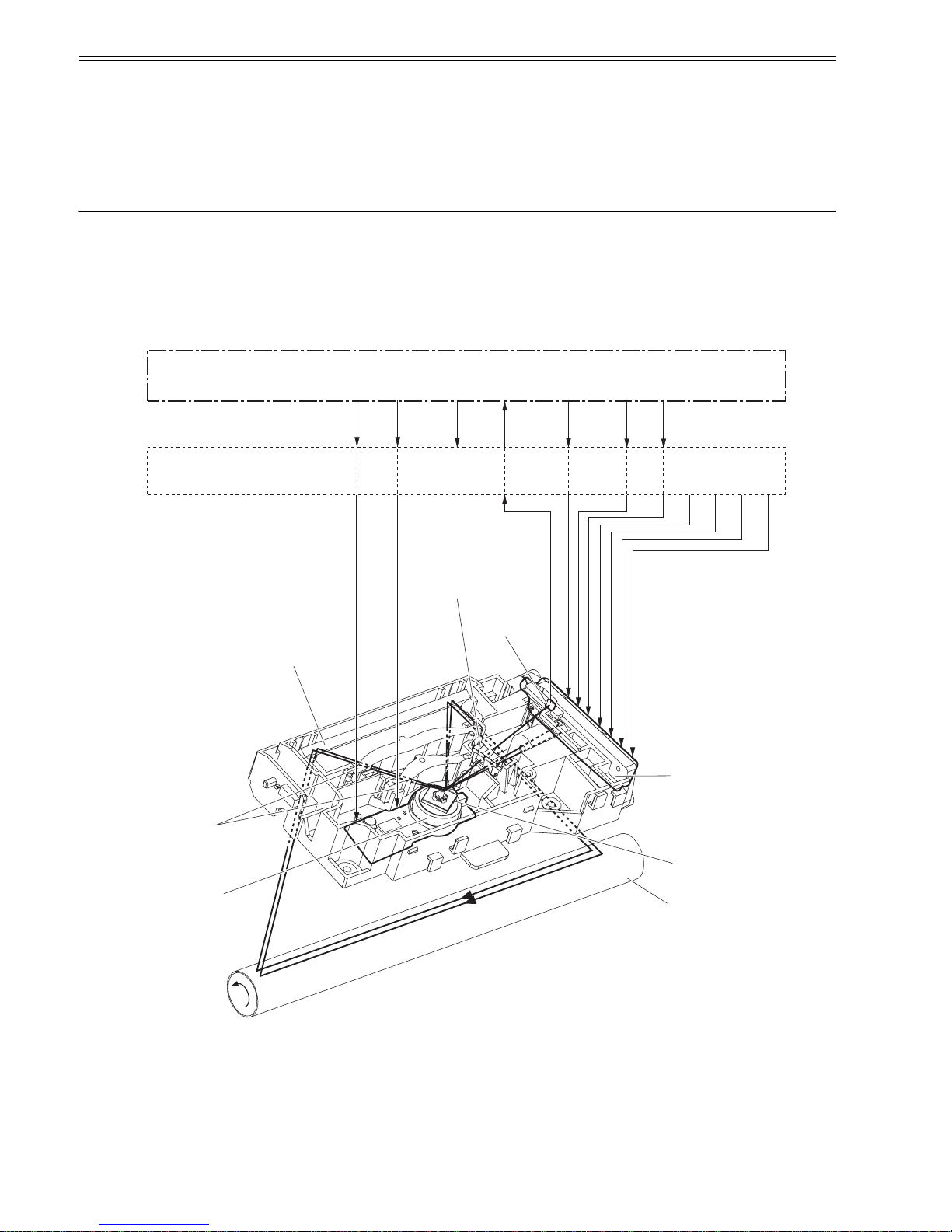
Chapter 2
2-2
5) Main motor initial drive
6) Fixing heater initial drive
Drive the fixing heater to reach the targeted temperature of 100 deg C
7) Scanner motor initial drive
8) High-voltage control
Detect the presence of cartridge and clean the transfer charging roller after the primary charging AC bias is turned ON
9) Failure/Abnormality check
Detect the scanner failure, the fixing unit failure, and the door open during this period
10) Memory tag communication
2.3 LASER EXPOSURE SYSTEM
2.3.1 Overview/Configuration
2.3.1.1 Outline
0018-3093
LBP3370 / LBP3310
The laser/scanner system consists of the laser driver and the scanner motor etc. It is controlled by the signals sent from the engine controller and the video controller.
The laser driver allows the laser diode to emit light according to the LASER CONTROL signals (CNT0, CNT1, CNT2) from the engine controller or the VIDEO
signals (/VDO1, /VDO2, VDO1, VDO2) from the video controller.
F-2-2
The laser/scanner unit of this printer utilizes a "twin beam method" (see Note). It scans two lines simultaneously with 2 laser diodes in order to realize a high-speed
laser scanning.
The operational sequence of the laser/scanner unit is described below.
1) When the video controller sends a print command, the engine controller rotates the scanner motor in order to rotate the four-sided mirror.
2) When the scanner motor starts to rotate, the engine controller forces the laser to emit light with the LASER CONTROL signal and then it starts to control the
scanner motor rotation.
3) The engine controller controls the scanner motor to rotate at a constant speed with the SCANNER MOTOR SPEED CONTROL signal.
4) The video controller sends the VIDEO signals to the laser driver PCB after the scanner motor rotation reaches its targeted speed.
5) The laser driver allows two laser diodes to emit light according to these signals.
Photsensitive drum
BD sensor
Mirror
Four-sided mirror
Laser driver PCB
Cylindrical lens
Focusing lens
Scanner motor
Video controller PCB
Engine controller PCB
/BDO /BDI CNT0 CNT1
VDO1
/VDO1
VDO2
/VDO2
CNT2
/ACC /DEC
 Loading...