

Canon LBP3310 Service Manual

Service Manual
LBP3310/3370 Series
Jan 25 2008

Application
This manual has been issued by Canon Inc. for qualified persons to learn technical theory, insta llati on, ma intenance, and repair
of products. This manual covers all localities where the products are sold. For this reason, there may be information in this
manual that does not apply to your locality.
Corrections
This manual may contain technical inaccuracies or typographical errors due to improvements or changes in products. When
changes occur in applicable products or in the contents of this manual, Canon will release technical information as the need
arises. In the event of major changes in the contents of this manual over a long or short period, Canon will issue a new edition
of this manual.
The following paragraph does not apply to any countries where such provisions are inconsistent with local law.
Trademarks
The product names and company names used in this manual are the registered trademarks of the individual companies.
Copyright
This manual is copyrighted with all rights reserved. Under the copyright laws, this manual may not be copied, reproduced or
translated into another language, in whole or in part, without the written consent of Canon Inc.
COPYRIGHT © 2001 CANON INC.
Printed in Japan
Caution
Use of this manual should be strictly supervised to avoid disclosure of confidential information.

Symbols Used
This documentation uses the following symbols to indicate special information:
Symbol Description
Indicates an item of a non-specific nature, possibly classified as Note, Caution, or Warning.
Indicates an item requiring care to avoid electric shocks.
Indicates an item requiring care to avoid combustion (fire).
Indicates an item prohibiting disassembly to avoid electric shocks or problems.
Indicates an item requiring disconnection of the power plug from the electric outlet.
Indicates an item intended to provide notes assisting the understanding of the topic in question.
Memo
Introduction
REF.
Indicates an item of reference assisting the understanding of the topic in question.
Provides a description of a service mode.
Provides a description of the nature of an error indication.

Introduction
The following rules apply throughout this Service Manual:
1. Each chapter contains sections explaining the purpose of specific functions and the relationship between electrical and mechanical systems with reference to the timing of operation.
In the diagrams, represents the path of mechanical drive; where a signal name accompanies the symbol , the arrow indicates the
direction of the electric signal.
The expression "turn on the power" means flipping on the power switch, closing the front door, and closing the delivery unit door, which results in
supplying the machine with power.
2. In the digital circuits, '1'is used to indicate that the voltage level of a given signal is "High", while '0' is used to indicate "Low".(The voltage value, however, differs from circuit to circuit.) In addition, the asterisk (*) as in "DRMD*" indicates that the DRMD signal goes on when '0'.
In practically all cases, the internal mechanisms of a microprocessor cannot be checked in the fi eld. Ther efore, the operations of the microprocessors
used in the machines are not discussed: they are explained in terms of fro m sensors to the input of the DC controller PCB and from the output of the
DC controller PCB to the loads.
The descriptions in this Service Manual are subject to change without notice for product improvement or other purposes, and major changes will be communicated in the form of Service Information bulletins.
All service persons are expected to have a good understanding of the contents of this Service Manual and all relevant Service Information bulletins and be
able to identify and isolate faults in the machine."

Contents
Contents
Chapter 1 PRODUCT DESCRIPTION
1.1 Features .....................................................................................................................................................1- 1
1.1.1 Feature....................................................................................................................................................................1- 1
1.2 System Construction ..................................................................................................................................1- 1
1.2.1 System Construction ......................................................... ......................................................................................1- 1
1.2.2 System Construction ......................................................... ......................................................................................1- 1
1.3 Product Specifications................................................................................................................................1- 1
1.3.1 Product Specifications.............................................................................................................................................1- 1
1.3.2 Product Specifications.............................................................................................................................................1- 2
1.4 Name of Parts.............................................................................................................................................1- 3
1.4.1 External View............................................ ................................................... ....................................... .....................1- 3
1.4.2 External View............................................ ................................................... ....................................... .....................1- 4
1.4.3 Cross Sectional Views.............................................................................................................................................1- 5
1.5 Using the Machine......................................................................................................................................1- 6
1.5.1 Control Panel........................................................................................................................... .. ..............................1- 6
1.5.2 Control Panel........................................................................................................................... .. ..............................1- 6
Chapter 2 TECHNICAL REFERENCE
2.1 Functional Configuration........ .......................................... ... ... .......................................... .... .......................2- 1
2.1.1 Outline.....................................................................................................................................................................2- 1
2.2 Basic Sequense..........................................................................................................................................2- 1
2.2.1 Basic Operation Sequence............................................................................................................................... .......2- 1
2.2.2 Power-on sequence.................................................................................................................................... .............2- 1
2.3 LASER EXPOSURE SYSTEM...................................................................................................................2- 2
2.3.1 Overview/Configuration................................................................................................................ ...........................2- 2
2.3.1.1 Outline...................................................................................................................................................................................... 2- 2
2.3.1.2 Laser Control Circuit ................................................................................................................................................................ 2- 3
2.3.2 Controlling the Laser Activation Timing............................................................................................................ ... ....2- 5
2.3.2.1 Laser emission control.............................................................................................................................................................2- 5
2.3.2.2 Horizontal synchronous control................................................................................................................................................ 2- 5
2.3.3 Laser Control...........................................................................................................................................................2- 5
2.3.3.1 Automatic power control (APC)................................................................................................................................................2- 5
2.3.3.2 Image masking control............................................................................................................................................................. 2- 5
2.3.4 Laser Scanner Motor Control ..................................................................................................................................2- 6
2.3.4.1 Outline...................................................................................................................................................................................... 2- 6
2.3.4.2 Scanner motor speed control................................................................................................................................................... 2- 7
2.3.4.3 Scanner motor failure detection...............................................................................................................................................2- 7
2.4 IMAGE FORMATION SYSTEM..................................................................................................................2- 7
2.4.1 Overview/Configuration................................................................................................................ ...........................2- 7
2.4.1.1 Outline...................................................................................................................................................................................... 2- 7
2.4.1.2 Print Process............................................................................................................................................................................ 2- 8
2.4.1.3 Electrostatic latent image formation block ............................................................................................................................... 2- 9
2.4.1.4 Development block ...................... ..................... ..................... ..................... ............................................................................. 2- 9
2.4.1.5 Transfer block ........................................................................................................................................................................ 2- 10
2.4.1.6 Fixing block............................................................................................................................................................................2- 11
2.4.1.7 Photosensitive drum cleaning block ....................................................................................................................................... 2- 11
2.4.2 High-Voltage Control.............................................................................................................................................2- 12
2.4.2.1 Outline.................................................................................................................................................................................... 2- 12
2.4.2.2 Primary charging bias generation .......................................................................................................................................... 2- 12
2.4.2.3 Developing bias generation ................................................................................................................................................... 2- 12
2.4.2.4 Transfer charging bias generation ......................................................................................................................................... 2- 13

Contents
2.4.2.5 Fixing bias generation............................................................................................................................................................ 2- 13
2.4.2.6 Cartridge presence detection.................................................................................................................................................2- 13
2.5 PICKUP AND FEEDING SYSTEM...........................................................................................................2- 13
2.5.1 Overview/Configuration..........................................................................................................................................2- 13
2.5.1.1 Outline.................................................................................................................................................................................... 2- 13
2.5.2 Detecting Jams......................................................................................................................................................2- 14
2.5.2.1 Jam Detection Outline............................................................................................................................................................ 2- 14
2.5.2.2 Delay Jams ............................................................................................................................................................................ 2- 15
2.5.2.3 Stationary Jams ..................................................................................................................................................................... 2- 15
2.5.2.4 Other Jams ............................................................................................................................................................................ 2- 15
2.5.3 Cassette Pickup.....................................................................................................................................................2- 15
2.5.3.1 Cassette pick-up .................................................................................................................................................................... 2- 15
2.5.4 Multi-purpose Pickup .............................................................................................................................................2- 16
2.5.4.1 Manual Fees pick-ip...............................................................................................................................................................2- 16
2.5.5 Duplex Feeding ......................................................................................................................................................2- 16
2.5.5.1 Outline.................................................................................................................................................................................... 2- 16
2.5.5.2 Operation ............................................................................................................................................................................... 2- 16
2.6 EXTERNAL AND CONTROLS SYSTEM .................................................................................................2- 17
2.6.1 Fan.........................................................................................................................................................................2- 17
2.6.1.1 Fan motor control...................................................................................................................................................................2- 17
2.6.2 Power Supply............................................................................................................ ... ..........................................2- 17
2.6.2.1 Power Supply......................................................................................................................................................................... 2- 17
2.6.2.2 Protective Functions .............................................................................................................................................................. 2- 18
2.7 ENGINE CONTROL SYSTEM ....................................................... ... ... ... .... ... ... ... ... .................................2- 19
2.7.1 Video Controller.....................................................................................................................................................2- 19
2.7.1.1 Outline.................................................................................................................................................................................... 2- 19
2.7.1.2 Outline of Operation by Block ................................................................................................................................................ 2- 19
2.7.1.3 Overview................................................................................................................................................................................2- 20
2.7.1.4 Outline of Operation by Block ................................................................................................................................................ 2- 20
2.7.2 Engine Controller.................................................................... ...............................................................................2- 21
2.7.2.1 Outline.................................................................................................................................................................................... 2- 21
2.8 FIXING UNIT/DELIVERY SYSTEM..........................................................................................................2- 23
2.8.1 Overview/Configuration..........................................................................................................................................2- 23
2.8.1.1 Outline.................................................................................................................................................................................... 2- 23
2.8.2 Various Control Mechanisms.................................................................................................................................2- 24
2.8.2.1 Fixing Temperature Control ................................................................................................................................................... 2- 24
2.8.2.2 Protective Functions .............................................................................................................................................................. 2- 25
Chapter 3 DISASSEMBLY AND ASSEMBLY
3.1 EXTERNAL AND CONTROLS SYSTEM ...................................................................................................3- 1
3.1.1 Rear Cover...............................................................................................................................................................3- 1
3.1.1.1 Preparation for removing the rear cover unit ........................................................................................................................... 3- 1
3.1.1.2 Removing the rear cover unit................................................................................................................................................... 3- 1
3.1.2 Right Cover..................................................................................................................................... .........................3- 1
3.1.2.1 Detaching the right cover......................................................................................................................................................... 3- 1
3.1.3 Left Cover ................................................................................................................................................................3- 2
3.1.3.1 Detaching the left cover ........................................................................................................................................................... 3- 2
3.1.4 Upper Cover......................................................................................................................... ....................................3- 3
3.1.4.1 Preparation for detaching the upper cover unit........................................................................................................................ 3- 3
3.1.4.2 Detaching the upper cover.......................................................................................................................................................3- 3
3.1.4.3 Detaching the upper cover.......................................................................................................................................................3- 3
3.1.5 Front Cover..................................................................................................................................... .........................3- 4
3.1.5.1 Preparation for detaching the front cover unit.......................................................................................................................... 3- 4
3.1.5.2 Detaching the front cover unit.................................................................................................................................................. 3- 4
3.1.6 Main Drive Unit ........................................................................................................................................... .............3- 5
3.1.6.1 Preparation for removing the main drive assembly..................................................................................................................3- 5
3.1.6.2 Removing the main drive assembly.........................................................................................................................................3- 5
3.1.7 Duplexing Drive Unit................................................................................................................................................3- 6

Contents
3.1.7.1 Removing the duplexing drive assembly .................................................................................................................................3- 6
3.1.8 Operation Panel Unit ....................................................................................................................... ........................3- 7
3.1.8.1 Preparation for detaching the control panel.............................................................................................................................3- 7
3.1.8.2 Detaching the control panel ..................................................................................................................................................... 3- 7
3.1.8.3 Detaching the control panel ..................................................................................................................................................... 3- 7
3.1.9 Engine controller board ........................................................... ................................................................................3- 8
3.1.9.1 Preparation for removing the engine controller PCB ...............................................................................................................3- 8
3.1.9.2 Removing the engine controller PCB.......................................................................................................................................3- 8
3.1.10 Duplexing Driver Board...................................................................................................................................... ....3- 9
3.1.10.1 Preparation for removing the duplexing driver PCB...............................................................................................................3- 9
3.1.10.2 Removing the duplexing driver PCB .................................................................................................................................... 3- 10
3.1.11 Video Controller Board ........................................................................................................................................3- 10
3.1.11.1 Removing the video controller PCB ..................................................................................................................................... 3- 10
3.1.11.2 Removing the video controller PCB ..................................................................................................................................... 3- 10
3.1.12 USB Board...........................................................................................................................................................3- 11
3.1.12.1 Removing the USB PCB ...................................................................................................................................................... 3- 11
3.1.13 Door Switch ....................................................... ... ................................................... ............................................3- 12
3.1.13.1 Removing the door switch.................................................................................................................................................... 3- 12
3.1.14 Main Body Fan............................................................................................. ... .....................................................3- 12
3.1.14.1 Preparation for removing the fan.......................................................................................................................................... 3- 12
3.1.14.2 Removing the fan.................................................................................................................................................................3- 12
3.2 LASER EXPOSURE SYSTEM.................................................................................................................3- 13
3.2.1 Laser Scanner Unit................................................................................................................................................3- 13
3.2.1.1 Preparation for removing the laser scanner unit....................................................................................................................3- 13
3.2.1.2 Removing the laser scanner unit ...........................................................................................................................................3- 13
3.3 IMAGE FORMATION SYSTEM................................................................................................................3- 13
3.3.1 Transfer Charging Roller.......................................................................................................................................3- 13
3.3.1.1 Removing the transfer charging roller....................................................................................................................................3- 13
3.4 PICKUP AND FEEDING SYSTEM...........................................................................................................3- 13
3.4.1 Cassette Pickup Roller..........................................................................................................................................3- 13
3.4.1.1 Removing the cassette pickup roller......................................................................................................................................3- 13
3.4.2 Cassette Pickup solenoid......................................................................................................................................3- 14
3.4.2.1 Preparation for removing the cassette pickup solenoid ......................................................................................................... 3- 14
3.4.2.2 Removing the cassette pickup solenoid................................................................................................................................. 3- 14
3.4.3 Cassette Separation Pad.......................................................................................................................................3- 14
3.4.3.1 Removing the cassette separation pad.................................................................................................................................. 3- 14
3.4.4 Manual Pickup Roller.............................................................................................. ... ............................................3- 14
3.4.4.1 Removing the manual pickup roller........................................................................................................................................ 3- 14
3.4.5 Manual Separation Pad.........................................................................................................................................3- 15
3.4.5.1 Preparation for removing the manual separation pad............................................................................................................3- 15
3.4.5.2 Removing the manual separation pad ................................................................................................................................... 3- 15
3.4.6 Registration Roller.................................................................................................................................................3- 15
3.4.6.1 Preparation for removing the registration roller...................................................................................................................... 3- 15
3.4.6.2 Removing the registration roller.............................................................................................................................................3- 15
3.4.7 Main Motor.............................................................................................................................................................3- 16
3.4.7.1 Preparation for removing the main motor .............................................................................................................................. 3- 16
3.4.7.2 Removing the main motor......................................................................................................................................................3- 16
3.4.8 Reversal Solenoid .................................................................................................................................................3- 16
3.4.8.1 Preparation for removing the reverse solenoid......................................................................................................................3- 16
3.4.8.2 Removing the reverse solenoid .............................................................................................................................................3- 16
3.4.9 Duplexing Unit.......................................................................................................................................................3- 16
3.4.9.1 Preparation for removing the duplexing unit .......................................................................................................................... 3- 16
3.4.9.2 Removing the duplexing unit.................................................................................................................................................. 3- 16
3.5 FIXING SYSTEM......................................................................................................................................3- 17
3.5.1 Fixing Unit.............................................................................................. ................................................................3- 17
3.5.1.1 Preparation for removing the fixing assembly........................................................................................................................ 3- 17
3.5.1.2 Removing the fixing assembly ............................................................................................................................................... 3- 17
3.5.1.3 Removing the fixing assembly ............................................................................................................................................... 3- 18
3.5.2 Fixing Film Unit......................................................................................................................................................3- 19

Contents
3.5.2.1 Preparation for removing the fixing film unit........................................................................................................................... 3- 19
3.5.2.2 Removing the fixing film unit..................................................................................................................................................3- 19
3.5.3 Fixing Pressure Roller................................................................................. ... ... .....................................................3- 20
3.5.3.1 Preparation for removing the fixing pressure roller................................................................................................................3- 20
3.5.3.2 Removing the fixing pressure roller .......................................................................................................................................3- 20
Chapter 4 MAINTENANCE AND INSPECTION
4.1 Periodically Replaced Parts ....................................... ... .... ... ... ... .... ... ... ... ...................................................4- 1
4.1.1 Periodically Replaced Parts.....................................................................................................................................4- 1
4.2 Consumables .............................................................................................................................................4- 1
4.2.1 Life Expectancy of Consumable Parts.....................................................................................................................4- 1
4.3 Periodical Service.......................................................................................................................................4- 1
4.3.1 Periodic Service.......................................................................................................................................................4- 1
4.4 Cleaning .....................................................................................................................................................4- 1
4.4.1 Cleaning During Service Visit ..................................................................................................................................4- 1
Chapter 5 TROUBLESHOOTING
5.1 MEASUREMENT AND ADJUSTMENT......................... .... .........................................................................5- 1
5.1.1 Test Print..................................................................................................................................................................5- 1
5.1.1.1 Test Print.................................................................................................................................................................................. 5- 1
5.1.1.2 Test Print.................................................................................................................................................................................. 5- 1
5.1.2 Mechanical Adjustment............................................................................................................................................5- 1
5.1.2.1 Checking the Nip Width (fixing pressure roller)........................................................................................................................ 5- 1
5.2 SERVICE TOOLS ......................................................................................................................................5- 2
5.2.1 Standard Tools........................................................................................................................ .................................5- 2
5.2.2 Special Tools ..................................................................................................................................... ... ...................5- 2
5.3 ERROR CODE TABLE .. ... ... .... ... ... ... .... ...................................... .... ... ... ... .... ... ... ... ......................................5- 2
5.3.1 Error Code ......................................................................................................................................... ......................5- 2
5.3.2 Error Code ......................................................................................................................................... ......................5- 3
5.3.3 A4-XX_ERROR........................................................................................................................................................5- 4
5.3.4 A5-XX_ERROR........................................................................................................................................................5- 4
5.3.5 A7-XX_ERROR........................................................................................................................................................5- 4
5.3.6 D7-XX_ERROR .......................................................................................................................................................5- 4
5.3.7 D8-XX_ERROR .......................................................................................................................................................5- 4
5.4 Version Up..... ... ... .... ... ... ... ... ....................................... ... .... ... ... ... ................................................................5- 5
5.4.1 Overview of Upgrading Work...................................................................................................................................5- 5
5.4.2 Construction of Firmware.........................................................................................................................................5- 5
5.4.3 Outline of the Service Support Tool.........................................................................................................................5- 5
5.4.4 Registering the Firmware........................................................................................................................................5- 7
5.4.5 Making Connections ........................................................................................................................................ ........5- 9
5.4.6 The down load procedure of the system................................................................................................................5- 10
5.5 Service Mode ...........................................................................................................................................5- 13
5.5.1 PCL........................................................................................................................................................................5- 13
5.5.1.1 Overview................................................................................................................................................................................5- 13
5.5.1.2 Service Mode.........................................................................................................................................................................5- 13
Chapter 6 APPENDIX
6.1 OUTLINE OF ELECTRICAL COMPONENTS............................................................................................6- 1
6.1.1 Clutch/Solenoid........................................................................................................................................................6- 1
6.1.1.1 Solenoid...................................................................................................................................................................................6- 1
6.1.2 Motor........................................................................................................................................................................6- 1
6.1.2.1 Motor........................................................................................................................................................................................ 6- 1
6.1.3 Fan.......................................................................................................................................... ... ..............................6- 2
6.1.3.1 Fan........................................................................................................................................................................................... 6- 2

Contents
6.1.4 Sensor.....................................................................................................................................................................6- 2
6.1.4.1 Sensor...................................................................................................................................................................................... 6- 2
6.1.5 PCBs ............................................................................................................................................... ........................6- 3
6.1.5.1 PCB.......................................................................................................................................................................................... 6- 3

Chapter 1 PRODUCT DESCRIPTION

Contents
Contents
1.1 Features..........................................................................................................................................................................1-1
1.1.1 Feature.......................................................................................................................................................................................... 1-1
1.2 System Construction......................................................................................................................................................1-1
1.2.1 System Construction .................................................................................................................................................................... 1-1
1.2.2 System Construction .................................................................................................................................................................... 1-1
1.3 Product Specifications....................................................................................................................................................1-1
1.3.1 Product Specifications ................................................................................................................................................................. 1-1
1.3.2 Product Specifications ................................................................................................................................................................. 1-2
1.4 Name of Parts.................................................................................................................................................................1-3
1.4.1 External View .............................................................................................................................................................................. 1-3
1.4.2 External View .............................................................................................................................................................................. 1-4
1.4.3 Cross Sectional Views ................................................................................................................................................................. 1-5
1.5 Using the Machine.........................................................................................................................................................1-6
1.5.1 Control Panel ............................................................................................................................................................................... 1-6
1.5.2 Control Panel ............................................................................................................................................................................... 1-6
1.1 Features
Chapter 1
1.1.1 Feature
LBP3370 / LBP3310
1. Compact, high-speed and high-resolution printer
Regardless of its compact size that enables an installation on side of desks, this printer realizes the printing speed of 21 pages per minute in letter-size paper with
the resolution of 600 dpi.
2. Short wait time and low power consumption
The printer utilizes the on-demand fixing method that turns on the heater only during print operations. This shortens wait time, and enables low power
consumption during stand by period.
3. Automatic duplex printing
The printer enables an automatic duplex printing by installing the duplexing unit as a standard equipment in the printer.
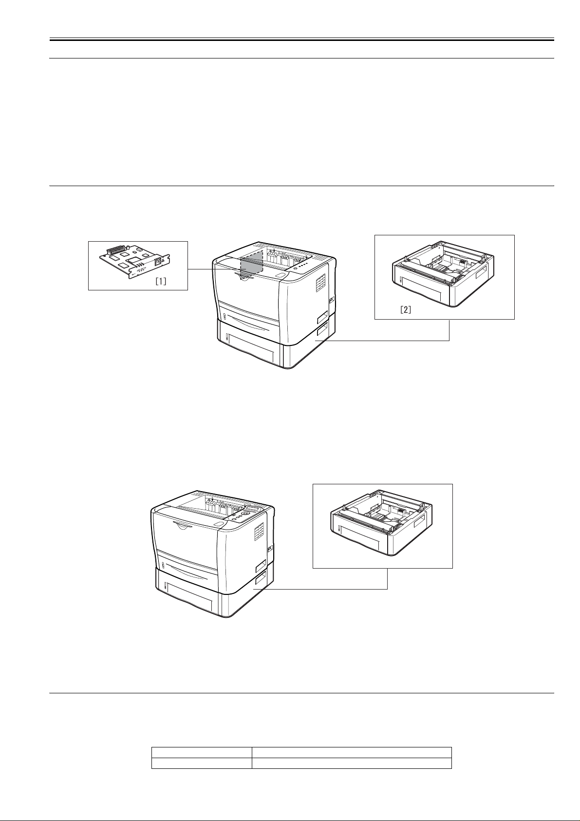
1.2 System Construction
1.2.1 System Construction
LBP3310
0018-3077
0018-3078
1.2.2 System Construction
LBP3370
F-1-1
T-1-1
[1] Network Board NB-C2
[2] Paper Feeder PF-35P
0018-3079
[1]
F-1-2
T-1-2
[1] Paper Feeder PF-35P
1.3 Product Specifications
1.3.1 Product Specifications
LBP3310
Body installation method desktop page printer
Photosensitive medium OPC drum
0018-3080
1-1

Chapter 1
Exposure method semiconductor laser
Development method Toner projection development
Transfer method by roller
Separation method by curvature
Cassette pickup method by pad
Multifeeder pickup method by pad
Drum cleaning method by blade
Fixing method on-demand
Delivery method face-down/face-up
Toner supply type by toner cartridge
Warm-up time in standby: 0 sec (at power-on: 8 sec or less)
Print area top: 5 mm; bottom: 5 mm; left/right: 5 mm (if envelope, top, bottom, left,
Printing resolution 600dpi
First print time 6.5 sec or less (approx.; A4)
Print speed (A4) 26 pages/min (approx.)
Cassette paper size Standard sizes
3k cartridge: about 3000 prints
7k cartridge: about 7000 prints
(A4, single-sided; at 5% image ratio)
right: 10 mm)
A4, B5, A5, Legal, Letter, Executive
Custom sizes
Width 148.0 to 215.9 mm; Length 210.0 to 355.6 mm
Multi-purpose paper size A4, B5, A5, Legal, Letter, Executive, Envelope DL, Envelope COM10,
Cassette paper type plain paper (64 to 90 g/m2), heavy paper (91 to 120 g/m2), recycled
Multi-purpose paper type plain paper (64 to 90 g/m2), heavy paper (91 to 163 g/m2), recycled
Cassette capacity 250 sheets (approx.; plain paper, 64 g/m2)
Multi-purpose capacity 50 sheets (approx.; plain paper, 64 g/m2)
Delivery tray stack Face-down output tray: approx. 125 sheets (64 g/m2)
Duplex method Auto duplexing
Interface Standard : USB2.0, Option : 10Base-T/100Base-TX
Memory 8 MB (internal; no optional memory available)
Hard disk standard : none, option : none
Operating environment
(Temperature range)
Operating environment
(Humidity range)
Noise 55 dB or less (during printing; based on ISO9296; announced noise
Power supply rating AC120V±10% (50/60Hz ±2Hz)
Power consumption (Maximum) 120V: 845W or less
Power consumption 120V
Dimensions 399.7 (W) x 378.6 (D) x 258 (H)mm
Weight printer: Approx;11.2kg (excluding the toner cartridge); toner cartridge:
Envelope C5, Envelope Monarch, Index Card, Custom Paper Size (width
76.2 to 215.9 mm, length 127.0 to 355.6 mm)
paper,
paper, transparency, label paper, envelop (DL, COM10, C5, Monarch,
B5)
Face-up output slot: 1 sheet
10 to 32.5 deg C
20% to 80% RH
emission)
AC230V±10% (50/60Hz ±2Hz)
230V: 909W or less
(approx.; 20 deg C; for input of rated power supply; including peak value
lasting 1 sec or more)
Average suring operation: approx. 386W
Average suring standby: approx. 4W
230V
Average suring operation: approx. 382W
Average suring standby: approx. 4W
Approx,0.8kg(3K cartridge), Approx,1.0kg(7K cartridge)
Option paper feeder
1.3.2 Product Specifications
LBP3370
Body installation method desktop page printer
Photosensitive medium OPC drum
Exposure method semiconductor laser
Development method Toner projection development
1-2
0018-3219

Transfer method by roller
Separation method by curvature
Cassette pickup method by pad
Multifeeder pickup method by pad
Drum cleaning method by blade
Fixing method on-demand
Delivery method face-down/face-up
Toner supply type by toner cartridge
Warm-up time in standby: 0 sec (at power-on: 9 sec or less)
Print area top: 5 mm; bottom: 5 mm; left/right: 5 mm (if envelope, top, bottom, left,
Printing resolution 600dpi
First print time 6.5 sec or less (approx.; A4)
Print speed (A4) 26 pages/min (approx.)
Cassette paper size Standard sizes
Multi-purpose paper size Standard sizes
Cassette paper type plain paper (64 to 90 g/m2), heavy paper (91 to 120 g/m2), recycled
Multi-purpose paper type plain paper (64 to 90 g/m2), heavy paper (91 to 163 g/m2), recycled
Cassette capacity 250 sheets (approx.; plain paper, 64 g/m2)
Multi-purpose capacity 50 sheets (approx.; plain paper, 64 g/m2)
Delivery tray stack Face-down output tray: approx. 125 sheets (64 g/m2)
3k cartridge: about 3000 prints
7k cartridge: about 7000 prints
(A4, single-sided; at 5% image ratio)
right: 10 mm)
A4, B5, A5, Legal, Letter, Executive
Custom sizes
Width 148.0 to 215.9 mm; Length 210.0 to 355.6 mm
A4, B5, A5, Legal, Letter, Executive, Envelope DL, Envelope COM10,
Envelope C5, Envelope Monarch, Envelope B5, Index Card, Statement,
16K
Custom sizes
Width 76.2 to 215.9 mm; Length 127.0 to 355.6 mm
paper
paper, transparency, label paper, envelop (DL, COM10, C5, Monarch,
B5)
Face-up output slot: 1 sheet
Chapter 1
1.4 Name of Parts
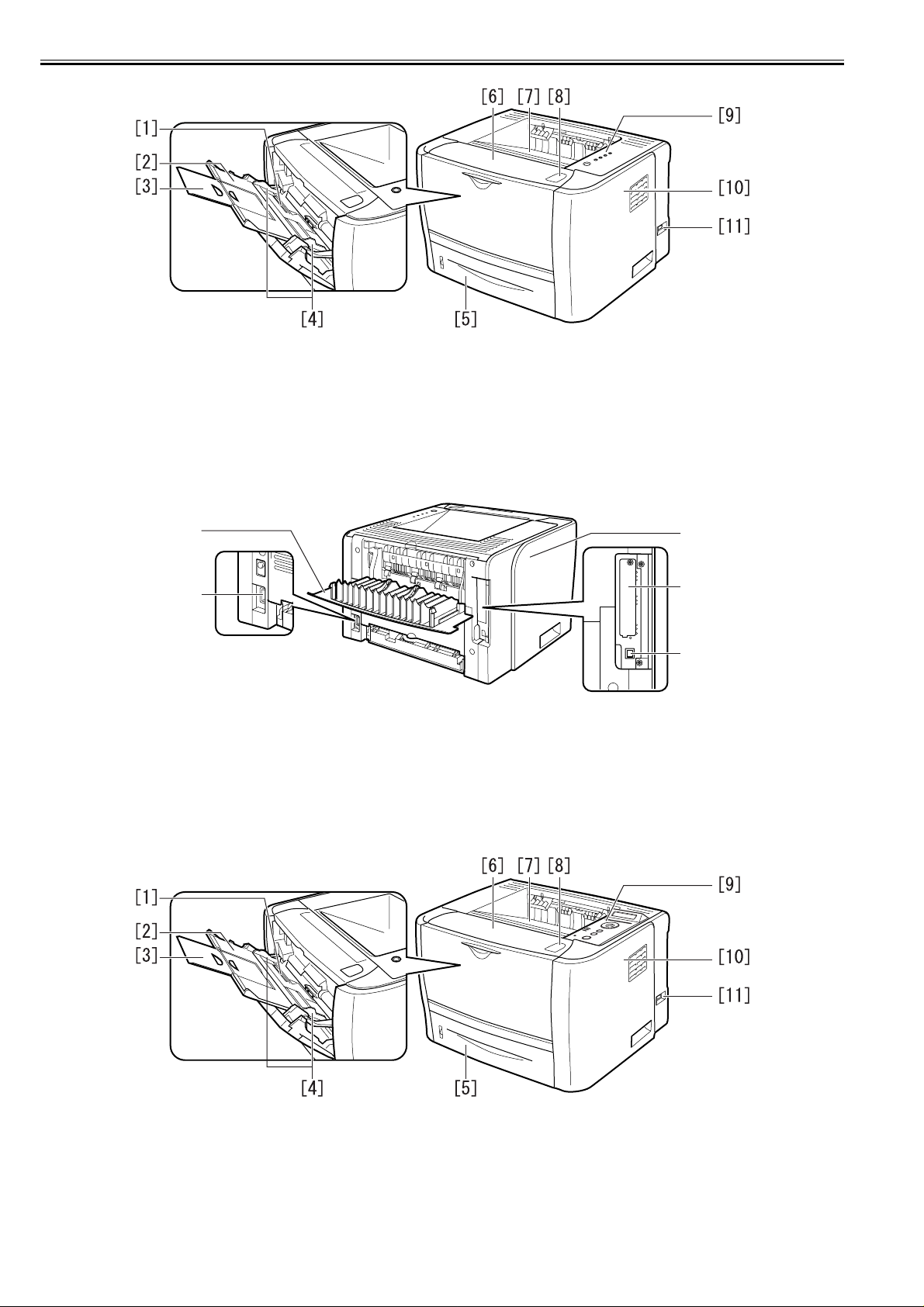
1.4.1 External View
LBP3310
Duplex method Auto duplexing
Interface Standard : USB2.0, 10Base-T/100Base-TX
Memory 8 MB (internal; no optional memory available)
Hard disk standard : none, option : none
Operating environment
(Temperature range)
Operating environment
(Humidity range)
Noise 55 dB or less (during printing; based on ISO9296; announced noise
Power supply rating AC230V±10% (50/60Hz ±2Hz)
Power consumption (Maximum) 950W or less
Power consumption Average suring operation: approx. 403W
Dimensions 399.7 x 378.6 x 267 mm
Weight printer: Approx;11.4kg (excluding the toner cartridge); toner cartridge:
Option paper feeder
10 to 32.5 deg C
20% to 80% RH
emission)
(approx.; 20 deg C)
Average suring standby: approx. 9W
Approx,0.8kg(3K cartridge), Approx,1.0kg(7K cartridge)
0018-3082
1-3
Chapter 1
F-1-3
[1] Manual feeder tray [7] Face-down Output Tray
[2] Sub tray [8] Open Button
[3] Extension tray [9] Control Panel
[4] Paper guide [10] Right cover
[5] Paper Cassette [11] Power Switch
[6] Front Cover
1.4.2 External View
LBP3370
[1]
[2]
F-1-4
[1] Face-up Output Tray [4] Expansion Slot
[2] Power Socket [5] USB Connector
[3] Left cover
[3]
[4]
[5]
0018-3084
1-4
F-1-5
[1] Manual feeder tray [7] Face-down Output Tray
[2] Sub tray [8] Open Button
[3] Extension tray [9] Control Panel
[4] Paper guide [10] Right cover
[5] Paper Cassette [11] Power Switch
[6] Front Cover
Chapter 1
[1]
[2]
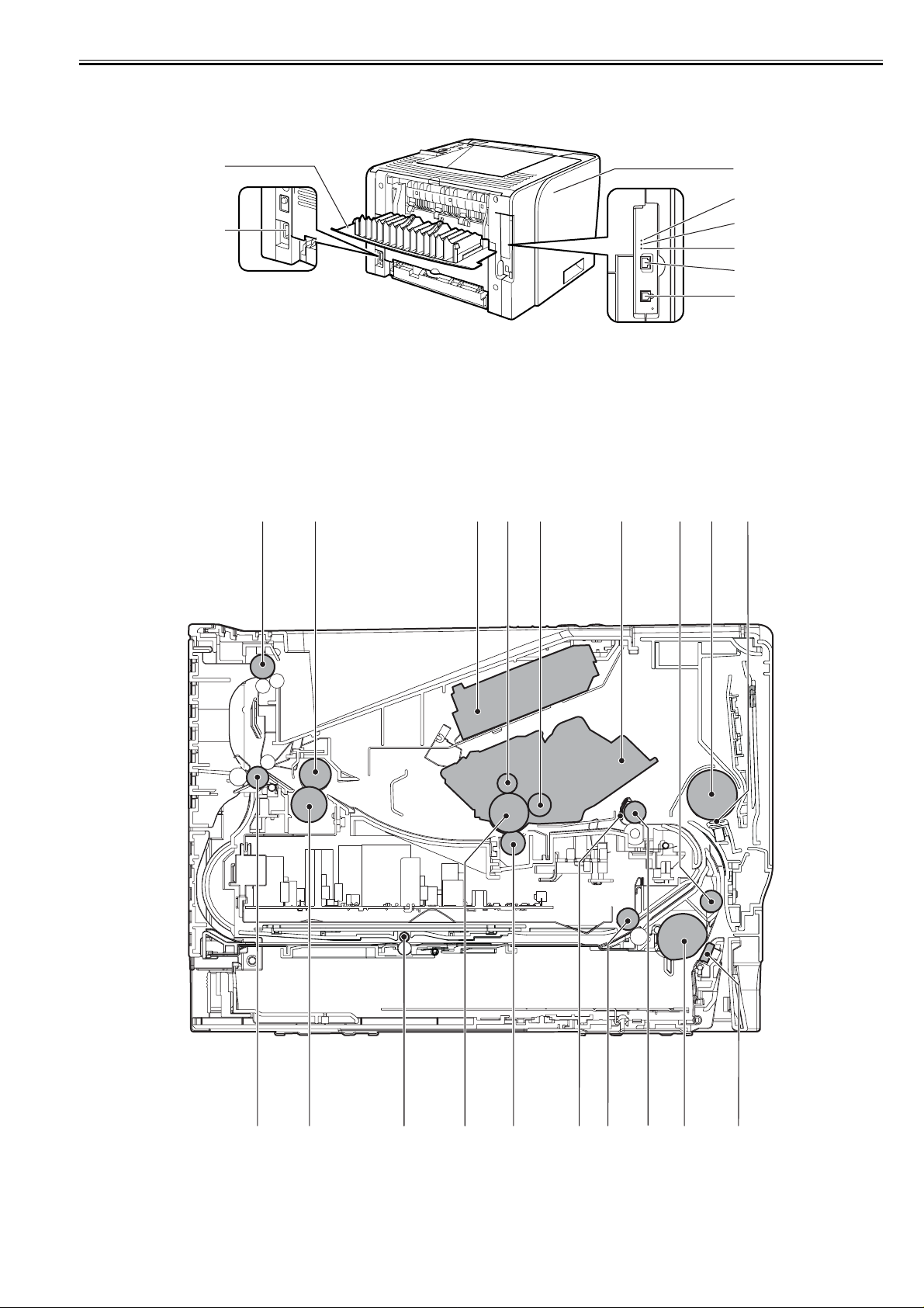
1.4.3 Cross Sectional Views
LBP3370 / LBP3310
F-1-6
[1] Face-up Output Tray [5] 10 Indicatotor
[2] Power Socket [6] TX/RX Indicatotor
[3] Left Cover [7] LAN Connector
[4] 100 Indicatotor [8] USB Connector
[1] [2] [3] [4] [5] [6] [8][7]
[3]
[4]
[5]
[6]
[7]
[8]
0018-3085
[9]
[18][19]
[1] Face-down delivery roller [11] Pick-up roller
[2] Fixing film unit [12] Registration roller
[17] [16] [15] [14] [13] [12] [11] [10]
F-1-7
1-5
Chapter 1
[3] Laser/scanner unit [13] Duplex pick-up roller
[4] Primary charging roller [14] Registration shutter
[5] Developing cylinder [15] Transfer charging roller
[6] Toner cartridge [16] Photosensitive drum
[7] Feed roller [17] Duplex feed roller
[8] Manual pickup roller [18] Pressure roller
[9] Manual separation pad [19] Face-up delivery roller
[10] Separation pad
1.5 Using the Machine
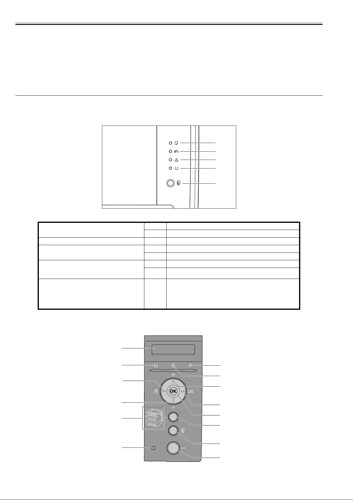
1.5.1 Control Panel
LBP3310
[1] Load Paper Indicator
[2] Paper Jam Indicator
[3] Alarm Indicator
[4]Ready Indicator
[5] Cancel Job Key/Cancel Job Indicator Pressing this key enables the cancellation of the jobs in which an error is
On
Blinking:
Blinking
On
Blinking
On
Blinking
[1]
[2]
[3]
[4]
[5]
F-1-8
There is no paper in any paper source.
No paper or paper of an inappropriate size s loaded
A paper jam is occurring, disabling printing.
Service call is occurring.
An error is occurring, disabling printing.
The printer is ready to print.
The printer is busy performing some kind of processing or operation, such as
printing, warming up, cleaning, or pausing a job.
occurring and those in progress. The indicator comes on while pressing the ke y.
The indicator blinks while a job is in the cancellation process.
0018-3086
1.5.2 Control Panel
LBP3370
1-6
[1]
[14]
[13]
[12]
[11]
[10]
0018-3087
[2]
[3]
[4]
[5]
[6]
[7]
[8]
[9]
F-1-9

Chapter 1
[1] Display
Displays the printer status, messages, the items and setting values of the menu functions.
[2] Job Indicator (Green)
On:
The printer is receiving print data, or any print data remains in the printer memory.
Blinking:
The printer is processing print data.
Off:
There is no print data in the printer memory.
[3] Message Indicator (Orange)
On:
The printer cannot print because a problem has occurred in the printer.
(If the printer has entered Power Save Mode 1 when it is offline, only the Message indicator (orange) and Power indicator (green) are on.)
Off:
The printer is in a normal state.
[4] Job Key
On offline:
Does not function when the printer is offline.
On online:
Displays the JOB menu.
On menu operation:
Goes back to the previous menu (Goes back up the hierarchy).
[5] Settings Key
On offline:
Displays the SETUP menu.
On online:
Displays the SETUP menu. However, the USER MAIN. options cannot be specified when the printer is online.
On menu operation:
(green) are on.)
Displays the next right item in the menu. Increases the setting value.
[6] OK Key
On offline:
Does not function when the printer is offline.
On online:
Does not function when the printer is online.
On menu operation:
Goes to the next menu (Goes down the hierarchy). In a lowest menu level (When a setting value is displayed), determines the setting value.
[7] Feeder Selection Key
On offline:
Displays the SELECT FEEDER menu.
On online:
Displays the SELECT FEEDER menu.
On menu operation:
Does not function.
[8] Cancel Job Key
On offline:
Cancels the job when the Job indicator is on or blinking. Does not function when the Job indicator is off.
On online:
Cancels the job when the Job indicator is on or blinking. Does not function when the Job indicator is off.
[9] Online Key/Online Indicator (Green)
Turns on (online)/off (offline) the connection to the computer.
This key also has the function that, when an error has occurred, releases the printer from the error temporarily and continue s the paused job. However, depending
on the error, you may not be able to cancel it out.
The Online indicator under the Online key indicates the following printer status with its status.
On:
Online (The printer can receive print data from the computer.)
Off:
Offline (The printer cannot receive print data from the computer.)
However, if the printer has entered Power Save Mode, the (Online) indicator is off even when the printer is online.
[10] Power Indicator (Green)
On:
The printer is ON.
Off:
The printer is OFF.
[11]Paper Source Indicators (Green)
On:
The indicator for the currently selected paper source comes on.
Blinking:
There is no paper in the currently selected paper source, or the paper cassette is not set.
Off:
No paper source is selected. No paper cassette including the optional one or paper feeder is set.
[12] Reset Key
On offline:
Displays the RESET menu.
On online:
Displays the RESET menu.
On menu operation:
Goes to the next menu (Goes down the hierarchy).
In a lowest menu level (When a setting value is
displayed), determines the setting value.
[13] Utility Key
On offline:
Does not function when the printer is offline.
On online:
Displays the UTILITY menu.
On menu operation:
Displays the next left item in the menu. Decreases the setting value.
[14] Ready Indicator (Green)
On:
The printer is ready to print. (If the printer has entered Power Save Mode 1 when it is online, only the Ready indicator (green) and Power indicator (green) are on.)
Blinking:
The printer is performing a self-diagnostic test. The printer is in a warm-up state.
1-7

Chapter 1
Off:
The printer cannot print.
1-8

Chapter 2 TECHNICAL REFERENCE

Contents
Contents
2.1 Functional Configuration............................................................................................................................................... 2-1
2.1.1 Outline.......................................................................................................................................................................................... 2-1
2.2 Basic Sequense...............................................................................................................................................................2-1
2.2.1 Basic Operation Sequence ........................................................................................................................................................... 2-1
2.2.2 Power-on sequence ...................................................................................................................................................................... 2-1
2.3 LASER EXPOSURE SYSTEM.....................................................................................................................................2-2
2.3.1 Overview/Configuration .............................................................................................................................................................. 2-2
2.3.1.1 Outline.............................................................................................................................................................................................................2-2
2.3.1.2 Laser Control Circuit.......................................................................................................................................................................................2-3
2.3.2 Controlling the Laser Activation Timing..................................................................................................................................... 2-5
2.3.2.1 Laser emission control ....................................................................................................................................................................................2-5
2.3.2.2 Horizontal synchronous control ................................................................ ... ...................................................................................................2-5
2.3.3 Laser Control ............................................................................................................................................................................... 2-5
2.3.3.1 Automatic power control (APC) .....................................................................................................................................................................2-5
2.3.3.2 Image masking control.. ......................................................................... .........................................................................................................2-5
2.3.4 Laser Scanner Motor Control....................................................................................................................................................... 2-6
2.3.4.1 Outline.............................................................................................................................................................................................................2-6
2.3.4.2 Scanner motor speed control...........................................................................................................................................................................2-7
2.3.4.3 Scanner motor failure detection ......................................................................................................................................................................2-7
2.4 IMAGE FORMATION SYSTEM.................................................................................................................................2-7
2.4.1 Overview/Configuration .............................................................................................................................................................. 2-7
2.4.1.1 Outline.............................................................................................................................................................................................................2-7
2.4.1.2 Print Process....................................................................................................................................................................................................2-8
2.4.1.3 Electrostatic latent image formation block .....................................................................................................................................................2-9
2.4.1.4 Development block .........................................................................................................................................................................................2-9
2.4.1.5 Transfer block ...............................................................................................................................................................................................2-10
2.4.1.6 Fixing block ..................................................................................................................................................................................................2-11
2.4.1.7 Photosensitive drum cleaning block................. ...................................... ... ....................................................................................................2-11
2.4.2 High-Voltage Control ................................................................................................................................................................ 2-12
2.4.2.1 Outline...........................................................................................................................................................................................................2-12
2.4.2.2 Primary charging bias generation..................................................................................................................................................................2-12
2.4.2.3 Developing bias generation........... ... ...................................... ...................................... .................................................................................2-12
2.4.2.4 Transfer charging bias generation.................................................................................................................................................................2-13
2.4.2.5 Fixing bias generation ...................................................................................................................................................................................2-13
2.4.2.6 Cartridge presence detection .........................................................................................................................................................................2-13
2.5 PICKUP AND FEEDING SYSTEM...........................................................................................................................2-13
2.5.1 Overview/Configuration ............................................................................................................................................................ 2-13
2.5.1.1 Outline...........................................................................................................................................................................................................2-13
2.5.2 Detecting Jams........................................................................................................................................................................... 2-14
2.5.2.1 Jam Detection Outline...................................................................................................................................................................................2-14
2.5.2.1.1 Outline................................... ... ...................................... ... .... ................................................................................................................2-14
2.5.2.2 Delay Jams ....................................................................................................................................................................................................2-15
2.5.2.2.1 Pick-up delay jam............................ ... ...................................... ... ..........................................................................................................2-15
2.5.2.2.2 Delivery delay jam ................................................................................................................................................................................2-15
2.5.2.2.3 Reversing delay jam..............................................................................................................................................................................2-15
2.5.2.3 Stationary Jams .............................................................................................................................................................................................2-15
2.5.2.3.1 Pick-up stationary jam .. ...................................... ...................................... ... ..........................................................................................2-15
2.5.2.3.2 Delivery stationary jam .........................................................................................................................................................................2-15
2.5.2.3.3 Reversing stationary jam.......................................................................................................................................................................2-15
2.5.2.4 Other Jams.....................................................................................................................................................................................................2-15
2.5.2.4.1 Wrapping jam.................. ...................................... ... ...................................... .......................................................................................2-15
2.5.2.4.2 Start-up residual jam .......................... ... ...................................... ... ... ....................................................................................................2-15
2.5.2.4.3 Door open jam.......................................................................................................................................................................................2-15

Contents
2.5.3 Cassette Pickup .......................................................................................................................................................................... 2-15
2.5.3.1 Cassette pick-up............................................................................................................................................................................................2-15
2.5.4 Multi-purpose Pickup................................................................................................................................................................. 2-16
2.5.4.1 Manual Fees pick-ip......................................................................................................................................................................................2-16
2.5.5 Duplex Feeding.......................................................................................................................................................................... 2-16
2.5.5.1 Outline ..........................................................................................................................................................................................................2-16
2.5.5.2 Operation ......................................................................................................................................................................................................2-16
2.6 EXTERNAL AND CONTROLS SYSTEM ............................................................................................................... 2-17
2.6.1 Fan.............................................................................................................................................................................................. 2-17
2.6.1.1 Fan motor control..........................................................................................................................................................................................2-17
2.6.2 Power Supply............................................................................................................................................................................. 2-17
2.6.2.1 Power Supply................................................................................................................................................................................................2-17
2.6.2.1.1 Low-voltage Power Supply Circuit ....... ... ...................................... ... ... ................................................................................................ 2-17
2.6.2.2 Protective Functions ..................................................................................................................................................................................... 2-18
2.6.2.2.1 Protective function....................................... ... ...................................... ... ............................................................................................. 2-18
2.7 ENGINE CONTROL SYSTEM .............. ................................................... ................................................................ 2-19
2.7.1 Video Controller ........................................................................................................................................................................ 2-19
2.7.1.1 Outline ..........................................................................................................................................................................................................2-19
2.7.1.2 Outline of Operation by Block......................................................................................................................................................................2-19
2.7.1.3 Overview....................................................................................................................................................................................................... 2-20
2.7.1.4 Outline of Operation by Block......................................................................................................................................................................2-20
2.7.2 Engine Controller....................................................................................................................................................................... 2-21
2.7.2.1 Outline ..........................................................................................................................................................................................................2-21
2.8 FIXING UNIT/DELIVERY SYSTEM....................................................................................................................... 2-23
2.8.1 Overview/Configuration ............................................................................................................................................................ 2-23
2.8.1.1 Outline ..........................................................................................................................................................................................................2-23
2.8.2 Various Control Mechanisms .................................................................................................................................................... 2-24
2.8.2.1 Fixing Temperature Control ......................................................................................................................................................................... 2-24
2.8.2.1.1 Fixing temperature control....................................................................................................................................................................2-24
2.8.2.2 Protective Functions ..................................................................................................................................................................................... 2-25
2.8.2.2.1 Protective function....................................... ... ...................................... ... ............................................................................................. 2-25
2.8.2.2.2 failure detection ........... .... ..................................... .... ...................................... ......................................................................................2-25
2.1 Functional Configuration
Chapter 2
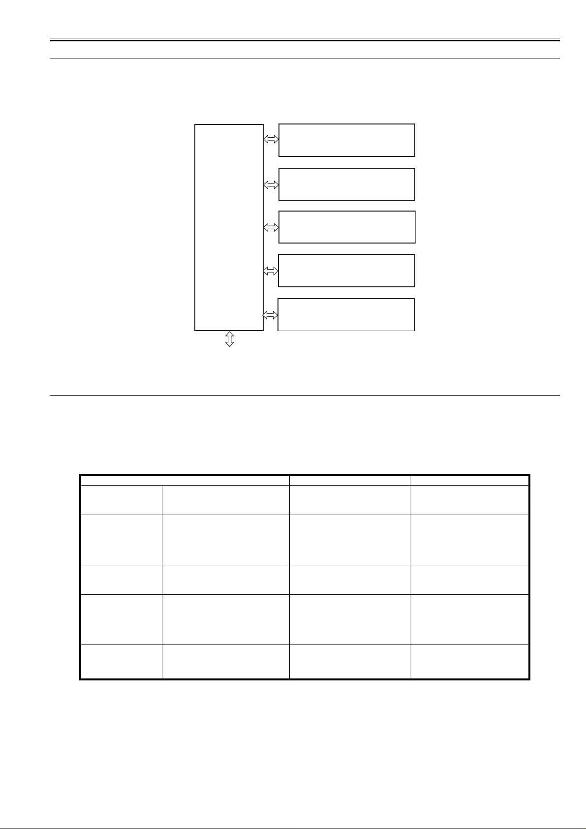
2.1.1 Outline
LBP3370 / LBP3310
0018-3088
The machine may be broadly divided into the following 6 functional blocks: engine control system, laser exposure system, image formation system, pickup/transport/delivery system, fixing system, and externals/auxiliary control system.
Laser exposure system
Image formation system
Engine control
Pickup/transport/delivery system
system
Fixing system
Externals and control system
To external device
F-2-1
2.2 Basic Sequense
2.2.1 Basic Operation Sequence
LBP3370 / LBP3310
The operational sequences are controlled by the microprocessor on the engine controller PCB.
The table below describes the purposes of each period, from the power switch is turned ON until the print operation is completed, and the main motor stops. See
the appendix for detailed timing chart.
WAIT
(WAIT period)
STBY
(STANDBY)
INTR
(INITIAL ROTATION
period)
PRINT
(Print)
LSTR
(LAST ROTATION period)
Period Purpose Remarks
From the power switch is turned ON until the
main motor initial drive is completed.
From the end of the WAIT period or the
LSTR period until the pick-up command is
input from the video controller. Or from the
end of the LSTR period until the power
switch is turned OFF.
From the print command is input from the
video controller until the pick-up solenoid is
turned ON.
From the end of the INTR period until the
primary high-voltage is turned OFF.
From the primary high-voltage is turned OFF
until the main motor stops.
T-2-1
To clear the potential of drum surface and
to clean the transfer charging roller.
To keep the printer ready to print.
To stabilize the photosensitive drum
sensitivity for preparation of printing.
To form the image on the photosensitive
drum according to the VIDEO signals (/
VD01, VD01, /VD02, VD02) input from
the video controller and transfer the toner
image onto the print paper.
To deliver the last print paper completely
out and clean the transfer charging roller.
Detect the presence of cartridge.
When the pick-up command is input from
the video controller, the INTR period
starts right after the LSTR period is
completed.
0018-3089
2.2.2 Power-on sequence
LBP3370 / LBP3310
The sequence from when the power switch is turned ON until it gets the STBY status is described in the following.
1) Power ON
2) CPU initialization
3) Video interface communication start
4) Residual paper in the printer check
Check each sensor in the printer for any residual paper
0018-3090
2-1
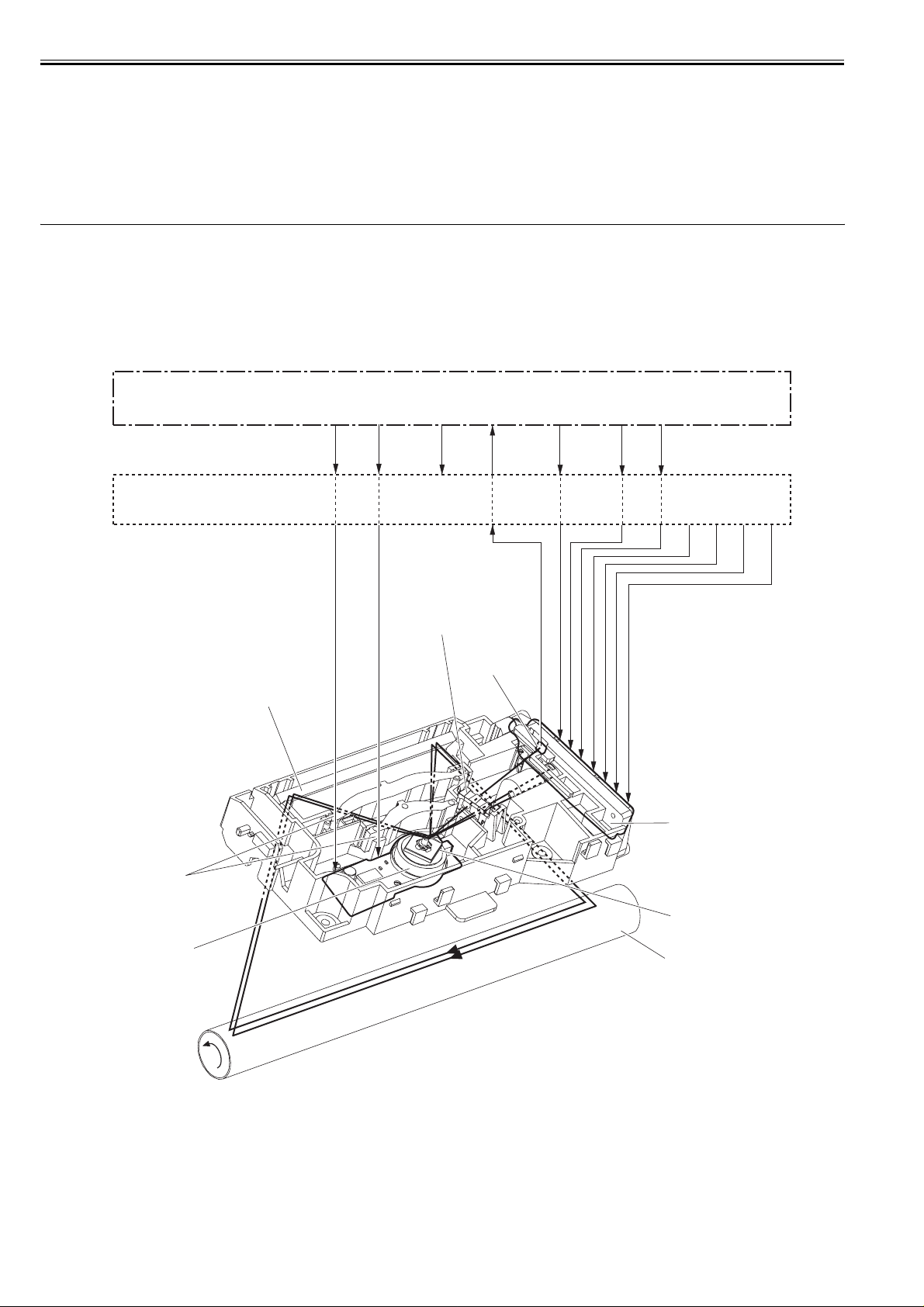
Chapter 2
5) Main motor initial drive
6) Fixing heater initial drive
Drive the fixing heater to reach the targeted temperature of 100 deg C
7) Scanner motor initial drive
8) High-voltage control
Detect the presence of cartridge and clean the transfer charging roller after the primary charging AC bias is turned ON
9) Failure/Abnormality check
Detect the scanner failure, the fixing unit failure, and the door open during this period
10) Memory tag communication
2.3 LASER EXPOSURE SYSTEM
2.3.1 Overview/Configuration
2.3.1.1 Outline
LBP3370 / LBP3310
The laser/scanner system consists of the laser driver and the scanner motor etc. It is controlled by the signals sent from the engine controller and the video controller.
The laser driver allows the laser diode to emit light according to the LASER CONTROL signals (CNT0, CNT1, CNT2) from the engine controller or the VIDEO
signals (/VDO1, /VDO2, VDO1, VDO2) from the video controller.
0018-3093
Engine controller PCB
/ACC /DEC
Video controller PCB
/BDO /BDI CNT0 CNT1
CNT2
VDO1
/VDO1
VDO2
/VDO2
Cylindrical lens
BD sensor
Mirror
Laser driver PCB
Focusing lens
Four-sided mirror
Scanner motor
Photsensitive drum
F-2-2
The laser/scanner unit of this printer utilizes a "twin beam method" (see Note). It scans two lines simultaneously with 2 laser diodes in order to realize a high-speed
laser scanning.
The operational sequence of the laser/scanner unit is described below.
1) When the video controller sends a print command, the engine controller rotates the scanner motor in order to rotate the four-sided mirror.
2) When the scanner motor starts to rotate, the engine controller forces the laser to emit light with the LASER CONTROL signal and then it starts to c ontrol the
scanner motor rotation.
3) The engine controller controls the scanner motor to rotate at a constant speed with the SCANNER MOTOR SPEED CONTROL signal.
4) The video controller sends the VIDEO signals to the laser driver PCB after the scanner motor rotation reaches its targeted speed.
5) The laser driver allows two laser diodes to emit light according to these signals.
2-2
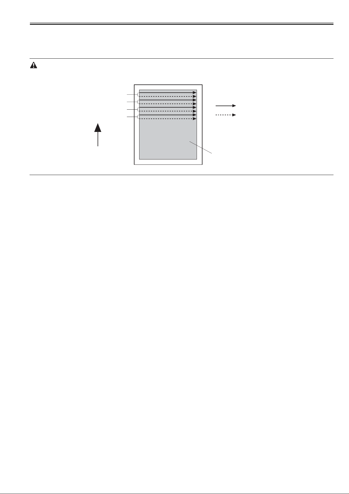
Chapter 2
6) The two laser beams pass through the collimator lens and the cylindrical lens to strike the four-sided mirror, which is rotating at a constant speed.
7) The laser beam reflected by the four-sided mirror focuses on the photosensitive drum passing through the focus lens and the reflective mirror at the front of the
four-sided mirror.
8) When the four-sided mirror starts to rotate at prescribed speed, the laser beam on the photosensitive drum starts to scan the surface of the drum at its prescribed
speed.
9) When the photosensitive drum rotates and the laser beam scans on the drum at each prescribed speed, the latent image is formed on the photosensitive drum.
Twin beam method
The laser unit unifies with two laser diodes (LD1, LD2). In one scanning operation, the two diodes (LD1, LD2) emit light to write two lines simultaneously.
This enables a twofold printing with same printing speed.
1st scanning line
2nd scanning line
3rd scanning line
4th scanning line
LD1 scanning line
LD2 scanning line
Feed direction
Image area
F-2-3
2.3.1.2 Laser Control Circuit
LBP3370 / LBP3310
The laser control controls the laser driver to turn the two laser diodes (LD1, LD2) ON/OFF according to the LASER CONTROL signals sent from the engine con-
troller.
The circuit diagram of the laser control is illustrated below.
0018-3094
2-3
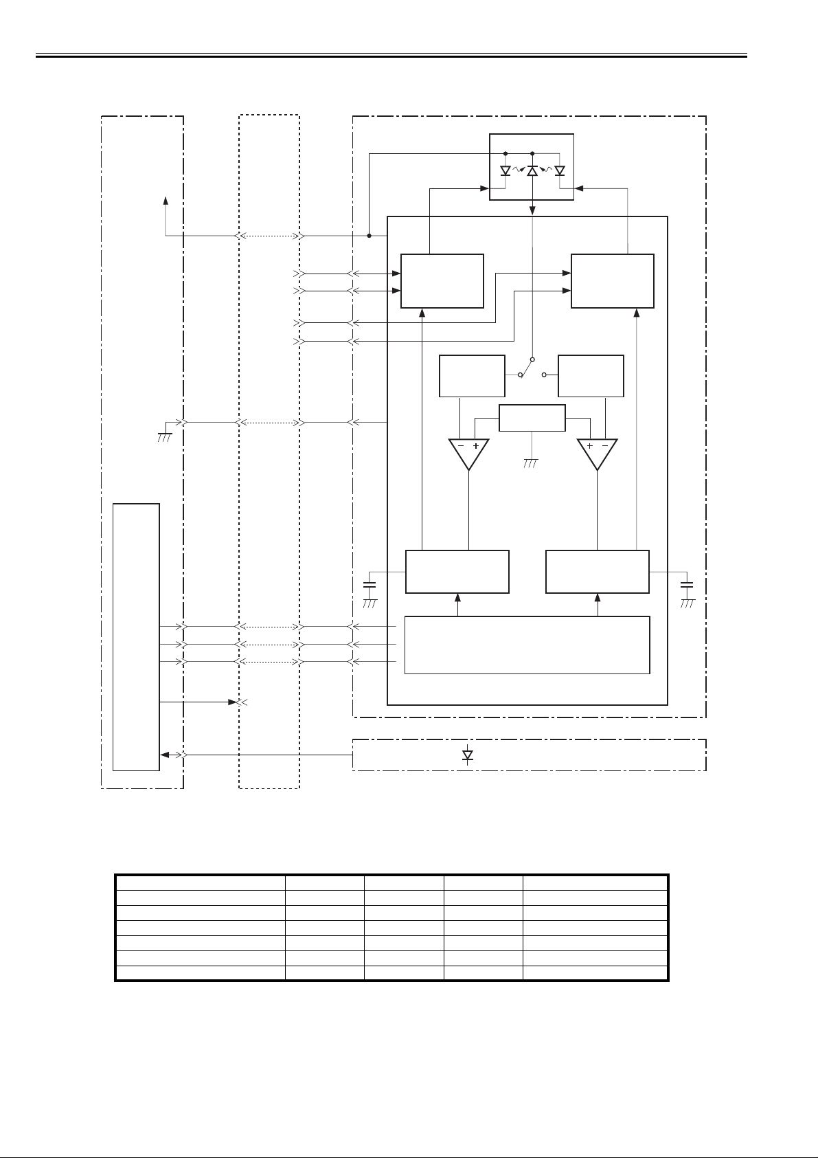
Chapter 2
Engine
controller PCB
+5V
Video
controller PCB
J201
-12
J801
-14
VDO1
/VDO1
VDO2
/VDO2
-16 -7
Laser driver PCB
PD
LD1
LD2
VCC
-6
-5
LD1
switching
circuit
LD2
switching
circuit
-8
-9
GND
Comparator
Reference
voltage
Comparator
IC201
Sample
CPU
/CNT0
/CNT1
/CNT2
/BDO
/BDI
The DC controller sends the VIDEO signals (VDO1, /VDO1, VDO2, /VDO2) and the LASER CONTROL signals (CNT0, CNT1, CNT2) to the logic circuit in the
laser driver IC. The VIDEO signals are for image formation and the LASER CONTROL signals are for switching the operational modes of the laser. The laser
driver IC controls the laser according to the combination of the CNT0, CNT1, and CNT2.
The table below indicates combinations of the LASER CONTROL signals (CNT0, CNT1, CNT2).
Discharge mode L L L C802, C803 discharge
Data output mode H H H Used during normal printing
LD1 APC mode L H L Used during LD1 APC mode
LD2 APC mode L L H Used during LD2 APC mode
Force LD1, LD2 ON H L L Used during test printing
Force LD1, LD2 OFF L H H Used during image masking period
-20
-19
-18
-14
-17
Operation mode CNT2 CNT1 CNT0 Remarks
CNT0
CNT1
CNT2
-1
-2
-3
-13
F-2-4
T-2-2
hold circuit
Logic circuit
Laser driver IC
BD PCB
Sample
hold circuit
C803C802
This control incorporates the LASER CONTROL signals for the following 4 controls:
1) Laser emission control
2) Automatic power control (APC)
3) Horizontal synchronization control
4) Image masking control
2-4

2.3.2 Controlling the Laser Activation Timing
Chapter 2
2.3.2.1 Laser emission control
LBP3370 / LBP3310
The laser emission control controls the laser diodes (LD1, LD2) to turn ON/OFF at constant light intensity according to the VIDEO signals (VDO1, /VDO1, VDO2,
/VDO2) from the video controller.
When the LASER CONTROL signals (CNT0, CNT1, CNT2) are put into print mode, the laser driver turns the laser diodes ON/OFF according to the VIDEO sig-
0018-3095
nals.
2.3.2.2 Horizontal synchronous control
LBP3370 / LBP3310
The horizontal synchronous control is to horizontally align the starting position of writing the image.
The following is the sequence of this control.
1) The DC controller puts the LASER CONTROL signal into LD1APCON mode or LD2APCON mode during the unblanking interval (see Note). Accordingly,
the laser driver allows the laser diode (LD1, LD2) to emit light with APC.
2) Each laser beam is sent to the BD PCB in the scanning optical path of the laser beam.
3) The BD PCB detects these laser beams, generates BD INPUT signal (/BDI), and sends it to the DC controller.
4) The DC controller generates the HORIZONTAL SYNCHRONOUS signal (/BDO) based on the /BDI signal and sends the /BPO signal to the video controller.
5) The video controller outputs the VIDEO signals (VDO1, /VDO1, VDO2, /VDO2) to the DC controller to horizontally align the starting position of writing the
image, when it inputs the /BDO signal
Unblanking interval
The interval when a laser diode emits light in the non-image area.
0018-3096
2.3.3 Laser Control
2.3.3.1 Automatic power control (APC)
LBP3370 / LBP3310
The automatic power control is to maintain the light intensity emitted from the laser diode to be constant.
There are two APCs, one is the initial APC (Note 1) and the other is the between-lines APC (Note 2). Both are controlled by the laser driver in the same way. The
following is the sequence of this control.
1) When the LASER CONTROL signals (CNT0, CNT1, CNT2) put into the LD1APC mode, the laser driver allows the LD1 to emit light.
2) The light intensity of the LD1 is detected by the photo diode (PD) and it is converted from current to voltage. Then it is compared with the reference voltage
(voltage equivalent to the target laser light intensity).
3) The laser driver controls the laser current until it reaches the voltage level of the LD1's targeted light intensity.
4) The LD1 is turned OFF forcefully when the LASER CONTROL signal puts into the force LD OFF mode. The laser driver stores the adjusted light intensity in
C802.
5) After the light intensity adjustment of LD1 is completed, the LASER CONTROL signal puts into the LD2APCON mode and the laser driver allows the LD2 to
emit light with APC. The laser light intensity of LD2 is adjusted and stored in C803 as same as LD1.
0018-3097
1) Initial APC
Performed during the INTER period. It adjusts the laser light intensity by APC.
2) Between-lines APC
Performed during the printing period. It adjusts the laser light intensity for one line before the line starts to be written.
2.3.3.2 Image masking control
LBP3370 / LBP3310
0018-3098
The image masking control is to prevent a laser beam emission in the non-image area except during the unblanking interval.
The engine controller puts the LASER CONTROL signal into the Force LD OFF mode and turns the laser diodes (LD1, LD2) OFF forcefully, while the laser scans
a non-image area except during the unblanking interval. This is called the image-masked status, and the laser diodes (LD1, LD2) do not emit light during this period
even if the VIDEO signals (VDO1, /VDO1, VDO2, /VDO2) are sent. The timing to start the image masking control depends on the paper size information sent
from the video controller.
If the paper size measured by the top of pag e sensor (PS912) is smaller than the paper size information, the engine controller masks the image forcefully to prevent
the transfer charging roller to be soiled.
2-5
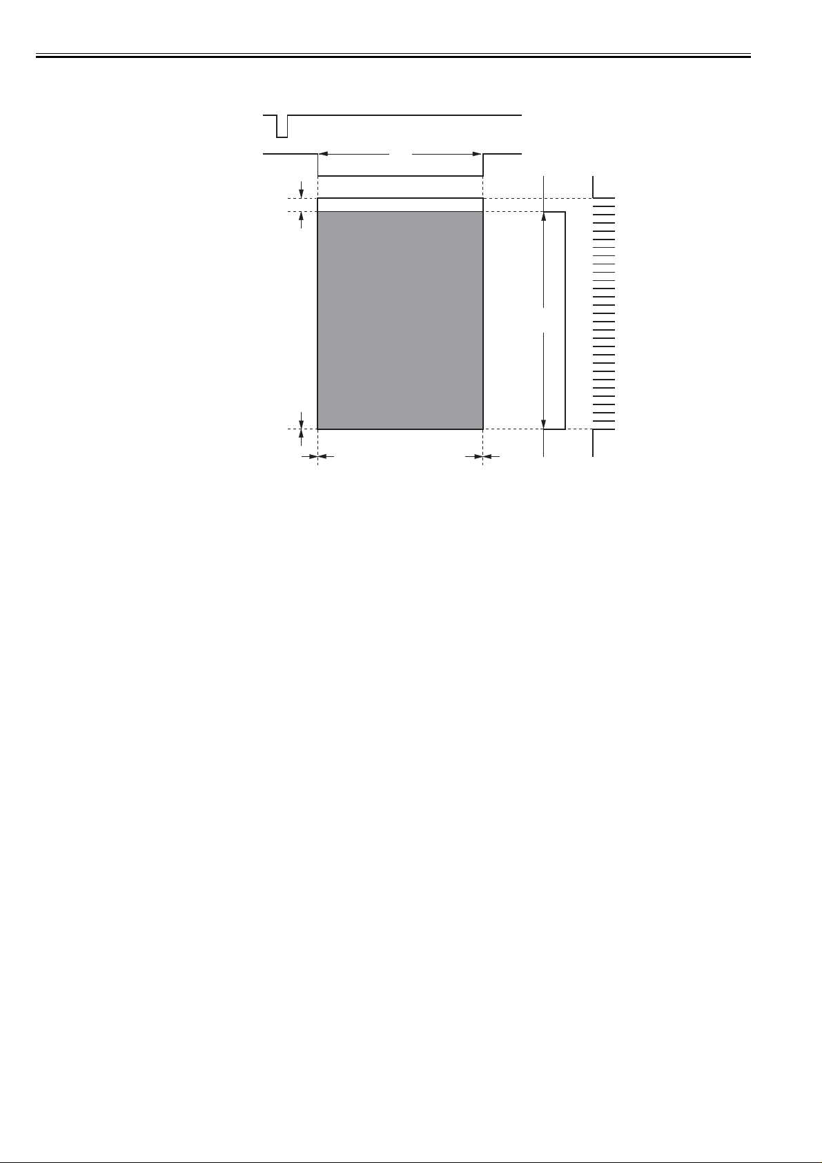
Chapter 2
/BDO
Unmasking area
T1
Unmasking area
2 mm
T2
0 mm
0 mm 0 mm
F-2-5
1) The shaded area indicates the area an image can be written by the laser beam.
2) T1 indicates the area of left /right outsides 0 mm of letter sized paper despite a paper size is specified or not.
3) T2 indicates the area of 2 mm behind the leading edge of the paper (where the /BDO signal starts to output) to the trailing edge.
/BDO
2.3.4 Laser Scanner Motor Control
2.3.4.1 Outline
LBP3370 / LBP3310
The scanner motor control is to rotate the scanner motor in order to strike the laser beam at the correct position on the photosensitive drum.
The circuit diagram of the scanner motor control is illustrated below.
0018-3102
2-6
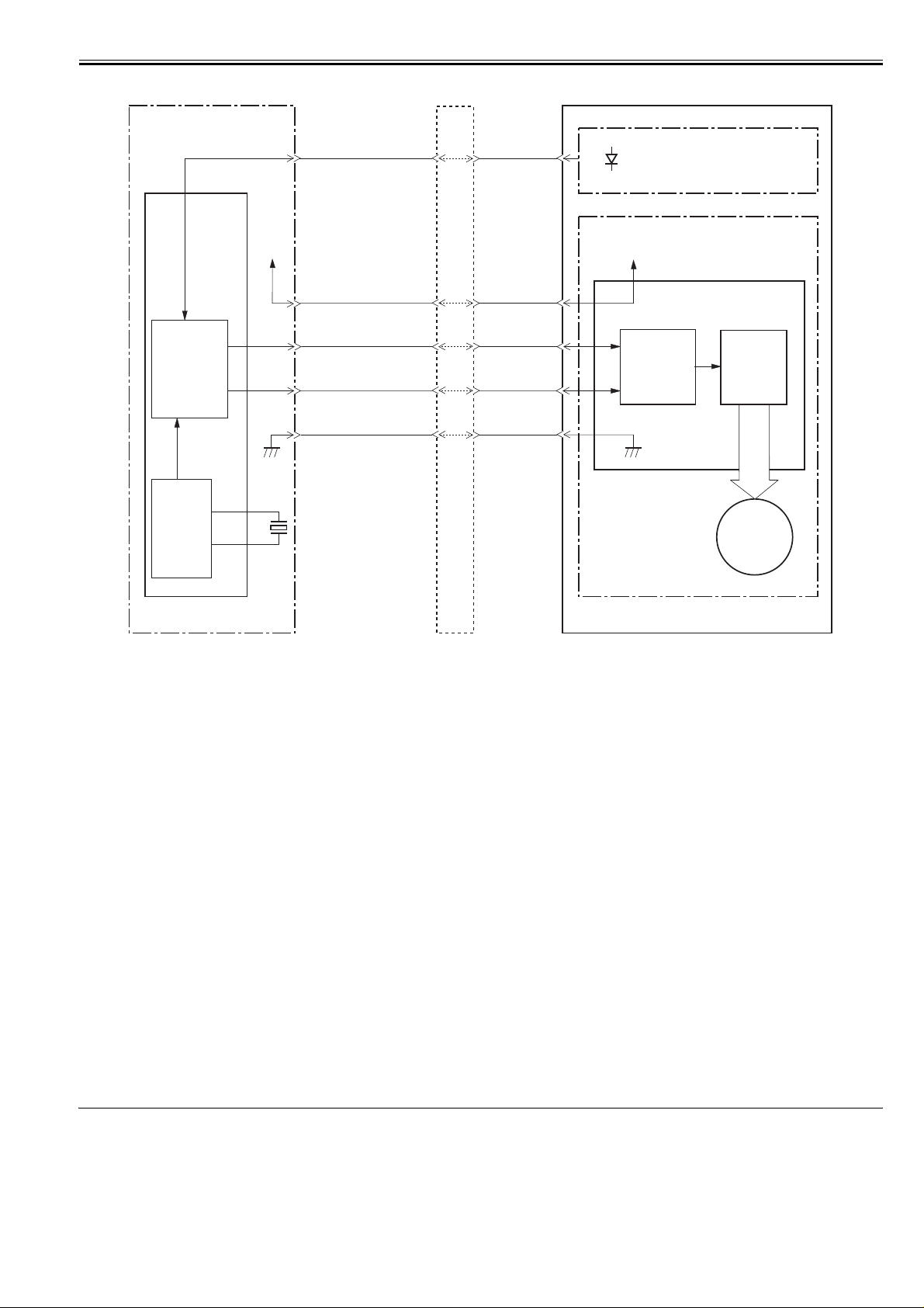
Chapter 2
IC201
CPU
Frequency
comparator
Reference
clock
Divider
+24VA
X201
J201
-17
-27
-21
-22
-16
/BDI
/ACC
/DEC
Video controller PCBEngine controller PCB
J801
J7
-12
J3
-13
-13
Laser/scanner unit
BD sensor
+24VA
J2
-2
-8
-7
-13
J812
-1
-2
-3
-4
-1
-2
-3
-4
Scanner driver IC
Integrated
circuit
Drive
circuit
M
Scanner motor
F-2-6
2.3.4.2 Scanner motor speed control
LBP3370 / LBP3310
The scanner motor is 3-phase DC brushless motor unified with the hole effect device and it is unified with the drive circuit.
When the printer is turned ON, the CPU (IC201) divides the oscillated frequency of the crystal oscillator (X201) and generates the reference clock.
The CPU puts the SCANNER MOTOR ACCELERATION signal (/ACC) into "L" and the DECELERATION signal (/DEC) into "H", when the print command is
sent from the video controller.
Then the scanner driver IC rotates the scanner motor when the /ACC signal puts into "L". The scanner motor increases the rotational count only during the /ACC
signal is "L".
The CPU allows the laser to emit light with APC during the scanner motor is rotating. Accordingly, the BD INPUT signal (/BDI) is sent to the CPU from the BD
sensor via the video controller. The CPU compares the intervals between the /BDI signal and the reference clock with the frequency comparator in the CPU, and
controls the rotational count of the scanner motor by controlling the /ACC signal until the rotational count reaches its prescribed count.
The CPU decreases the rotational count of the scanner motor by putting the SCANNER MOTOR DECRELATION signal (/DEC) into "L" and the ACCELERATION signal (/ACC) into "H" to stop the scanner motor.
2.3.4.3 Scanner motor failure detection
LBP3370 / LBP3310
The CPU monitors the /BDI signal from the BD sensor via the video controller, and determines if the scanner motor rotates at its prescribed rotational count or not.
The CPU determines the failure or the error and notifies it to the video controller under the following conditions.
1) Scanner failure
When the /BDI signal is not detected within 0.9 sec. after the forced acceleration of the scanner motor is completed, it is detected for another 60 sec, and if the
interval of the /BDI signal cannot be detected at specified amount during this period.
2) BD failure
If the /BDI signal is not detected within 100msec. after the forced acceleration of the scanner motor. Or if the interval of the /BDI signal is not detected at a
specified value for longer than 2 sec. continuously, after the scanner motor reaches its prescribed rotational count.
3) BD error
If the /BDI signal is not detected in the prescribed interval during the CPU is outputting the /BD signal to the video controller.
Exceptional cases:
If the door open is detected within 200 msec. after the BD error is detected, the CPU does not notify the BD error to the video controller.
Also if the scanner failure or the BD failure is detected after the BD error is detected, the CPU releases the BD error.
0018-3101
0018-3103
2.4 IMAGE FORMATION SYSTEM
2.4.1 Overview/Configuration
2.4.1.1 Outline
LBP3370 / LBP3310
The image formation system serves as the nerve center of the printer. It consists of the cartridge, the transfer charging roller, and the fixing unit etc.
0018-3104
2-7
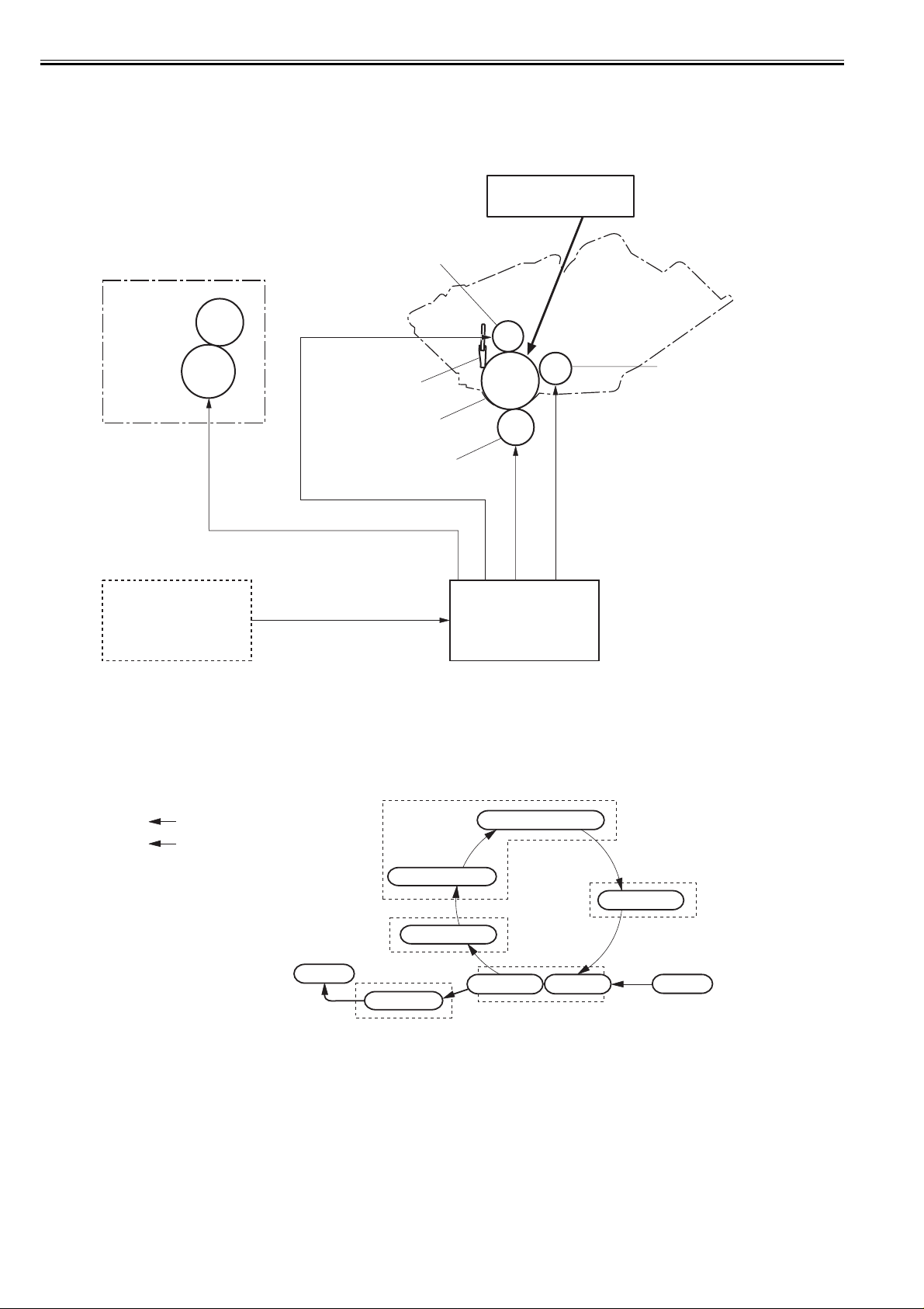
Chapter 2
When the engine controller receives print command from the video controller, it drives the main motor in order to rotate the followings: photosensitive drum, developing cylinder, primary charging roller, transfer charging roller and pressure roller.
The primary charging roller allows the surface of the photosensitive drum to charge evenness negative. At the same time, the laser beam, modulated by the VIDEO
signals (VDO1, VDO2, /VDO1, /VDO2), is emitted onto the surface of photosensitive drum in order to format the latent image on the drum by the laser diode.
The latent image formed on the photosensitive drum is transferred into a visible image by the toner on the developing cylinder and the transfer charging roller transfers it onto a print paper. Then the transferred toner onto a paper becomes a permanent image by heat and pressure in the fixing unit. After the surface of the photosensitive drum is cleaned by the cleaning blade, the drum potential is uniformed by the primary charging roller to get ready for the next print.
Laser/Scanner unit
Laser beam
Primary charging roller
Fixing unit
Fixing film unit
Cartridge
Developing cylinder
Cleaning blade
Pressure roller
Photosensitive drum
Transfer charging roller
VIDEO signals (VDO, /VDO)
Video controller PCB
Engine controller PCB
Print command
F-2-7
2.4.1.2 Print Process
LBP3370 / LBP3310
The principal process of the image formation is described in this paragraph.
The process can be broadly divided into 5 blocks with 7 steps. A toner image is formed on a print paper as it goes step by step in each block.
Electrostatic latent image formation block
Paper path
2. Laser beam exposure
Rotational direction of the drum
1. Primary charging
Photosensitive drum cleaning block
Delivery
1. Electrostatic latent image formation block
Form an electrostatic latent image on the photosensitive drum.
Step 1: Primary charging (Charge the surface of the photosensitive drum uniformed negative potential)
Step 2: Laser beam exposure (Form an electrostatic latent image on the photosensitive drum)
2. Developing block
Make an electrostatic latent image on the photosensitive drum visible by applying the toner on.
Step 3: Development
3. Transfer block
Transfer a toner image on the photosensitive drum surface onto a print paper.
Step 4: Transfer (Transfer a toner on the photosensitive drum onto a print paper)
Step 5: Separation (Remove a paper from the photosensitive drum)
4. Fixing block
Fix a toner image on a print paper.
Step 6: Fixing
7. Drum cleaning
Fixing block
6. Fixing
F-2-8
5. Separation 4. Transfer
Transfer block
Developing block
3. Developing
Pick-up
0018-3105
2-8
 Loading...