


Mar 31 2006
Service Manual
MF3220 Series
LaserBase MF3220


Application
This manual has been issued by Canon Inc. for qualified persons to learn technical theory, installation, maintenance, and repair
of products. This manual covers all localities where the products are sold. For this reason, there may be information in this
manual that does not apply to your locality.
Corrections
This manual may contain technical inaccuracies or typographical errors due to improvements or changes in products. When
changes occur in applicable products or in the contents of this manual, Canon will release technical information as the need
arises. In the event of major changes in the contents of this manual over a long or short period, Canon will issue a new edition
of this manual.
The following paragraph does not apply to any countries where such provisions are inconsistent with local law.
Trademarks
The product names and company names used in this manual are the registered trademarks of the individual companies.
Copyright
This manual is copyrighted with all rights reserved. Under the copyright laws, this manual may not be copied, reproduced or
translated into another language, in whole or in part, without the written consent of Canon Inc.
COPYRIGHT © 2001 CANON INC.
Printed in Japan
Caution
Use of this manual should be strictly supervised to avoid disclosure of confidential information.
Introduction
Symbols Used
This documentation uses the following symbols to indicate special information:
Symbol Description
Indicates an item of a non-specific nature, possibly classified as Note, Caution, or Warning.
Indicates an item requiring care to avoid electric shocks.
Indicates an item requiring care to avoid combustion (fire).
Indicates an item prohibiting disassembly to avoid electric shocks or problems.
Indicates an item requiring disconnection of the power plug from the electric outlet.
Indicates an item intended to provide notes assisting the understanding of the topic in question.
Indicates an item of reference assisting the understanding of the topic in question.
Provides a description of a service mode.
Provides a description of the nature of an error indication.
Memo
REF.

Introduction
The following rules apply throughout this Service Manual:
1. Each chapter contains sections explaining the purpose of specific functions and the relationship between electrical and mechanical systems with reference to the timing of operation.
In the diagrams, represents the path of mechanical drive; where a signal name accompanies the symbol , the arrow indicates the
direction of the electric signal.
The expression "turn on the power" means flipping on the power switch, closing the front door, and closing the delivery unit door, which results in
supplying the machine with power.
2. In the digital circuits, '1'is used to indicate that the voltage level of a given signal is "High", while '0' is used to indicate "Low".(The voltage value, however, differs from circuit to circuit.) In addition, the asterisk (*) as in "DRMD*" indicates that the DRMD signal goes on when '0'.
In practically all cases, the internal mechanisms of a microprocessor cannot be checked in the field. Therefore, the operations of the microprocessors
used in the machines are not discussed: they are explained in terms of from sensors to the input of the DC controller PCB and from the output of the
DC controller PCB to the loads.
The descriptions in this Service Manual are subject to change without notice for product improvement or other purposes, and major changes will be communicated in the form of Service Information bulletins.
All service persons are expected to have a good understanding of the contents of this Service Manual and all relevant Service Information bulletins and be
able to identify and isolate faults in the machine."


Contents
Contents
Chapter 1 PRODUCT DESCRIPTION
1.1 Product Specifications ................................................................................................................................1- 1
1.1.1 Product Specifications(EU/AE/CN/KOR).................................................................................................................1- 1
1.2 Detailed Specifications ...............................................................................................................................1- 1
1.2.1 Printing Speed ........................................................................................................................................................ 1- 1
1.2.2 Stack Upon Delivery ................................................................................................................................................1- 2
1.2.3 System Requirements for Printer Driver ..................................................................................................................1- 2
1.3 Names of Parts ........................................................................................................................................... 1- 2
1.3.1 External View...........................................................................................................................................................1- 2
1.3.2 Operation panel ....................................................................................................................................................... 1- 3
1.4 Safety ......................................................................................................................................................... 1- 4
1.4.1 Safety of Laser Light................................................................................................................................................1- 4
1.4.2 Regulations Under the Center for Devices and Radiological Health (CDRH) .........................................................1- 4
1.4.3 Handling the Laser Unit ...........................................................................................................................................1- 4
1.4.4 Safety of Toner........................................................................................................................................................1- 4
1.4.5 Backup Battery .......................................................................................................................................................1- 5
Chapter 2 TECHNICAL REFERENCE
2.1 Document Feed and Exposure System ......................................................................................................2- 1
2.1.1 Overview/Configuration ...........................................................................................................................................2- 1
2.1.1.1 Overview .................................................................................................................................................................................. 2- 1
2.2 Laser Exposure ..........................................................................................................................................2- 2
2.2.1 Overview/Configuration ...........................................................................................................................................2- 2
2.2.1.1 Overview .................................................................................................................................................................................. 2- 2
2.3 Image Formation ........................................................................................................................................2- 3
2.3.1 Overview/Configuration ...........................................................................................................................................2- 3
2.3.1.1 Overview .................................................................................................................................................................................. 2- 3
2.4 Pickup and Feed System............................................................................................................................ 2- 4
2.4.1 Overview/Configuration ...........................................................................................................................................2- 4
2.4.1.1 Overview .................................................................................................................................................................................. 2- 4
2.4.2 Other Control ........................................................................................................................................................... 2- 4
2.4.2.1 Manual Pickup Control ............................................................................................................................................................. 2- 4
2.4.2.2 Cassette Pickup Control .......................................................................................................................................................... 2- 4
2.4.3 Detection Jams........................................................................................................................................................2- 5
2.4.3.1 Jam Detection Outline.............................................................................................................................................................. 2- 5
2.4.3.2 Delay Jams .............................................................................................................................................................................. 2- 5
2.4.3.3 Stationary Jams ....................................................................................................................................................................... 2- 5
2.4.3.4 Other Jams .............................................................................................................................................................................. 2- 5
2.5 Fixing Unit...................................................................................................................................................2- 6
2.5.1 Overview/Configuration ...........................................................................................................................................2- 6
2.5.1.1 Overview .................................................................................................................................................................................. 2- 6
2.5.2 Protection Function..................................................................................................................................................2- 6
2.5.2.1 Protective Mechanisms ............................................................................................................................................................ 2- 6
2.5.2.2 Detecting a Fault in the Fixing Assembly ................................................................................................................................. 2- 6
2.6 External and Controls ................................................................................................................................. 2- 7
2.6.1 Power Supply ..........................................................................................................................................................2- 7
2.6.1.1 Backup Battery......................................................................................................................................................................... 2- 7
Chapter 3 DISASSEMBLY AND ASSEMBLY

Contents
3.1 EXTERNAL AND CONTROLS SYSTEM ................................................................................................... 3- 1
3.1.1 Front Cover..............................................................................................................................................................3- 1
3.1.1.1 Removing the Cassette............................................................................................................................................................ 3- 1
3.1.1.2 Removing the front cover ......................................................................................................................................................... 3- 1
3.1.2 Rear Cover...............................................................................................................................................................3- 1
3.1.2.1 Removing the Cassette............................................................................................................................................................ 3- 1
3.1.2.2 Removing the front cover ......................................................................................................................................................... 3- 1
3.1.2.3 Removing the right cover ......................................................................................................................................................... 3- 1
3.1.2.4 Removing the left cover ........................................................................................................................................................... 3- 1
3.1.2.5 Removing the rear cover.......................................................................................................................................................... 3- 1
3.1.3 Top Cover ................................................................................................................................................................3- 2
3.1.3.1 Removing the Cassette............................................................................................................................................................ 3- 2
3.1.3.2 Removing the front cover ......................................................................................................................................................... 3- 2
3.1.3.3 Removing the right cover ......................................................................................................................................................... 3- 2
3.1.3.4 Removing the left cover ........................................................................................................................................................... 3- 2
3.1.3.5 Removing the rear cover.......................................................................................................................................................... 3- 2
3.1.3.6 Removing the Scanner Unit ..................................................................................................................................................... 3- 2
3.1.3.7 Removing the top cover ........................................................................................................................................................... 3- 3
3.1.4 Right Cover..............................................................................................................................................................3- 3
3.1.4.1 Removing the Cassette............................................................................................................................................................ 3- 3
3.1.4.2 Removing the front cover ......................................................................................................................................................... 3- 3
3.1.4.3 Removing the right cover ......................................................................................................................................................... 3- 3
3.1.5 Left Cover ................................................................................................................................................................3- 3
3.1.5.1 Removing the Cassette............................................................................................................................................................ 3- 3
3.1.5.2 Removing the left cover ........................................................................................................................................................... 3- 3
3.1.6 Operation Panel Unit................................................................................................................................................3- 4
3.1.6.1 Removung the Cassette .......................................................................................................................................................... 3- 4
3.1.6.2 Removing the front cover ......................................................................................................................................................... 3- 4
3.1.6.3 Removing the right cover ......................................................................................................................................................... 3- 4
3.1.6.4 Removing the left cover ........................................................................................................................................................... 3- 4
3.1.6.5 Removing the rear cover.......................................................................................................................................................... 3- 4
3.1.6.6 Removing the Scanner Unit ..................................................................................................................................................... 3- 5
3.1.6.7 Removing the Board Unit ......................................................................................................................................................... 3- 5
3.1.6.8 Removing the Operation Panel Unit ........................................................................................................................................ 3- 5
3.1.7 SCNT Board.............................................................................................................................................................3- 6
3.1.7.1 Removing the Cassette............................................................................................................................................................ 3- 6
3.1.7.2 Removing the front cover ......................................................................................................................................................... 3- 6
3.1.7.3 Removing the right cover ......................................................................................................................................................... 3- 6
3.1.7.4 Removing the left cover ........................................................................................................................................................... 3- 6
3.1.7.5 Removing the rear cover.......................................................................................................................................................... 3- 6
3.1.7.6 Removing the Scanner Unit ..................................................................................................................................................... 3- 6
3.1.7.7 Removing the SCNT Board ..................................................................................................................................................... 3- 7
3.1.8 ECNT Board.............................................................................................................................................................3- 7
3.1.8.1 Removing the Cassette............................................................................................................................................................ 3- 7
3.1.8.2 Removing the front cover ......................................................................................................................................................... 3- 7
3.1.8.3 Removing the left cover ........................................................................................................................................................... 3- 7
3.1.8.4 Removing the ECNT Board ..................................................................................................................................................... 3- 7
3.1.9 Power Supply PCB ..................................................................................................................................................3- 8
3.1.9.1 Removing the Cassette............................................................................................................................................................ 3- 8
3.1.9.2 Removing the front cover ......................................................................................................................................................... 3- 8
3.1.9.3 Removing the right cover ......................................................................................................................................................... 3- 8
3.1.9.4 Removing the left cover ........................................................................................................................................................... 3- 8
3.1.9.5 Removing the rear cover.......................................................................................................................................................... 3- 8
3.1.9.6 Removing the Power Supply Shield Plate ............................................................................................................................... 3- 8
3.1.9.7 Removing the Power Supply Assembly ................................................................................................................................... 3- 9
3.1.9.8 Removing the Power Supply Board ......................................................................................................................................... 3- 9
3.1.10 High-voitage Power Supply PCB ...........................................................................................................................3- 9
3.1.10.1 Removing the Cassette.......................................................................................................................................................... 3- 9
3.1.10.2 Removing the front cover ....................................................................................................................................................... 3- 9
3.1.10.3 Removing the right cover ....................................................................................................................................................... 3- 9

Contents
3.1.10.4 Removing the left cover ....................................................................................................................................................... 3- 10
3.1.10.5 Removing the rear cover ...................................................................................................................................................... 3- 10
3.1.10.6 Removing the Power Supply Shield Plate............................................................................................................................ 3- 10
3.1.10.7 Removing the Power Supply Board ..................................................................................................................................... 3- 10
3.1.10.8 Removing the High-Voltage Power Supply Board ............................................................................................................... 3- 11
3.1.11 Top Sensor ..........................................................................................................................................................3- 11
3.1.11.1 Removing the Cassette ........................................................................................................................................................ 3- 11
3.1.11.2 Removing the front cover ..................................................................................................................................................... 3- 11
3.1.11.3 Removing the right cover ..................................................................................................................................................... 3- 11
3.1.11.4 Removing the left cover ....................................................................................................................................................... 3- 11
3.1.11.5 Removing the rear cover ...................................................................................................................................................... 3- 12
3.1.11.6 Removing the Scanner Unit ................................................................................................................................................. 3- 12
3.1.11.7 Removing the top cover ....................................................................................................................................................... 3- 12
3.1.11.8 Removing the Right Frame .................................................................................................................................................. 3- 12
3.1.11.9 Removing the Plate.............................................................................................................................................................. 3- 12
3.1.11.10 Removing the Left Frame ................................................................................................................................................... 3- 13
3.1.11.11 Removing the Power Supply Shield Plate .......................................................................................................................... 3- 13
3.1.11.12 Removing the Power Supply Assembly ............................................................................................................................. 3- 13
3.1.11.13 Removing the top sensor ................................................................................................................................................... 3- 13
3.1.12 Paper Delivery Sensor.........................................................................................................................................3- 14
3.1.12.1 Removing the Cassette ........................................................................................................................................................ 3- 14
3.1.12.2 Removing the front cover ..................................................................................................................................................... 3- 14
3.1.12.3 Removing the right cover ..................................................................................................................................................... 3- 14
3.1.12.4 Removing the left cover ....................................................................................................................................................... 3- 14
3.1.12.5 Removing the rear cover ...................................................................................................................................................... 3- 14
3.1.12.6 Removing the Power Supply Shield Plate............................................................................................................................ 3- 14
3.1.12.7 Removing the Scanner Unit ................................................................................................................................................. 3- 15
3.1.12.8 Removing the Plate.............................................................................................................................................................. 3- 15
3.1.12.9 Removing the Paper Delivery Sensor .................................................................................................................................. 3- 15
3.2 Document Feed/Exposure System ...........................................................................................................3- 15
3.2.1 Scanner Unit..........................................................................................................................................................3- 15
3.2.1.1 Removing the Cassette.......................................................................................................................................................... 3- 15
3.2.1.2 Removing the front cover ....................................................................................................................................................... 3- 15
3.2.1.3 Removing the right cover ....................................................................................................................................................... 3- 16
3.2.1.4 Removong the left cover ........................................................................................................................................................ 3- 16
3.2.1.5 Removing the rear cover........................................................................................................................................................ 3- 16
3.2.1.6 Removing the Scanner Unit ................................................................................................................................................... 3- 16
3.2.2 Scanner Cover Unit ...............................................................................................................................................3- 17
3.2.2.1 Removing the Cassette.......................................................................................................................................................... 3- 17
3.2.2.2 Removing the front cover ....................................................................................................................................................... 3- 17
3.2.2.3 Removing the right cover ....................................................................................................................................................... 3- 17
3.2.2.4 Removing the left cover ......................................................................................................................................................... 3- 17
3.2.2.5 Removing the rear cover........................................................................................................................................................ 3- 17
3.2.2.6 Removing the Scanner Unit ................................................................................................................................................... 3- 17
3.2.2.7 Removing the Operation Panel Unit ...................................................................................................................................... 3- 18
3.2.2.8 Scanner cover unit ................................................................................................................................................................. 3- 18
3.2.3 Contact Sensor......................................................................................................................................................3- 18
3.2.3.1 Removing the Cassette.......................................................................................................................................................... 3- 18
3.2.3.2 Removing the front cover ....................................................................................................................................................... 3- 18
3.2.3.3 Removing the right cover ....................................................................................................................................................... 3- 18
3.2.3.4 Removing the left cover ......................................................................................................................................................... 3- 19
3.2.3.5 Removing the rear cover........................................................................................................................................................ 3- 19
3.2.3.6 Removing the Scanner Unit ................................................................................................................................................... 3- 19
3.2.3.7 Removing the Operation Panel Unit ...................................................................................................................................... 3- 19
3.2.3.8 Removing the Scanner Cover Unit ........................................................................................................................................ 3- 20
3.2.3.9 Removing the Flatbed Motor Unit .......................................................................................................................................... 3- 20
3.2.3.10 Removing the Contact Sensor ............................................................................................................................................. 3- 20
3.2.4 Flatbed Motor Unit ................................................................................................................................................. 3- 20
3.2.4.1 Removing the Cassette.......................................................................................................................................................... 3- 20
3.2.4.2 Removing the front cover ....................................................................................................................................................... 3- 20
3.2.4.3 Removing the right cover ....................................................................................................................................................... 3- 21

Contents
3.2.4.4 Removing the left cover ......................................................................................................................................................... 3- 21
3.2.4.5 Removing the rear cover........................................................................................................................................................ 3- 21
3.2.4.6 Removing the Scanner Unit ................................................................................................................................................... 3- 21
3.2.4.7 Removing the Operation Panel Unit ...................................................................................................................................... 3- 22
3.2.4.8 Removing the Scanner Cover Unit ........................................................................................................................................ 3- 22
3.2.4.9 Removing the Flatbed Motor Unit .......................................................................................................................................... 3- 22
3.3 LASER EXPOSURE SYSTEM ................................................................................................................. 3- 22
3.3.1 Laser/Scanner Unit ................................................................................................................................................3- 22
3.3.1.1 Removing the Cassette.......................................................................................................................................................... 3- 22
3.3.1.2 Removing the front cover ....................................................................................................................................................... 3- 22
3.3.1.3 Removing the right cover ....................................................................................................................................................... 3- 23
3.3.1.4 Removing the left cover ......................................................................................................................................................... 3- 23
3.3.1.5 Removing the rear cover........................................................................................................................................................ 3- 23
3.3.1.6 Removing the Scanner Unit ................................................................................................................................................... 3- 23
3.3.1.7 Removing the top cover ......................................................................................................................................................... 3- 24
3.3.1.8 Removing the Laser/Scanner Unit ......................................................................................................................................... 3- 24
3.4 IMAGE FORMATION SYSTEM................................................................................................................ 3- 24
3.4.1 Transfer Charging Roller........................................................................................................................................3- 24
3.4.1.1 Removing the Transfer Charging Roller ................................................................................................................................ 3- 24
3.5 PICKUP AND FEEDING SYSTEM........................................................................................................... 3- 24
3.5.1 Cassette Pickup Roller...........................................................................................................................................3- 24
3.5.1.1 Removing the Cassette.......................................................................................................................................................... 3- 24
3.5.1.2 Removing the front cover ....................................................................................................................................................... 3- 24
3.5.1.3 Removing the right cover ....................................................................................................................................................... 3- 25
3.5.1.4 Removing the left cover ......................................................................................................................................................... 3- 25
3.5.1.5 Removing the rear cover........................................................................................................................................................ 3- 25
3.5.1.6 Removing the Scanner Unit ................................................................................................................................................... 3- 25
3.5.1.7 Removing the top cover ......................................................................................................................................................... 3- 25
3.5.1.8 Removing the Right Frame .................................................................................................................................................... 3- 26
3.5.1.9 Removing the Plate................................................................................................................................................................ 3- 26
3.5.1.10 Removing the Left Frame..................................................................................................................................................... 3- 26
3.5.1.11 Removing the Power Supply Shield Plate............................................................................................................................ 3- 26
3.5.1.12 Removing the Power Supply Assembly ............................................................................................................................... 3- 26
3.5.1.13 Removing the Gear Unit....................................................................................................................................................... 3- 27
3.5.1.14 Removing the Tooth-Missing Gear ...................................................................................................................................... 3- 27
3.5.2 Cassette Pickup Solenoid......................................................................................................................................3- 27
3.5.2.1 Removing the Cassette.......................................................................................................................................................... 3- 27
3.5.2.2 Removing the front cover ....................................................................................................................................................... 3- 27
3.5.2.3 Removing the right cover ....................................................................................................................................................... 3- 27
3.5.2.4 Removing the left cover ......................................................................................................................................................... 3- 28
3.5.2.5 Removing the rear cover........................................................................................................................................................ 3- 28
3.5.2.6 Removing the Scanner Unit ................................................................................................................................................... 3- 28
3.5.2.7 Removing the top cover ......................................................................................................................................................... 3- 28
3.5.2.8 Removing the Right Frame .................................................................................................................................................... 3- 29
3.5.2.9 Removing the Plate................................................................................................................................................................ 3- 29
3.5.2.10 Removing the Left Frame..................................................................................................................................................... 3- 29
3.5.2.11 Removing the Power Supply Shield Plate............................................................................................................................ 3- 29
3.5.2.12 Removing the Power Supply Assembly ............................................................................................................................... 3- 29
3.5.2.13 Removing the Cassette Pickup Solenoid ............................................................................................................................. 3- 30
3.5.3 Cassette Separation Pad.......................................................................................................................................3- 30
3.5.3.1 Removing the Cassette.......................................................................................................................................................... 3- 30
3.5.3.2 Removing the Rear of the Cassette ....................................................................................................................................... 3- 30
3.5.3.3 Removing the Cassette Separation Pad ................................................................................................................................ 3- 30
3.5.4 Paper Feed Roller..................................................................................................................................................3- 30
3.5.4.1 Removing the Cassette.......................................................................................................................................................... 3- 30
3.5.4.2 Removing the front cover ....................................................................................................................................................... 3- 30
3.5.4.3 Removing the right cover ....................................................................................................................................................... 3- 30
3.5.4.4 Removing the left cover ......................................................................................................................................................... 3- 31
3.5.4.5 Removing the rear cover........................................................................................................................................................ 3- 31
3.5.4.6 Removing the Scanner Unit ................................................................................................................................................... 3- 31

Contents
3.5.4.7 Removing the top cover ......................................................................................................................................................... 3- 31
3.5.4.8 Removing the Right Frame .................................................................................................................................................... 3- 31
3.5.4.9 Removing the Plate................................................................................................................................................................ 3- 32
3.5.4.10 Removing the Left Frame..................................................................................................................................................... 3- 32
3.5.4.11 Removing the Power Supply Shield Plate............................................................................................................................ 3- 32
3.5.4.12 Removing the Power Supply Assembly ............................................................................................................................... 3- 32
3.5.4.13 Removing the Gear Unit....................................................................................................................................................... 3- 33
3.5.4.14 Removing the Tooth-Missing Gear ...................................................................................................................................... 3- 33
3.5.4.15 Removing the Manual Stay .................................................................................................................................................. 3- 33
3.5.4.16 Removing the Paper Feed Guide......................................................................................................................................... 3- 33
3.5.4.17 Removing the Paper Feed Roller ......................................................................................................................................... 3- 33
3.5.5 Manual Pickup Solenoid ........................................................................................................................................3- 34
3.5.5.1 Removing the Cassette.......................................................................................................................................................... 3- 34
3.5.5.2 Removing the front cover ....................................................................................................................................................... 3- 34
3.5.5.3 Removing the right cover ....................................................................................................................................................... 3- 34
3.5.5.4 Removing the left cover ......................................................................................................................................................... 3- 34
3.5.5.5 Removing the rear cover........................................................................................................................................................ 3- 34
3.5.5.6 Removing the Scanner Unit ................................................................................................................................................... 3- 34
3.5.5.7 Removing the top cover ......................................................................................................................................................... 3- 35
3.5.5.8 Removing the Right Frame .................................................................................................................................................... 3- 35
3.5.5.9 Removing the Plate................................................................................................................................................................ 3- 35
3.5.5.10 Removing the Left Frame..................................................................................................................................................... 3- 35
3.5.5.11 Removing the Power Supply Shield Plate............................................................................................................................ 3- 35
3.5.5.12 Removing the Power Supply Assembly ............................................................................................................................... 3- 36
3.5.5.13 Removing the Manual Pickup Solenoid ............................................................................................................................... 3- 36
3.5.6 Main Motor.............................................................................................................................................................3- 36
3.5.6.1 Removing the Cassette.......................................................................................................................................................... 3- 36
3.5.6.2 Removing the front cover ....................................................................................................................................................... 3- 36
3.5.6.3 Removing the right cover ....................................................................................................................................................... 3- 36
3.5.6.4 Removing the left cover ......................................................................................................................................................... 3- 37
3.5.6.5 Removing the rear cover........................................................................................................................................................ 3- 37
3.5.6.6 Removing the Scanner Unit ................................................................................................................................................... 3- 37
3.5.6.7 Removing the top cover ......................................................................................................................................................... 3- 37
3.5.6.8 Removing the Right Frame .................................................................................................................................................... 3- 38
3.5.6.9 Removing the Plate................................................................................................................................................................ 3- 38
3.5.6.10 Removing the Left Frame..................................................................................................................................................... 3- 38
3.5.6.11 Removing the Power Supply Shield Plate............................................................................................................................ 3- 38
3.5.6.12 Removing the Power Supply Assembly ............................................................................................................................... 3- 38
3.5.6.13 Removing the Main Motor .................................................................................................................................................... 3- 39
3.5.7 Gear Unit ...............................................................................................................................................................3- 39
3.5.7.1 Removing the Cassette.......................................................................................................................................................... 3- 39
3.5.7.2 Removing the front cover ....................................................................................................................................................... 3- 39
3.5.7.3 Removing the right cover ....................................................................................................................................................... 3- 39
3.5.7.4 Removing the Gear Unit ........................................................................................................................................................ 3- 39
3.6 FIXING SYSTEM ...................................................................................................................................... 3- 40
3.6.1 Fixing Film Unit......................................................................................................................................................3- 40
3.6.1.1 Removing the Cassette.......................................................................................................................................................... 3- 40
3.6.1.2 Removing the front cover ....................................................................................................................................................... 3- 40
3.6.1.3 Removing the right cover ....................................................................................................................................................... 3- 40
3.6.1.4 Removing the left cover ......................................................................................................................................................... 3- 40
3.6.1.5 Removing the rear cover........................................................................................................................................................ 3- 40
3.6.1.6 Removing the Scanner Unit ................................................................................................................................................... 3- 40
3.6.1.7 Removing the top cover ......................................................................................................................................................... 3- 41
3.6.1.8 Removing the Right Frame .................................................................................................................................................... 3- 41
3.6.1.9 Removing the Plate................................................................................................................................................................ 3- 41
3.6.1.10 Removing the Left Frame..................................................................................................................................................... 3- 41
3.6.1.11 Removing the Power Supply Shield Plate............................................................................................................................ 3- 41
3.6.1.12 Removing the Fixing Film Unit ............................................................................................................................................. 3- 42
3.6.2 Fixing Pressure Roller ...........................................................................................................................................3- 42
3.6.2.1 Removing the Cassette.......................................................................................................................................................... 3- 42
3.6.2.2 Removing the front cover ....................................................................................................................................................... 3- 42

Contents
3.6.2.3 Removing the right cover ....................................................................................................................................................... 3- 42
3.6.2.4 Removing the left cover ......................................................................................................................................................... 3- 43
3.6.2.5 Removing the rear cover........................................................................................................................................................ 3- 43
3.6.2.6 Removing the Scanner Unit ................................................................................................................................................... 3- 43
3.6.2.7 Removing the top cover ......................................................................................................................................................... 3- 43
3.6.2.8 Removing the Right Frame .................................................................................................................................................... 3- 44
3.6.2.9 Removing the Plate................................................................................................................................................................ 3- 44
3.6.2.10 Removing the Left Frame..................................................................................................................................................... 3- 44
3.6.2.11 Removing the Power Supply Shield Plate............................................................................................................................ 3- 44
3.6.2.12 Removing the Fixing Film Unit ............................................................................................................................................. 3- 44
3.6.2.13 Removing the Fixing Pressure Roller................................................................................................................................... 3- 45
Chapter 4 MAINTENANCE AND INSPECTION
4.1 Periodically Replaced Parts ....................................................................................................................... 4- 1
4.1.1 Periodic Replacement Parts ....................................................................................................................................4- 1
4.2 Periodical Service....................................................................................................................................... 4- 1
4.2.1 Periodical Service ....................................................................................................................................................4- 1
4.3 Cleaning ..................................................................................................................................................... 4- 1
4.3.1 Items Requiring Cleaning.........................................................................................................................................4- 1
4.3.2 Cleaning Method (external covers)..........................................................................................................................4- 1
4.3.3 Cleaning Method (scanning unit) .............................................................................................................................4- 2
4.3.4 Cleaning Method (printer unit) .................................................................................................................................4- 2
4.4 Lubrications ................................................................................................................................................ 4- 3
4.4.1 Areas Requiring Application of Grease....................................................................................................................4- 3
4.4.2 Delivery Idler Gear...................................................................................................................................................4- 3
4.4.3 Wheel Shaft .............................................................................................................................................................4- 4
4.4.4 Fixing Drive Transmission Gear...............................................................................................................................4- 4
4.4.5 Large Gear...............................................................................................................................................................4- 4
4.4.6 Feed Gear................................................................................................................................................................4- 5
4.4.7 Internal Gear............................................................................................................................................................4- 5
4.4.8 Large Gear Deceleration Gear/Plate R....................................................................................................................4- 5
4.4.9 Large Gear Bushing R .............................................................................................................................................4- 6
4.4.10 Main Motor .............................................................................................................................................................4- 6
4.4.11 Drive Releasing Arm ..............................................................................................................................................4- 7
4.4.12 FU Delivery Roller ..................................................................................................................................................4- 7
4.4.13 Pickup Idler Gear ...................................................................................................................................................4- 8
4.4.14 Feed Deceleration Gear.........................................................................................................................................4- 8
4.4.15 Fixing Deceleration Gear .......................................................................................................................................4- 8
4.4.16 FD Delivery Roller ..................................................................................................................................................4- 9
4.4.17 Large Gear Bushing F............................................................................................................................................4- 9
4.4.18 Pressure roller........................................................................................................................................................4- 9
4.4.19 Cassette Pickup Roller.........................................................................................................................................4- 10
4.4.20 CIS Shaft..............................................................................................................................................................4- 10
Chapter 5 TROUBLESHOOTING
5.1 Measurement and Adjustment ................................................................................................................... 5- 1
5.1.1 Basic Adjustments ...................................................................................................................................................5- 1
5.1.1.1 Items of Adjustment ................................................................................................................................................................. 5- 1
5.2 Service Tools.............................................................................................................................................. 5- 1
5.2.1 Special Tools ...........................................................................................................................................................5- 1
5.3 Error Code.................................................................................................................................................. 5- 1
5.3.1 Outline......................................................................................................................................................................5- 1
5.3.1.1 Error Code Outline ................................................................................................................................................................... 5- 1
5.3.1.2 Error Code ............................................................................................................................................................................... 5- 1
5.4 Service Mode ............................................................................................................................................. 5- 3

Contents
5.4.1 Outline .....................................................................................................................................................................5- 3
5.4.1.1 Service Data Setting ................................................................................................................................................................ 5- 3
5.4.1.2 Service Data Entry Method ...................................................................................................................................................... 5- 4
5.4.1.3 Service Data Flowchart ............................................................................................................................................................ 5- 4
5.4.2 Service Soft Switch Settings (SSSW)......................................................................................................................5- 4
5.4.2.1 Outline...................................................................................................................................................................................... 5- 4
5.4.2.2 SSSW-SW02 ........................................................................................................................................................................... 5- 5
5.4.2.3 SSSW-SW10 ........................................................................................................................................................................... 5- 5
5.4.2.4 SSSW-SW16 ........................................................................................................................................................................... 5- 5
5.4.2.5 SSSW-SW30 ........................................................................................................................................................................... 5- 6
5.4.2.6 SSSW-SW33 ........................................................................................................................................................................... 5- 6
5.4.2.7 SSSW-SW37 ........................................................................................................................................................................... 5- 6
5.4.2.8 SSSW-SW51 ........................................................................................................................................................................... 5- 7
5.4.2.9 SSSW-SW54 ........................................................................................................................................................................... 5- 7
5.4.3 Report Output (REPORT)........................................................................................................................................5- 7
5.4.3.1 SERVICE DATA LIST .............................................................................................................................................................. 5- 7
5.4.4 Test Mode (TEST) ...................................................................................................................................................5- 7
5.4.4.1 Faculty Test ............................................................................................................................................................................. 5- 7
Chapter 6 APPENDIX
6.1 Outline of Electrical Components ............................................................................................................... 6- 1
6.1.1 Sensor .....................................................................................................................................................................6- 1
6.1.1.1 Arrangement of Sensors and Switches.................................................................................................................................... 6- 1
6.1.2 PCBs .......................................................................................................................................................................6- 2
6.1.2.1 Arrangement of PCBs .............................................................................................................................................................. 6- 2

Contents

Chapter 1 PRODUCT DESCRIPTION


Contents
Contents
1.1 Product Specifications....................................................................................................................................................1-1
1.1.1 Product Specifications(EU/AE/CN/KOR)................................................................................................................................... 1-1
1.2 Detailed Specifications ..................................................................................................................................................1-1
1.2.1 Printing Speed ............................................................................................................................................................................. 1-1
1.2.2 Stack Upon Delivery.................................................................................................................................................................... 1-2
1.2.3 System Requirements for Printer Driver...................................................................................................................................... 1-2
1.3 Names of Parts ...............................................................................................................................................................1-2
1.3.1 External View .............................................................................................................................................................................. 1-2
1.3.2 Operation panel ............................................................................................................................................................................ 1-3
1.4 Safety .............................................................................................................................................................................1-4
1.4.1 Safety of Laser Light ................................................................................................................................................................... 1-4
1.4.2 Regulations Under the Center for Devices and Radiological Health (CDRH)............................................................................ 1-4
1.4.3 Handling the Laser Unit ............................................................................................................................................................... 1-4
1.4.4 Safety of Toner ............................................................................................................................................................................ 1-4
1.4.5 Backup Battery............................................................................................................................................................................ 1-5

Chapter 1
1-1
1.1 Product Specifications
1.1.1 Product Specifications(EU/AE/CN/KOR)
0012-1822
1.2 Detailed Specifications
1.2.1 Printing Speed
0012-5715
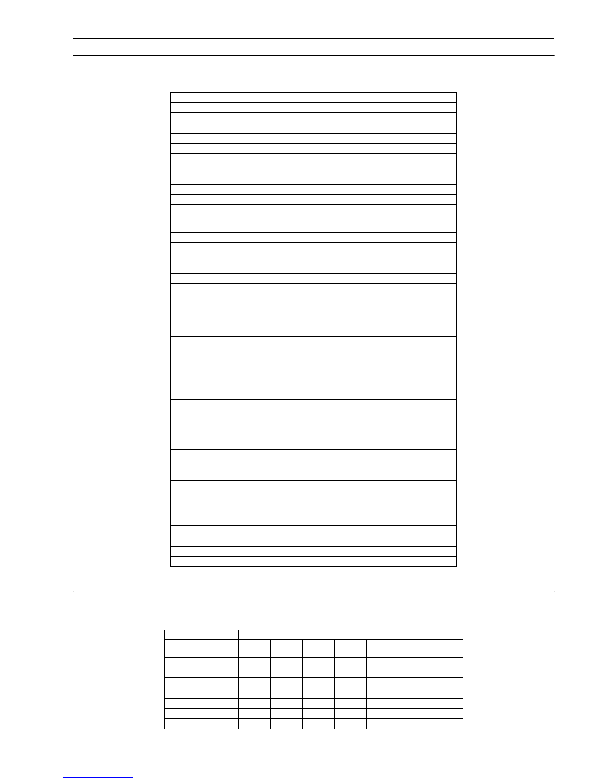
T-1-1
Body installation method Desktop
Exposure Method Semi-conductor laser
Development Method Toner projection
Transfer Method Roller transfer
Fixing method On-demand fixing
Delivery method Facedown /Faceup
Toner level detection function None
Toner supply type Toner cartridge replacement / Cartridge
Document type Sheet, 3D object (up to 2kg)
Maximum document size 216 x 297 mm
Scanning method CIS scanning method
Reproduction ratio 50 to 200%
Print area Print: 5 mm and more inner from paper egdes/ Copy: 2 mm and more
inner from paper egdes
Reading resolution 600 x 600 dpi
Copying resolution 600 x 600 dpi
Printing resolution 600 x 600 dpi
Print speed (A4) approx. 20 sheets/min
Print speed(LTR) approx. 21 sheets/min
Warm-up Time Approx. 8 sec. (temperature: 20 deg C, humidty: 65%; from when the
machine is plugged in untill the standby display appears)
: Warm-up time may differ depending on the condition and environment
of the machine.
First Print Time approx. 11 sec.
Cassette paper size A4, B5, A5, Letter, Legal, Executive, Envelope (DL, ISO-C5, COM10,
MONARCH)
Multi-purpose paper size A4, B5, A5, Letter, Legal, Executive, Envelope (DL, ISO-C5, COM10,
MONARCH)
Cassette paper type Plain paper (64 to 90g/m2), Heavy paper (105 to 128g/m2), Recycled
paper (64 to 80g/m2) Transparencyp, Envelope
Multi-purpose paper type Plain paper (64 to 90g/m2), Heavy paper (105 to 128g/m2), Recycled
paper (64 to 80g/m2) Transparencyp, Envelope
Cassette capacity Plain paper (64, 75, 80 g/m2): approx. 250 sheets, Heavy paper (90, 105
g/m2): approx. 200 sheets, Heavy paper H (128 g/m2): approx. 100
sheets, Transparency: approx. 100 sheets, Label: approx. 100 sheets,
Envelope: approx. 20 sheets
Multi-purpose capacity 1 sheet
Continuous reproduction 99 sheets
Energy save mode None
Operating environment
(Temperature range)
15 to 30 deg C
Operating environment
(Humidity range)
10 to 80 %RH
Power supply rating 230V, 50-60Hz
Power consumption (Maximum) approx. 780 W
Dimensions 449 mm x 539 mm x 369 mm
Weight approx. 11 kg (including cartridge)
Option None
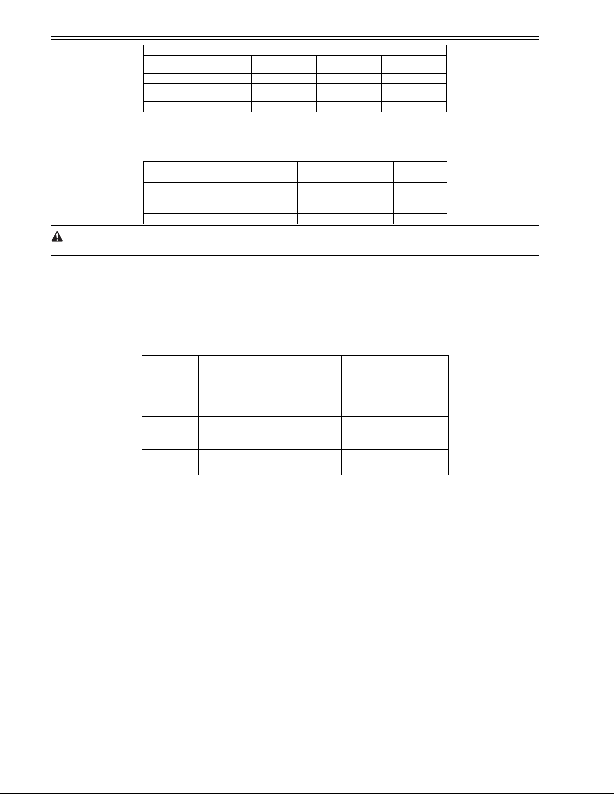
Fixing mode
Paper size Plain
paper
Plain
paper L
Heavy
paper
Heavy
paper H
Transpar
ency
Envelope COM10
A4 ( to 64 g/m2) 2020201220 - -
A4 (65 to 90 g/m2) - 18 10 8 18 - -
B5 (64 to 90 g/m2) 88448- -
A5 (64 to 90 g/m2) 88448 --
A4 (105 to 128 g/m2) - - 18 12 - - -
B5 (105 to 128 g/m2) - - 4 4 - - -
LTR (75 to 90 g/m2) 2121211221 - -
Chapter 1
1-2
(unit: sheets/min)
1.2.2 Stack Upon Delivery
0012-0849
T-1-2
The values herein are estimates only and are subject to change for product improvement.
1.2.3 System Requirements for Printer Driver
0012-0850
Operating System
Windows 98/98SE, Windows Me, Windows 2000 Professional, Windows XP
Computer
Any computer on whitch Windows 98, Windows Se, Windows Me, Windows 2000, or Windows XP runs properly.
Hardware Environment
-IBM or IBM-compatible PC
-CD-ROM drive or network environment with the access to CD-ROM
-PC equipped with a USB port and the USB class driver installed
T-1-3
*Log on as a user with adoministrator privileges is recommended.
1.3 Names of Parts
1.3.1 External View
0012-0851
<Front View>
LGL (75 to 90 g/m2)15------
LTR (Bond 75 to 90 g/m2,
105 g/m2)
--2112---
Envelope ------4
Paper type Face-down Face-up
Plain paper (64 to 90 g/m2) Approx. 60 sheets 1 sheet
Heavy paper (105 to 128 g/m2) Approx. 30 sheets 1 sheet
Transparency Approx. 10 sheets 1 sheet
Label Approx. 10 sheets 1 sheet
Envelope Approx. 10 sheets 1 sheet
OS CPU RAM Available Free Disk Space
Windows 98
Intel Pentium 90 MHz or
greater
32 MB of RAM, 64
MB or greater is
recommended
At least 115 MB, 200MB or greater is
recommended
Windows Me
Intel Pentium 150 MHz or
greater
32 MB of RAM, 64
MB or greater is
recommended
At least 115 MB, 200MB or greater is
recommended
Windows 2000*
Professional
Intel Pentium 133 MHz or
greater, or compatible micro
processors (up to 2
processors are supported)
64 MB of RAM, 128
MB or greater is
recommended
At least 115 MB, 200MB or greater is
recommended
Windows XP*
Pentium Family 300 MHz or
greater
64 MB of RAM, 128
MB or greater is
recommended
At least 115 MB, 200MB or greater is
recommended
Fixing mode
Paper size Plain
paper
Plain
paper L
Heavy
paper
Heavy
paper H
Transpar
ency
Envelope COM10

Chapter 1
1-3
F-1-1
T-1-4
<Rear View>
F-1-2
T-1-5
1.3.2 Operation panel
0012-0852
F-1-3
T-1-6
[1] Platen glass cover [5] Front cover
[2] Platen glass [6] Multi-purpose feeder
[3] Operation panel [7] Cassette
[4] Output tray
[1] USB port
[2] Face up cover
[3] Power socket
[4] Extension cover
[1] Practice/Memory [11] Collate/2on1/ key
[2] COPY Key [12] image Quality key
[1]
[2]
[3]
[4]
[5]
[6]
[7]
[1]
[2]
[3]
[4]
123
45
6
7
89
0
OK
[1]
[19] [18] [17] [16] [15][14][13][12] [11] [10]
[2] [3] [4] [5] [6] [7]
[8] [9]
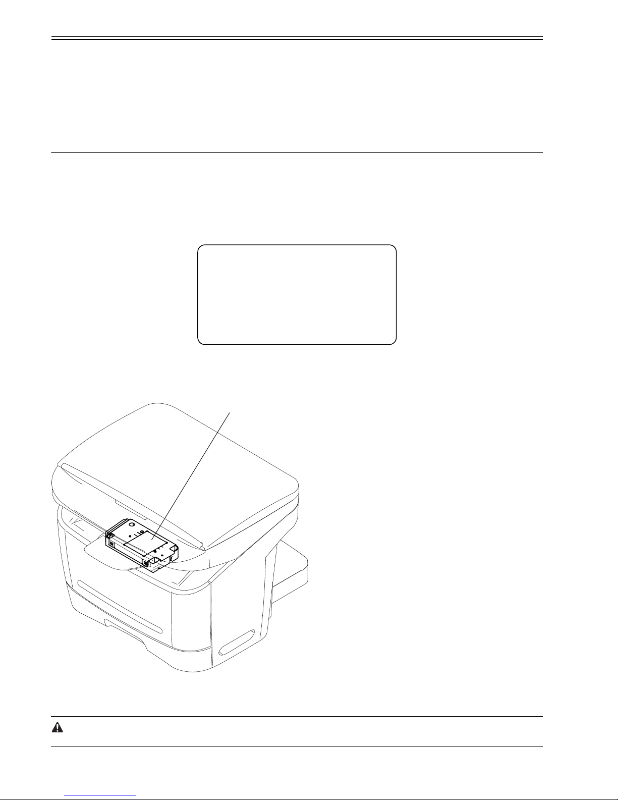
Chapter 1
1-4
1.4 Safety
1.4.1 Safety of Laser Light
0012-0864
Laser radiation could be hazardous to the human body. For this reason, laser radiation emitted inside this machine is hermetically sealed within the protective housing and external cover. No radiation can leaak from the machine in the normal operation of the product by the user.
1.4.2 Regulations Under the Center for Devices and Radiological Health (CDRH)
0012-0865
The CDRH of the US Food and Drug Administration put into effect regulations governing the sale of laser products in the US on August 2, 1976. These regulations
apply to all laser products produced on and after August 1, 1976, and a laser product cannot be sold unless it has been certified to comply with the regulations. The
following is the label used to indicate that the product has been certified under the regulations, and all laser products sold in the US must bear the label.
F-1-4
1.4.3 Handling the Laser Unit
0012-0866
The laser scanner unit emits invisible laser light inside it. If exposed to laser light, the human eye can irreparably be damaged. Never attempt to disassemble the
laser scanner unit. (It is not designed for servicing in the field). The covers around the laser scanner unit are identified by the following label [1].
F-1-5
1.4.4 Safety of Toner
0012-0867
The machine's toner is a non-toxic material composed of plastic, iron, and small amounts of dye.
Do not put the toner into fire. It may explode.
[3] SCAN Key [13] Clear key
[4] Error indicator [14] Initial setting/Registration
[5] Exposure key [15] (+) key
[6] Enlarge/Peduce key [16] OK key
[7] Numeric keys [17] (-) key
[8] Stop/Reset key [18] LCD
[9] Energy Saver key [19] Status Monitor key
[10] Start key
CANON
30-2, SHIMOMARUKO, 3-CHOME, OHTAKU, TOKYO,
146, JAPAN.
MANUFACTURED:
THIS PRODUCT CONFORMS WITH DHHS RADIATION
PERFORMANCE STANDARD 21CFR CHAPTER 1
SUBCHAPTER J.
[1]

Chapter 1
1-5
Toner on the Skin or Clothes
1. If your skin or clothes came into contact with toner, wash with water at once.
2. Do not use warm or hot water, which will cause the toner to jell, permanently fusing it with the fibers of the clothes.
3. Do not bring toner into contact with vinyl material. They are likely to react with each other.
1.4.5 Backup Battery
0012-3263
The machine's SCNT PCB are equipped with a lithium battery (1 pc. each) serving as a backup source of power in the event of a power shortage or when the power
plug is removed.
LISK OF EXPLOSION IF BATTERY IS REPLACED BY AN INCORRECT TYPE.
DISPOSE OF USED BATTERIES ACCORDING TO THE INSTRUCTIONS.


Chapter 2 TECHNICAL REFERENCE


Contents
Contents
2.1 Document Feed and Exposure System...........................................................................................................................2-1
2.1.1 Overview/Configuration .............................................................................................................................................................. 2-1
2.1.1.1 Overview .........................................................................................................................................................................................................2-1
2.2 Laser Exposure...............................................................................................................................................................2-2
2.2.1 Overview/Configuration .............................................................................................................................................................. 2-2
2.2.1.1 Overview .........................................................................................................................................................................................................2-2
2.3 Image Formation ............................................................................................................................................................2-3
2.3.1 Overview/Configuration .............................................................................................................................................................. 2-3
2.3.1.1 Overview .........................................................................................................................................................................................................2-3
2.4 Pickup and Feed System ................................................................................................................................................2-4
2.4.1 Overview/Configuration .............................................................................................................................................................. 2-4
2.4.1.1 Overview .........................................................................................................................................................................................................2-4
2.4.2 Other Control ............................................................................................................................................................................... 2-4
2.4.2.1 Manual Pickup Control ................................................................................................................................................................................... 2-4
2.4.2.2 Cassette Pickup Control ..................................................................................................................................................................................2-4
2.4.3 Detection Jams ............................................................................................................................................................................. 2-5
2.4.3.1 Jam Detection Outline..................................................................................................................................................................................... 2-5
2.4.3.1.1 Type so Jams ...........................................................................................................................................................................................2-5
2.4.3.2 Delay Jams ......................................................................................................................................................................................................2-5
2.4.3.2.1 Pickup Delay Jam ....................................................................................................................................................................................2-5
2.4.3.2.2 Delivery Delay Jam .................................................................................................................................................................................2-5
2.4.3.3 Stationary Jams ...............................................................................................................................................................................................2-5
2.4.3.3.1 Pickup Stationary Jam .............................................................................................................................................................................2-5
2.4.3.3.2 Delivery Stationary Jam ..........................................................................................................................................................................2-5
2.4.3.4 Other Jams.......................................................................................................................................................................................................2-5
2.4.3.4.1 Wrap Jam.................................................................................................................................................................................................2-5
2.4.3.4.2 Initial Jam................................................................................................................................................................................................2-5
2.4.3.4.3 Cover Open Jam ......................................................................................................................................................................................2-5
2.5 Fixing Unit .....................................................................................................................................................................2-6
2.5.1 Overview/Configuration .............................................................................................................................................................. 2-6
2.5.1.1 Overview .........................................................................................................................................................................................................2-6
2.5.2 Protection Function ...................................................................................................................................................................... 2-6
2.5.2.1 Protective Mechanisms ...................................................................................................................................................................................2-6
2.5.2.2 Detecting a Fault in the Fixing Assembly....................................................................................................................................................... 2-6
2.6 External and Controls.....................................................................................................................................................2-7
2.6.1 Power Supply ............................................................................................................................................................................... 2-7
2.6.1.1 Backup Battery ................................................................................................................................................................................................2-7
2.6.1.1.1 Backup Battery ........................................................................................................................................................................................2-7


Chapter 2
2-1
2.1 Document Feed and Exposure System
2.1.1 Overview/Configuration
2.1.1.1 Overview
0012-0870
F-2-1
T-2-1
The CIS unit driven by the flatbed motor reads out image data of a document on the platen glass.
[1] CIS unit
[2] Flatbed motor
[2] [1]
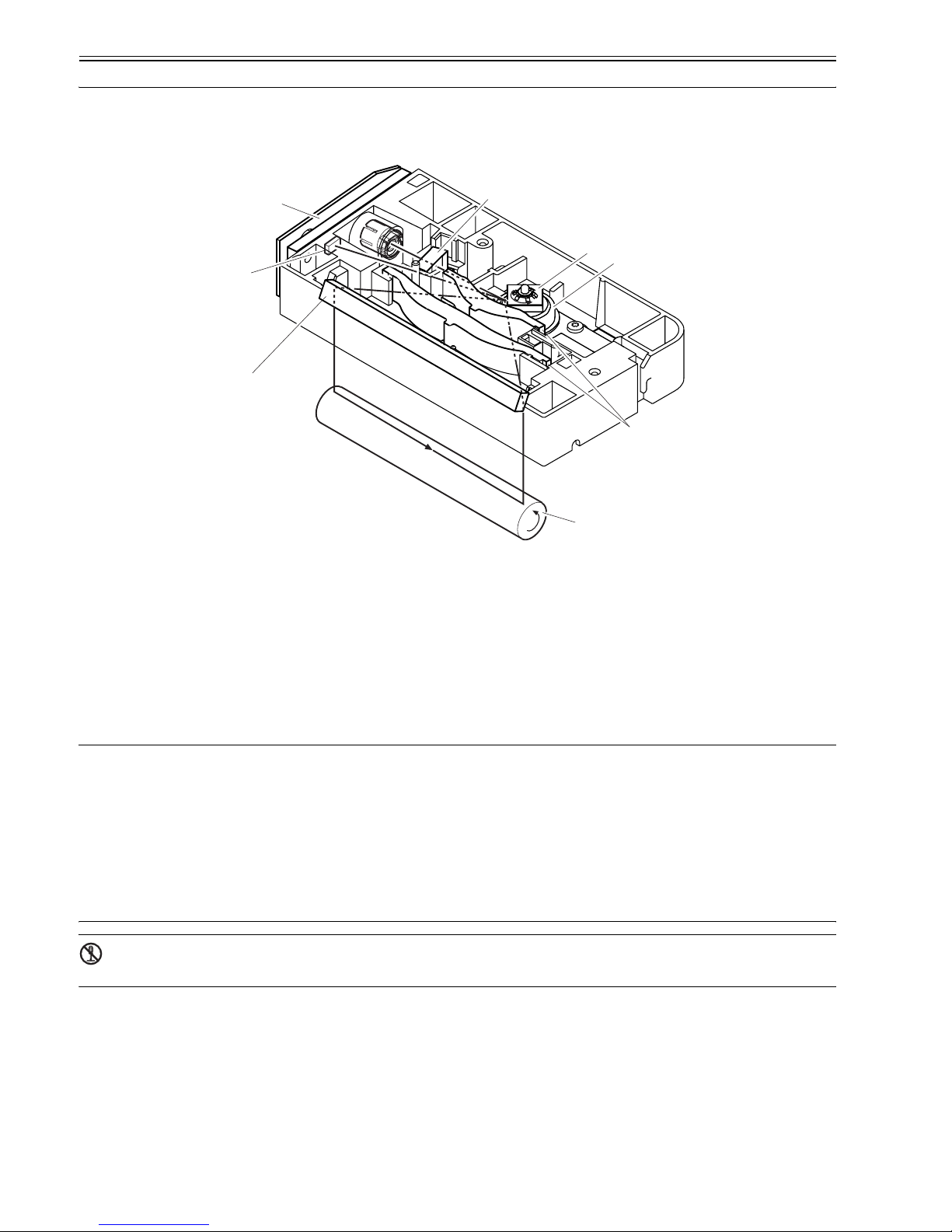
Chapter 2
2-2
2.2 Laser Exposure
2.2.1 Overview/Configuration
2.2.1.1 Overview
0012-0873
F-2-2
T-2-2
The machine's laser scanner assembly consists of the laser driver and the scanner motor, which are driven by signals coming from the engine controller.
The laser driver serves to turn on the laser diode according to the laser control signal and video signals from the engine controller.
The laser beam moves thorough the collimator less and the cylindrical lens to reach the 4-facet mirror rotating at a specific speed.
The leaser beam reflected by the 4-facet mirror moves through the imaging lens arranged in front of the 4-facet mirror and the reflecting mirror to reach and focus
on the photosensitive drum.
When the 4-facet mirror rotates at a specific speed, the laser beam scans the photosensitive drum in keeping with the mirror rotation, thus drawing static images on
the photosensitive drum.
MEMO:
BD Fault
The machine identifies a BD fault if it does not detect the /BDI signal within 0.1 sec after the scanner motor is forced to accelerate. It also detects a BD fault
if it does not detect a specific interval of /BDI signals for 2 sec continuously after the scanner motor has reached a specific revolution (number of rotations).
Scanner Fault
If the machine does not detect the /BDI signal 1.4 sc after it has stopped forcing the scanner motor to accelerate, it extends the period of detection by 120 sec;
if it still does not detect a specific interval of /BDI signals, it identifies a scanner fault.
BD Error
The machine identifies a BD error if it does not detect the /BDI signal at a specific interval while the /BDI signal is being generated. It, however, does not
identify a BD error under the following condition:
-the door is identified as being open within 0.2 sec after detection of a BD error.
-a BD fault or a scanner fault is detected after a BD error has been identified.
The laser/scanner unit contains parts that cannot be adjusted in the field. Do not attempt to disassemble the laser/scanner unit.
[1] Laser driver PCB [5] Imaging lends
[2] BD sensor [6] Scanner motor
[3] Reflecting mirror [7] 4-facet mirror
[4] Photosensitive drum [8] Cylindrical lens
[2]
[1]
[3]
[4]
[5]
[7]
[6]
[8]
 Loading...