


 Loading...
MF6600/D1100 Series
Service Manual
Product Overview
Technical Overview
Periodical Services
Disassembly/Assembly
Adjustment
Trouble Shooting
Error Codes
Service Mode
1 2 3 4 5 6 7 8
F-0-1
Appendex

0
Application
This manual has been issued by Canon Inc. for qualified persons to learn technical theory, installation, maintenance, and repair of products. This manual covers all localities where the products are sold. For this reason, there may be information in this manual that does not apply to your locality.
Corrections
This manual may contain technical inaccuracies or typographical errors due to improvements or changes in products. When changes occur in applicable products or in the contents of this manual, Canon will release technical information as the need arises. In the event of major changes in the contents of this manual over a long or short period, Canon will issue a new edition of this manual.
The following paragraph does not apply to any countries where such provisions are inconsistent with local law.
0-2
of this manual.
The following paragraph does not apply to any countries where such provisions are inconsistent with local law.
Trademarks
The product names and company names used in this manual are the registered trademarks of the individual companies.
Copyright
This manual is copyrighted with all rights reserved. Under the copyright laws, this manual may not be copied, reproduced or
translated into another language, in whole or in part, without the written consent of Canon Inc.
(C) CANON INC. 2009
Caution
Use of this manual should be strictly supervised to avoid disclosure of confidential information.
0-2
0
0
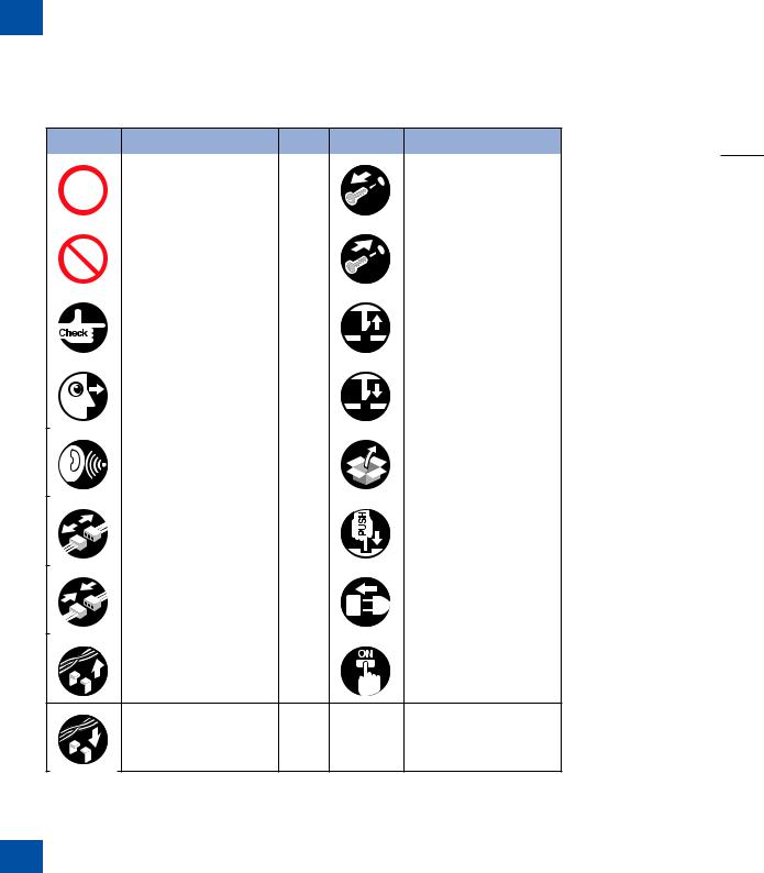
Explanation of Symbols
The following symbols are used throughout this Service Manual.
Symbols |
Explanation |
Symbols |
Explanation |
||
|
|
|
|
|
|
|
Used to show permission. |
|
|
|
Remove the screw. |
|
|
|
|
|
|
|
Used to show prohibition. |
|
|
|
Tighten the screw. |
|
|
|
|
|
|
|
Check. |
|
|
|
Remove the claw. |
|
|
|
|
|
|
|
Check visually. |
|
|
|
Insert the claw. |
|
|
|
|
|
|
|
Check the noise. |
|
|
|
Use the bundled part. |
|
|
|
|
|
|
|
Disconnect the connector. |
|
|
|
Push the part. |
|
|
|
|
|
|
|
Connect the connector. |
|
|
|
Plug the power cable. |
|
|
|
|
||
|
|
|
|
|
|
|
|
|
|
|
|
|
Remove the cable/wire |
|
|
|
|
|
from the cable guide or wire |
|
|
|
Turn on the power. |
|
saddle. |
|
|
|
|
Set the cable/wire to the cable guide or wire saddle.
T-0-1
0-3
The following rules apply throughout this Service Manual:
1.Each chapter contains sections explaining the purpose of specific functions and the relationship between electrical and mechanical systems with reference to the timing of operation.
In the diagrams,  represents the path of mechanical drive; where a signal name accompanies the symbol, the arrow
  indicates the direction of the electric signal.
The expression "turn on the power" means flipping on the power switch, closing the front door, and closing the delivery unit door, which results in supplying the machine with power.
2.In the digital circuits, '1' is used to indicate that the voltage level of a given signal is "High", while '0' is used to indicate "Low". (The voltage value, however, differs from circuit to circuit.) In addition, the asterisk (*) as in "DRMD*" indicates that the DRMD signal goes on
when '0'.
In practically all cases, the internal mechanisms of a microprocessor cannot be checked in the field. Therefore, the operations of the microprocessors used in the machines are not discussed: they are explained in terms of from sensors to the input of the DC controller
PCB and from the output of the DC controller PCB to the loads.
The descriptions in this Service Manual are subject to change without notice for product improvement or other purposes, and major changes will be communicated in the form of
Service Information bulletins.
All service persons are expected to have a good understanding of the contents of this Service Manual and all relevant Service Information bulletins and be able to identify and isolate faults in the machine.
0-3
0

0
Contents
Safety Precautions
CDRH Provisions-------------------------------------------------------------- |
0-2 |
Laser Safety--------------------------------------------------------------------- |
0-2 |
About Laser Beams---------------------------------------------------------------- |
0-2 |
Handling Laser Scanner Unit---------------------------------------------------- |
0-2 |
Toner Safety--------------------------------------------------------------------- |
0-3 |
About Toner-------------------------------------------------------------------------- |
0-3 |
Handling Adhered Toner---------------------------------------------------------- |
0-3 |
Notes When Handling A Battery------------------------------------------- |
0-3 |
Notes On Assembly/Disassembly----------------------------------------- |
0-3 |
Product Overview
Product Lineups---------------------------------------------------------------- |
1-2 |
Main Unit------------------------------------------------------------------------------ |
1-2 |
Options-------------------------------------------------------------------------------- |
1-3 |
Product Features-------------------------------------------------------------- |
1-3 |
Features------------------------------------------------------------------------------ |
1-3 |
Compact MFP-------------------------------------------------------------------------------- |
1-3 |
High-speed MFP----------------------------------------------------------------------------- |
1-3 |
Power-saving MFP-------------------------------------------------------------------------- |
1-3 |
Specifications------------------------------------------------------------------- |
1-4 |
Main Unit Specifications---------------------------------------------------------- |
1-4 |
ADF Specifications----------------------------------------------------------------- |
1-5 |
FAX Specifications----------------------------------------------------------------- |
1-5 |
Print Speed.-------------------------------------------------------------------------- |
1-6 |
Paper types-------------------------------------------------------------------------- |
1-6 |
Paper size---------------------------------------------------------------------------- |
1-7 |
Name of Parts------------------------------------------------------------------ |
1-7 |
External View------------------------------------------------------------------------ |
1-7 |
Front Side------------------------------------------------------------------------------------- |
1-7 |
Rear Side-------------------------------------------------------------------------------------- |
1-8 |
|
0-1 |
Cross Sectional View-------------------------------------------------------------- |
1-9 |
ADF/Reader Unit---------------------------------------------------------------------------- |
1-9 |
Printer------------------------------------------------------------------------------------------ |
1-9 |
Operation Panel-------------------------------------------------------------------- |
1-10 |
Main Operation Panel--------------------------------------------------------------------- |
1-10 |
Send Operation Panel--------------------------------------------------------------------- |
1-10 |
Function List------------------------------------------------------------------------ |
1-11 |
Copy Area------------------------------------------------------------------------------------ |
1-11 |
Reception Print Area----------------------------------------------------------------------- |
1-11 |
BDL Print Area------------------------------------------------------------------------------ |
1-11 |
PCL Print Area------------------------------------------------------------------------------ |
1-11 |
Operation Environment of the Printer Driver-------------------------------- |
1-11 |
Operation environment-------------------------------------------------------------------- |
1-11 |
Hardware environment-------------------------------------------------------------------- |
1-11 |
Network Specifications-------------------------------------------------------------------- |
1-11 |
SEND Specifications---------------------------------------------------------------------- |
1-12 |
Technical Overview |
|
Basic Configuration----------------------------------------------------------- |
2-2 |
Configuration Function------------------------------------------------------------ |
2-2 |
Basic Sequence--------------------------------------------------------------------- |
2-2 |
Basic Operational Sequence------------------------------------------------------------- |
2-2 |
Print Sequence------------------------------------------------------------------------------- |
2-3 |
Print Mode---------------------------------------------------------------------------- |
2-4 |
Document Exposure/feeder System-------------------------------------- |
2-5 |
Document Exposure System---------------------------------------------------- |
2-5 |
Specifications / Control / Function List |
|
Major Components-------------------------------------------------------------------------- |
2-5 |
Document Feeder System------------------------------------------------------- |
2-6 |
Pickup/Feed/Delivery Operation--------------------------------------------------------- |
2-6 |
Original Detection--------------------------------------------------------------------------- |
2-7 |
Jam Detection-------------------------------------------------------------------------------- |
2-8 |
Service Tasks------------------------------------------------------------------------ |
2-8 |
Action for Parts Replacement------------------------------------------------------------ |
2-8 |
Maintenance---------------------------------------------------------------------------------- |
2-8 |
Service Notes-------------------------------------------------------------------------------- |
2-8 |
Engine Control System------------------------------------------------------- |
2-9 |
|
0-1 |
0

0
Outline--------------------------------------------------------------------------------- |
2-9 |
Controls------------------------------------------------------------------------------- |
2-9 |
Outline------------------------------------------------------------------------------------------ |
2-9 |
Motor Control-------------------------------------------------------------------------------- |
2-10 |
Fan Control---------------------------------------------------------------------------------- |
2-11 |
Failure Detection--------------------------------------------------------------------------- |
2-11 |
Low-voltage Power Supply------------------------------------------------------ |
2-12 |
Outline----------------------------------------------------------------------------------------- |
2-12 |
Protective Function------------------------------------------------------------------------ |
2-13 |
Safety------------------------------------------------------------------------------------------ |
2-13 |
Low-voltage Power Supply Unit Failure Detection--------------------------------- |
2-13 |
Power-Saving Mode----------------------------------------------------------------------- |
2-13 |
Service Tasks----------------------------------------------------------------------- |
2-14 |
Action for Parts Replacement----------------------------------------------------------- |
2-14 |
Maintenance--------------------------------------------------------------------------------- |
2-14 |
Service Notes------------------------------------------------------------------------------- |
2-14 |
Laser Scanner System----------------------------------------------------- |
2-15 |
Outline-------------------------------------------------------------------------------- |
2-15 |
Optical Unit Failure Detection-------------------------------------------------- |
2-15 |
Service Tasks----------------------------------------------------------------------- |
2-15 |
Action for Parts Replacement----------------------------------------------------------- |
2-15 |
Maintenance--------------------------------------------------------------------------------- |
2-15 |
Service Notes------------------------------------------------------------------------------- |
2-15 |
Image-formation System--------------------------------------------------- |
2-16 |
Outline-------------------------------------------------------------------------------- |
2-16 |
Image-formation Process-------------------------------------------------------- |
2-16 |
Outline----------------------------------------------------------------------------------------- |
2-16 |
Latent Image Formation Block---------------------------------------------------------- |
2-17 |
Developing Block--------------------------------------------------------------------------- |
2-17 |
Transfer Block------------------------------------------------------------------------------- |
2-18 |
Fixing Block---------------------------------------------------------------------------------- |
2-18 |
Drum Cleaning Block---------------------------------------------------------------------- |
2-18 |
High-voltage Power Supply----------------------------------------------------- |
2-19 |
Outline----------------------------------------------------------------------------------------- |
2-19 |
Service Tasks----------------------------------------------------------------------- |
2-19 |
Action for Parts Replacement----------------------------------------------------------- |
2-19 |
Maintenance--------------------------------------------------------------------------------- |
2-19 |
Notes on Field Service-------------------------------------------------------------------- |
2-19 |
|
0-2 |
Fixing Unit System---------------------------------------------------------- |
2-20 |
Outline-------------------------------------------------------------------------------- |
2-20 |
Fixing Control Circuit------------------------------------------------------------- |
2-21 |
Throughput Reduction Control---------------------------------------------------------- |
2-21 |
Fixing Temperature Control-------------------------------------------------------------- |
2-22 |
Protective Function------------------------------------------------------------------------ |
2-23 |
Failure Detection--------------------------------------------------------------------------- |
2-23 |
Service Tasks----------------------------------------------------------------------- |
2-24 |
At Parts Replacement--------------------------------------------------------------------- |
2-24 |
Maintenance--------------------------------------------------------------------------------- |
2-24 |
Notes On Service Works----------------------------------------------------------------- |
2-24 |
Media Feed System--------------------------------------------------------- |
2-25 |
Outline-------------------------------------------------------------------------------- |
2-25 |
Drive Configuration---------------------------------------------------------------- |
2-25 |
Jam Detection---------------------------------------------------------------------- |
2-26 |
Outline----------------------------------------------------------------------------------------- |
2-26 |
Pickup Delay Jam-------------------------------------------------------------------------- |
2-27 |
Pickup Stationary Jam-------------------------------------------------------------------- |
2-27 |
Delivery Delay Jam------------------------------------------------------------------------ |
2-27 |
Delivery Stationary Jam------------------------------------------------------------------ |
2-27 |
Fixing Paper Wrap Jam ------------------------------------------------------------------ |
2-27 |
Reverse Delay Jam------------------------------------------------------------------------ |
2-27 |
Reverse Stationary Jam------------------------------------------------------------------ |
2-27 |
Internal Residual Jam--------------------------------------------------------------------- |
2-27 |
Door Open Jam----------------------------------------------------------------------------- |
2-27 |
Service Tasks----------------------------------------------------------------------- |
2-27 |
At Parts Replacement--------------------------------------------------------------------- |
2-27 |
Maintenance--------------------------------------------------------------------------------- |
2-27 |
Notes On Service Works----------------------------------------------------------------- |
2-27 |
Periodical Services |
|
Periodically Replaced Parts------------------------------------------------- |
3-2 |
Periodically Replaced Parts------------------------------------------------------ |
3-2 |
Consumables Expected Replacement Timing------------------------------ |
3-2 |
Consumable Parts------------------------------------------------------------- |
3-2 |
Durables Replaced by the User------------------------------------------------- |
3-2 |
Durables Replaced by the Service Person----------------------------------- |
3-2 |
|
0-2 |
0

0
Periodical Service------------------------------------------------------------- |
3-2 |
Periodical Service------------------------------------------------------------------ |
3-2 |
Cleaning-------------------------------------------------------------------------- |
3-2 |
Cleaning at Service Visit---------------------------------------------------------- |
3-2 |
Cleaning Method (External Covers)---------------------------------------------------- |
3-3 |
Cleaning Method (Scanning Area)------------------------------------------------------ |
3-3 |
Cleaning Method (ADF)-------------------------------------------------------------------- |
3-3 |
Fixing unit------------------------------------------------------------------------------------- |
3-4 |
Disassembly/Assembly
PREFACE----------------------------------------------------------------------- |
4-2 |
Outline--------------------------------------------------------------------------------- |
4-2 |
List of Parts---------------------------------------------------------------------- |
4-3 |
External View------------------------------------------------------------------------ |
4-3 |
Front Side------------------------------------------------------------------------------------- |
4-3 |
Rear Side-------------------------------------------------------------------------------------- |
4-4 |
Main Unit------------------------------------------------------------------------------ |
4-5 |
Main Parts---------------------------------------------------------------------------- |
4-6 |
Sensor / Switc-------------------------------------------------------------------------------- |
4-6 |
Motor / Fan------------------------------------------------------------------------------------ |
4-7 |
Other-------------------------------------------------------------------------------------------- |
4-8 |
PCB--------------------------------------------------------------------------------------------- |
4-9 |
Connector Layout Drawing (TAYPE I)---------------------------------------- |
4-10 |
Internal 1-------------------------------------------------------------------------------------- |
4-10 |
Internal 2-------------------------------------------------------------------------------------- |
4-12 |
Connector Layout Drawing (TAYPE II)--------------------------------------- |
4-14 |
Internal 1-------------------------------------------------------------------------------------- |
4-14 |
Internal 2-------------------------------------------------------------------------------------- |
4-16 |
External Cover, Internal Cover------------------------------------------- |
4-18 |
External View----------------------------------------------------------------------- |
4-18 |
Front Side------------------------------------------------------------------------------------ |
4-18 |
Rear Side------------------------------------------------------------------------------------- |
4-19 |
Removing the Left Cover-------------------------------------------------------- |
4-19 |
Procedure------------------------------------------------------------------------------------ |
4-19 |
Removing the Left Rear Cover------------------------------------------------- |
4-22 |
Preparations--------------------------------------------------------------------------------- |
4-22 |
Procedure------------------------------------------------------------------------------------ |
4-22 |
|
0-3 |
Removing the Right Cover------------------------------------------------------ |
4-23 |
Procedure------------------------------------------------------------------------------------ |
4-23 |
Removing the Right Rear Cover----------------------------------------------- |
4-26 |
Preparations--------------------------------------------------------------------------------- |
4-26 |
Procedure------------------------------------------------------------------------------------ |
4-26 |
Removing the Front Cover------------------------------------------------------ |
4-26 |
Preparations--------------------------------------------------------------------------------- |
4-26 |
Procedure------------------------------------------------------------------------------------ |
4-26 |
Removing the Rear Cover Unit------------------------------------------------ |
4-27 |
Preparations--------------------------------------------------------------------------------- |
4-27 |
Procedure------------------------------------------------------------------------------------ |
4-27 |
Removing the Upper Cover Unit----------------------------------------------- |
4-28 |
Preparations--------------------------------------------------------------------------------- |
4-28 |
Procedure------------------------------------------------------------------------------------ |
4-28 |
Document Exposure, Feed System------------------------------------- |
4-30 |
Location------------------------------------------------------------------------------ |
4-30 |
Removing the ADF Unit---------------------------------------------------------- |
4-30 |
Procedure------------------------------------------------------------------------------------ |
4-30 |
Removing the ADF Unit + Reader Unit-------------------------------------- |
4-33 |
Preparations--------------------------------------------------------------------------------- |
4-33 |
Procedure------------------------------------------------------------------------------------ |
4-33 |
Separating the ADF Unit + Reader Unit------------------------------------- |
4-35 |
Preparations--------------------------------------------------------------------------------- |
4-35 |
Procedure------------------------------------------------------------------------------------ |
4-35 |
Removing the ADF Roller Unit------------------------------------------------- |
4-37 |
Procedure------------------------------------------------------------------------------------ |
4-37 |
Removing the ADF Pickup Roller---------------------------------------------- |
4-38 |
Preparations--------------------------------------------------------------------------------- |
4-38 |
Procedure------------------------------------------------------------------------------------ |
4-38 |
Removing the ADF Separation Roller---------------------------------------- |
4-39 |
Preparations--------------------------------------------------------------------------------- |
4-39 |
Procedure------------------------------------------------------------------------------------ |
4-39 |
Removing the ADF Separation Pad------------------------------------------- |
4-41 |
Procedure------------------------------------------------------------------------------------ |
4-41 |
Removing the ADF Pickup Feed Unit---------------------------------------- |
4-42 |
Procedure------------------------------------------------------------------------------------ |
4-42 |
Removing the ADF Pickup Motor Unit---------------------------------------- |
4-45 |
|
0-3 |
0

0
Preparations--------------------------------------------------------------------------------- |
4-45 |
Procedure------------------------------------------------------------------------------------ |
4-45 |
Removing the ADF Delivery Solenoid Unit---------------------------------- |
4-46 |
Preparations--------------------------------------------------------------------------------- |
4-46 |
Procedure------------------------------------------------------------------------------------ |
4-46 |
Removing the Reader Unit Upper Cover------------------------------------ |
4-46 |
Preparations--------------------------------------------------------------------------------- |
4-46 |
Procedure------------------------------------------------------------------------------------ |
4-46 |
Removing the CIS Unit----------------------------------------------------------- |
4-48 |
Preparations--------------------------------------------------------------------------------- |
4-48 |
Procedure------------------------------------------------------------------------------------ |
4-48 |
Removing the Reader Motor Unit--------------------------------------------- |
4-51 |
Preparations--------------------------------------------------------------------------------- |
4-51 |
Procedure------------------------------------------------------------------------------------ |
4-51 |
Controller System------------------------------------------------------------ |
4-53 |
Location1---------------------------------------------------------------------------- |
4-53 |
Location2---------------------------------------------------------------------------- |
4-54 |
Removing the Controller Cover------------------------------------------------ |
4-55 |
Preparations--------------------------------------------------------------------------------- |
4-55 |
Procedure------------------------------------------------------------------------------------ |
4-55 |
Removing the ADF/Reader Driver PCB-------------------------------------- |
4-55 |
Preparations--------------------------------------------------------------------------------- |
4-55 |
Procedure------------------------------------------------------------------------------------ |
4-55 |
Removing the Main Controller Board----------------------------------------- |
4-56 |
Preparations--------------------------------------------------------------------------------- |
4-56 |
Procedure (TYPE I)------------------------------------------------------------------------ |
4-56 |
Procedure (TYPE II)----------------------------------------------------------------------- |
4-57 |
Removing the NCU PCB-------------------------------------------------------- |
4-58 |
Preparations--------------------------------------------------------------------------------- |
4-58 |
Procedure------------------------------------------------------------------------------------ |
4-58 |
Removing the Capacitor PCB-------------------------------------------------- |
4-59 |
Preparations--------------------------------------------------------------------------------- |
4-59 |
Procedure------------------------------------------------------------------------------------ |
4-59 |
Removing the All-night Power PCB Mount (TYPE I)--------------------- |
4-59 |
Preparations--------------------------------------------------------------------------------- |
4-59 |
Procedure------------------------------------------------------------------------------------ |
4-59 |
Removing the All-night Power PCB (TYPE I)------------------------------- |
4-60 |
Preparations--------------------------------------------------------------------------------- |
4-60 |
|
0-4 |
Procedure------------------------------------------------------------------------------------ |
4-60 |
Removing the Power PCB (TYPE I)------------------------------------------ |
4-60 |
Preparations--------------------------------------------------------------------------------- |
4-60 |
Procedure------------------------------------------------------------------------------------ |
4-60 |
Removing the Controller Box (TYPE I)--------------------------------------- |
4-61 |
Preparations--------------------------------------------------------------------------------- |
4-61 |
Procedure------------------------------------------------------------------------------------ |
4-61 |
Removing the Controller Box (TYPE II)-------------------------------------- |
4-62 |
Preparations--------------------------------------------------------------------------------- |
4-62 |
Procedure------------------------------------------------------------------------------------ |
4-62 |
Removing the Engine Controller Unit (TYPE I)---------------------------- |
4-64 |
Preparations--------------------------------------------------------------------------------- |
4-64 |
Procedure------------------------------------------------------------------------------------ |
4-64 |
Removing the Engine Controller Unit (TYPE II)--------------------------- |
4-67 |
Preparations--------------------------------------------------------------------------------- |
4-67 |
Procedure------------------------------------------------------------------------------------ |
4-67 |
Removing the Control Panel---------------------------------------------------- |
4-70 |
Removing the Main Motor (TYPE I)------------------------------------------- |
4-71 |
Preparations--------------------------------------------------------------------------------- |
4-71 |
Procedure------------------------------------------------------------------------------------ |
4-71 |
Removing the Main Motor (TYPE II)------------------------------------------ |
4-73 |
Preparations--------------------------------------------------------------------------------- |
4-73 |
Procedure------------------------------------------------------------------------------------ |
4-73 |
Removing the Main Fan--------------------------------------------------------- |
4-75 |
Preparations--------------------------------------------------------------------------------- |
4-75 |
Procedure------------------------------------------------------------------------------------ |
4-75 |
Removing the Power Cooling Fan-------------------------------------------- |
4-75 |
Preparations--------------------------------------------------------------------------------- |
4-75 |
Procedure------------------------------------------------------------------------------------ |
4-76 |
Removing the Controller Fan (TYPE I)--------------------------------------- |
4-77 |
Preparations--------------------------------------------------------------------------------- |
4-77 |
Procedure------------------------------------------------------------------------------------ |
4-77 |
Removing the Main Drive Unit (TYPE I)------------------------------------- |
4-77 |
Preparations--------------------------------------------------------------------------------- |
4-77 |
Procedure------------------------------------------------------------------------------------ |
4-77 |
Removing the Main Drive Unit (TYPE II)------------------------------------ |
4-81 |
Preparations--------------------------------------------------------------------------------- |
4-81 |
Procedure------------------------------------------------------------------------------------ |
4-81 |
|
0-4 |
0

0
Removing the Duplex Drive Unit (TYPE I)---------------------------------- |
4-84 |
Preparations--------------------------------------------------------------------------------- |
4-84 |
Procedure------------------------------------------------------------------------------------ |
4-84 |
Removing the Duplex Drive Unit (TYPE II)--------------------------------- |
4-86 |
Preparations--------------------------------------------------------------------------------- |
4-86 |
Procedure------------------------------------------------------------------------------------ |
4-86 |
Removing the Manual Tray Pickup Solenoid (TYPE I)------------------- |
4-88 |
Preparations--------------------------------------------------------------------------------- |
4-88 |
Procedure------------------------------------------------------------------------------------ |
4-88 |
Removing the Manual Tray Pickup Solenoid (TYPE II)------------------ |
4-89 |
Preparations--------------------------------------------------------------------------------- |
4-89 |
Procedure------------------------------------------------------------------------------------ |
4-89 |
Removing the Duplex Reverse Solenoid------------------------------------ |
4-90 |
Preparations--------------------------------------------------------------------------------- |
4-90 |
Procedure------------------------------------------------------------------------------------ |
4-90 |
Removing the Cassette Pickup Solenoid------------------------------------ |
4-90 |
Preparations--------------------------------------------------------------------------------- |
4-90 |
Procedure------------------------------------------------------------------------------------ |
4-90 |
Removing the Speaker (TYPE I)---------------------------------------------- |
4-91 |
Preparations--------------------------------------------------------------------------------- |
4-91 |
Procedure------------------------------------------------------------------------------------ |
4-91 |
Removing the Speaker (TYPE II)---------------------------------------------- |
4-92 |
Preparations--------------------------------------------------------------------------------- |
4-92 |
Procedure------------------------------------------------------------------------------------ |
4-92 |
Laser Exposure System---------------------------------------------------- |
4-93 |
Location------------------------------------------------------------------------------ |
4-93 |
Removing the Laser Scanner Unit-------------------------------------------- |
4-93 |
Preparations--------------------------------------------------------------------------------- |
4-93 |
Procedure------------------------------------------------------------------------------------ |
4-93 |
Image Forming System---------------------------------------------------- |
4-95 |
Location------------------------------------------------------------------------------ |
4-95 |
Removing the Transfer Roller-------------------------------------------------- |
4-95 |
Removing the Registration Unit------------------------------------------------ |
4-96 |
Preparations (TYPE I)--------------------------------------------------------------------- |
4-96 |
Preparations (TYPE II)-------------------------------------------------------------------- |
4-96 |
Procedure------------------------------------------------------------------------------------ |
4-96 |
Fixing System----------------------------------------------------------------- |
4-98 |
|
0-5 |
Location------------------------------------------------------------------------------ |
4-98 |
Removing the Fixing Unit-------------------------------------------------------- |
4-98 |
Preparations--------------------------------------------------------------------------------- |
4-98 |
Procedure (TYPE I)------------------------------------------------------------------------ |
4-98 |
Procedure (TYPE II)--------------------------------------------------------------------- |
4-101 |
Paper Feed/Transport/Output System-------------------------------- |
4-104 |
Location---------------------------------------------------------------------------- |
4-104 |
Removing the Duplex Feed Unit--------------------------------------------- |
4-105 |
Preparations------------------------------------------------------------------------------- |
4-105 |
Procedure---------------------------------------------------------------------------------- |
4-105 |
Removing the Cassette Pickup Roller-------------------------------------- |
4-107 |
Removing the Cassette Separation Pad----------------------------------- |
4-108 |
Removing the Multi-purpose Pickup Roller------------------------------- |
4-108 |
Removing the Multi-purpose Separation Pad---------------------------- |
4-109 |
Adjustment |
|
Scanning System Adjustment---------------------------------------------- |
5-2 |
Procedure After Replacing the Reader Scanner Unit (the Contact |
|
Sensor)-------------------------------------------------------------------------------- |
5-2 |
Procedure After Replacing the Copyboard Glass-------------------------- |
5-2 |
Procedure After Replacing the Reader Unit--------------------------------- |
5-2 |
Procedure After Replacing the ADF Unit------------------------------------- |
5-2 |
Electrical Adjustment---------------------------------------------------------- |
5-3 |
Procedure After Replacing the Main Controller Board-------------------- |
5-3 |
Trouble Shooting |
|
Test Print------------------------------------------------------------------------- |
6-2 |
Test Pages--------------------------------------------------------------------------- |
6-2 |
Engine-test Page---------------------------------------------------------------------------- |
6-2 |
Controller Test Print ------------------------------------------------------------------------ |
6-2 |
Trouble Shooting Items------------------------------------------------------- |
6-3 |
Image Defects----------------------------------------------------------------------- |
6-3 |
Light Print-------------------------------------------------------------------------------------- |
6-3 |
Dark Print-------------------------------------------------------------------------------------- |
6-3 |
Completely Blank---------------------------------------------------------------------------- |
6-4 |
All Black---------------------------------------------------------------------------------------- |
6-4 |
|
0-5 |
0

0
White Spots----------------------------------------------------------------------------------- |
6-4 |
Dirt On Back---------------------------------------------------------------------------------- |
6-5 |
Vertical Lines--------------------------------------------------------------------------------- |
6-5 |
Horizontal Lines------------------------------------------------------------------------------ |
6-5 |
Dirt On Front---------------------------------------------------------------------------------- |
6-6 |
Dropouts--------------------------------------------------------------------------------------- |
6-6 |
Vertical White Lines------------------------------------------------------------------------- |
6-6 |
Horizontal White Lines--------------------------------------------------------------------- |
6-7 |
Loose Toner----------------------------------------------------------------------------------- |
6-7 |
Misformed Image---------------------------------------------------------------------------- |
6-8 |
Repetitive Image Defects Ruler---------------------------------------------------------- |
6-8 |
Adjustment of Fixing System---------------------------------------------------- |
6-8 |
Nip-width Specifications------------------------------------------------------------------- |
6-8 |
Version Up----------------------------------------------------------------------- |
6-9 |
Overview------------------------------------------------------------------------------ |
6-9 |
Overview of Upgrading--------------------------------------------------------------------- |
6-9 |
Preparation--------------------------------------------------------------------------- |
6-9 |
Necessary System Environment-------------------------------------------------------- |
6-9 |
Before Downloading the System Software------------------------------------------ |
6-10 |
Downloading the System Software------------------------------------------- |
6-10 |
Downloading the System----------------------------------------------------------------- |
6-10 |
Error Codes
Error Code----------------------------------------------------------------------- |
7-2 |
Fax Error Code------------------------------------------------- |
7-4 |
Outline--------------------------------------------------------------------------------- |
7-4 |
Error Code Outline-------------------------------------------------------------------------- |
7-4 |
User Error Code-------------------------------------------------------------------- |
7-4 |
User Error Code----------------------------------------------------------------------------- |
7-4 |
Service Error Code----------------------------------------------------------------- |
7-5 |
Service Error Code-------------------------------------------------------------------------- |
7-5 |
Service Mode
Outline---------------------------------------------------------------------------- |
8-2 |
Outline of Service Mode---------------------------------------------------------- |
8-2 |
Using the Mode--------------------------------------------------------------------- |
8-3 |
Default Settings---------------------------------------------------------------- |
8-3 |
|
0-6 |
Service Mode Menus-------------------------------------------------------------- |
8-3 |
Service Soft Switch Settings (SSSW)------------------------------------ |
8-7 |
Outline--------------------------------------------------------------------------------- |
8-7 |
Bit Switch Composition-------------------------------------------------------------------- |
8-7 |
SSSW-SW01:----------------------------------------------------------------------- |
8-7 |
List of Functions----------------------------------------------------------------------------- |
8-7 |
Detailed Discussions of Bit 0------------------------------------------------------------- |
8-7 |
SSSW-SW03------------------------------------------------------------------------ |
8-7 |
List of Functions----------------------------------------------------------------------------- |
8-7 |
Detailed Discussions of Bit 7------------------------------------------------------------- |
8-7 |
SSSW-SW04------------------------------------------------------------------------ |
8-8 |
List of Functions----------------------------------------------------------------------------- |
8-8 |
Detailed Discussions of Bit 2------------------------------------------------------------- |
8-8 |
Detailed Discussions of Bit 3------------------------------------------------------------- |
8-8 |
Detailed Discussions of Bit 4------------------------------------------------------------- |
8-8 |
Detailed Discussions of Bit 6------------------------------------------------------------- |
8-8 |
Detailed Discussions of Bit 7------------------------------------------------------------- |
8-8 |
SSSW-SW05------------------------------------------------------------------------ |
8-9 |
List of Functions----------------------------------------------------------------------------- |
8-9 |
Detailed Discussions of Bit 1------------------------------------------------------------- |
8-9 |
Detailed Discussions of Bit 2------------------------------------------------------------- |
8-9 |
SSSW-SW12------------------------------------------------------------------------ |
8-9 |
List of Functions----------------------------------------------------------------------------- |
8-9 |
SSSW-SW13----------------------------------------------------------------------- |
8-10 |
List of Functions---------------------------------------------------------------------------- |
8-10 |
Detailed Discussions of Bit 2------------------------------------------------------------ |
8-10 |
SSSW-SW14----------------------------------------------------------------------- |
8-10 |
List of Functions---------------------------------------------------------------------------- |
8-10 |
Detailed Discussions of Bit 2------------------------------------------------------------ |
8-10 |
Detailed Discussions of Bit 4------------------------------------------------------------ |
8-10 |
SSSW-SW18----------------------------------------------------------------------- |
8-11 |
List of Functions---------------------------------------------------------------------------- |
8-11 |
Detailed Discussions of Bit 0------------------------------------------------------------ |
8-11 |
Detailed Discussions of Bit 1------------------------------------------------------------ |
8-11 |
SSSW-SW25----------------------------------------------------------------------- |
8-11 |
List of Functions---------------------------------------------------------------------------- |
8-11 |
Detailed Discussions of Bit 0------------------------------------------------------------ |
8-11 |
Detailed Discussions of Bit 2------------------------------------------------------------ |
8-11 |
|
0-6 |
0

0
SSSW-SW28----------------------------------------------------------------------- |
8-12 |
List of Functions---------------------------------------------------------------------------- |
8-12 |
Detailed Discussions of Bit 0------------------------------------------------------------ |
8-12 |
Detailed Discussions of Bit 1------------------------------------------------------------ |
8-12 |
Detailed Discussions of Bit 2------------------------------------------------------------ |
8-12 |
Detailed Discussions of Bit 3------------------------------------------------------------ |
8-12 |
Detailed Discussions of Bit 4------------------------------------------------------------ |
8-12 |
Detailed Discussions of Bit 5------------------------------------------------------------ |
8-12 |
SSSW-SW30----------------------------------------------------------------------- |
8-12 |
List of Functions---------------------------------------------------------------------------- |
8-12 |
Detailed Discussions of Bit 5------------------------------------------------------------ |
8-12 |
Menu Switch Settings (Menu)-------------------------------------------- |
8-13 |
Menu Switch Composition------------------------------------------------------- |
8-13 |
<No.005 NL equalizer>----------------------------------------------------------- |
8-13 |
<No.006 telephone line monitor>---------------------------------------------- |
8-13 |
<No.007 ATT transmission level>--------------------------------------------- |
8-13 |
<No.008 V.34 modulation speed upper limit>------------------------------ |
8-13 |
<No.009 V.34 data speed upper limit>--------------------------------------- |
8-13 |
<No.010 Frequency of the pseudo CI signal>------------------------------ |
8-13 |
Numeric Parameter Settings (Numeric Param.)--------------------- |
8-14 |
Numerical Parameter Composition------------------------------------------- |
8-14 |
<002: RTN transmission condition (1)><003: RTN transmission |
|
condition (2)><004: RTN transmission condition (3)>-------------------- |
8-14 |
<005: NCC pause length (pre-ID code)>------------------------------------ |
8-14 |
<006: NCC pause length (post-ID code)>----------------------------------- |
8-15 |
<010: line connection identification length>--------------------------------- |
8-15 |
<011: T.30 T1 timer (for reception)>------------------------------------------ |
8-15 |
<013: T.30 EOL timer>----------------------------------------------------------- |
8-15 |
<016: time length to first response at time of fax/tel switchover>----- |
8-15 |
<017: pseudo RBT signal pattern ON time length><018: pseudo RBT signal pattern OFF time length (short)><019: pseudo RBT signal pattern
OFF time length (long)>---------------------------------------------------------- |
8-15 |
<020: pseudo CI signal pattern ON time length><021: pseudo CI signal pattern OFF time length (short)><022: pseudo CI signal pattern OFF
time length (long)>---------------------------------------------------------------- |
8-15 |
<023: CNG detention level for fax/tel switchover>------------------------ |
8-15 |
0-7
<024: pseudo RBT transmission level at time of fax/tel switchover> 8-15 <025: Answering machine connection function signal detection time>----
8-16 |
|
<027: V.21 low-speed flag preamble identification length>------------- |
8-16 |
<056 - 061: Count type select >----------------------------------------------- |
8-16 |
Scanner Function Settings (Scanner)---------------------------------- |
8-19 |
Numeric Parameter Functional Configuration------------------------------ |
8-19 |
<031Vertical scan start position adjustment>------------------------------ |
8-19 |
<033Vertical scan magnification correction>------------------------------- |
8-19 |
<035: - 036:Reader motor speed change>--------------------------------- |
8-20 |
<041: Vertical scan start position adjustment (when scanning on a |
|
document fed from ADF)>------------------------------------------------------- |
8-20 |
<047: Vertical scan magnification correction (when scanning on a |
|
document fed from ADF)>------------------------------------------------------- |
8-20 |
<048: Horizontal scan magnification correction (when scanning on a |
|
document fed from ADF)>------------------------------------------------------- |
8-20 |
Printer Function Settings (Printer)--------------------------------------- |
8-20 |
Service Soft Switch Settings (SSSW)---------------------------------------- |
8-20 |
SSSW-SW15-------------------------------------------------------------------------------- |
8-20 |
Numeric Parameter Settings (NUMERIC Param.)------------------------ |
8-20 |
<034: Left-end registration adjustment (malti-purpose tray)>------------------- |
8-20 |
<035: Left-end registration adjustment (cassette)>-------------------------------- |
8-20 |
<039: Left-end registration adjustment (duplex unit)>---------------------------- |
8-21 |
<053: Margin adjustment at the leading edge of the copy>--------------------- |
8-21 |
<054: Margin adjustment at the trailing edge of the copy>---------------------- |
8-21 |
<055: Margin adjustment at the right edge of the copy>------------------------- |
8-21 |
<056: Margin adjustment at the left edge of the copy>-------------------------- |
8-21 |
Setting of System Functions (System)--------------------------------- |
8-21 |
Bit Switch Settings---------------------------------------------------------------- |
8-21 |
Counter Indication (Counter)---------------------------------------------- |
8-22 |
Counters----------------------------------------------------------------------------- |
8-22 |
Clearing Counters----------------------------------------------------------------- |
8-22 |
Report Output (Report)----------------------------------------------------- |
8-22 |
Report Output---------------------------------------------------------------------- |
8-22 |
System Data List------------------------------------------------------------------- |
8-23 |
System Dump List----------------------------------------------------------------- |
8-23 |
|
0-7 |
0
0
0-8
Counter List------------------------------------------------------------------------- |
8-24 |
Spec List----------------------------------------------------------------------------- |
8-25 |
Data Initialization Mode (Clear)------------------------------------------ |
8-26 |
Clear---------------------------------------------------------------------------------- |
8-26 |
Rom Management (Rom)-------------------------------------------------- |
8-26 |
ROM Display------------------------------------------------------------------------ |
8-26 |
Test Mode (Test)------------------------------------------------------------- |
8-26 |
Overview----------------------------------------------------------------------------- |
8-26 |
Outline----------------------------------------------------------------------------------------- |
8-26 |
DRAM Test-------------------------------------------------------------------------- |
8-28 |
D-RAM Test<(1) D-RAM TEST>-------------------------------------------------------- |
8-28 |
Scan Test---------------------------------------------------------------------------- |
8-29 |
Scan Test ((2) SCAN TEST)------------------------------------------------------------- |
8-29 |
Print Test----------------------------------------------------------------------------- |
8-29 |
Print Test ((3) PRINT TEST)------------------------------------------------------------- |
8-29 |
Modem Test------------------------------------------------------------------------- |
8-30 |
Modem Test ((4) MODEM TEST)------------------------------------------------------ |
8-30 |
Faculty Test------------------------------------------------------------------------- |
8-32 |
Function Test <(6) FUNCTION TEST>----------------------------------------------- |
8-32 |
Cleaning Mode--------------------------------------------------------------------- |
8-35 |
Roller Cleaning Mode ((0) ROLLER CLEAN)--------------------------------------- |
8-35 |
Appendex
Service Tools---------------------------------------------------------------------- |
II |
Solvents and Oil List------------------------------------------------------------ |
II |
General Timing Chart----------------------------------------------------------- |
III |
General Timing Chart---------------------------------------------------------------- |
III |
General Circuit Diagram------------------------------------------------------ |
IV |
General Circuit Diagram (TYPE I)------------------------------------------------ |
IV |
General Circuit Diagram (TYPE II)------------------------------------------------ |
V |
0-8
0

Safety Precautions
■CDRH Provisions
■Laser Safety
■Toner Safety
■Notes When Handling A
Battery
■Notes On Assembly/
Disassembly
F-0-2
MF6600/D1100 Series
0 Safety Precautions > Laser Safety > Handling Laser Scanner Unit
CDRH Provisions
Food and Drug CDRH (Center for Devices and Radiological Health) under FDA (Food and
Drug Administration) enforced provisions of the section for laser and laser products on August
2, 1976. These provisions are applicable to all laser products manufactured or assembled after August 1, 1976 and allow only products certified their compliance with the provisions to market in the US. Each product shall have affixed the applicable label as shown below to
CAUTION:
Note that the wording included in labels is different depending on laser product classifications.
0-2
Laser Safety
About Laser Beams
Laser radiation may be hazardous to human. The laser scanner unit mounted in this device is sealed in the protective housing and the external cover to prevent laser beams from leaking to the environment. As long as the device is operated under normal conditions, users are safely arded from laser leaks.
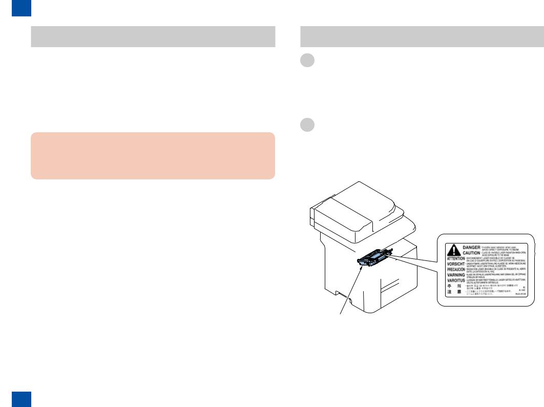
Handling Laser Scanner Unit
Before providing service works for the laser scanner unit and its peripherals, ensure to turn off the power of the device.
Any cover with potential dangers of laser beam reflection has affixed the caution label at the position shown in the figure below.
[1]
F-0-3
0-2
0 Safety Precautions > Laser Safety > Handling Laser Scanner Unit

0 Safety Precautions > Notes On Assembly/Disassembly
Toner Safety
About Toner
 CAUTION:
Never throw toner in flames to avoid explosion.
Handling Adhered Toner
•Use dry tissue paper to wipe off toner adhered to skin or clothes and wash in water.
•Never use warm water for cleaning up toner to prevent toner particles from being gelated to soak into fibers permanently.
•Toner particles are reactive with vinyl polymers. Avoid contacting these materials.
 CAUTION:
Risk Of Explosion If Battery Is Replaced By An Incorrect Type.
 CAUTION:
Wenn mit dem falschen Typ ausgewechselt, besteht Explosionsgefahr.
Gebrauchte Batterien gemäß der Anleitung beseitigen.
0-3
Notes On Assembly/Disassembly
Follow the items below to assemble/disassemble the device.
1.Disconnect the power plug to avoid any potential dangers during assembling/disassembling works.
2.If not specially instructed, reverse the order of disassembly to reinstall.
3.Ensure to use the right screw type (length, diameter, etc.) at the right position when assembling.
4.To keep electric conduction, binding screws with washers are used to attach the grounding wire and the varistor. Ensure to use the right screw type when assembling.
5.Unless it is specially needed, do not operate the device with some parts removed.
6.Never remove the paint-locked screws when disassembling.
CAUTION
DOUBLE POLE/NEUTRAL FUSING
F-0-4
0-3
0 Safety Precautions > Notes On Assembly/Disassembly

1 |
Product Overview |
■Product Lineups |
■Product Features
■Specifications
■Name of Parts
1 Product Overview
1 Product Overview > Product Lineups > Main Unit
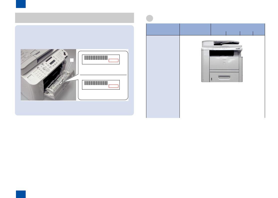
MEMO:
This product has two model types according to the country: TYPE I and TYPE II.
The way of distinguishing TYPE I and TYPE II is written in the Label [1] inside the
Cartridge Cover.
[1] |
|
120-127V |
Serial No. ETNXXXXX |
TYPE II |
|
|
|
TYPE II
120-127V
Serial No. ETNXXXXX
TYPE I
F-1-1
Be sure to check the type, and then refer to the Service Manual.
|
|
|
1-2 |
|
|
|
|
Function |
Canon i-SENSYS |
Canon imageCLASS Series |
|
|
Series |
|
|
|
MF6680dn |
D1120 |
D1150 D1170 D1180 |
Appearance
|
|
|
|
F-1-2 |
|
|
|
|
|
|
|
|
|
Copy |
O |
O |
O |
|
O |
O |
O |
O |
O |
|
O |
O |
|
Fax |
O |
- |
O |
|
O |
O |
USB Scan |
- |
- |
- |
|
- |
- |
Network Scan |
O |
O |
O |
|
O |
O |
Remote UI |
O |
O |
O |
|
O |
O |
DADF |
O |
O |
O |
|
O |
O |
Automatic 2-sided Print |
O |
O |
O |
|
O |
O |
T-1-1
1-2
1 Product Overview > Product Lineups > Main Unit
1 Product Overview > Product Features > Features > Power-saving MFP
Options
[2]
|
|
|
[1] |
|
|
|
F-1-3 |
No. |
Name |
Description |
Remarks |
[1] Canon Cassette Feeding Unit-U1 |
Approx. 500 Sheets (Plain paper |
- |
|
|
|
80g/ m2) |
|
[2] TELEPHONE 6 KIT Long cord Cool White |
|
MF6680dn |
|
T-1-2
1-3
Product Features
Features
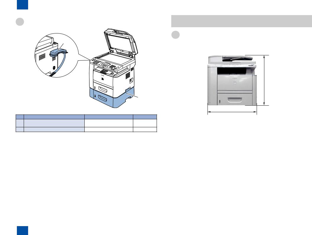
■ Compact MFP
The product compactified with lower height.
464mm
450mm
F-1-4
■ High-speed MFP
This compact A4 color MFP can prints at high speeds of up to 30 pages per minute (A4/LTR).
■ Power-saving MFP
This product employed SURF fixing method with a ceramic heater and 3W sleep mode to achieve electric power saving.
1-3
1 Product Overview > Product Features > Features > Power-saving MFP

1 Product Overview > Specifications > Main Unit Specifications
Specifications
Item |
Specification/function |
|
Body |
Desktop (DADF standard type) |
|
Light Source Type |
LED |
|
Photosensitive Medium |
OPC drum |
|
Image Reading Method |
Contact Sensor Reading Method |
|
Reproduction Method |
Indirect electrostatic copying method |
|
Exposure Method |
Semiconductor laser |
|
Charging Method |
Roller contact charging method |
|
|
|
|
Development Method |
Dry system - element jumping development method |
|
Transfer Method |
Roller transfer method |
|
Separation Method |
Electrostatic separation (neutralizing needle) and curvature |
|
separation |
||
|
||
Pickup Method |
Cassette pick-up: 1 cassette |
|
Multi manual feeding pick-up |
||
|
||
Cassette Pickup Method |
Pad separation method |
|
Multifeeder Pickup Method |
Pad separation method |
|
Drum Cleaning Method |
Rubber blade |
|
Fixing Method |
On-demand |
|
Toner Type |
Magnetic negative toner |
|
Toner Supply Type |
By drum style toner cartridge |
|
Toner Save Mode |
Yes |
|
Original Type |
Sheets, books, solids (up to 2 kg) |
|
Maximum Original Size |
Fixed: 216mm x 356mm |
|
ADF: 216mm x 356mm |
||
|
||
Reproduction Ratio |
Zoom: 0.50 to 2.00 (specified by the percent) |
|
|
16.0 seconds or less* |
|
|
(temperature: 20 deg C, humidity: 65%; from when the machine |
|
Warm-up Time |
turns ON the main power switch until the standby display appears) |
|
|
* Warm-up time may diff er depending on the condition and |
|
|
environment of the machine. |
|
Reading Resolution |
<TEXT/PHOTO>: 300 dpi x 600 dpi |
|
<TEXT>, <PHOTO>, <TEXT/PHOTO+>: 600 dpi x 600 dpi |
||
|
||
Printing Resolution |
600 x 600 dpi |
|
|
|
|
First Print Time |
6 seconds or less (A4/LTR) |
|
|
|
1-4
Item |
Specification/function |
|
First Copy Time |
8 seconds or less (A4/LTR) |
|
|
|
|
Print Speed |
Approximately 30 sheets / minute (A4/LTR) |
|
Cassette Paper Size |
LTR, LGL, A4, B5, A5, Executive, Oficio, Brazil-Oficio, Mexico- |
|
Oficio, FLSP, A-FLS, Government-LTR, Government-LGL |
||
|
||
Multifeeder Paper Size |
76 × 127 to 216 × 356 mm |
|
Cassette Paper Type |
Plain Paper (80g / m2), Plain Paper (60 to 80 g/m2) recycled paper |
|
(64 to 80 g/m2), Color (64 g/m2), Heavy Paper 1 (90 to 120 g/m2), |
||
|
Plain Paper (80g / m2), Plain Paper (60 to 80 g/m2), recycled paper Multifeeder Tray Paper Type (64 to 80 g/m2), Color (64 g/m2), Heavy Paper 1 (90 to 150 g/m2), Heavy Paper 2 (151 to 163 g/m2), Transparency, Labels, Envelopes
Cassette Capacity |
500 sheets (80g / m2) |
|
Multifeeder Tray Capacity |
50 sheets (80g / m2) |
|
Delivery Tray Stack |
65 sheets (60 - 80g / m2) |
|
|
|
|
Continuous Reproduction |
1 to 99 sheets |
|
Duplex Method |
Auto Duplexing |
|
Life of Cartridge |
Approx.5000 sheets (Starter Cartridge:Approx.2,300 sheets) |
|
Interface |
Standard:USB2.0, option:No |
|
Hard Disk |
Standard:No, option:No |
|
Memory |
128MB |
|
Energy Save Mode |
Yes. (Manual ON / OFF, automatically OFF after a set period of |
|
time, automatically ON when receiving facsimile / print data) |
||
|
||
Operating Environment |
10 to 30 degrees C |
|
(Temperature Range) |
||
|
||
Operating Environment |
20 to 80 % |
|
(Humidity Range) |
||
|
||
|
|
|
Operating Environment |
0.16 to 1.01 hPa (0. 6 to 1 bar) |
|
(Atmospheric Pressure) |
||
|
||
Power Supply Rating |
120V-127V (60Hz) |
|
220-240V, 50/60Hz |
||
|
||
Power Consumption |
Maximum consumption: Less than 1090 W |
|
(Maximum) |
||
|
||
|
During operation: approximately 550W or less (reference value) |
|
Power Consumption |
At standby: approximately 18W (referenve velue)In sleep mode: |
|
|
approximately 3W (reference value) |
|
Dimensions |
464 mm (H) × 472 mm (D) × 450 mm (W) |
|
Weight |
Approximately 20.6 kg (including the toner cartridge) |
|
Network |
Yes |
1-4
1 |
> Main Unit Specifications |
|

|
|
|
|
|
|
|
|
|
|
Item |
Specification/function |
|
PDL |
BDL-Image, PCL5 / PCLXL |
|
|
|
|
|
|
SEND |
Yes |
|
|
|
|
T-1-3 |
|
ADF Specifications |
||
Item |
Specification/function |
Original position |
center reference |
Original processing mode |
1-sided to 1-sided copy, 2-sided to 2-sided copy, 1-sided to 2-sided |
copy, 2-sided to 1-sided copy |
|
Original reading |
stream reading method |
|
|
Stack |
A4/LTR: 50 sheets, LGL: 30 sheets |
Mixed original sizes |
Yes |
Original AE detection |
No |
Original size recognition |
No |
|
|
Stamp |
No |
|
|
Operating environment |
pursuant to the host machine |
T-1-4
1-5
Item |
Specification/function |
Suitable Line |
Public Switched Telephone Network (PSTN) |
|
Up to 28.8Kbps in modem speed is currently available in PSTN. Note |
|
that available modem speed is telephone-line dependent. |
|
Telephone line connection: 1 |
Communication Protocol |
Super G3 |
Modulation Method |
Image modulation : V.34/V.8/V.17/V.29/V.27ter |
|
Transmission procedure : V.21 |
Transmission Speed |
33,600 bps |
Coding |
Compression method: JBIG, MMR, MR, MH |
Error Correction |
ECM |
Minimum Receivable Input |
V.17, V.27ter, V.29: -6 to -43 dBm |
Level |
V.34: -10 to -43 dBm |
Modem IC |
CONEXANT DFX336 |
Scanning Line Density |
Normal : 8 dots/mm x 3.85 lines/mm |
|
Fine : 8 dots/mm x 7.7 lines/mm |
|
Super fine : 8 dots/mm x 15.4 lines/mm |
|
Ultra fine : 16 dots/mm x 15.4 lines/mm |
Half Tone |
256 tones |
Reproduction Resolution |
600 x 600 dpi |
Receivable Reduction |
Automatic reduction: 75-100% (1% increment) |
Setting |
|
FAX/TEL Switching |
Available |
Answering Machine |
Available |
Transfer Setting |
|
Remote Reception |
Available |
Auto-dialing |
Available |
Delayed Transmission |
Available |
Broadcast Transmission |
Destinations: up to 201 |
Dual Access |
Up to 70 schedules |
Image Data Backup |
Available |
T-1-5
1-5
1 Product Overview > Specifications > FAX Specifications

1 Product Overview > Specifications > Paper types
Paper type |
Cassette |
MP Tray |
OP Cassette |
|||
|
1-sided |
2-sided |
1-sided |
2-sided |
1-sided |
2-sided |
A4 |
30 |
16.4 |
30 |
16.4 |
30 |
16.4 |
LTR |
30 |
16.7 |
30 |
16.7 |
30 |
16.7 |
LGL |
25.3 |
13.1 |
25.3 |
13.1 |
25.3 |
13.1 |
B5 |
13>12>8>6 |
- |
16>12>8>6 |
- |
10>10>8>6 |
- |
|
|
|
|
|
|
|
A5 |
15>12>8>6 |
- |
17>12>8>6 |
- |
11>11>8>6 |
- |
Strip of paper (90 to |
- |
- |
2>1 |
- |
- |
- |
297 mm) |
|
|
|
|
|
|
Postcard |
- |
- |
17>12>8>6 |
- |
- |
- |
Envelope |
- |
- |
17>12>8>6 |
- |
- |
- |
|
|
|
|
|
|
T-1-6 |
1-6
|
Paper types |
Printer driver setting |
Cassette |
Multi-purpose |
|
|
|
|
|
|
Tray |
Plain |
|
From 16 to 21 lb |
Plain Paper |
|
|
|
|
(60 to 80 g/m2) |
|
|
|
|
|
From 16 to 21 lb |
Plain Paper L |
|
|
|
|
(60 to 80 g/m2) |
|
|
|
Color |
|
17 lb (64 g/m2) |
Color |
|
|
Recycled* |
|
From 17 to 21 lb |
Recycled |
|
|
|
|
(64 to 80 g/m2) |
|
|
|
Thick |
|
From 24 to 32 lb |
Heavy Paper 1 |
|
- |
|
|
(90 to 120 g/m2) |
|
|
|
|
|
From 24 to 40 lb |
|
- |
|
|
|
(90 to 150 g/m2) |
|
|
|
|
|
From 40 to 43 lb |
Heavy Paper 2 |
- |
|
|
|
(151 to 163 g/m2) |
|
|
|
Transparency |
|
Transparency *1 |
- |
|
|
Label |
|
|
Label |
- |
|
Envelope |
|
|
Envelope |
- |
|
T-1-7
*1: Use only LTR or A4 transparencies made especially for this machine.
1-6
1 Product Overview > Specifications > Paper types
1 Product Overview > Name of Parts > External View > Front Side
Paper size |
Cassette |
Multi-purpose Tray |
A4 (210.0 mm × 297.0 mm) |
|
|
B5 (182.0 mm × 257.0 mm) |
|
|
A5 (148.0 mm × 210.0 mm) |
|
|
Legal (LGL) (215.9 mm × 355.6 mm) |
|
|
Letter (LTR) (215.9 mm × 279.4 mm) |
|
|
Executive (EXEC) (184.0 mm × 266.7 mm) |
|
|
Officio (215.9 mm × 317.5 mm) |
|
|
Brazil Officio (215.9 mm × 355.6 mm) |
|
|
Mexico Officio (215.9 mm × 341 mm) |
|
|
Government Letter (203.2 mm × 266.7 mm) |
|
|
Government Legal (203.2 mm × 330.2 mm) |
|
|
FOOLSCAP (215.9 mm × 330.2 mm) |
|
|
A-FLS (205.7 mm × 337.82mm) |
|
|
3"×5" to Legal (76 × 127 to 216 mm× 356 mm) |
- |
|
T-1-8
1-7
Name of Parts
External View
■ Front Side
[1] |
[2] |
[3] |
|
[11] |
|
[4] |
|
|
|
|
|
[10] |
|
[5] |
[12] |
|
|
[13] |
|
[9] |
|
|
|
|
|
|
[14]
[8] |
[7] |
[6] |
[16] |
[15] |
F-1-5
1-7
1 Product Overview > Name of Parts > External View > Front Side
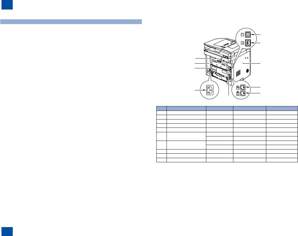
1 Product Overview > Name of Parts > External View > Rear Side
Key |
Name |
Service Pars No. |
Remarks |
Reference |
[1] |
DADF (Duplex Automatic |
- |
- |
(Refer to page 4-30) |
|
Document Feeder) |
|
|
|
[2] |
Slide Guides |
FC9-1501 |
Front |
- |
|
|
FC9-1502 |
Rear |
|
[3] |
Document Feeder Tray |
FM3-9534 |
- |
- |
[4] |
Document Delivery Tray |
- |
- |
- |
[5] |
Control Panel |
FM3-9803 |
(D1180 TYPE I) |
(Refer to page 4-70) |
|
|
FM4-6439 |
(D1180 TYPE II) |
|
|
|
FM3-9817 |
(D1170 TYPE I) |
|
|
|
FM4-6440 |
(D1170 TYPE II) |
|
|
|
FM3-9818 |
(D1150 US,CA,LTN |
|
|
|
|
TYPE I) |
|
|
|
FM4-6441 |
(D1150 US,CA,LTN |
|
|
|
|
TYPE II) |
|
|
|
FM4-1649 |
(D1150 LTN,SG,AU |
|
|
|
|
TYPE I) |
|
|
|
FM4-6443 |
(D1150 LTN,SG,AU |
|
|
|
|
TYPE II) |
|
|
|
FM4-1651 |
(D1150 KR TYPE I) |
|
|
|
FM4-6445 |
(D1150 KR TYPE II) |
|
|
|
FM4-6444 |
(D1150 CN TYPE II) |
|
|
|
FM3-9819 |
(D1120 TYPE I) |
|
|
|
FM4-6442 |
(D1120 TYPE II) |
|
|
|
FM4-1647 |
(MF6680dn TYPE I) |
|
|
|
FM4-6446 |
(MF6680dn TYPE II) |
|
|
|
FM4-1648 |
(MF6640dn TYPE I) |
|
[6] |
Right Cover |
FC9-2055 |
- |
(Refer to page 4-23) |
[7] |
Multi-purpose Tray |
- |
- |
- |
[8] |
Multi-purpose Tray Extension |
- |
- |
- |
[9] |
Slide Guides for Multi-purpose |
- |
- |
- |
|
Tray |
|
|
|
[10] |
Paper Stopper |
- |
- |
- |
[11] |
Upper Cover |
FC9-1999 |
- |
(Refer to page 4-28) |
[12] |
Reader Unit |
FM3-9525 |
- |
(Refer to page 4-35) |
[13] |
Open Button |
- |
- |
- |
[14] |
Front Cover |
- |
- |
(Refer to page 4-26) |
[15] |
Main Power Switch |
FM4-1656 |
(TYPE I) |
- |
|
|
FM4-5367 |
(TYPE II) |
|
[16] |
Paper Cassette |
FM3-9798 |
- |
- |
|
|
|
|
T-1-9 |
1-8
■ Rear Side
|
|
|
[1] |
|
|
|
|
[2] |
|
|
[10] |
|
|
|
|
[9] |
|
[3] |
|
|
[8] |
|
|
|
|
[7] |
|
[4] |
|
|
|
[5] |
|
|
|
|
|
|
|
|
|
[6] |
|
|
|
|
|
F-1-6 |
|
Key |
Name |
Service Pars No. |
Remarks |
Reference |
[1] |
USB Port |
- |
- |
- |
[2] |
Ethernet Port |
- |
- |
- |
[3] |
Left Cover |
FC9-2017 |
- |
(Refer to page 4-19) |
[4] |
External Device Jack |
- |
- |
- |
[5] |
Telephone Line Jack |
- |
- |
- |
[6] |
Left Rear Cover |
FC9-2020 |
(FAX Model) |
(Refer to page 4-22) |
|
|
FC9-4916 |
(Except FAX Model) |
- |
[7] |
Power Socket |
FM4-1607 |
(TYPE I) |
- |
|
|
FM4-5386 |
(TYPE II) |
- |
[8] |
Duplex Unit Cover |
- |
- |
- |
[9] |
Right Rear Cover |
FC9-2056 |
- |
(Refer to page 4-26) |
[10] |
Rear Cover |
FM3-9791 |
- |
- |
T-1-10
1-8
1 Product Overview > Name of Parts > External View > Rear Side

1 Product Overview > Name of Parts > Cross Sectional View > Printer
Cross Sectional View
■ADF/Reader Unit
[1][2] [3]
|
|
|
|
|
|
|
F-1-7 |
|
|
|
|
|
|
|
|
|
|
|
|
|
|
||
Key |
Name |
|
|
Service Pars No. |
Reference |
||
[1] |
ADF Paper Feed Roller |
|
|
FM3-9540 |
- |
||
[2] |
ADF Separation Roller |
|
|
FL2-6637 |
(Refer to page 4-39) |
||
[3] |
ADF Pickup Roller |
|
|
FC7-6189 |
(Refer to page 4-38) |
||
[4] |
ADF Delivery roller |
|
|
FM4-1875 |
- |
||
[5] |
ADF Separation Pad |
|
|
FC7-6297 |
(Refer to page 4-41) |
||
T-1-11
1-9
■ Printer
[7]
|
[3] |
[4] |
[6] |
[8] |
[9] |
[2] |
|
|
|
|
[10] |
|
|
|
|
|
|
[1] |
|
|
|
|
|
|
[18] |
|
|
|
[11] |
|
|
|
|
|
|
[5] |
[17] |
|
|
|
[12] |
|
|
|
|
[13]


 [14]
[14]
[20]
[15]
|
[19] |
[16] |
|
|
|
|
F-1-8 |
|
|
|
|
Key |
Name |
Service Pars No. |
Reference |
[1] |
Fixing delivery roller |
- |
- |
[2] |
Face-down delivery roller |
FM4-1875 |
- |
[3] |
Fixing unit |
RM1-6405 (120V) |
(Refer to page 4-98) |
|
|
RM1-6406 (230V) |
|
[4] |
Fixing film unit |
- |
- |
[5] |
Pressure roller |
- |
- |
[6] |
Laser scanner unit |
RM1-6424 |
(Refer to page 4-93) |
[7] |
Copyboard glass (scanning glass) |
- |
(Refer to page 4-46) |
[8] |
Cartridge |
- |
- |
[9] |
Registration shutter |
- |
- |
[10] |
Registration roller |
RM1-6419 |
- |
1-9
1 Product Overview > Name of Parts > Cross Sectional View > Printer

|
|
|
|
|
|
|
|
|
|
|
Key |
Name |
Service Pars No. |
Reference |
|
[11] |
Multi-purpose tray pickup roller |
RL1-2120 |
(Refer to page |
|
|
|
|
4-108) |
|
[12] |
Multi-purpose tray separation pad |
RL1-2115 |
(Refer to page |
|
|
|
|
4-108) |
|
[13] |
Feed roller |
- |
- |
|
[14] |
Cassette pickup roller |
RM1-6414 |
(Refer to page |
|
|
|
|
4-106) |
|
[15] |
Cassette separation pad |
RM1-6454 |
(Refer to page |
|
|
|
|
4-107) |
|
[16] |
Duplex re-pickup roller |
- |
- |
|
[17] |
Transfer roller |
RM1-6450 |
(Refer to page 4-95) |
|
[18] |
Photosensitive drum |
- |
- |
|
[19] |
Duplex feed roller |
- |
- |
|
[20] |
Duplex feed unit |
RM1-6441 |
(Refer to page |
|
|
|
|
4-104) |
|
|
|
|
T-1-12 |
1-10
Key |
Name |
Key |
Name |
[7] |
[COPY] key |
[22] |
[Image Quality] key |
|
|
|
|
[8] |
[SEND/FAX] key (For the D1180/D1170/MF6680dn) |
[23] |
[+] key |
|
[FAX] key (For the D1150) |
|
|
|
[SEND] key (For the MF6640dn)" |
|
|
[9] |
[SCAN] key |
[24] |
[OK] key |
[10] |
[Paper Settings] key |
[25] |
[-] key |
[11] |
Numeric keys |
[26] |
[Job Cancel/Status Monitor] key |
[12] |
[Log In/Out] key (ID key) |
[27] |
[View Settings] key |
|
|
|
|
[13] |
[Clear] key |
[28] |
[2-Sided] key |
[14] |
[Report] key |
[29] |
2-Sided mode indicator |
[15] |
[Energy Saver] key |
|
|
|
|
|
T-1-13 |
■ Send Operation Panel
Operation Panel
■ Main Operation Panel |
|
|
|
|
|
|
|
|
|
|
|
|
|
|
|
|
|
Panel |
|
open |
||||||||||||||||||||||
|
|
|
|
|
|
|
|
|
|
|
|
|
|
|
|
|
|
|||||||||||||||||||||||||
[1] [2] [3] [4] [5] [6] [7] [8] [9] |
[10] [11] |
[12] [13] [14] [15] |
|
|
||||||||||||||||||||||||||||||||||||||
|
|
|
|
|
|
|
|
|
|
|
|
|
|
|
|
|
|
|
|
|
|
|
|
|
|
|
|
|
|
|
|
|
|
|
|
|
|
|
|
|
|
|
|
|
|
|
|
|
|
|
|
|
|
|
|
|
|
|
|
|
|
|
|
|
|
|
|
|
|
|
|
|
|
|
|
|
|
|
|
|
|
|
|
|
|
|
|
|
|
|
|
|
|
|
|
|
|
|
|
|
|
|
|
|
|
|
|
|
|
|
|
|
|
|
|
|
|
|
|
|
|
|
|
|
|
|
|
|
|
|
|
|
|
|
|
|
|
|
|
|
|
|
|
|
|
|
|
|
|
|
|
|
|
|
|
|
|
|
|
|
|
|
|
|
|
|
|
|
|
|
|
|
|
|
|
|
|
|
|
|
|
|
|
|
|
|
|
|
|
|
|
|
|
|
|
|
|
|
|
|
|
|
|
|
|
|
|
|
|
|
|
|
|
|
|
|
|
|
|
|
|
|
|
|
|
|
|
|
|
|
|
|
|
|
|
|
|
|
|
|
|
|
|
|
|
|
|
|
|
|
|
|
|
|
|
|
|
|
|
|
|
|
|
|
|
|
|
|
|
|
|
|
|
|
|
|
|
|
|
|
|
|
|
|
|
|
|
|
|
|
|
|
|
|
|
|
|
|
|
|
|
|
|
|
|
|
|
|
|
|
|
|
|
|
|
|
|
|
|
|
|
|
|
|
|
|
|
|
|
|
|
|
|
|
|
|
|
|
|
|
|
|
|
|
|
|
|
|
|
|
|
|
|
|
|
|
|
|
|
|
|
|
|
|
|
|
|
|
|
|
|
|
|
|
|
|
|
|
|
|
|
|
|
|
|
|
[1] |
[2] |
[5] |
[5] |
[4] |
[3] |
F-1-10
|
|
|
|
|
|
|
|
|
|
|
|
|
|
|
|
|
|
|
|
|
|
|
|
|
|
|
|
|
|
|
|
|
|
Key |
Name |
Key |
Name |
[29] |
[28] |
[27] |
[26] |
[25] |
[24] |
[23] |
[22] |
[21] |
[20] |
[19] |
|
|
|
|
|
|
|
|
|||||||||||||||||||
[18] |
|
[17] |
|
[16] |
|
||||||||||||||||||||||||||||||||
|
|
|
|
|
|
|
|
|
|
|
|
|
|
|
|
|
|
|
|
|
|
|
|
|
|
|
|
|
|
|
|
|
|
|
|
|
|
|
|
|
|
|
|
|
|
|
|
|
|
|
|
|
|
|
|
|
|
|
|
|
|
|
|
|
|
|
|
|
|
F-1-9 |
|
[1] |
[Address Book] key |
[4] |
[Hook] key |
|
|
|
|
|
|
|
|
|
|
|
|
|
|
|
|
|
|
|
|
|
|
|
|
|
|
|
|
|
|
|
|
|
|||||
|
|
|
|
|
|
|
|
|
|
|
|
|
|
|
|
|
|
|
|
|
|
|
|
|
|
|
|
|
|
|
|
|
|
[2] |
[Recall/Pause] key (For the D1180/D1170/MF6680dn) |
[5] |
[Coded Dial] key |
Key |
|
|
|
|
|
|
|
Name |
|
|
|
|
|
|
|
|
|
Key |
|
|
|
Name |
|
||||||||||||||
|
|
|
|
|
|
|
|
|
|
|
|
|
|
|
|
|
|
|
|
|
|
[Redial/Pause] key (For the D1150)" |
|
|
|||||||||||||
[1] |
|
Paper Select indicator |
|
|
|
|
|
|
|
|
|
[16] |
[Stop/Reset] key |
|
|
|
|
|
|||||||||||||||||||
|
|
|
|
|
|
|
|
|
|
||||||||||||||||||||||||||||
|
|
|
|
|
|
|
|
|
|
|
|
[3] |
[Coded Dial] key |
|
|
||||||||||||||||||||||
|
[2] |
[Collate/2 on 1] key |
|
|
|
|
|
|
|
|
|
[17] |
[Start] key |
|
|
|
|
|
|
|
|
|
|
||||||||||||||
|
|
|
|
|
|
|
|
|
|
|
|
|
|
|
|
|
|
|
|
|
T-1-14 |
||||||||||||||||
[3] |
|
[Paper Select] key |
|
|
|
|
|
|
|
|
|
[18] |
Error indicator |
|
|
|
|
|
|
||||||||||||||||||
|
|
|
|
|
|
|
|
|
|
|
|
|
|
||||||||||||||||||||||||
[4] |
|
[Enlarge/Reduce] key |
|
|
|
|
|
|
|
|
|
[19] |
Processing/Data indicator |
|
|
|
|
|
|
||||||||||||||||||
|
|
|
|
|
|
|
|
|
|
|
|
|
|
|
|
|
|
|
|
||||||||||||||||||
[5] |
|
[Menu] key |
|
|
|
|
|
|
|
|
|
[20] |
[Tone] key |
|
|
|
|
|
|
|
|
|
|
|
|
||||||||||||
[6] |
|
Display |
|
|
|
|
|
|
|
|
|
[21] |
[Density] key |
|
|
|
|
|
|
|
|
|
|
|
|
||||||||||||
1-10
1 Product Overview > Name of Parts > Operation Panel > Send Operation Panel
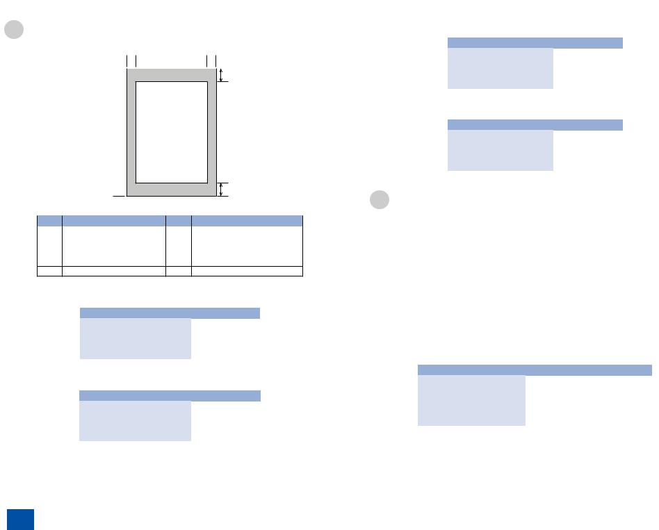
1 |
Product Overview > Name of Parts > Operation Environment of the Printer Driver > Network Specifications |
|
Function List |
1-11 |
|
■ BDL Print |
||
[2] |
[4] |
[3]
[1]


[7][5]
|
|
|
F-1-11 |
|
|
|
|
Key |
Item |
Key |
Item |
[1] leading edge of original |
[6] |
trailing edge margin |
|
[2] |
left margin |
[7] |
non-scanning area |
[3] |
effective scanning width |
[8] |
scanning range |
[4] |
right margin |
[9] trailing edge of original |
|
[5]leading edge margin
Item |
Size |
left margin |
5.0 mm |
right margin |
5.0 mm |
leading edge margin |
5.0 mm |
trailing edge margin |
5.0 mm |
■ PCL Print Area
Item |
Size |
left margin |
4.2 mm |
right margin |
4.2 mm |
leading edge margin |
4.2 mm |
trailing edge margin |
4.2 mm |
Operation Environment of the Printer Driver
■ Operation environment
Microsoft Windows 98/98SE/Me, Windows 2000 Server, Windows 2000 Professional, Windows XP Professional, Windows XP Home Edition, Windows Server 2003, Windows Vista, Windows 7, MacOS X v10.2.8 or later
■ Copy Area
Item |
Size |
left margin |
5.0 mm |
right margin |
5.0 mm |
leading edge margin |
5.0 mm |
trailing edge margin |
5.0 mm |
■ Reception Print Area
Item |
Size |
left margin |
4.0 mm |
right margin |
4.0 mm |
leading edge margin |
5.0 mm |
trailing edge margin |
5.0 mm |
■ Hardware environment
-IBM PC or IBM compatible PC
-CD-ROM drive or network environment accessible to CD-ROM
-PC equipped with USB port and installed with USB class driver
■ Network Specifications
Name |
Item |
Connector |
RJ45 |
Interface |
Ethernet II |
Communication Speed |
10Base-T/100Base-TX |
Communication Mode |
FULL DUPLEX/half DUPLEX |
Supported Protocol |
TCP/IP |
1-11
1 Product Overview > Name of Parts > Operation Environment of the Printer Driver > Network Specifications

1 Product Overview > Name of Parts > Operation Environment of the Printer Driver > SEND Specifications
1-12
■ SEND Specifications
The Send function is available for the MF6680dn/D1170/D1180.
Send to file server
Communication Protocol |
SMB (TCP/IP) |
Data Format |
TIFF (B&W), PDF (B&W), JPEG (Color), PDF (Compact) (Color) |
Resolution |
100 x 100 dpi, 150 x 150 dpi, 200 x 100 dpi, 200 x 200 dpi, 300 x 300 |
|
dpi, 400 x 400 dpi, 600 x 600 dpi |
System Environment |
Windows 2000 Server/Professional (SP1 or later), Windows XP |
|
Professional/Home Edition, Windows Vista, Windows 7, Windows |
|
Server 2003, Windows Server 2008, Mac OS X, Red Hat Linux 7.2 |
Interface |
100BASE-TX, 10BASE-T |
Color Mode |
Color, B&W (black and white) |
Original Type |
Text, Text/Photo, Photo |
|
T-1-15 |
|
|
|
|
Communication Protocol |
SMTP, POP3 |
Resolution |
100 x 100 dpi, 150 x 150 dpi, 200 x 100 dpi, 200 x 200 dpi, 300 x 300 |
|
dpi, 400 x 400 dpi, 600 x 600 dpi |
Format |
TIFF (B&W), PDF (B&W), JPEG (Color), PDF (Compact) (Color) |
Original Size |
LTR, LGL, STMTR, STMT, A4, A5, B5 |
Server Software |
Microsoft Exchange Server 5.5 (SP2), Sendmail 8.11.2, Lotus Domino |
|
R4.5/R5 |
|
T-1-16 |
|
|
Facsimile |
|
Applicable Line |
Public Switched Telephone Network (PSTN)*1 |
Compatibility |
G3 |
Data Compression Schemes |
MH, MR, MMR, JBIG |
Modem Speed |
33.6 Kbps |
|
Automatic fallback |
Transmission Speed |
Approx. 3 seconds/page*2 at 33.6 Kbps, ECM-MMR, |
|
transmitting from the memory |
Transmission/Reception |
Maximum approx. 512 pages*2 |
Memory |
(total pages of transmission/reception) |
Fax Resolution |
FINE: 203 pels/inch x 196 lines/inch (8 pels/mm x 7.7 lines/mm) |
|
PHOTO: 203 pels/inch x 196 lines/inch (8 pels/mm x 7.7 lines/mm) |
|
SUPER FINE: 203 pels/inch x 392 lines/inch (8 pels/mm x 15.4 lines/ |
|
mm) |
|
ULTRA FINE: 406 pels/inch x 392 lines/inch (16 pels/mm x 15.4 lines/ |
|
mm) |
|
STANDARD: 203 pels/inch x 98 lines/inch (8 pels/mm x 3.85 lines/ |
|
mm) |
|
T-1-17 |
1-12
1 Product Overview > Name of Parts > Operation Environment of the Printer Driver > SEND Specifications

2 TechnicalOverview
■Basic Configuration
■Document Exposure/
feeder System
■Engine Control System
■Laser Scanner System
■Image-formation System
■Fixing Unit System
■Media Feed System
2 Technical Overview
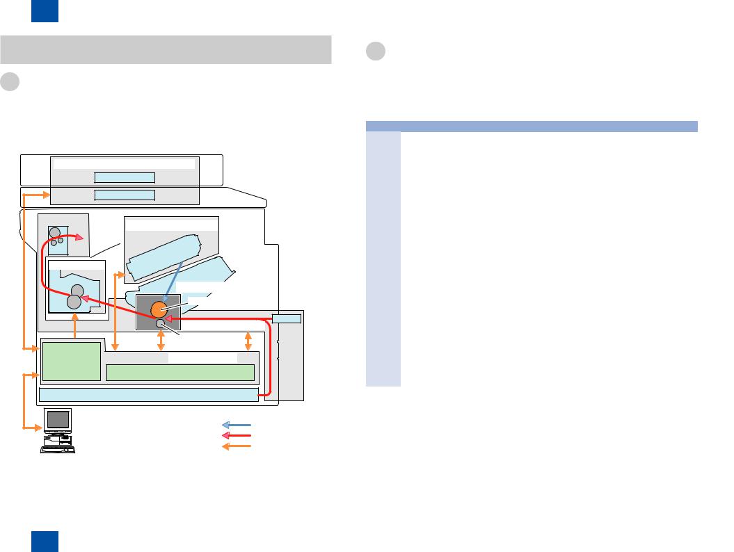
2 Technical Overview > Basic Configuration > Basic Sequence > Basic Operational Sequence
2-2
Basic Configuration
Configuration Function
This device is roughly composed of the 6 functional blocks as shown in the figure below
• |
Document Exposure/Delivery System |
• |
Image Formation System |
• |
Controller System |
• |
Fixing System |
• |
Laser Exposure System |
• |
Pickup / Feed System |
Document exposure/delivery system
ADF unit
Contact Sensor
Delivery unit
Laser Exposure System
Laser scanner
Fixing System |
Cartridge |
|
Fixing unit |
|
|
Image Formation System |
|
|
|
|
|
|
Photosensitive drum |
|
|
Pickup / Feed System |
MP Tray |
|
|
|
|
Transfer roller |
|
Main |
Controller system |
|
Controller |
Engine controller |
|
|
|
|
|
Casette |
|
|
Laser beam |
|
PC |
Paper flow |
|
|
Signal flow |
|
F-2-1
Basic Sequence
■ Basic Operational Sequence
|
Status |
Operation |
WAIT |
Interval from power-ON |
Activate the printer to be ready for printing. During WAIT |
(Wait) |
or reactivation from sleep |
time, the following operations are done: pressure is applied |
|
mode upon shutting the |
to the pressure roller of the Fixing Unit; check cartridges |
|
door(s) to entering the print- |
and units being in place; move the developing unit to the |
|
ready status |
home position; and, clean the ITB. When needed, color |
|
|
displacement is corrected and the image is stabilized. |
STBY |
Interval from the wait |
Maintain the print-ready status. The printer enters the sleep |
(STBY) |
time or the last rotation to |
mode upon receiving a “sleep” command from the main |
|
issuance of a print command |
controller during the stand-by status. The printer executes |
|
from the main controller or |
color displacement correction or image stabilization upon |
|
power-OFF. |
receiving corresponding commands from the main controller. |
INTR |
Interval from issuance of |
To make the printer ready for print jobs, activate high- |
(IINTR) |
a print command from the |
voltage bias PCBs, the Laser Scanner Unit and the Fixing |
|
main controller during the |
Unit. |
|
stand-by status to warming |
|
|
up the Fixing Unit to the |
|
|
target temperature. |
|
Interval from the initial |
Based on the video signals input from the main controller, |
|
(Print) |
rotation to completion of last |
form the static latent image on the photosensitive drum to |
|
page fixation. |
transfer and fix the toner image on paper. When a certain |
|
|
pages are printed after power-ON, the device undergoes |
|
|
color displacement correction and/or image stabilization. |
LSTR |
Interval from print job |
The last page of the print job is completely delivered. In |
(Last |
completion to Motor |
this status, the Laser Scanner Unit and high-voltage bias |
rotation) |
deactivation. |
PCBs are inactive. The printer starts the initial rotation upon |
|
|
receiving a print command from the main controller during |
|
|
this status. |
|
|
T-2-1 |
2-2
2 Technical Overview > Basic Configuration > Basic Sequence > Basic Operational Sequence
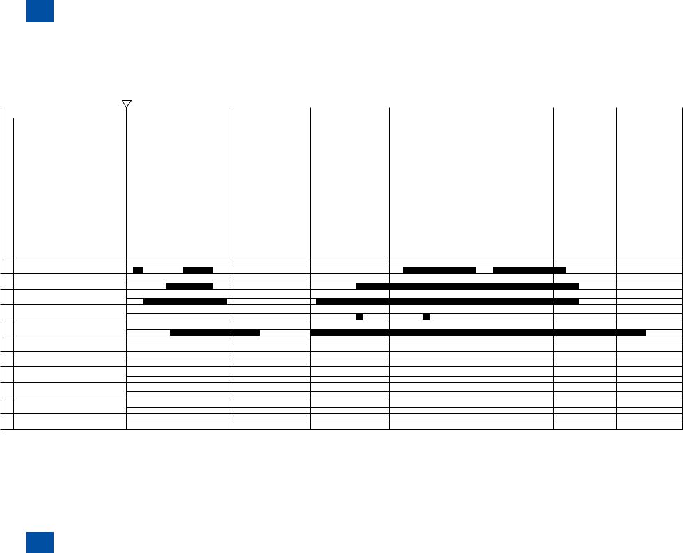
2 Technical Overview > Basic Configuration > Basic Sequence > Print Sequence
2-3
■ Print Sequence
Timing chart two consecutive prints on LTR paper
Power switch ON
|
Operation |
|
|
|
|
|
INTR |
|
|
|
|
|
|
|
LASTR |
STBY |
||||||||||||||
|
|
|
|
|
WAIT |
STBY |
|
|
|
|
|
|
|
|
|
|
||||||||||||||
1 |
TOP sensor (PS204) |
|
|
|
|
|
|
|
|
|
|
|
|
|
||||||||||||||||
|
|
|
|
|
|
|
|
|
|
|
|
|
|
|
|
|
|
|
|
|
|
|
|
|||||||
|
|
|
|
|
|
|
|
|
|
|
|
|
|
|
|
|
|
|
|
|
|
|
|
|
|
|
|
|
|
|
2 |
Fixing delivery sensor (PS915) |
|
|
|
|
|
|
|
|
|
|
|
|
|
|
|
|
|
|
|
|
|
|
|
|
|||||
|
|
|
|
|
|
|
|
|
|
|
|
|
|
|
|
|
|
|
|
|
|
|
|
|
|
|
|
|
|
|
3 |
Print start command (EEC12) |
|
|
|
|
|
|
|
|
|
|
|
|
|
|
|
|
|
|
|
|
|
|
|
|
|||||
|
|
|
|
|
|
|
|
|
|
|
|
|
|
|
|
|
|
|
|
|
|
|
|
|||||||
|
|
|
|
|
|
|
|
|
|
|
|
|
|
|
|
|
|
|
|
|
|
|
|
|
|
|
|
|
|
|
4 |
Scanner Motor (M202) |
|
|
|
|
|
|
|
|
|
|
|
|
|
|
|
|
|
|
|
|
|
|
|
|
|
|
|
|
|
|
|
|
|
|
|
|
|
|
|
|
|
|
|
|
|
|
|
|
|
|
|
|
|
|
|
|
|
|
|
|
5 |
Laser Diode |
|
|
|
|
|
|
|
|
|
|
|
|
|
|
|
|
|
|
|
|
|
|
|
|
|
|
|
||
|
|
|
|
|
|
|
|
|
|
|
|
|
|
|
|
|
|
|
|
|
|
|
|
|
|
|
|
|
|
|
6 |
BD Output signal (BDO) |
|
|
|
|
|
|
|
|
|
|
|
|
|
|
|
|
|
|
|
|
|
|
|
|
|||||
|
|
|
|
|
|
|
|
|
|
|
|
|
|
|
|
|
|
|
|
|
|
|
|
|
|
|
|
|
|
|
7 |
Main Motor (M201) |
|
|
|
|
|
|
|
|
|
|
|
|
|
|
|
|
|
|
|
|
|
|
|
|
|
|
|
|
|
8 |
Primary Charging Bias (AC) |
|
|
|
|
|
|
|
|
|
|
|
|
|
|
|
|
|
|
|
|
|
|
|
|
|
|
|||
|
|
|
|
|
|
|
|
|
|
|
|
|
|
|
|
|
|
|
|
|
|
|
|
|
|
|
|
|
|
|
9 |
Primary Charging Bias (DC) |
|
|
|
|
|
|
|
|
|
|
|
|
|
|
|
|
|
|
|
|
|
|
|
|
|
|
|||
|
|
|
|
|
|
|
|
|
|
|
|
|
|
|
|
|
|
|
|
|
|
|
|
|
|
|||||
|
|
|
|
|
|
|
|
|
|
|
|
|
|
|
|
|
|
|
|
|
|
|
|
|
|
|
|
|
|
|
10Developing Bias
11Transfer Charging Bias
12Fixing Heater (H201/H2010)
13 Cassette pickup solenoid (SL201)
14 Main Fan (FM201)
15
16
17
18
19
20
2-3
2 Technical Overview > Basic Configuration > Basic Sequence > Print Sequence

|
2 |
Technical Overview > Basic Configuration > Print Mode |
|||||
|
|
|
|
|
2-4 |
||
|
|
|
|
|
|
|
|
Print modes |
|
Feeding speed |
Media type |
Print speed |
Remarks |
|
|
Normal speed |
|
1/1speed |
Speed for plain paper A4 width (60 |
30 ppm |
|
|
|
mode |
|
|
to 90g) |
|
|
|
|
|
|
|
|
Transparencies |
|
|
|
1/2 speed mode |
|
1/2 speed |
Plain paper A4 width |
15 ppm |
|
|
|
|
|
|
|
(60 to 90g) |
|
|
|
|
|
|
|
Plain paper less than A4 width (60 |
|
|
|
|
|
|
|
to 90g) |
|
|
|
|
|
|
|
Heavy paper (90 to 150g) |
|
|
|
|
|
|
|
Heavy paper (151 to 163g) |
|
|
|
|
|
|
|
Bond paper (60 to 104g) |
|
|
|
|
|
|
|
Bond paper (105 to 163g) |
|
|
|
|
|
|
|
Label paper |
|
|
|
|
|
|
|
Postcard, Tab paper |
|
|
|
|
|
|
|
Envelope |
|
|
|
|
|
|
|
|
|
T-2-2 |
|
*1: Normal mode is recommended for Neenah Bond 60g/m2
2-4
2 Technical Overview > Basic Configuration > Print Mode
Loading...