

Page 1

PREFACE
Follow the instructions in this booklet when installing the Cassette Feeding Module-F1 or the Cassette Feeding
Module-H1 to its host machine.
The Cassette Feeding Module-F1 and the Cassette Feeding Module-H1 may be installed in the same way; the
steps herein are based on the installation of the Cassette Feeding Module-H1. (As long as there is no need for
distinction, both units are referred to as the cassette feeding module.)
– 2 –
Page 2
CASSETTE FEEDING MODULE-F1/
CASSETTE FEEDING MODULE-H1
INSTALLATION PROCEDURE
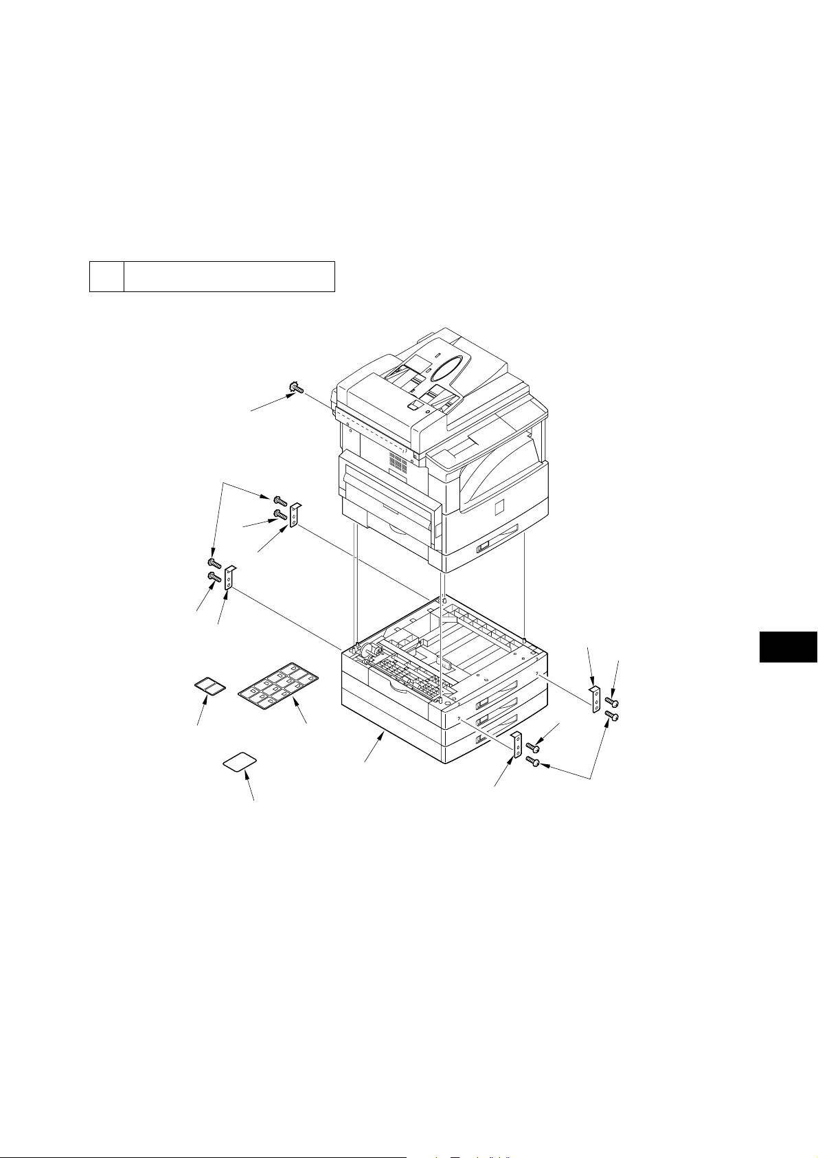
Unpack the shipping box, and check to make sure that none of the following is missing:
1 Checking the Contents
[7]
[6]
[6]
[2]
[6]
[2]
[3]
[5]
Attachments to the Cassette Feeding Module-F1
[1] Cassette feeding module ............................. 1 pc.
[2] Linking plate ...............................................4 pc.
[3] Paper size plate ........................................... 1 pc.
[4] Cassette size label .......................................1 pc.
[5] Warning sheet .............................................1 pc.
[6] B tightening screw ......................................8 pc.
[7] Toothed washer screw ................................1 pc.
[4]
[1]
[2]
[6]
[6]
[2]
Attachments to the Cassette Feeding Module-H1
[1] Cassette feeding module .............................1 pc.
[2] Link plate ....................................................4 pc.
[3] Paper size plate ...........................................3 pc.
[4] Cassette size label .......................................3 pc.
[5] Warning sheet .............................................3 pc.
[6] B tightening screw ......................................8 pc.
[7] Toothed washer screw ................................1 pc.
[6]
F1-1
– 3 –
Page 3
2 Installation
Be sure to observe the following when installing the
cassette feeding module to its host machine:
a. Be sure that the host machine has properly been
installed.
b. Be sure that the power plug of the host machine
is disconnected.
c. Be sure to identify the screws by type (length,
diameter) and location.
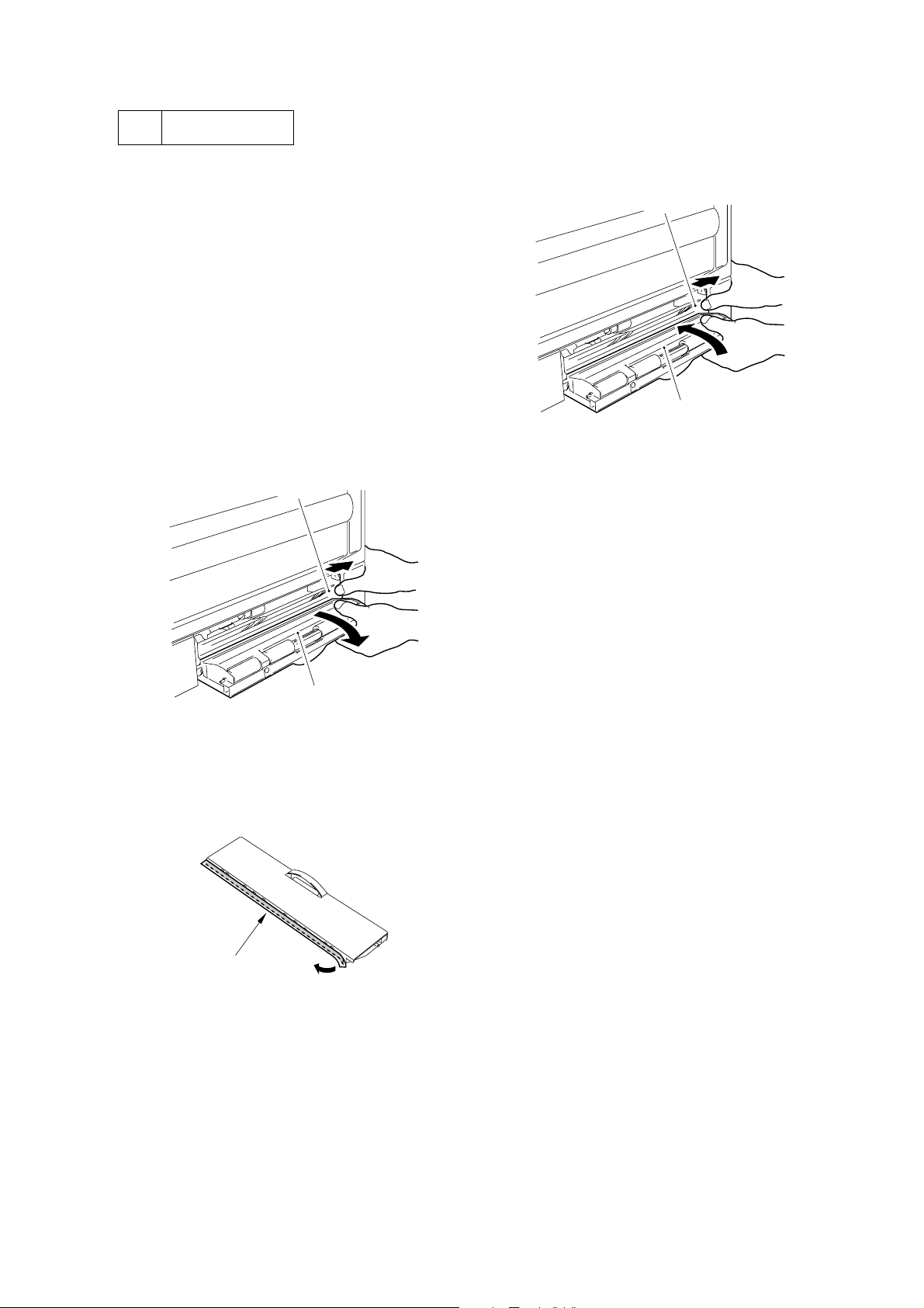
1. Preparing the Host Machine
1) Spread the support assembly [1] at the front/rear
of the left lower cover of the host machine with
a little force to detach the lower left cover [2].
[1]
3) Spread the support assembly [4] at the front/rear
of the left lower cover with a little force to
attach the left lower cover [5].
[4]
[5]
F2-3
[2]
F2-1
2) Peel off the left lower cover protective sheet [3].
[3]
F2-2
– 4 –
Page 4

2. Mounting the Cassette Feeding Module
1) Unpack the cassette feeding module, and place
it on a level surface.
2) Holding the host machine by supporting it as
shown, lift and place it on the cassette feeding
module. Be sure to match the front of the host
machine and that of the cassette feeding module
when doing so.
1. When lifting the host machine, be sure
to work as a group of two.
2. Be sure that both the cassette feeding
module and the host machine are
correctly oriented.
3. When placing the host machine, pay
extra attention to its side coming into
contact with the cassette feeding
module so that the gears will not be
damaged.
When lowering the host machine, be sure that the 2
pins [1] of the cassette feeding module are in the
host machine.
3) Move to the rear of the host machine, and
remove the 4 screws [2] ; then, detach the
cassette rear cover [3] of the host machine and
the cassette feeding module rear cover [4].
[3]
[4]
[2]
F2-5
4) Route the harness of the cassette feeding
module through the guides as shown, and
connect it to the connector [5] of the harness of
the host machine.
[5]
[2]
[1]
F2-6
5) Use the grounding plate [6] in place with a
toothed washer screw [7].
[6]
F2-4
[7]
F2-7
– 5 –
Page 5

6) Secure the 2 linking plates [8] that come with
the cassette feeding module with 4 B tightening
screws [9].
[8]
[9]
8) Move to the front of the host machine; then,
while holding the grip [14], detach the cassette
[13] of the cassette feeding module.
[14]
[13]
[8]
[9]
F2-8
7) Mount the cassette rear cover [10] of the host
machine and the cassette feeding module rear
cover [11] with 4 screws [12].
[10]
[11]
[12]
[12]
F2-9
F2-10
9) Move to the front of the machine; then, secure
the 2 linking plates [15] that come with the
cassette feeding module with 4 B tightening
screws [16].
[15]
[16]
[16]
[16]
F2-11
– 6 –
Page 6

3 Changing the Cassette Size
As necessary, change the cassette size to suit the
paper size used.
For the Cassette Feeding Module-H1, perform the
steps for all its cassettes.
Then, perform pickup/feed testing by selecting
sources of paper in the control panel of the host
machine.
4) While referring to the mark [4], shift down the
paper rear end guide plate [5] to detach. Be sure
to take care not to cause damage.
[4]
1) While lifting it slightly, slide out the cassette
feeding module it stops.
2) Lock the holding plate [1] to the cassette by
lightly pressing the area indicated by the
marking “PUSH DOWN” on the plate.
[1]
F3-1
3) Turn the knob [3] of the paper width guide [2]
to release the lock; then, slide the guide to suit
the width of the paper to use, and turn the knob
[3] once again to lock it in place.
[5]
F3-3
5) By reversing the step used for removal, fit the
paper rear end guide plates [6].
[6]
[2]
F3-4
[3]
F3-2
– 7 –
Page 7

6) Set the paper size detecting lever [7] to suit the
paper size.
[7]
8) Attach the Warning sheet [11], being sure that
the appropriate language faces up.
[11]
F3-7
9) Put paper [12] in the cassette, making sure that
its left/right and leading edges are flush.
F3-5
7) Peel off the plastic protective sheet [9] of the
paper size plate [8]; then, attach the appropriate
paper size label [10], and set the plate to the
cassette.
[8]
[10]
[9]
F3-6
Memo
If you set the cassette when the holding
plate is locked in place, the lock will
automatically be released. If the lock is
released, be user to press the area
indicated by the marking “Push Down”
lightly to lock the holding plate to the
cassette before putting paper into the
cassette.
[12]
F3-8
– 8 –
Page 8

10) Check to make sure that the claws [13] and the
paper rear end guide plate [14] of the cassette
hold both edges of the paper in place.
[14]
[13]
F3-9
11) Holding the middle of the case, slide it into the
machine until it stops with care; at this time,
avoid holding it on one side.
4 Margin Checks After Installation
1) Connect the power plug of the host machine,
and turn on the power switch.
2) In copier mode, press the Paper Select key
appearing on the display, and check to make
sure that the each source correctly indicates the
selected paper: “1” for the host machine
cassette; “2”, “3”, and “4” for the cassette
feeding module.
In the case of the Cassette Feeding Module-F1,
the selected paper size must be indicated under
“2”.
3) Try the cassette of the host machine and those
of the cassette feeding module to make sure that
pickup and feed operations are normal.
– 9 –
 Loading...