

Page 1
ETHERNET NETWORK INTERFACE
ADAPTER iN-E5
INSTALLATION PROCEDURE
Follow the instructions in this booklet when installing the Ethernet Network Interface Adapter iN-E5 to its host
machine.
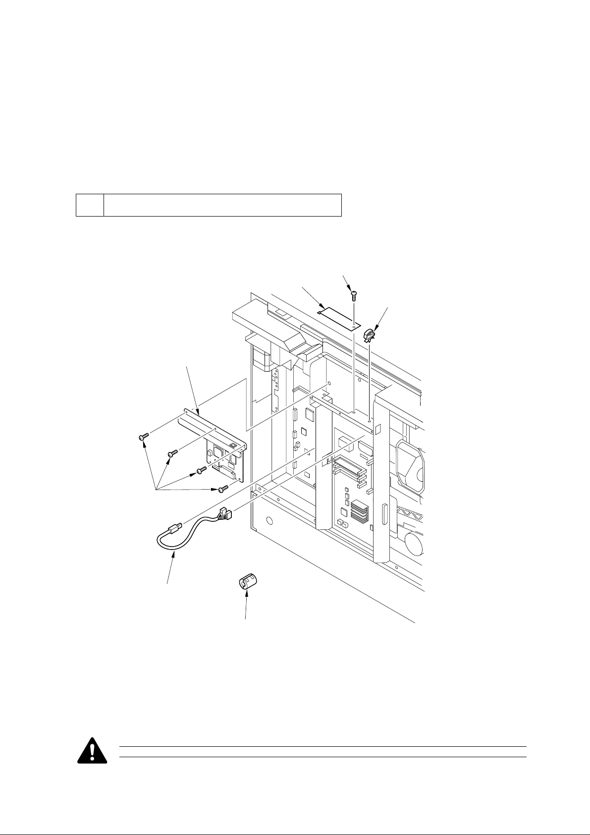
1 Unpacking and Checking the Contents
Unpack the Ethernet Network Interface Adapter iN-E5, and check its contents:
[5]
[4]
[3]
[1]
[5]
[2]
[6]
[1] Network interface adapter ......................... 1 pc.
[2] USB cable .................................................. 1 pc.
[3] Cable clamp ............................................... 1 pc.
[1]
[4] HDD face plate..........................................1 pc.
[5] Mounting screw ....................................... 5 pc.*
[6] Ring core ................................................... 1 pc.
*One of which is equipped with a washer.
F1-1
Do not touch the elements on the PCB or in the circuitry.
– 2 –
Page 2
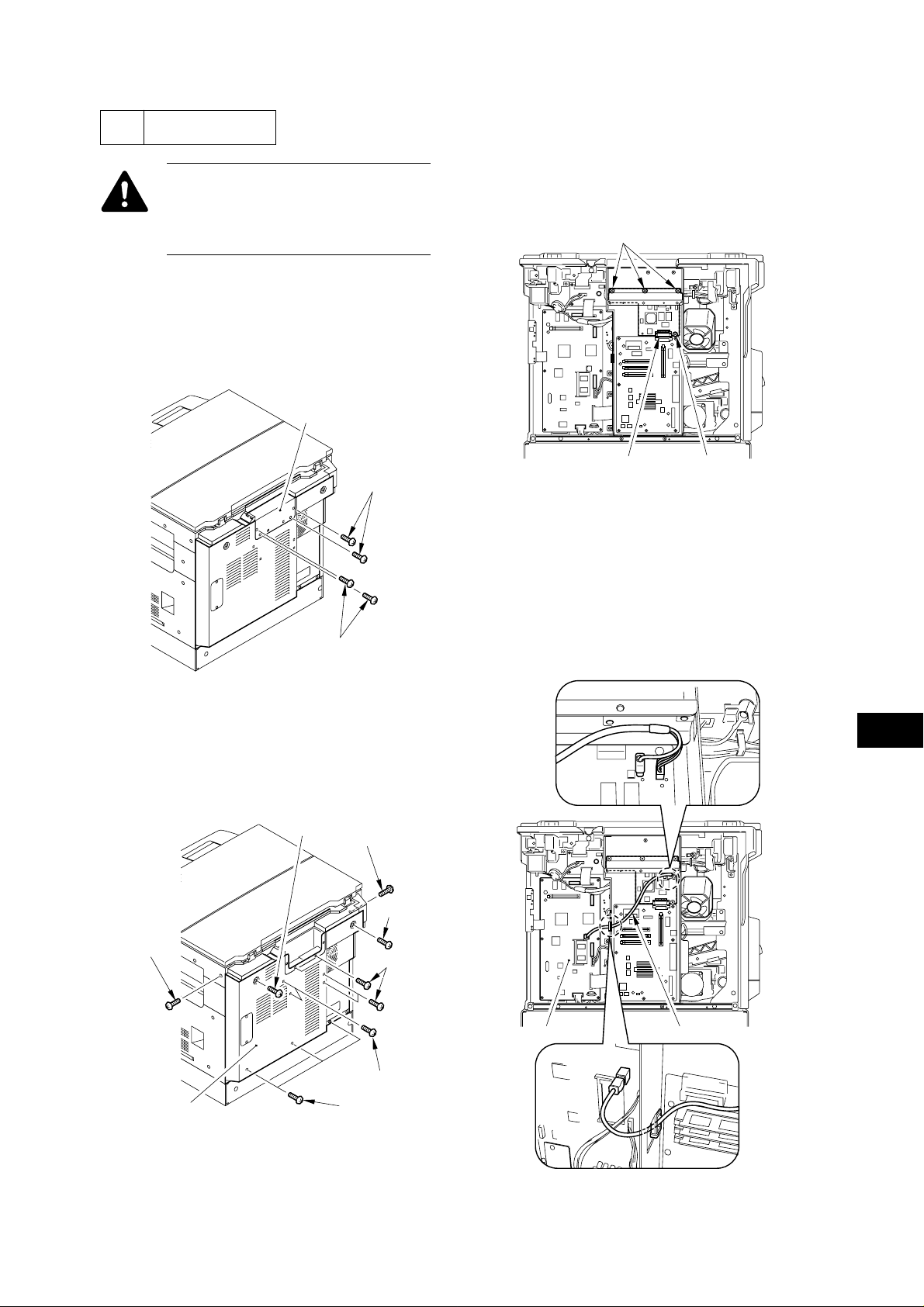
2 Installation
Be sure that the Printer Board-N1 has
already been installed to the host
machine before starting the installation
work of the Ethernet Network Adapter
iN-E5.
1) Turn off the host machine’s power switch, and
disconnect its power plug from the power outlet.
2) Remove the 4 screws [1] from the top of the
rear cover, and detach the face cover [2].
[2]
[1]
4) Connect the network interface adapter to the
connector [1] of the printer board, and secure it
in place using 4 screws [2] that come with the
adapter. (Be sure to use the screw equipped with
a washer for the PCB.)
[2]
[2][1]
F2-3
5) As shown, connect the network interface
adapter and the image processor PCB [2] with
the USB cable [1] that comes with the adapter.
At that time, be sure to keep the USB cable in
place using the cable clamp.
[1]
F2-1
3) Remove the 13 screws [1], and detach the rear
cover [2].
[1]
[1]
[1]
[1]
[1]
[1]
[1][2]
[2]
[1]
F2-2
F2-4
– 3 –
Page 3

6) Fit the cable clamp [1] that comes with the
adapter to the plate for the printer board.
[1]
F2-5
7) As shown, mount the ring core [1] that comes
with the adapter to the network cable, and
connect it to the network interface adapter. At
this time, be sure to secure the network cable
using the cable clamp fitted in step 6).
If you are not installing a hard disk (HD-
65), carry out step 8).
8) Mount the HDD face plate [2] using a screw [1]
that comes with the adapter.
[1][2]
F2-7
[1]
9) Mount the rear cover you removed in step 3).
About 10 cm
F2-6
– 4 –
Page 4

3 Making Checks After
B. Checking the Status
Installation
A. Making Initial Checks of the Network
Interface Adapter
1) Connect the power plug to the power outlet, and
turn on the host machine’s power switch; then,
check to make sure that the ERR LED indicator
on the network interface adapter goes ON,
remains ON for several seconds, and goes OFF.
ERR LNK I00 TXD RXD
Be sure that it is
not lit or blinked.
1) Go through the following to generate “TEST
PRINT” using the printer board.
In the control panel, operate as follows: System
key> Go key (so that “PAUSE” is indicated)>
Menu key (so that “TEST MENU” is indicated)>
Item key; then select “TEST PRINT”, and press the
Enter/Cancel key.
"System"key
F3-1
The LED indicators are used as follows:
RXD: green; ON during reception of data.
TXD: green; ON during transmission of data.
100: green; ON during operation at 100 Mbps;
OFF during operation at 10 Mbps.
LNK: green; ON if network connection is normal.
ERR: orange; ON and blinks if operation is faulty.
F3-2
2) Check to make sure that the notation
“ETHERNET MENU” is found in the test print
output.
If the notation “ETHERNET MENU” is not
indicated in the test print output of the printer
board, check to make sure once again that the board
is mounted correctly.
– 5 –
 Loading...