

Page 1
ADF-J1
REVISION 0
SEPT . 2001
COPYRIGHT© 2001 CANON INC. 2001 CANON ADF-J1 REV.0 SEPT. 2001 PRINTED IN JAPAN (IMPRIME AU JAPON)
FY8-13HK-000
Page 2

Application
This manual has been issued by Canon Inc. for qualified persons to learn technical
theory , installation, maintenance, and repair of products. This manual covers all localities
where the products are sold. For this reason, there may be information in this manual that
does not apply to your locality.
Corrections
This manual may contain technical inaccuracies or typographical errors due to
improvements or changes in products. When changes occur in applicable products or in
the contents of this manual, Canon will release technical information as the need arises.
In the event of major changes in the contents of this manual over a long or short period,
Canon will issue a new edition of this manual.
The following paragraph does not apply to any countries where such provisions are
inconsistent with local law.
Trademarks
The product names and company names used in this manual are the registered trademarks of the individual companies.
Copyright
This manual is copyrighted with all rights reserved. Under the copyright laws, this
manual may not be copied, reproduced or translated into another language, in whole or in
part, without the written consent of Canon Inc.
COPYRIGHT © 2001 CANON INC.
Printed in Japan
Imprimé au Japon
Caution
Use of this manual should be strictly supervised to avoid disclosure of confidential information.
COPYRIGHT© 2001 CANON INC. 20 CANON ADF-J1 REV.0 SEPT. 2001 PRINTED IN JAPAN (IMPRIME AU JAPON)
Page 3
INTRODUCTION
Memo
1 Symbols Used
This documentation uses the following symbols to indicate special information:
Symbol Description
Indicates an item of a non-specific nature, possibly classified as Note, Caution,
or Warning.
Indicates an item requiring care to avoid electric shocks.
Indicates an item requiring care to avoid combustion (fire).
REF.
Indicates an item prohibiting disassembly to avoid electric shocks or problems.
Indicates an item requiring disconnection of the power plug from the electric
outlet.
Indicates an item intended to provide notes assisting the understanding of the
topic in question.
Indicates an item of reference assisting the understanding of the topic in question.
Provides a description of a service mode.
Provides a description of the nature of an error indication.
COPYRIGHT
©
Refers to the Copier Basics Series for a better understanding of the contents.
2001 CANON INC. 2001 2001 2001 2001 CANON ADF-J1 REV.0 SEPT. 2001
i
Page 4

INTRODUCTION
2 Outline of the Manual
This Service Manual contains basic facts and figures needed to service the ADF-J1 in the
field, and it consists of the following chapters:
Chapter 1 General Description: features, specifications, methods of operation
Chapter 2 Outline of Operation: mechanical systems by function, electrical systems
in reference to principles of operation, timing of operation; construction and outline of electrical circuitry
Chapter 3 Mechanical Systems construction of mechanical systems; disassembly,
assembly, and adjustments
Chapter 4 Maintenance and Inspection:
periodically replacement parts, durables and
consumables; scheduled servicing chart
Chapter 5 Troubleshooting standards, adjustments, troubleshooting tables
Appendix: general timing chart, list of signals/abbreviations,
general circuit diagrams
For installation, refer to the Installation Procedure found in the shipping box; this manual
omits descriptions of the installation work.
ii
COPYRIGHT
©
2001 CANON INC. 2001 2001 2001 2001 CANON ADF-J1 REV.0 SEPT. 2001
Page 5

INTRODUCTION
The descriptions in this Service Manual are based on he following rules:
1. In each chapter, the uses of the function in question and its relationship to electrical and
mechanical systems are discussed and the timing of operation of its associated parts is
explained by means of outlines and diagrams.
In the diagrams, the symbol
represents a mechanical path, while the symbol
with a name next to it indicates the flow of an electric signal.
The expression “turn on the power” means turning on the power switch, closing the
front door, and closing the delivery door so that the machine will be supplied with
power.
2. In circuit diagrams (digital), a signal whose level is High is expressed as being ‘1’,
while a single whose level is Low is expressed as being ‘0’; the level of voltage, however, varies from circuit to circuit.
The machine uses CPUs, whose internal mechanisms cannot be checked in the field,
and, therefore, are not explained. In addition, the machine’s PCBs are not intended for
repairs at the user’s and, therefore, are explained by means of block diagrams: two types
are used, i.e., between sensors and inputs of PCBs equipped with a control or drive function and between outputs equipped with a control or drive function and loads; in addition, functional block diagrams are used at times.
Changes made to the machine for product improvement are communicated in the form of
a Service Information bulletin as needed. All ser vice persons are expected to go through all
service documentation including the bulletins and be equipped to respond to the needs of the
field (as by being able to identify possible causes of problems).
COPYRIGHT
©
2001 CANON INC. 2001 2001 2001 2001 CANON ADF-J1 REV.0 SEPT. 2001
iii
Page 6

CONTENTS
Contents
CHAPTER 1 GENERAL DESCRIPTION
1 Features............................................... 1-1
2 Specifications...................................... 1-2
2.1 Specifica tions ............................. 1-2
3 Names of Components........................1-3
3.1 External View............................. 1-3
3.2 Cross Section ............................. 1-4
4 Using the Machine .............................. 1-5
4.1 Routine Maintenance by the User 1-5
CHAPTER 2 OUTLINE OF OPERATION
1 Basic Construction.............................. 2-1
1.1 Outline of the Electrical Circuitry 2-1
1.2 Inputs to and Outputs from the
ADF Drive PCB......................... 2-2
2 Basic Operations ................................. 2-3
2.1 Outline ....................................... 2-3
2.2 Sequence of Operation...............2-4
2.2.1 Outline ................................. 2-4
2.2.2 Picking Up and Delivering
Originals (Single-sided original
→ Single-sided print) .......... 2-4
2.3 Detecting Originals .................... 2-5
2.3.1 Outline ................................. 2-5
2.3.2 Detecting the Presence/Absence
of an Original....................... 2-6
2.3.3 Detecting the Last Original . 2-6
2.3.4 Detecting the Size of an
Original ................................ 2-7
2.4 Picking Up and Separating an
Original .................................... 2-10
2.4.1 Basic Pickup Operation ..... 2-10
2.4.2 Separation/Pickup
Mechanism ........................ 2-13
2.4.3 Sequence of Pickup
Operation ........................... 2-19
2.4.4 Pickup Unit and the Stopper 2-1 9
2.4.5 Controlling the Feed Motor
(M1) ................................... 2-20
3 Jams .................................................. 2-21
3.1 Outline ..................................... 2-21
3.2 Jam/Error Report ...................... 2-21
3.2.1 Generating a Jam/Error
Report ................................ 2-21
3.2.2 List of Jam Codes .............. 2-22
4 Power Supply.................................... 2-23
iv
COPYRIGHT
©
2001 CANON INC. 2001 2001 2001 2001 CANON ADF-J1 REV.0 SEPT. 2001
Page 7

CHAPTER 3 MECHANICAL SYSTEMS
CONTENTS
1 Basic Construction.............................. 3-1
1.1 External Covers.......................... 3-1
1.1.1 Removing the Front Cover .. 3-2
1.1.2 Removing the Rear Cover ... 3-2
1.1.3 Removing the Feeder Cover 3-2
2 Pickup System .................................... 3-3
2.1 Separation Roller Unit ............... 3-3
2.1.1 Removing the Separation
Roller Unit ........................... 3-3
2.1.2 Mounting the Separation
Roller Unit ........................... 3-4
2.2 Separation Pad ........................... 3-5
2.2.1 Removing the Pre-Separation
Pad/Separation Pad .............. 3-5
3 Drive System....................................... 3-6
3.1 Feeder Motor .............................. 3-6
3.1.1 Removing the Feeder Motor 3-6
3.2 Drive System .............................. 3-7
3.2.1 Removing the Feeder Unit...3-7
3.2.2 Removing the Clutch ........... 3-9
3.2.3 Disassembling the Feeder
Drive Assembly ................. 3-11
3.2.4 Removing the Platen
Roller ................................. 3-12
3.2.5 Removing the Feeder
Roller ................................. 3-13
3.2.6 Remove the Feeder
Roller 2 .............................. 3-15
3.2.7 Removing the Pull-Off
Roller .................................3-16
3.2.8 Adjusting the Platen
Guide L ............................. 3-17
4 Electrical Systems............................. 3-18
4.1 ADF Driver PCB...................... 3-18
4.1.1 Removing the ADF Driver
PCB.................................... 3-18
4.2 Sensors in the Feeder Unit....... 3-18
4.2.1 Removing the Sensor Unit. 3-18
4.2.2 Removing the Sensors ....... 3-19
4.3 Sensors in the Original Pickup
Tray .......................................... 3-19
4.3.1 Removing the Original Width
Sensor ................................ 3-19
4.3.2 Mounting the Slide Guide
Gear Plate .......................... 3-20
CHAPTER 4 MAINTENANCE AND INSPECTION
1 Periodically Replaced Parts ................ 4-1
2 Durables and Consumables ................ 4-1
3 Scheduled Servicing Chart ................. 4-1
4 Replacement ....................................... 4-2
COPYRIGHT
©
2001 CANON INC. 2001 2001 2001 2001 CANON ADF-J1 REV.0 SEPT. 2001
4.1 Replacing the Feed Roller Guide
(dust-collecting tape) ................. 4-2
4.2 Replacing the Stamp .................. 4-2
v
Page 8

CONTENTS
CHAPTER 5 TROUBLESHOOTING
1 Standards and Adjustments.................5-1
1.1 Basic Adjustments...................... 5-1
1.1.1 Adjusting the Height............ 5-1
1.1.2 Adjusting the Right Angle ... 5-2
1.1.3 Adjusting the Read
Position ................................ 5-5
1.1.4 Adjusting the Ratio
Mechanism .......................... 5-6
1.1.5 Adjusting the Horizontal
Registration..........................5-7
1.1.6 Adjusting the Leading Edge
Registration........................5-10
2 Troubleshooting Malfunctions .......... 5-12
2.1 Troubleshooting Malfunctions . . 5-12
APPENDIX
2.1.1 Pickup Fault ....................... 5-12
2.1.2 The output has black lines in
sub scanning direction ....... 5-12
2.1.3 The output has blurred
images ............................... 5-14
2.1.4 The output is out of focus or
has black fogging............... 5-14
3 Arrangement of Electrical
Components ..................................... 5-15
3.1 Sensors ..................................... 5-15
3.2 Motors, Clutches, Solenoids,
PCBs, and Others ..................... 5-16
4 Self Diagnosis ................................... 5-17
4.1 Outline ..................................... 5-17
1 General Timing Charts....................... A-1
1.1 Flow-Scanning a Single-sided A4
Document .................................. A-1
2 Signal Name/Designation List ........... A-3
3 General Block Diagram ..................... A-5
4 ADF Controller Block Diagram ........ A-6
5 Jam Code List .................................... A-7
6 Special Tools List............................... A-8
7 Solvent/Grease List............................ A-8
vi
COPYRIGHT
©
2001 CANON INC. 2001 2001 2001 2001 CANON ADF-J1 REV.0 SEPT. 2001
Page 9

CHAPTER 1
GENERAL DESCRIPTION
COPYRIGHT
©
2001 CANON INC. 2001 2001 2001 2001 CANON ADF-J1 REV.0 SEPT. 2001
Page 10

Page 11

CHAPTER 1 GENERAL DESCRIPTION
1 Features
a.Exclusive Use for Stream Reading
The machine is designed for reading all originals in stream reading mode.
b.Control by the Host Machine
The machine is not equipped with a controller PCB, and is directly controlled by its host
machine.
c.Original Size Detection
The machine is able to identify the size of originals based on length (feed direction) and
width for communication to its host machine.
d.Extra-Length Mode
When extra length mode is selected, the machine will read an original as long as 1000
mm in length.
e.Mixed Original Sizes (of the same width)
The machine accepts 2 different sizes of originals*.
* Must not be of different configurations.
COPYRIGHT
©
2001 CANON INC. 2000 2000 2000 2000 CANON ADF-J1 REV.0 SEPT. 2001
1-1
Page 12

CHAPTER 1 GENERAL DESCRIPTION
2 Specifications
2.1 Specifications
Item
Method of original
pickup
Orientation of original
Placement of original
Method of original
separation
Type of original
Size of original
Original tray
Delivery assembly
Original handling
Identification of original size
Detection of residual
original
Originals of mixed sizes
Communication with
host machine
Power supply
Weight
Dimensions
Serial number
Operating environment
Temperature
Humidity
Specifications
Auto pickup/delivery
Original tray: Face-up
Original tray: Center reference
Top separation
Single-sided original:
Continuous feeding (52 to 105 g/m
Single feeding (38 to 128 g/m
Book Original:
40 mm/1.57 in height
AB: B6/A5/B5/A4/A5R/B5R/A4R/
B4/A3
Inch: STMT/LTR/LTRR/LGL/11"x 17"
Width: 148 mm/5.83 in (A5R) to 297 mm/11.7
in (A3)
Length:128 mm/5.04 in (STMT) to 432 mm/17
in (11" x 17")
50 sheets (small size)
25 sheets (large size)
50 sheets
Single-sided original
Yes (default size only)
Yes (in association with host machine)
Yes (if of same configuration)
Directly controlled by host machine
24 VDC, 5 VDC; from host machine
7.1 kg/15.6 lb (approx.)
592 x 484 x 22 mm/23.3 x 19.1 x 0.87 in (W x
D x H)
A-configuration: XGKxxxxx
Inch/A-configuration: XGJxxxxx
AB-configuration: XGHxxxxx
AB-configuration: XGLxxxxx
Same as host machine
Same as host machine
2
)
2
)
Remarks
If 432 mm/17.0 in or
2
2
or less.
2
or less.
2
or less.
.
longer, 60 to 90 g/m
In extra-length mode, as
long as 1000 mm/39.4 in.
Paper of 80 g/m
Paper of 80 g/m
Paper of 80 g/m
1-2
COPYRIGHT
©
T01-201-01
2001 CANON INC. 2000 2000 2000 2000 CANON ADF-J1 REV.0 SEPT. 2001
Page 13
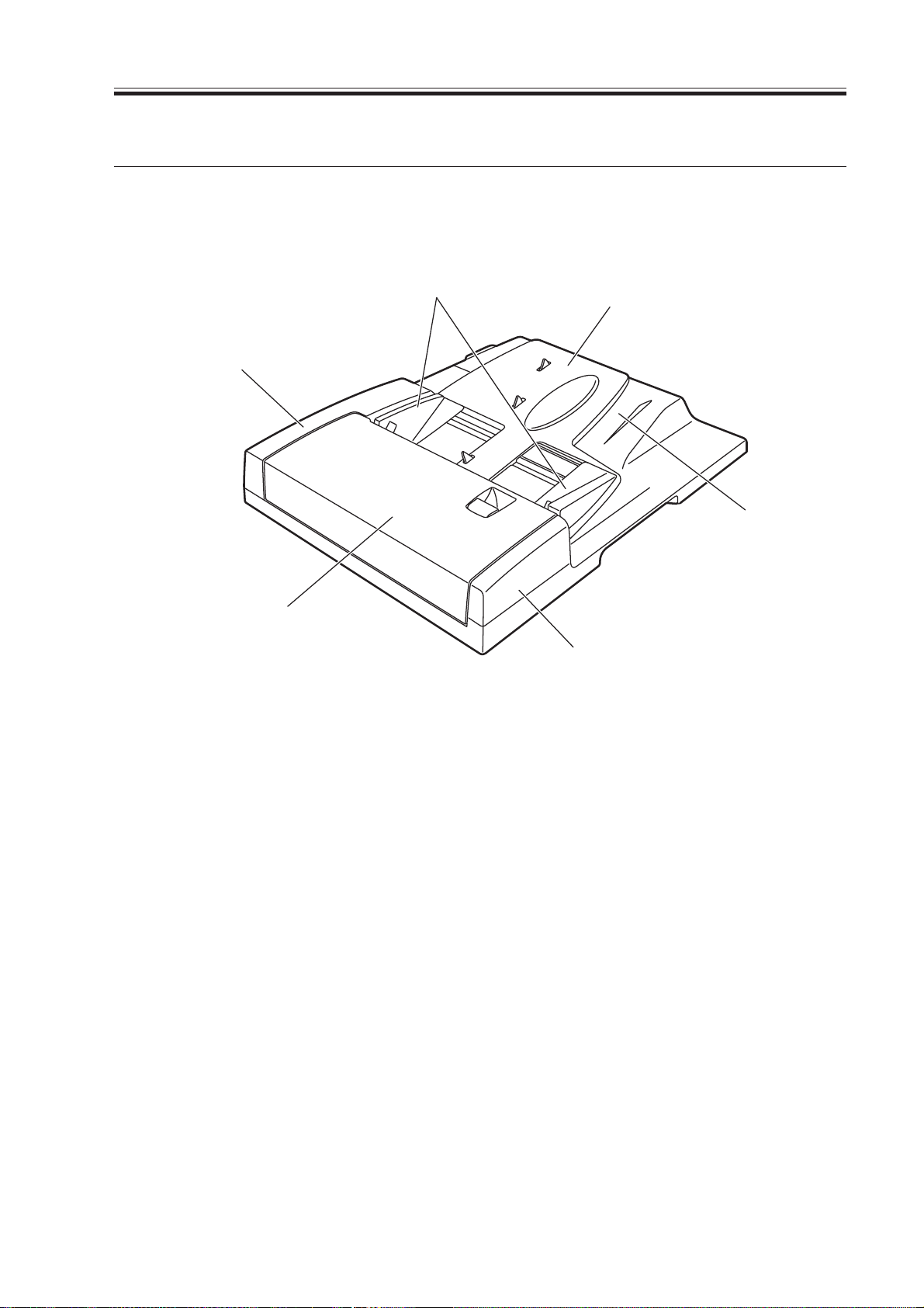
3 Names of Components
3.1 External View
CHAPTER 1 GENERAL DESCRIPTION
[2]
[1]
[3]
F01-301-01
[4]
[6]
[5]
[1] Feeder cover
[2] Rear cover
[3] Slide guide
[4] Original pickup tray
[5] Front cover
[6] Original delivery assembly
COPYRIGHT
©
2001 CANON INC. 2000 2000 2000 2000 CANON ADF-J1 REV.0 SEPT. 2001
1-3
Page 14
CHAPTER 1 GENERAL DESCRIPTION
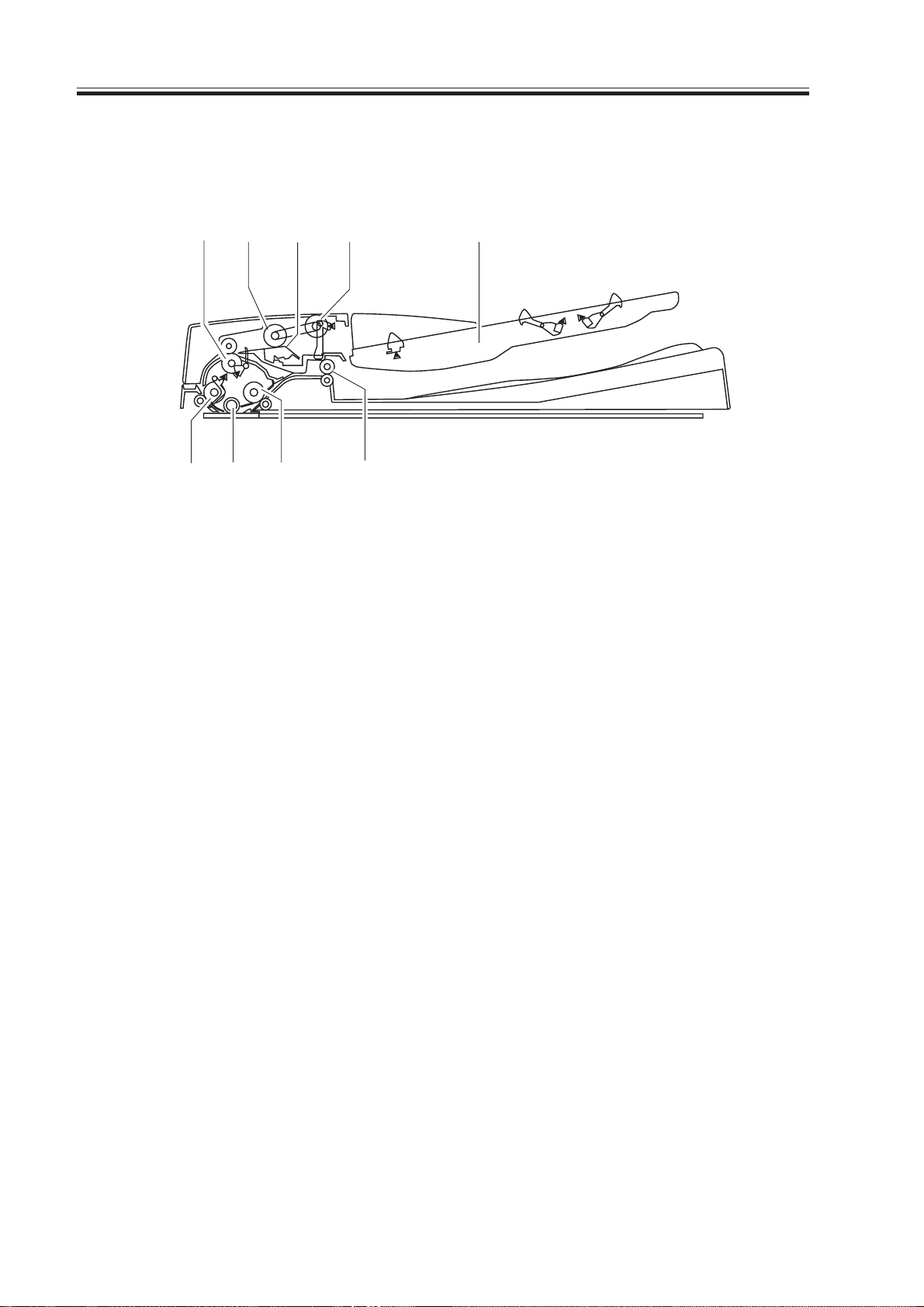
3.2 Cross Section
[1] [5]
[2]
[8] [7][9]
[3]
[4]
[6]
F01-302-01
[1] Pull-off roller
[2] Separation roller
[3] Separation pad
[4] Pickup roller
[5] Original pickup tray
[6] Delivery roller
[7] Feeding roller 2
[8] Platen roller
[9] Feeding roller 1
1-4
COPYRIGHT
©
2001 CANON INC. 2000 2000 2000 2000 CANON ADF-J1 REV.0 SEPT. 2001
Page 15
CHAPTER 1 GENERAL DESCRIPTION
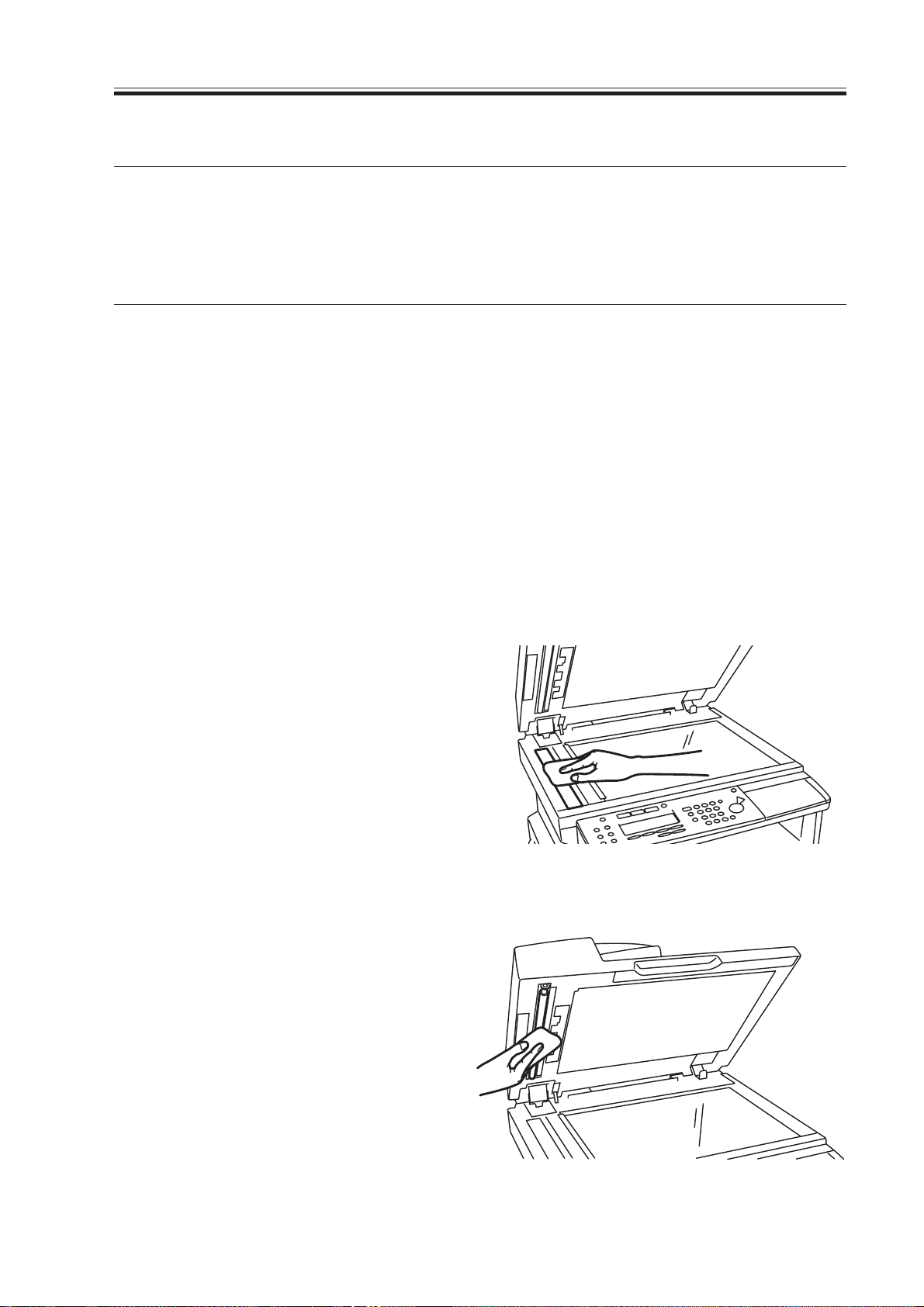
4.Using the Machine
4.1 Routine Maintenance by the User
Instruct the user to clean the following component about once a month:
Component
Copyboard glass
Copyboard glass retainer
Vertical size plate
Platen roller
White plate (copyboard
cover)
Wipe with a cloth moistened with water or alcohol; then, dry wipe.
Description
T01-401-01
To clean, go through the following:
1) Clean the copyboard glass, copyboard
glass retainer, and vertical size plate
with a cloth moistened with water; then,
dry wipe them with a dry, soft cloth.
Remarks
• Parts of the reader assembly.
• Parts of the reader assembly.
• Parts of the reader assembly.
2) Wipe the platen roller and the
copyboard cover with a cloth moistened
with water; then dry wipe them with a
dry, soft cloth.
COPYRIGHT
©
2001 CANON INC. 2000 2000 2000 2000 CANON ADF-J1 REV.0 SEPT. 2001
F01-401-01
F01-401-02
1-5
Page 16

Page 17

CHAPTER 2
OUTLINE OF OPERATION
COPYRIGHT
©
2001 CANON INC. 2001 2001 2001 2001 CANON ADF-J1 REV.0 SEPT. 2001
Page 18

Page 19
CHAPTER 2 OUTLINE OF OPERATION
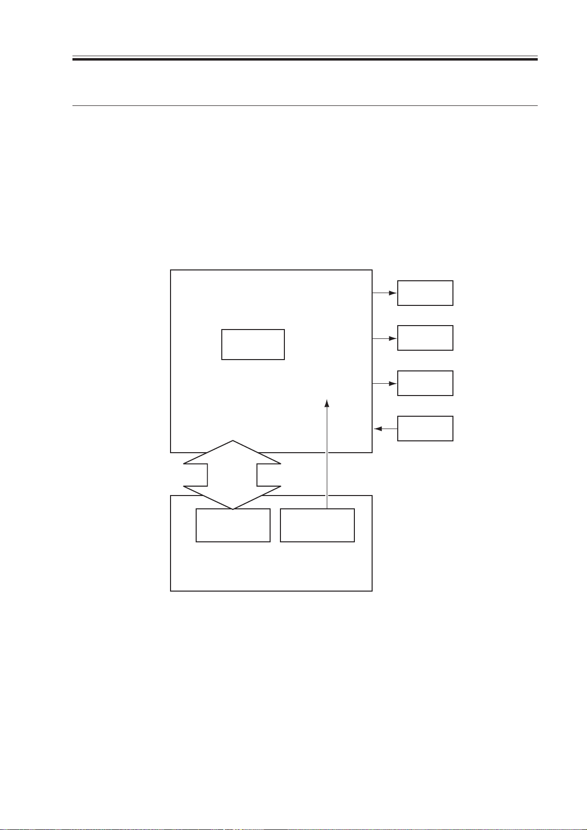
1 Basic Constr uction
1.1 Outline of the Electrical Circuitry
The machine is not equipped with a controller PCB; it, however, has a driver PCB. Its
electrical mechanisms are controlled by the controller PCB of its host machine (CPU identified as IC1).
The CPU of the host machine interprets the input signals from sensors, and sends signals
to the machine’s driver PCB to drive the loads (motor, clutch, solenoid) at such times as programmed in advance.
ADF Driver PCB
Motor
J1
Sensor
drive
signal
Controller
PCB
Driver IC
(IC1)
Power supply
Host machine
Clutch
Solenoid
+24V
Sensor
J2-1,2
PCB
COPYRIGHT
©
F02-101-01
2001 CANON INC. 2000 2000 2000 2000 CANON ADF-J1 REV.0 SEPT. 2001
2-1
Page 20
CHAPTER 2 OUTLINE OF OPERATION
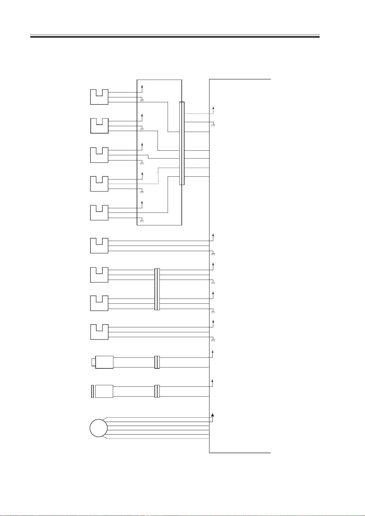
1.2 Inputs to and Outputs from the ADF Drive PCB
Inputs to and Outputs from the ADF Driver
Last original
detection sensor
Length sensor 1
Length sensor 2
Original width
sensor 1
Original width
sensor 2
Original
placement sensor
PI1
PI2
PI3
PI4
PI5
PI6
J21-3
J22-3
J23-3
J24-3
J25-3
J26-3
-2
-1
-2
-1
-1
-2
-1
-2
-1
-2
-1
-2
J102-1
-10
-12
-11
-13
-15
-14
+3.3VE
+3.3VE
+3.3VE
+3.3VE
+3.3VE
Relay PCB
J101
-7
-6
-5
-4
-3
-2
-1
J3-1
J6-1
-2
-3
-4
-5
-6
-7
-9
-8
J5-1
-2
-3
-2
-3
-4
-3
-2
LENG1
LENG2
LENG3
WID1
WID2
SET
ADF driver PCB
+3.3VE
When paper is present, '1'.
When paper is present, '1'.
When paper is present, '1'.
Detects paper width.
Detects paper width.
+3.3VS
When paper is present, '0'.
Registration sensor
Read sensor
Cover open/closed
sensor
Stamp solenoid
Pickup clutch
Feeder motor
PI7
PI8
PI9
M1
SL1
CL1
J27-3
J28-3
J31-3
-10
-12
-11
J7-1
J8-1
J4-1
-4
-6
-5
-7
-9
-8
-2
-2
-2
-3
-4
-5
-6
+3.3VE
REG
+3.3VE
READ
+3.3VE
DFCVS
+24V
STAMP_SL
+24V
CL
+24V
MOTA
MOTA*
MOTB
MOTB*
When paper is present, '1'.
When paper is present, '1'.
When the ADF cover is opened, '1'.
When '0', SL1 goes ON.
When '0', CL1 goes ON.
For details, see p. 2-20.
J30
-2
-1
-2
-1
-2
-1
-2
-1
-3
-2
-4
-6
-5
-1
-2
-1
-2
-3
J13
J201
-4
-1
-3
-1
-2
-2
-1
-3
-2
-1
2-2
COPYRIGHT
©
F02-102-01
2001 CANON INC. 2000 2000 2000 2000 CANON ADF-J1 REV.0 SEPT. 2001
Page 21
CHAPTER 2 OUTLINE OF OPERATION
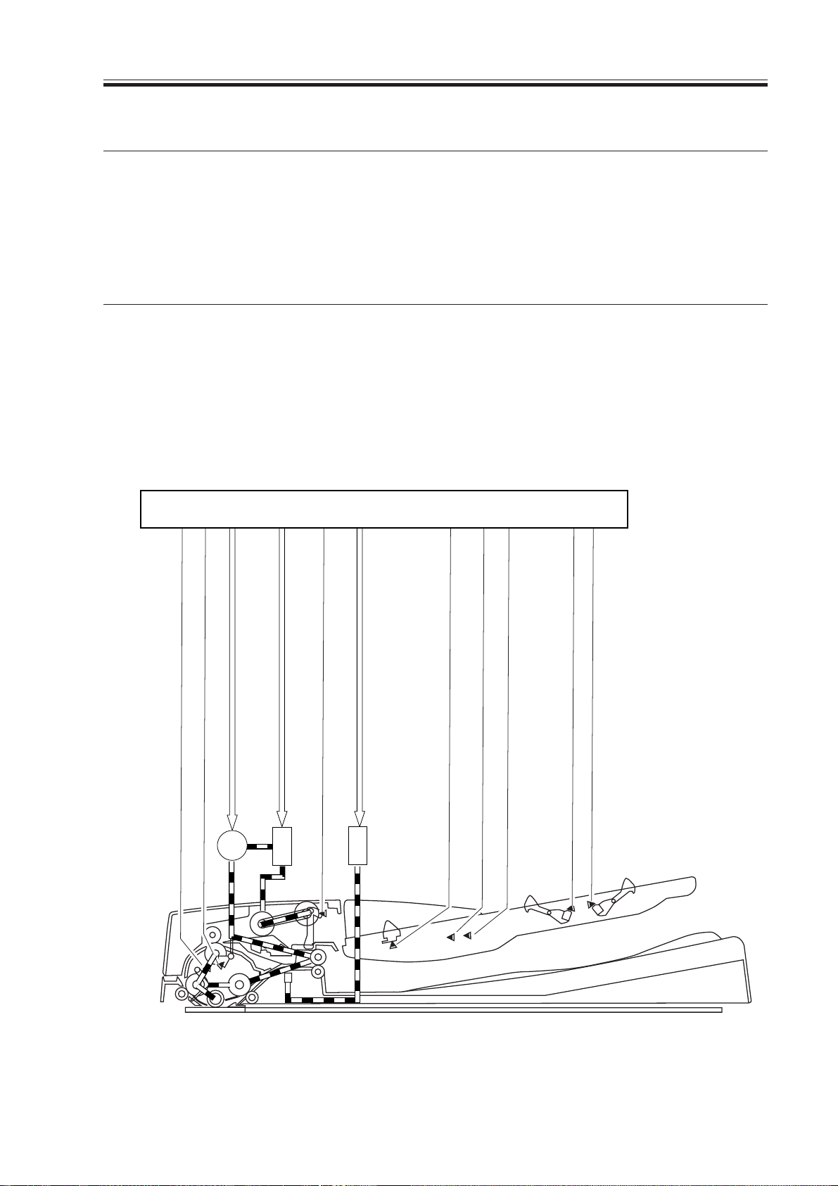
2.Basic Operations
2.1 Outline
The machine is designed exclusively for stream reading.
The machine uses a single motor to pick up and move originals.
Name (Notation)
Feeder motor (M1)
Moves originals.
T02-201-01
The following is a drive diagram of the machine:
ADF driver PCB
Function
PI8
COPYRIGHT
©
CL1
Original placement signal (SET) J5-3
PI6
Stamp solenoid drive signal (STP_SL) J7-2
SL1
Last original detection signal (LENG1) J3-3
PI1
Original width detection signal 2 (WID2) J6-4
PI5
Original width detection signal 1 (WID1) J6-3
PI4
Original detection signal (READ) J5-9
Original detection signal (REG) J5-6
PI7
Feed motor drive signal (FMOT) J4
M1
Pickup clutch drive signal (CL) J8-2
F02-201-01
2001 CANON INC. 2000 2000 2000 2000 CANON ADF-J1 REV.0 SEPT. 2001
Original length detection signal 1 (LENG2) J6-1
PI2
Original length detection signal 2 (LENG3) J6-2
PI3
2-3
Page 22
CHAPTER 2 OUTLINE OF OPERATION
2.2 Sequence of Operation
2.2.1 Outline
The machine does not possess a reversing mechanism, and picks up and delivers originals
as they are.
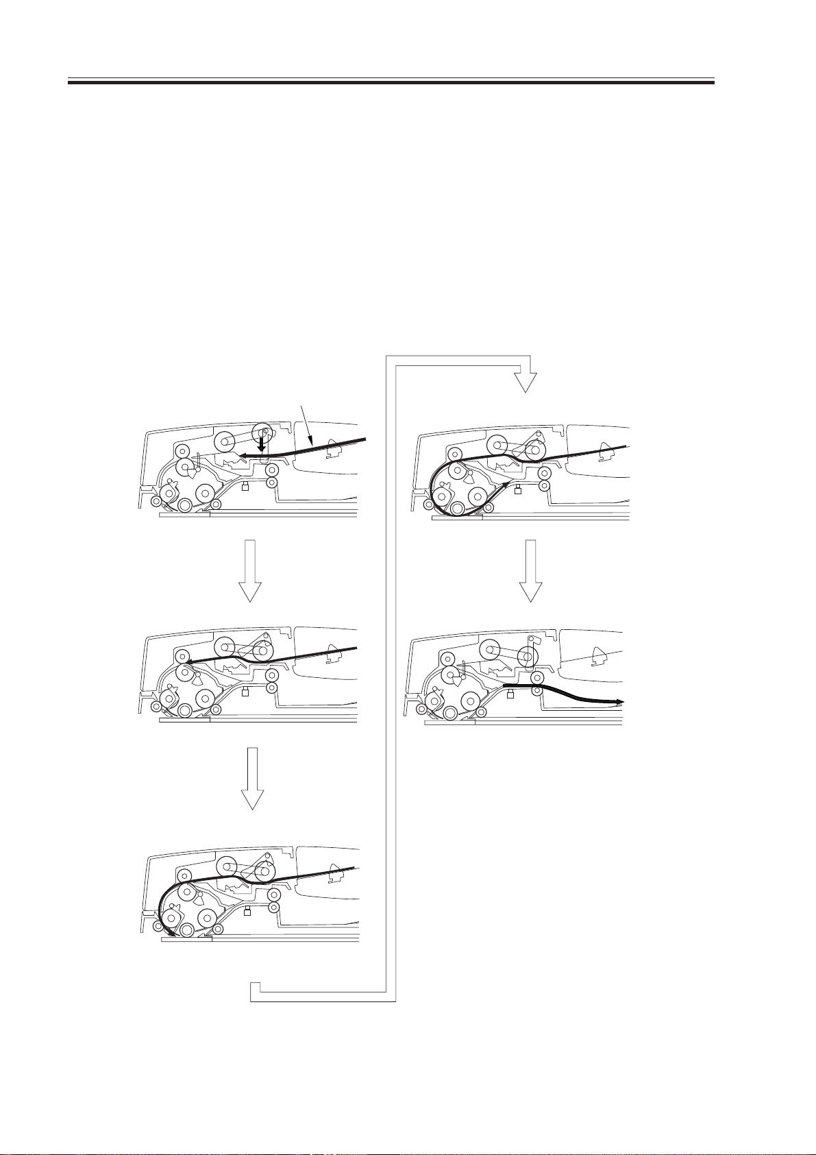
2.2.2 Picking Up and Delivering Originals
(Single-sided original → Single-sided pr int)
The machine moves the original as follows:
Original
Separation
Pickup
Reading
Delivery
2-4
Read timing detection
F02-202-01
COPYRIGHT
©
2001 CANON INC. 2000 2000 2000 2000 CANON ADF-J1 REV.0 SEPT. 2001
Page 23

CHAPTER 2 OUTLINE OF OPERATION
2.3 Detecting Originals
2.3.1 Outline
The machine possesses the following 3 original detection mechanisms:
Item
Original detection
Last original detection
Initial original size
detection
• Feed direction
• Width direction
Description
Detects the presence/absence of an original in the original pickup tray .
Determines whether the original being
fed is a last original.
Detects the length of the original placed
in the original pickup tray .
• Identification between small size and
large size
Detects the width of the original placed
in the original pickup tray .
T02-203-01
Sensor used (Notation)
Original placement sensor (PI6)
Last original sensor (PI1)
Registration sensor (PI7)
Length sensor 1/2 (PI1/PI2)
Original width sensor 1/2 (PI4/
PI5)
COPYRIGHT
©
2001 CANON INC. 2000 2000 2000 2000 CANON ADF-J1 REV.0 SEPT. 2001
2-5
Page 24
CHAPTER 2 OUTLINE OF OPERATION
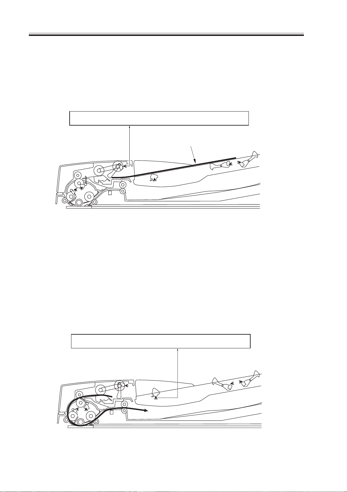
2.3.2 Detecting the Presence/Absence of an Original
The presence/absence of an original in the original tray is detected by the original placement sensor (PI6). The detecting lever operates in conjunction with the light-blocking plate.
When an original is placed in the original tray, the light from the photointerrupter is
blocked, thereby causing the original placement sensor (PI6) to generate the original placement signal (SET).
ADF driver PCB
SET
PI6
Original
F02-203-01
2.3.3 Detecting the Last Original
The last original sensor (PI1) and the registration sensor (PI7) are used to find out
whether or not the original being picked is the last original.
When the last original has been picked up and its trailing edge moves past the last original
detecting lever, the detecting lever blocks the light of the photointerrupter while operating in
association with the light-blocking plate. At this time, if the leading edge of the original is as
far as the registration sensor (PI7), the last original sensor (PI1) generates the last original
detection signal (LENG1) to communicate to the host machine that the original in question
is the last from the stack in the original tray.
2-6
PI7
COPYRIGHT
©
ADF driver PCB
LENG1
PI1
F02-203-02
2001 CANON INC. 2000 2000 2000 2000 CANON ADF-J1 REV.0 SEPT. 2001
Page 25
CHAPTER 2 OUTLINE OF OPERATION
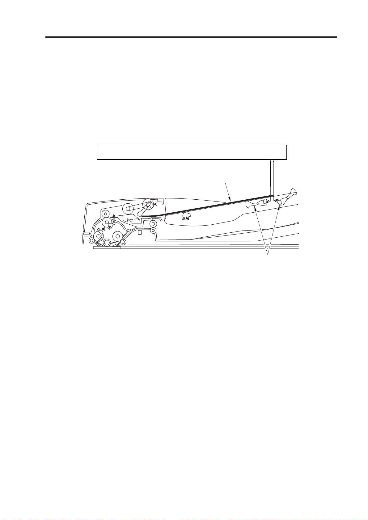
2.3.4 Detecting the Size of an Original
a.Detecting the Length in Feed Direction
The length of an original in feed direction is detect by the length sensor 1 (PI1) and the
length sensor 2 (PI2). When an original is placed in the original tray, the detecting levers of
these 2 length sensors operate in conjunction with the light-blocking plate to block the light
of the photointerrupter.
In mixed original size mode, however the length is detected based on the number of lines
read by the scanner connected to it.
ADF driver PCB
Original
LENG3
LENG2
F02-203-03
PI2
Detecting lever
PI3
COPYRIGHT
©
2001 CANON INC. 2000 2000 2000 2000 CANON ADF-J1 REV.0 SEPT. 2001
2-7
Page 26
CHAPTER 2 OUTLINE OF OPERATION
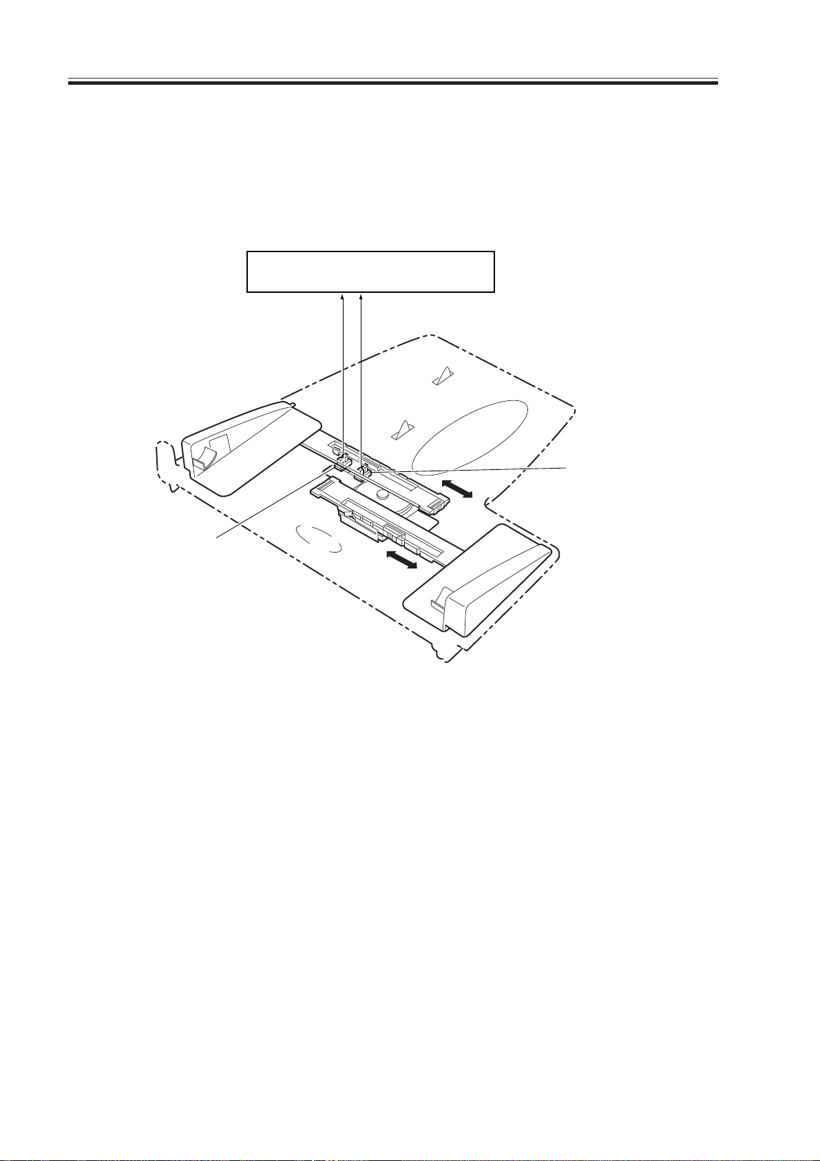
b.Detecting the Width
The width of an original is detected using the width sensor 1 (PI4) and the width sensor 2
(PI5) found in the original tray in relation to the slide guide, whose movement will block or
unblock the light of the photointerrupter.
ADF driver PCB
PI5
WID2
WID1
F02-203-04
PI4
2-8
COPYRIGHT
©
2001 CANON INC. 2000 2000 2000 2000 CANON ADF-J1 REV.0 SEPT. 2001
Page 27
CHAPTER 2 OUTLINE OF OPERATION
T02-203-02 shows the relationship between the length sensor signals and the sizes or
originals.
AB-Configured Paper
Width sensor 1 (PI4) Width sensor 2 (PI5) Length sensor 1 (PI2) AB-configuration
1 0 0 A5R
1 0 1 B5R
00 0A5
0 0 1 A4R
01 0B5
0 1 1 B4R
11 0A4
1 1 1 A3R
Inch-Configured Paper
Width sensor 1 (PI4) Width sensor 2 (PI5) Length sensor 2 (PI3) Inch-configuration
1 0 0 LTRR
1 0 1 LGL
00 0LTR
0 0 1 11”x17”
T02-203-02
PI5
PI4
PI3
PI2
COPYRIGHT
©
F02-203-05
2001 CANON INC. 2000 2000 2000 2000 CANON ADF-J1 REV.0 SEPT. 2001
2-9
Page 28
CHAPTER 2 OUTLINE OF OPERATION
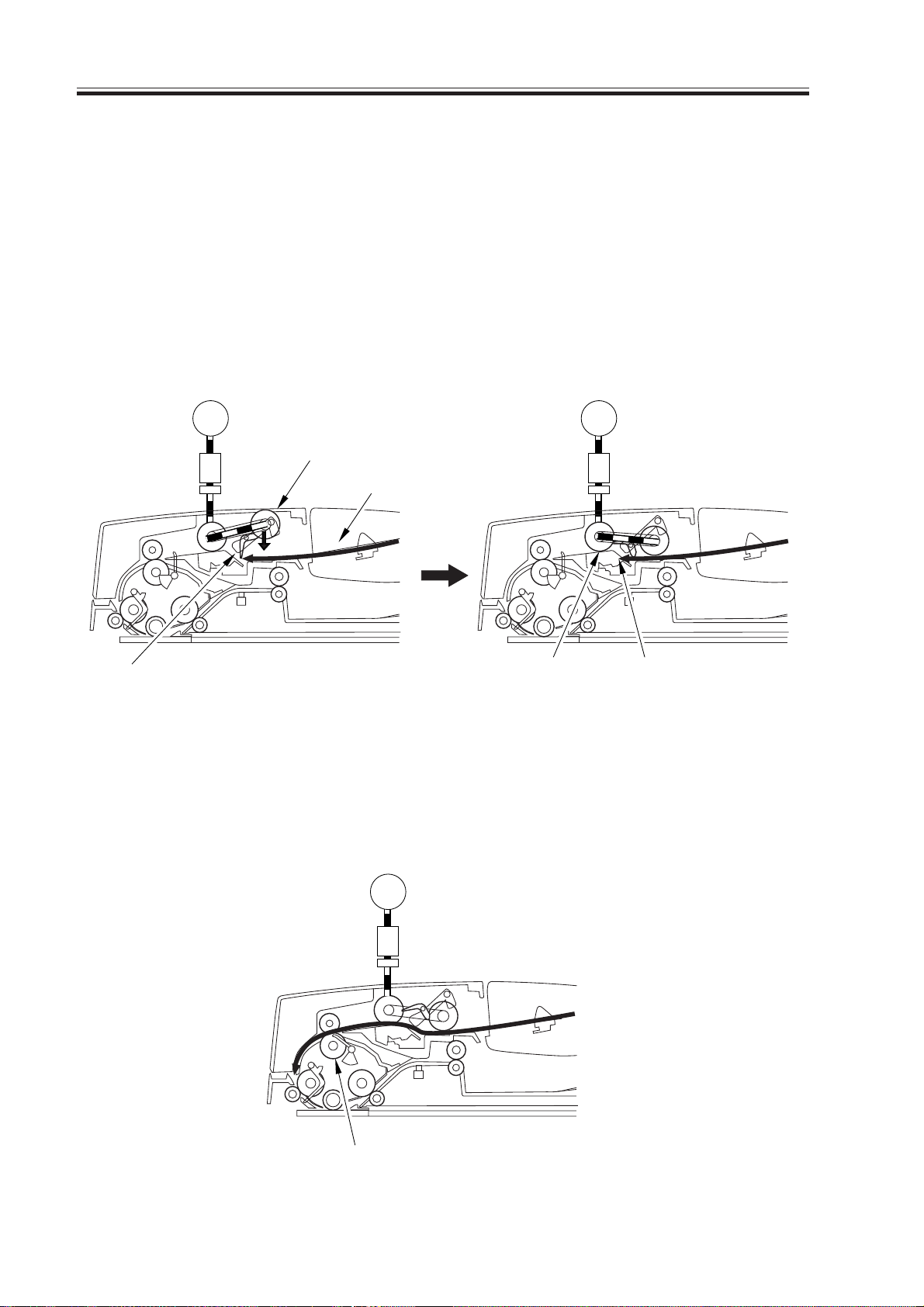
2.4 Picking Up and Separating an Original
2.4.1 Basic Pickup Operation
When an original is placed in the original tray and the Start key is pressed, the machine
will go through the following sequence:
a.Pickup
When the electromagnetic clutch goes ON and the feed motor (M1) rotates clockwise, the
pickup roller moves down, and the separation roller and the pickup roller start to rotate to
pick up an original; then, the stopper moves up in conduction.
The pre-separation pad and the separation pad serve to prevent double feeding of originals.
M1
CL1
Pre-separation pad
Stopper
M1
Pickup roller
CL1
Original
Separation pad
F02-204-01
b.Feeding
The rollers found beyond the pull-off roller rotate at a speed about 50% higher than the
separation roller. When the original reaches the pull-off roller, its movement grows faster,
thereby causing the pickup roller and the separation roller to rotate in conjunction.
2-10
Pull-off roller
COPYRIGHT
©
M1
CL1
F02-204-02
2001 CANON INC. 2000 2000 2000 2000 CANON ADF-J1 REV.0 SEPT. 2001
Page 29
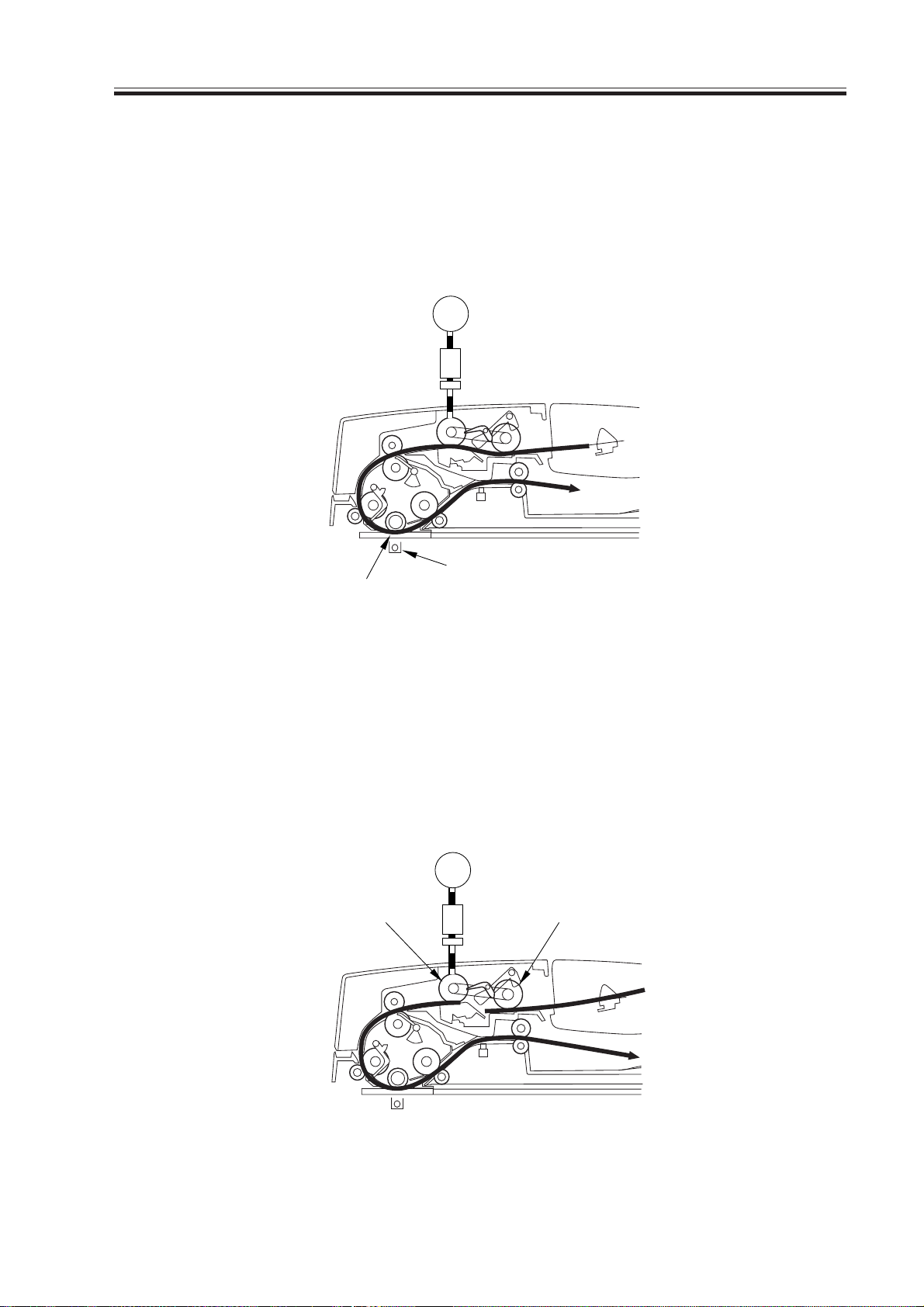
CHAPTER 2 OUTLINE OF OPERATION
c.Stream Reading and Delivery
When the leading edge of the original reaches read wait position, the machine sends the
image leading edge signal to its host machine to start stream reading; thereafter, the delivery
roller operates to delivery the original.
In stream reading, the host machine’s scanner is fixed in place, and the original is moved
over the scanner glass for scanning.
M1
CL1
Scanning lamp
Read glass
F02-204-03
d.End of Pickup for the 1st Original
When the trailing edge of the original moves past the pickup roller, the pickup roller will
come into contact with the 2nd original. However, since the separation roller is pulled by the
1st original at a higher speed than its drive shaft, the spring clutch mounted to the shaft
slips, transmitting the drive and preventing the rotation of the pickup roller and, as a result,
not picking up the 2nd original.
M1
Rating
CL1
At reset
COPYRIGHT
©
F02-204-04
2001 CANON INC. 2000 2000 2000 2000 CANON ADF-J1 REV.0 SEPT. 2001
2-11
Page 30
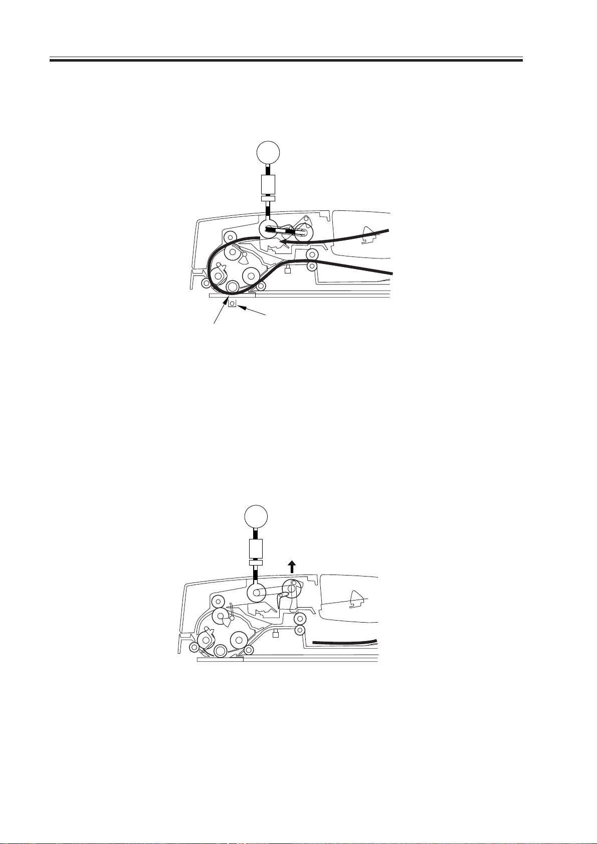
CHAPTER 2 OUTLINE OF OPERATION
e.Picking Up the 2nd Original
When the trailing edge of the original leaves the separation roller, the spring clutch trans-
mits the drive, causing the pickup roller to rotate to pick up the 2nd original.
M1
CL1
Scanning lamp
Read glass
F02-204-05
f. Returning the Pickup Roller to Standby Position
When the last original moves past the original sensor and a specific period of time passes
thereafter, the electromagnetic clutch goes OFF and the feed motor stops.
When the electromagnetic clutch goes ON and the feed motor starts to rotate in reverse,
the pickup roller is returned to standby position, at the end of which the feeder motor and
the electromagnetic clutch goes OFF.
M1
CL1
2-12
COPYRIGHT
©
F02-204-06
2001 CANON INC. 2000 2000 2000 2000 CANON ADF-J1 REV.0 SEPT. 2001
Page 31

CHAPTER 2 OUTLINE OF OPERATION
2.4.2 Separation/Pickup Mechanism
The machine uses a single stepping motor to pick up, separate, and move originals. Its
pickup assembly is equipped with 6 spring clutches which operate in various ways in relation to the direction of motor rotation as follows; the arrows in the diagrams indicates the
direction of rotation.
Down
Up
F02-204-07
a.SPCL 1 (preventing the pickup roller from moving down)
In standby, the pickup roller must be kept in up position. While the pickup roller remain
in up position, its own weight tries to force the clutch shaft to rotate clockwise; this, however, is prevented by the tightening of SPCL1, which makes a connection to the serials of
gears linked to the motor.
The drive occurring as a result of clockwise/counterclockwise rotation of the motor is
transmitted to the shaft when the clutch goes ON, and the operation of the clutch is irrelevant.
SPCL1
Pickup roller prevent down
COPYRIGHT
©
Down
Pickup roller
F02-204-08
2001 CANON INC. 2000 2000 2000 2000 CANON ADF-J1 REV.0 SEPT. 2001
2-13
Page 32

CHAPTER 2 OUTLINE OF OPERATION
b.CPCL2 (separation roller/pickup roller drive; ascent/decent movement and upper
limit of pickup roller)
Motor in Clockwise Rotation
As the spring clutch contracts, the pickup roller and the separation roller are driven; as a
result, the pickup roller is moved down to rotate.
Motor Rotating in Reverse
The pickup roller is moved up, and is held in “escape” position. If the pickup roller comes
into contact with the feeder cover, the spring clutch loosens to serve as a limiter, thereby
preventing damage.
SPCL2
Seperation roller/pickup roller drive,
Seperation roller
UP/DOWN, upper limiter
Pickup roller
Down
Up
F02-204-09
2-14
COPYRIGHT
©
2001 CANON INC. 2000 2000 2000 2000 CANON ADF-J1 REV.0 SEPT. 2001
Page 33

CHAPTER 2 OUTLINE OF OPERATION
c.Coupling
The drive from the motor is transmitted by means of a coupling, from which it may reach
the pickup roller drive shaft through SPCL3 or reach the sepapation roller and pickup roller
through SPCL4.
SPCL4
SPCL3
Pickup roller UP
Pickup roller drive shaft
Coupling
Pickup roller DOWN
seperation roller/pickup roller drive
Separation roller
Coupling
Up
Pickup roller
F02-204-10
d.SPCL3 (pickup roller ascent/movement)
Motor in Clockwise Rotation
As the spring clutch expands, the drive shaft on the separation roller shaft stops to rotate;
SPCL4 is used to drive and to move down the pickup roller.
Motor Rotating in Reverse
The spring contracts to rotate the drive shaft on the separation roller shaft, and the drive is
carried through SPCL4 to move up the pickup roller.
Down
COPYRIGHT
©
2001 CANON INC. 2000 2000 2000 2000 CANON ADF-J1 REV.0 SEPT. 2001
2-15
Page 34

CHAPTER 2 OUTLINE OF OPERATION
SPCL5
Up/Down; pressure limiter (on paper)
SPCL3
Pick roller UP
Up
F02-204-11
e.SPCL4 (pickup roller descent movement, separation roller/pic kup roller drive; one way)
Motor in Clockwise Rotation
As the spring contracts, the pickup roller is moved down; at the same time, the separation
roller and the pickup roller are driven in the direction of pickup. When paper is moved by
the pull-off roller, it picks up speed, pulling and causing the separation roller to rotate in response; at this time, the spring clutch expands so that the pickup roller drive shaft stops to
rotate, ultimately stopping the pickup roller.
Motor in Reverse Rotation
The spring clutch loosens to cut the drive.
SPCL4
Pickup roller DOWN
Separation roller
seperation roller/pickup roller drive (one-way)
2-16
COPYRIGHT
©
F02-204-12
2001 CANON INC. 2000 2000 2000 2000 CANON ADF-J1 REV.0 SEPT. 2001
Page 35

CHAPTER 2 OUTLINE OF OPERATION
f. SPCL5 (pickup roller ascent/decent; pressure limiter)
Motor in Clockwise Rotatoiin
The pickup roller is moved down (in the direction that causes the spring to loosen) and is
forced against the paper. When the pickup roller comes into contact with the paper, the
spring clutch serves as a limit to keep the pressure against the paper at a specific level.
Motor in Reverse Rotation
The pickup roller is moved up (in the direction that causes the spring to tighten).
SPCL5
Pickup roller
Pickup roller
Down
Up
F02-204-13
COPYRIGHT
©
2001 CANON INC. 2000 2000 2000 2000 CANON ADF-J1 REV.0 SEPT. 2001
2-17
Page 36

CHAPTER 2 OUTLINE OF OPERATION
g.SPCL6 (pickup roller drive; one-way)
Motor in Clockwise Rotation
The drive of the belt is transmitted to the pickup roller for rotation into pickup direction
(in the direction that causes the spring to tighten). When the paper is moved by the pull-off
roller, its speed increases, and the pickup roller is pulled by the paper to rotate in conjunction. At this time, the spring clutch loosens, and the drive to the belt is cut.
Motor in Reverse Rotation
The spring clutch loosens to cut the drive.
SPCL6
Pickup roller drive (one-way)
F02-204-14
2-18
COPYRIGHT
©
2001 CANON INC. 2000 2000 2000 2000 CANON ADF-J1 REV.0 SEPT. 2001
Page 37

2.4.3 Sequence of Pickup Operation
Start key ONOriginal set
CHAPTER 2 OUTLINE OF OPERATION
Feed motor (M1)
Pickup clutch (CL1)
Original placement
sensor (PI6)
Registration sensor
(PI7)
Read sensor (PI8)
Pickup roller
Separation roller
Other rollers
Original separated/
moved
: motor, roller in reverse.
Note 1: The speed increases when the paper is pulled by the pull-off roller.
1st original read 2nd original read Original delivered
Note 1 Note 1
F02-204-15
2.4.4 Pickup Unit and the Stopper
The pickup unit consists of a pickup roller and a separation roller. When the Start key is
pressed or the original pickup signal arrives, the feed motor (M1) rotates to move down the
pickup unit, and the pickup roller and the separation roller rotate to move the paper.
The stopper operates in conjunction with the pickup unit, and moves up. To prevent
double feeding at time of pickup, the separation pad and the separation plate are used to
make sure that sheets are separated.
M1
CL1
COPYRIGHT
©
F02-204-16
2001 CANON INC. 2000 2000 2000 2000 CANON ADF-J1 REV.0 SEPT. 2001
2-19
Page 38

CHAPTER 2 OUTLINE OF OPERATION
2.4.5 Controlling the Feed Motor (M1)
The following is a diagram of the circuit used to control the feed motor (M1). The pickup
motor is a 2-phase stepping motor, and the functions of the circuit include the following:
• turning on and off the motor.
• controlling the direction of motor operation.
• controlling the speed of motor rotation.
+24V
J4
3
1
4
5
2
6
M1
IC1
CPU
PHA
PHB
PHXA
PHXB
MAPWM
MBPWM
IC1
Motor
driver
MOT A
MOT A*
MOT B
MOT B*
Host machine
controller PCB
ADF drive PCB
F02-204-17
The motor driver (IC1) on the ADF driver PCB receives commands from the host ma-
chine, and sends drive pulses to the pick motor.
The feed motor is a stepping motor, and it controls the direction and speed of rotation by
changing the order in which the drive pulses (MOTA, MOTA*, MOTB, MOTB*) are sent
and the frequency.
Signal Description
PHA drive pulse A
PHB drive pulse B
PHXA drive pulse A (reverse phase)
PHXB drive pulse B (reverse phase)
MAPWM reference current level setting A
MBPWM reference current level setting B
2-20
COPYRIGHT
©
T02-204-1
2001 CANON INC. 2000 2000 2000 2000 CANON ADF-J1 REV.0 SEPT. 2001
Page 39

CHAPTER 2 OUTLINE OF OPERATION
3 Jams
3.1 Outline
The machine uses the sensors shown in F02-302-01 to check for original jams at such
times as stored in the ROM on the controller PCB of the host machine. A jam is identified in
reference to the presence/absence of paper over a specific sensor.
The nature of a jam may be checked by generating a jam/error report in service mode.
3.2 Jam/Error Report
3.2.1 Generating a Jam/Error Report
1) Press the User mode key “ ” and then the “#” key in sequence in the control panel to
start service mode.
2) Select ‘REPORT’ using the Arrow key (right, bottommost) in the control panel of the
host machine, and press the OK key.
As a result, a jam/error report will be generated:
NN MM/DD HH : MM hh : mm P H JJJJ CCCCCC K SSSSS
NN Serial number
MM/DD month/day of occurrence MM for moth, DD for day
HH : MM time of occurrence HH for hour, MM for minute
hh : mm time of recovery hh for recovery hour , mm for reco very minute
P location general ‘4’ indicates ADF
(‘3’ indicates host, while ‘5’ indicates finisher)
H location detail ‘1’ indicates ADF
(‘0’ indicates host, while ‘2’ indicates finisher)
JJJJ jam code jam code by 4 digits
(see T02-302-01)
CCCCCC counter reading counter reading at occurrence
K source cassette, manual feeder
SSSSS paper size paper size
COPYRIGHT
©
2001 CANON INC. 2000 2000 2000 2000 CANON ADF-J1 REV.0 SEPT. 2001
2-21
Page 40

CHAPTER 2 OUTLINE OF OPERATION
3.2.2 List of Jam Codes
The following is a list of jam codes, indicating types and related sensors.
Jam code
0001
0003
0004
0007
0009
000a
000b
0011
0012
0012
0016
Jam type
Pickup fault
Delay jam
Stationary jam
Sheet-to-sheet gap
jam
ADF open jam
Feeder cover open
jam
Stationary jam at
power-on
No paper (forced
out original)
Jam in response to
Stop key
Initialization jam
Others
Related sensor
PI7
PI7, PI8
PI7, PI8
PI8
ADF open sensor of
host machine
PI9
PI7, PI8
PI6
PI7, PI8
PI7, PI8
Condition of detection
At the start of pickup, the original does
not reach the registration sensor within a
specific period of time.
The original does not reach the sensor
within a specific period of time.
The original does not leave the sensor
within a specific period of time.
After an original is read, the next original reaches the sensor before a specific
period of time.
The ADF is opened while it is in operation.
The feeder cover is opened while the
ADF is in operation.
An original exists when the power is
tuned on.
The original set sensor is OFF at the
start of pickup.
The Stop key is pressed during operation, leaving the original inside the ADF.
The sensor detects an original at time of
initialization.
Others
2-22
PI9
PI7
PI8
COPYRIGHT
PI6
T02-302-01
F02-302-01
©
2001 CANON INC. 2000 2000 2000 2000 CANON ADF-J1 REV.0 SEPT. 2001
Page 41

CHAPTER 2 OUTLINE OF OPERATION
4 Power Supply
The following is an outline diagram of the machine’s power supply system:
The machine is supplied by its host machine with 24 V, 5 V, and 3.3 V; 24 V is used for
the motor, clutches, and solenoids; 5 v is used to drive the motor driver: and 3.3 V is used
for sensor signals.
J2
24V
1
2
24V
• Clutch
• Solenoid
Host
machine
5V
3.3V
J1
J1
A4
B11
A2
B13
B14
Motor driver
IC1
ADF driver PCB
F02-401-01
24V
3.3V
• Motor
• Sensor
COPYRIGHT
©
2001 CANON INC. 2000 2000 2000 2000 CANON ADF-J1 REV.0 SEPT. 2001
2-23
Page 42

Page 43

CHAPTER 3
MECHANICAL SYSTEMS
COPYRIGHT
©
2001 CANON INC. 2001 2001 2001 2001 CANON ADF-J1 REV.0 SEPT. 2001
Page 44

Page 45

1 Basic Construction
CHAPTER 3 MECHANICAL SYSTEMS
1.1 External Covers
[1] Front cover
[2] Rear cover
[3] Feeder cover
[4] Original pickup tray
[5] Original delivery assembly
[6] Slide guide
Remove the covers as necessary as follows
when cleaning, checking, or repairing the
inside of the machine:
[2]
[3]
[6]
[4]
[5]
[1]
F03-101-01
COPYRIGHT
©
2001 CANON INC. 2000 2000 2000 2000 CANON ADF-J1 REV.0 SEPT. 2001
3-1
Page 46

CHAPTER 3 MECHANICAL SYSTEMS
1.1.1 Removing the Front Cover
1) Open the feeder cover[1], and remove
the 2 screws [2]; then, detach the front
cover.
1.1.2 Removing the Rear Cover
1) Open the feeder cover, and remove the 2
screws [1]; then, detach the rear cover.
[2]
[1]
F03-101-02
[1]
1.1.3 Removing the Feeder Cover
1) Remove the front cover.
2) Remove the screw [1] and the positioning pin [2]; then, detach the feeder
cover [3].
[1]
F03-101-03
[3]
[2]
3-2
COPYRIGHT
©
[1]
F03-101-04
2001 CANON INC. 2000 2000 2000 2000 CANON ADF-J1 REV.0 SEPT. 2001
Page 47

2 Pickup System
2.1 Separation Roller Unit
2.1.1 Removing the Separation Roller Unit
1) Remove the feeder cover.
2) Remove 4 screws [1]; then, detach the
feeder cover inside cover [2].
[1]
CHAPTER 3 MECHANICAL SYSTEMS
[1]
3) Remove the two shutter [1].
4) Remove the resin E-ring [2]; then, while
holding down the rear of the drive shaft,
detach the separation roller unit [3].
[3]
[2]
[2]
F03-201-01
[1]
F03-201-02
COPYRIGHT
©
Do not disassemble the separation roller unit any further. It
must be replaced with all components as shown; any further
assembly can deform the spring
of the spring clutch.
F03-201-03
2001 CANON INC. 2000 2000 2000 2000 CANON ADF-J1 REV.0 SEPT. 2001
3-3
Page 48

CHAPTER 3 MECHANICAL SYSTEMS
2.1.2 Mounting the Separation Roller Unit
1) Mount the separation roller unit [1].
[1]
F03-201-04
2) Mount the stopper arm [2] in the orientation indicated.
3) Mount the feeder cover inside cover.
[2]
F03-201-05
3-4
COPYRIGHT
©
2001 CANON INC. 2000 2000 2000 2000 CANON ADF-J1 REV.0 SEPT. 2001
Page 49

CHAPTER 3 MECHANICAL SYSTEMS
2.2 Separation Pad
2.2.1 Removing the Pre-Separation Pad/Separation Pad
1) Open the feeder cover.
2) Remove the 2 screws [1], and detach the
pre-separation pad [2] and the separation pad [3].
[1]
[3]
[2]
3) Slide the separation pad [3] to detach in
the direction indicated.
Take care not to lose the spring [4] attached to the bottom of the separation
pad.
F03-202-01
[3]
[4]
F03-202-02
COPYRIGHT
©
2001 CANON INC. 2000 2000 2000 2000 CANON ADF-J1 REV.0 SEPT. 2001
3-5
Page 50

CHAPTER 3 MECHANICAL SYSTEMS
3 Drive System
3.1 Feeder Motor
3.1.1 Removing the Feeder Motor
1) Remove the rear cover.
2) Disconnect the connector [1].
3) Remove the tension spring [2].
4) Remove the 2 fixing screws [3], and detected feeder motor.
[1]
[2]
F03-301-01
[3]
3-6
COPYRIGHT
©
2001 CANON INC. 2000 2000 2000 2000 CANON ADF-J1 REV.0 SEPT. 2001
Page 51

3.2 Drive System
3.2.1 Removing the Feeder Unit
If you must replace the components of the
feeder unit, replace the feeder unit as
shown:
If you have removed the feeder
REF.
1) Remove the ADF from its host machine.
2) Remove the rear cover, front cover, and
feeder cover.
3) Disconnect the 5 connectors [1], and
remove the grounding fixing screw [2].
unit, you must adjust the gap L
of the platen guide after mounting it back .(See p. 3-17.)
CHAPTER 3 MECHANICAL SYSTEMS
4) Remove the screw [4], and detach the
original placement sensor [5]; then, detach the original pickup tray [6].
[1]
F03-302-01
[6]
F03-302-02
[2]
[4]
[5]
COPYRIGHT
©
2001 CANON INC. 2000 2000 2000 2000 CANON ADF-J1 REV.0 SEPT. 2001
3-7
Page 52

CHAPTER 3 MECHANICAL SYSTEMS
5) Remove the 8 screws [1].
6) Remove the 2 screws [2].
[A]
[1]
F03-302-03
When you install the feeder
unit, tighten the 3 screws [A] at
first, then tighten the other
screws.
7) Remove the feeder unit.
If you try to remove the feeder
unit without detaching the ADF
from its host machine, the ADF
will shift up. Keep this in mind.
[A]
[2]
F03-302-04
3-8
COPYRIGHT
©
F03-302-05
2001 CANON INC. 2000 2000 2000 2000 CANON ADF-J1 REV.0 SEPT. 2001
Page 53

3.2.2 Removing the Clutch
1) Remove the feeder unit.
2) Remove the 2-resin E-rings [1].
3) Shift the gear [2] toward the rear, and
detach the parallel pin [3].
CHAPTER 3 MECHANICAL SYSTEMS
[1]
[3]
[2]
F03-302-06
4) Remove the clutch together with its
shaft.
The machine’s clutch must be
replaced together with its shaft;
do not disassemble it any further.
When installing the clutch,
match the stop assembly [1]
agdinst the fixing plate [2].
[2]
[1]
F03-302-07
COPYRIGHT
©
2001 CANON INC. 2000 2000 2000 2000 CANON ADF-J1 REV.0 SEPT. 2001
3-9
Page 54

CHAPTER 3 MECHANICAL SYSTEMS
If you have removed the clutch
from its shaft, go through the
following when mounting it
back: fit the spring [1] of the
spring clutch into the opening in
the clutch spring fixing plate
[2], and match the stop assembly [3] against the fixing plate
[4].
When securing the clutch in
place with the grip ring [1], be
sure to allow a gap of 0.2 mm
between the grip ring and the
clutch itself.
[2]
F03-302-08
[1]
[4]
[3]
0.2mm
[1]
F03-302-09
3-10
COPYRIGHT
©
2001 CANON INC. 2000 2000 2000 2000 CANON ADF-J1 REV.0 SEPT. 2001
Page 55

CHAPTER 3 MECHANICAL SYSTEMS
[1]
[1]
[2]
3.2.3 Disassembling the Feeder Drive Assembly
1) Remove the feeder unit.
2) Remove the harness and the harness
guide.
3) Remove the resin E-ring [1], and detach
the pulley [2].
[2]
[1]
F03-302-10
4) Remove the 3 screws [1], and detach the
feeder rear plate [2].
F03-302-11
COPYRIGHT
©
2001 CANON INC. 2000 2000 2000 2000 CANON ADF-J1 REV.0 SEPT. 2001
3-11
Page 56

CHAPTER 3 MECHANICAL SYSTEMS
3.2.4 Removing the Platen Roller
1) Remove the feeder unit.
2) Turn over the feeder unit, and remove
the screw [1]; then, detach the platen
guide R [2].
Do not remove the platen guide
L [3].
3) Remove the resin E-ring [1] at the front;
then, detach the pulley [2], belt [3], and
bushing [4].
4) Remove the resin E-ring [5] at the rear,
and detach the bushing [6].
[2]
[2]
[3]
[1]
F03-302-12
[4]
5) Remove the platen roller [1] as shown.
[1]
[5][6]
[3]
F03-302-13
[1]
3-12
COPYRIGHT
©
F03-302-14
2001 CANON INC. 2000 2000 2000 2000 CANON ADF-J1 REV.0 SEPT. 2001
Page 57

3.2.5 Removing the Feeder Roller
1) Remove the feeder unit.
2) Remove the platen guides L and R and
the platen roller.
3) Remove the resin E-ring [1]; then, detach the pulley [2] and the bearing [3].
CHAPTER 3 MECHANICAL SYSTEMS
[3]
[2]
[1]
F03-302-15
4) Loosen the screw [1], and detach the
spring [2] of the belt tensioner.
5) Remove the resin E-ring [1]; then, detach the pulley [2] and the bushing [3].
[1] [2]
F03-302-16
COPYRIGHT
©
F03-302-17
2001 CANON INC. 2000 2000 2000 2000 CANON ADF-J1 REV.0 SEPT. 2001
[3]
[2]
[1]
3-13
Page 58

CHAPTER 3 MECHANICAL SYSTEMS
5) Remove the resin E-ring [1], and detach
the feeder roller as shown.
[1]
F03-302-18
3-14
COPYRIGHT
©
2001 CANON INC. 2000 2000 2000 2000 CANON ADF-J1 REV.0 SEPT. 2001
Page 59

3.2.6 Remove the Feeder Roller 2
1) Remove the feeder unit.
2) Remove the platen guides L and R, and
remove the platen roller.
3) Remove resin E-ring [1]; then, detach
the gear [2] and the bushing [3].
CHAPTER 3 MECHANICAL SYSTEMS
[1]
[3]
[2]
F03-302-19
4) Loosen the 2 screws [1], and detach the
2 springs [2] of the belt tensioner.
5) Remove the resin E-ring [1]; then, detach the pulley [2] and the busing [3].
6) Remove the feede roller 2.
[2]
[1]
F03-302-20
COPYRIGHT
©
F03-302-21
2001 CANON INC. 2000 2000 2000 2000 CANON ADF-J1 REV.0 SEPT. 2001
[3]
[2]
[1]
3-15
Page 60

CHAPTER 3 MECHANICAL SYSTEMS
[1]
[2]
3.2.7 Removing the Pull-Off Roller
1) Remove the feeder unit.
2) Remove the feeder motor.
3) Remove the feeder drive assembly.
4) Remove the platen roller, feeding roller
1, and feeding roller 2.
5) Remove the resin E-ring [1] and the
bushing [2].
6) Remove the 2 resin E-rings [1]; then,
detach the 2 pulleys [2], bushing [3],
and parallel pin [4].
[1]
[2]
F03-302-22
7) Remove the 3 screws [1], and shift the
plate [2] to the front.
8) Shift the pull-off roller to the front, and
pull it off.
[1]
[2]
[3]
[4]
[2]
[1]
F03-302-23
3-16
COPYRIGHT
©
F03-302-24
2001 CANON INC. 2000 2000 2000 2000 CANON ADF-J1 REV.0 SEPT. 2001
Page 61

3.2.8 Adjusting the Platen Guide L
[1]
If you have removed the pickup unit or the
platen guide L, be sure to adjust the gap between the platen guide L and the frame of
the machine after mounting it back.
1) Open the ADF, and loosen the 2 fixing
screws [1] of the platen guide.
CHAPTER 3 MECHANICAL SYSTEMS
F03-302-25
2) Fit a gap gauge (special tool; with a gap
of 1.4 mm) [4] in the gap between the
platen guide L [2] and the frame [3] of
the machine; and tighten the 2 screws
[1] while butting the gauge against the
platen guide [4] as shown in the figure.
[1]
[2]
[3]
[4]
[2]
COPYRIGHT
©
[3]
F03-302-26
2001 CANON INC. 2000 2000 2000 2000 CANON ADF-J1 REV.0 SEPT. 2001
[4]
3-17
Page 62

CHAPTER 3 MECHANICAL SYSTEMS
4 Electrical Systems
4.1 ADF Driver PCB
4.1.1 Removing the ADF Driver PCB
1) Remove the rear cover.
2) Disconnect all connectors from the ADF
driver PCB.
3) Remove the 2 screws [1], and detach the
ADF driver PCB.
[1]
4.2 Sensors in the Feeder Unit
4.2.1 Removing the Sensor Unit
1) Remove the feeder unit.
2) Remove the platen guide R.
3) Remove the platen roller.
4) Remove the 2 screws [1], and detach the
sensor unit [2].
[1]
F03-401-01
[2]
F03-402-01
[1]
3-18
COPYRIGHT
©
2001 CANON INC. 2000 2000 2000 2000 CANON ADF-J1 REV.0 SEPT. 2001
Page 63

4.2.2 Removing the Sensors
1) Disconnect the connector.
2) Remove the registration sensor [1] and
the read sensor [2].
CHAPTER 3 MECHANICAL SYSTEMS
4.3 Sensors in the Original Pickup Tray
4.3.1 Removing the Original Width Sensor
1) Remove the front cover.
2) Raise the original pickup tray.
3) Remove the 3 screws [1], and detach the
lower cover [2].
[2]
[2]
F03-402-02
[1]
[1]
[1]
COPYRIGHT
©
F03-403-01
2001 CANON INC. 2000 2000 2000 2000 CANON ADF-J1 REV.0 SEPT. 2001
3-19
Page 64

CHAPTER 3 MECHANICAL SYSTEMS
4) Remove the 2 screws [1], and detach the
slide guide gear plate [2].
5) Remove the original width sensor 1 [3]
and the original width sensor 2 [4].
4.3.2 Mounting the Slide Guide Gear Plate
1) Spread out the slide guide [1] fully.
2) Mount the slide guide gear plate while
matching the top and bottom marking [2] of the gear and the
[3] of the front/rear slide guide.
marking
[2]
[1]
F03-403-02
[3]
[3]
[4]
[2]
3-20
COPYRIGHT
©
[1]
[3]
[2]
F03-403-03
2001 CANON INC. 2000 2000 2000 2000 CANON ADF-J1 REV.0 SEPT. 2001
Page 65

CHAPTER 4
MAINTENANCE AND INSPECTION
COPYRIGHT
©
2001 CANON INC. 2001 2001 2001 2001 CANON ADF-J1 REV.0 SEPT. 2001
Page 66

Page 67

CHAPTER 4 MAINTENANCE AND INSPECTION
1 Periodically Replaced Parts
The machine does not have parts that must be replaced on a periodical basis.
2 Durables and Consumables
The machine does not have parts that may require replacement because of wear or dam-
age once or more during the period of product warranty.
3 Scheduled Ser vicing Char t
The machine does not have parts that require periodical servicing.
COPYRIGHT
©
2001 CANON INC. 2000 2000 2000 2000 CANON ADF-J1 REV.0 SEPT. 2001
4-1
Page 68

CHAPTER 4 MAINTENANCE AND INSPECTION
4 Replacement
4.1 Replacing the Feed Roller Guide (dust-collecting tape)
1) Open the ADF.
2) Remove the 2 screws [1], and remove
the feed roll guide [2].
3) Mount the new feed roll guide.
[2]
[1]
4.2 Replacing the Stamp
1) Open the ADF cover and the separation
guide.
2) Using tweezes, remove the stamp.
3) Using tweezers, mount the new stamp.
Be sure that the stamp is oriented so
that the side with faces up.
F04-401-01
F04-402-01
4-2
Be sure to fit it until a click is
heard; otherwise, jams can occur.
COPYRIGHT
©
2001 CANON INC. 2000 2000 2000 2000 CANON ADF-J1 REV.0 SEPT. 2001
Page 69

CHAPTER 5
TROUBLESHOOTING
COPYRIGHT
©
2001 CANON INC. 2001 2001 2001 2001 CANON ADF-J1 REV.0 SEPT. 2001
Page 70

Page 71

CHAPTER 5 TROUBLESHOOTING
1 Standards and Adjustments
1.1 Basic Adjustments
Be sure to perform basic adjustments of the machine in the following order:
[1] Height
[2] Right angle
[3] Read position
[4] Ratio
[5] Horizontal registration
[6] Leading edge registration
1.1.1 Adjusting the Height
1) Check to see if the gap between the
copyboard glass of the host machine
and the copyboard stop assembly [1] on
the pickup side is 0.1 ± 0.05 mm when
the ADF is closed (approximately a
single sheet of 64 g/m
2
paper may be
inserted).
At the same time, check also that the
copyboard stop assembly [2] on the
pickup front side is in contact with the
copyboard glass. (Use a sheet of paper
to check.)
t=0.1 0.05mm
[3]
[1]
[2]
[If Not As Indicated]
1) If one side is not in contact, turn the
height adjusting bolt [3] on the left
COPYRIGHT
©
2001 CANON INC. 2000 2000 2000 2000 CANON ADF-J1 REV.0 SEPT. 2001
F05-101-01
5-1
Page 72

CHAPTER 5 TROUBLESHOOTING
hinge to make adjustments.
2) If the front side is not in contact, give
the height adjusting plate [1] of the
right hinge a 90º turn, and then adjust
the left hinge.
[1]
• If the front is not in contact, tighten
the adjusting screw.
• If the rear is not in contact, loosen the
adjusting screw.
1.1.2 Adjusting the Right Angle
Check the angle between the scanner of the
host machine and the direction of feed of
the machine, and make adjustments as necessary.
1) Using A4 or LTR paper, prepare a test
chart as shown.
F05-101-02
10mm
10mm
Right
angle
10mm
10mm
5-2
COPYRIGHT
©
F05-101-03
2001 CANON INC. 2000 2000 2000 2000 CANON ADF-J1 REV.0 SEPT. 2001
Page 73

2) Place the test chart in the original tray,
and make a Direct print.
3) Place the test chart over the output obtained in step 2), and check the angle of
the image.
A ≤ 1mm
B ≤ 1mm
CHAPTER 5 TROUBLESHOOTING
A
Feed direction
Separate
paper
Check the right angle by referring to the lines on the leading
edge.
Output obtained in step 2
B
Feed direction
Separate
paper
Output obtained in step 2)
F05-101-04
COPYRIGHT
©
2001 CANON INC. 2000 2000 2000 2000 CANON ADF-J1 REV.0 SEPT. 2001
5-3
Page 74

CHAPTER 5 TROUBLESHOOTING
[If Not As Indicated]
1) Loosen the locking nut [2] on the angle
adjusting screw [1] found at the rear of
the right hinge unit.
2) Turn the angle adjusting screw [1] to
adjust the angle.
3) Tighten the locking nut [2] to secure it
in place.
4) Make a print of the test chart once again
to see that the image is as indicated.
[1]
[2]
F05-101-05
[3]
0.4 mm/interval
REF.
A marking [3] is provided on
the right hinge assembly (bottom of the ADF); a shift over a
single interval will cause a slant
of about 0.4 mm in an image.
F05-101-06
5-4
COPYRIGHT
©
2001 CANON INC. 2000 2000 2000 2000 CANON ADF-J1 REV.0 SEPT. 2001
Page 75

1.1.3 Adjusting the Read P osition
Adjust the stream read position of the host
machine in relation to the read position of
the ADF .
1) Turn on the host machine, and press the
User Mode key “
key in sequence in its control panel to
start service mode.
2) Press the Arrow key in the control panel
of the host machine so that “TEST
MODE” is indicated.
3) Press the OK key.
4) Press “2” on the keypad so that “2.
CCD TEST” is indicated.
5) Press ‘3’ on the keypad so that “CS POS
ADJ (ADF)” is indicated.
The scanner starts scanning operation;
in about 5 sec, auto adjustment ends. If
“OK” is indicated, end the work; if
“NG” is indicated, repeat the foregoing
steps.
” and then the “#”
CHAPTER 5 TROUBLESHOOTING
If auto adjustment fails, clean
the platen roller of the ADF and
the copyboard glass of the host
machine; then, execute auto adjustment once again. If it still
fails, suspect a fault in the host
machine.
COPYRIGHT
©
2001 CANON INC. 2000 2000 2000 2000 CANON ADF-J1 REV.0 SEPT. 2001
5-5
Page 76

CHAPTER 5 TROUBLESHOOTING
1.1.4 Adjusting the Ratio Mechanism
Adjust the feed speed used to move originals, thereby adjusting the length of images
in feed direction.
1) Using A4 or LTR paper, prepare a test
chart as shown.
2) Place the test chart in the original tray,
and make a Direct print.
3) Check to see if the distance A on the
test chart and the distance B in the image obtained in step 2 ) are as follows:
A ≤ 1mm
B ≤ 1mm
Feed direction
Output obtained in step 2)
10mm
10mm
Right
angle
10mm
F05-101-07
Test chart
Test chart
10mm
A
[If Not As Indicated]
Use service mode of the host machine to
make adjustments:
1) Press the User Mode key “
” and the
“#” key in the control panel in order to
start service mode.
Feed direction
Output obtained in step 2)
B
F05-101-08
5-6
COPYRIGHT
©
2001 CANON INC. 2000 2000 2000 2000 CANON ADF-J1 REV.0 SEPT. 2001
Page 77

2) Operate as follows on the Service Mode
screen:
• Using the Arrow key, select “#6 SCANNER”; then, press the OK key.
• Using the Arrow key, select “8. CCD”;
then, press the OK key.
• Using the keypad, press “#032” or select “32” on the keypad.
3) Using the keypad, find the best value,
and press the OK key.
default : 16
unit : 0.1%
• If the image is too short, decrease the
value (to slow down the movement of
the original).
• If the image is too long, increase the
value (to speed up the movement of the
original).
4) Make a print of the test chart once
again, and check to see that the image is
as indicated.
CHAPTER 5 TROUBLESHOOTING
1.1.5 Adjusting the Horizontal Registration
Adjust the feed speed used to move originals, thereby adjusting the length of images
in feed direction.
Correct the displacement in horizontal registration between original and copy paper in
any of the following 2 ways:
• using service mode of the host machine
• moving the slide guide of the ADF
pickup tray
1) Using A4 or LTR paper, prepare a test
chart.
10mm
Right
angle
10mm
10mm
10mm
COPYRIGHT
©
F05-101-09
2001 CANON INC. 2000 2000 2000 2000 CANON ADF-J1 REV.0 SEPT. 2001
5-7
Page 78

CHAPTER 5 TROUBLESHOOTING
2) Place the test chart in the original pickup
tray , and make a Direct print.
3) Place the test chart over the output obtained in step 2), and check to see that
the following is true:
A ≤ 1mm
B ≤ 1mm
Output obtained in step 2)
A
Feed direction
Test chart
Output obtained in step 2)
B
Feed direction
Test chart
[If Not As Indicated]
a.Using Service Mode of the Host Machine
1) Press the User Mode key “
” and the
“#” key in the control panel to start service mode.
2) Operate as follows on the Service Mode
screen:
• Using the Arrow key, select “#6 SCANNER”; then, press the OK key.
• Using the Arrow key, select “8. CCD”;
then, press the OK key.
• Using the keypad, press “#022”; or, using the Arrow key, select “22”.
F05-101-10
10mm
10mm
Right
angle
10mm
F05-101-11
10mm
5-8
COPYRIGHT
©
2001 CANON INC. 2000 2000 2000 2000 CANON ADF-J1 REV.0 SEPT. 2001
Page 79

CHAPTER 5 TROUBLESHOOTING
3) Using the keypad, select the best value;
then, press the OK key.
default : 128
unit : 0.1mm
• If the image is displaced to the front,
increase the value.
• If the image is displaced to the rear, decrease the value.
4) Make a print of the chart, and check to
see that the image is as indicated.
b. Adjusting the position of the Side Guide of the ADF Pickup Tray
1) Remove the 3 mounting screws [1], and
detach the lower cover [2].
[2]
[1]
2) Loosen the mounting screw [1], and remove the screw [2] from the positioning
hole side; then, fit it into the adjusting
angle hole [3] lightly.
3) Shift the slide guide gear holder [4] to
the front or the rear to make adjustments.
4) Tighten the screw [1] and the screw [2]
fitted to the adjusting angle holder [3].
5) Thereafter, mount the cover.
6) Make a print of the test chart once again
to see that the image is as indicated.
[1]
F05-101-12
[1]
[4]
[2]
[3]
COPYRIGHT
©
F05-101-13
2001 CANON INC. 2000 2000 2000 2000 CANON ADF-J1 REV.0 SEPT. 2001
5-9
Page 80

CHAPTER 5 TROUBLESHOOTING
1.1.6 Adjusting the Leading Edge Registration
Correct the displacement of images in feed
direction as follows:
1) Prepare a test chart using A4 or LTR paper as shown:
10mm
2) Place the test chart on the original tray,
and make a Direct print.
3) Check to make sure that the dimension
A of the test chart is indicated as follows in the output obtained in step 2):
A ≤ 1mm
B ≤ 1mm
Right
angle
F05-101-14
Feed direction
Output obtained in step 2)
10mm
10mm
10mm
Test chart
A
Test chart
B
5-10
COPYRIGHT
©
Feed direction
Output obtained in step 2)
F05-101-15
2001 CANON INC. 2000 2000 2000 2000 CANON ADF-J1 REV.0 SEPT. 2001
Page 81

[If Not As Indicated]
Use service mode of the host machine.
1) Press the User Mode key “
” and
then the “#” key in sequence to start service mode.
2) On the Service Mode screen, operate as
follows:
• Using the Arrow keys, select “#6
SCANNER”; then, press the OK key.
• Using the Arrow keys, select “8. CCD”;
then, press the OK key.
• Using the keypad, press “024”; or, using
the Arrow keys, select “24”.
3) Vary the value on the keypad to obtain
the best value; then, press the OK key.
default : 230
unit : 0.4 mm
• If the image is displaced to the left, decrease the value.
• If the image is displaced to the right,
increase the value.
4) Make a print of the test chart once again
to see that the image is as indicated.
CHAPTER 5 TROUBLESHOOTING
COPYRIGHT
©
2001 CANON INC. 2000 2000 2000 2000 CANON ADF-J1 REV.0 SEPT. 2001
5-11
Page 82

CHAPTER 5 TROUBLESHOOTING
2 Troubleshooting Malfunctions
2.1 Troubleshooting Malfunctions
2.1.1 Pickup Fault
Motor, Clutch
1) Does the pickup roller rotate normally at time of pickup?
NO: Repair or replace the motor, clutch, drive gear, spring clutch, or the
like.
Pickup roller unit
2) Does the pickup roller rotate normally at time of pickup?
NO: Replace the separation roller unit. (see p. 3-3.)
Separation pad
3) Is the separation pad or the pre-separation pad appreciably soiled
or worn?
YES: Clean or replace it. (see p. 3-5.)
Pickup roller unit
4) Is the pickup roller unit appreciably soiled?
YES: Clean the pickup roller unit.
NO: Replace the pickup roller unit.
2.1.2 The output has black lines in sub scanning direction.
ADF read glass
1) Is there dust on the reading glass?
YES: Clean the read glass as instructed. (see p. 1-5.)
Separation PE sheet/separation guide
2-1) Is the separation PE sheet [1] appreciably soiled?
YES: Clean the separation PE sheet [1].
2-2) Is there a buildup of paper lint or toner on the separation guide?
YES: Clean the separation guide.
[1]
5-12
COPYRIGHT
©
F05-201-01
2001 CANON INC. 2000 2000 2000 2000 CANON ADF-J1 REV.0 SEPT. 2001
Page 83

CHAPTER 5 TROUBLESHOOTING
Feeding roll guide
3) Is there a buildup of paper on the feeding roll guide?
YES: Replace the feeding roll guide. (See p. 4-2.)
Sharpness setting
4) Does the fault still occurs on a periodical basis even after going
through the foregoing?
YES: Change the sharpness setting to the lower level.
Caution: Setting the level to ‘weak’ can lead to deteriorated output im-
ages in sheet or book read mode. Be sure to obtain the user’s
consent before changing the setting.
[Changing the Sharpness Setting in User Mode]
1) Turn on the host machine, and press the User Mode key “
2) Press [02 copy settings].
”.
3) Press the OK key.
4) Press [08 sharpness].
5) Press the OK key.
6) Press ‘weaker’ to decrease the sharpness.
* At time of shipment, the setting is in the middle of the 9-setting index.
7) Press the OK key.
8) Press the Stop key or the Reset key to return to normal mode.
9) Make a copy, and check the output. If the correction is not good enough, select a still
lower level of sharpness.
COPYRIGHT
©
2001 CANON INC. 2000 2000 2000 2000 CANON ADF-J1 REV.0 SEPT. 2001
5-13
Page 84

CHAPTER 5 TROUBLESHOOTING
2.1.3 The output has blurred images.
Platen guide L
1) Is the gap of the platen guide L correct?
NO: Correct the gap. (See p. 3-17.)
Feeding roller
2) Are the spring pressure of the feeding roller 1/2 and the pull-off
roller correct?
NO: Correct the spring pressure.
2.1.4 The output is out of focus or has black fogging.
ADF
1) Is the height of the ADF correct?
NO: Correct the height. (See p. 5-1.)
Platen roller
2) Does the platen roller correctly come into contact with the glass
surface when the ADF is closed?
NO: Make adjustments so that the roller will come correctly in contact.
5-14
COPYRIGHT
©
2001 CANON INC. 2000 2000 2000 2000 CANON ADF-J1 REV.0 SEPT. 2001
Page 85

CHAPTER 5 TROUBLESHOOTING
3 Arrangement of Electrical Components
3.1 Sensors
PI3
PI2
PI4
PI7
PI9
PI8
PI6
PI5
PI1
F05-301-01
Symbol Name Notation Description
Photointerrupters PI1 Last original detection sensor
PI2 Length sensor 1
PI3 Length sensor 2
PI4 Original width sensor 1
PI5 Original width sensor 2
PI6 Original placement sensor
PI7 Registration sensor
PI8 Read sensor
PI9 Feeder cover open/closed sensor
COPYRIGHT
©
T05-301-01
2001 CANON INC. 2000 2000 2000 2000 CANON ADF-J1 REV.0 SEPT. 2001
5-15
Page 86

CHAPTER 5 TROUBLESHOOTING
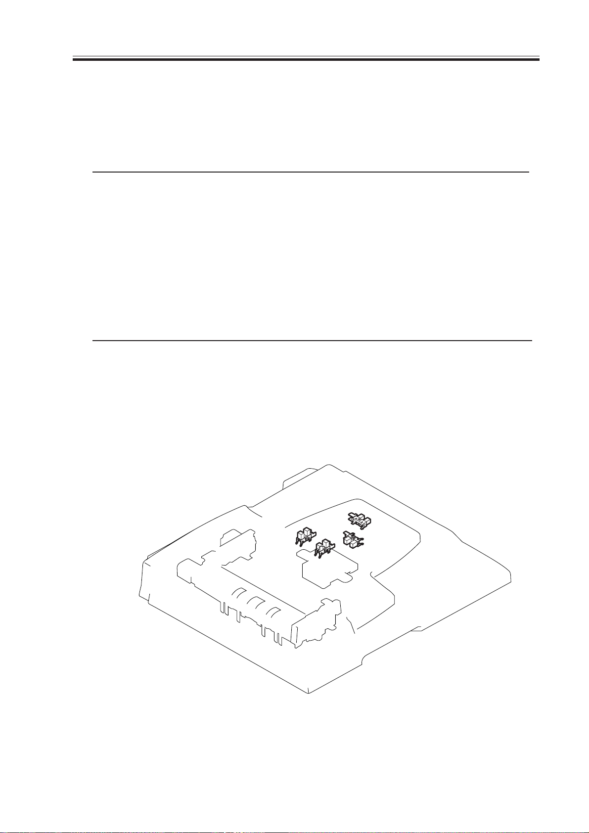
3.2 Motors, Clutches, Solenoids, PCBs, and Others
M1
CL1
PCB1
PCB2
SL1
F05-302-01
Symbol Name Notation Description
Motor M1 Feed motor
M
5-16
SL
CL
Solenoid SL1 Stamp solenoid
Cultch CL1 Pickup clutch
ADF drier PCB PCB1 ADF drive
Relay PCB PCB2 Relay for sensor inside original
pickup tray
T05-302-01
COPYRIGHT
©
2001 CANON INC. 2000 2000 2000 2000 CANON ADF-J1 REV.0 SEPT. 2001
Page 87

CHAPTER 5 TROUBLESHOOTING
4 Self Diagnosis
4.1 Outline
The machine does not have a controller PCB, and depends on the controller PCB of its
host machine for diagnosis. The checks are limited to jams, and do not look for alarm or error conditions. For discussions of jams, see 3 “Jams” in Chapter 2 (p. 2-21).
COPYRIGHT
©
2001 CANON INC. 2000 2000 2000 2000 CANON ADF-J1 REV.0 SEPT. 2001
5-17
Page 88

Page 89

APPENDIX
COPYRIGHT
©
2001 CANON INC. 2001 2001 2001 2001 CANON ADF-J1 REV.0 SEPT. 2001
Page 90

Page 91

1 General Timing Charts
1.1 Flow-Scanning a Single-sided A4 Document
Start key ONOriginal set
Feed motor (M1)
Pickup clutch (CL1)
Original placement
sensor (PI6)
Registration sensor
(PI7)
Read sensor (PI8)
Pickup roller
Separation roller
Other rollers
Original separated/
moved
: motor, roller in reverse.
Note 1: The speed increases when the paper is pulled by the pull-off roller.
1st original read 2nd original read Original delivered
Note 1 Note 1
COPYRIGHT
©
2001 CANON INC. 2000 2000 2000 2000 CANON ADF-J1 REV.0 SEPT. 2001
A-1
Page 92

Page 93

APPENDIX
2 Signal Name/Designation List
Definitions of the signal names and other designations used in this chapter and in the
block diagrams are listed below.
Note: Designations in brackets denote an electrical signal, or an analog signal whose
state cannot be represented as a 0 or 1. Other designations denote a digital signal whose
state can be represented as a 0 or 1.
DFCVS Feeder Cover Open/Closed Detection signal
SET Document Set Detection signal
LENG1 Last original detection signal
LENG2 Document Length Detection signal 1
LENG3 Document Length Detection signal 2
MOTA Feed Motor Drive signal
MOTA* Feed Motor Drive signal
MOTB Feed Motor Drive signal
MOTB* Feed Motor Drive signal
READ Read Original Document signal
REG Separated Paper Detection signal
STAMP_SL Stamp Solenoid Drive signal
WID1 Original Width Detection signal 1
WID2 Original Width Detection signal 2
COPYRIGHT
©
2001 CANON INC. 2000 2000 2000 2000 CANON ADF-J1 REV.0 SEPT. 2001
A-3
Page 94

Page 95

3 General Block Diagram
Stamp solenoid
SL
SL1
Pickup clutch
CL
CL1
Original placement
sensor
PI6
Registration
sensor
PI7
Read sensor
PI8
Cover open/closed
sensor
PI9
1
2
J201
3
3
2
2
1
1
J26
3
2
1
J27
3
2
1
J28
3
2
1
J31
3
2
1
1
2
J30
J13
2
1
J7
1
1
2
2
3
3
+24V
STAMP_SL
ADF drive PCB
+24V(P)
+24V(P)
MOT A
MOT A*
MOT B
J8
1
1
+24V
2
2
CL
3
3
4
4
MOT B*
J5
1
1
+3.3VS
2
2
SGND
3
3
1
6
2
5
3
4
4
3
5
2
6
1
4
5
6
7
8
9
10
11
12
4
5
6
7
8
9
10
11
12
J11
SET
+3.3VE
SGND
REG
+3.3VE
SGND
READ
+3.3VE
SGND
DFCVS
SGND
SGND
+3.3VE
+3.3VE
+3.3VS
SGND
SGND
+5V
+5V
SGND
DFCVS
SET
REG
WID2
WID1
N.C.CLSTAMP_SL
B15 B14 B13 B12 B11 B10 B9 B8 B7 B6 B5 B4 B3 B2 B1
J1
A1 A2 A3 A4 A5 A6 A7 A8 A9 A10 A11 A12 A13 A14 A15
B15 B14 B13 B12 B11 B10 B9 B8 B7 B6 B5 B4 B3 B2 B1
A1 A2 A3 A4 A5 A6 A7 A8 A9 A10 A11 A12 A13 A14 A15
B1 B2 B3 B4 B5 B6 B7 B8 B9 B10 B11 B12 B13 B14 B15
A15 A14 A13 A12 A11 A10 A9 A8 A7 A6 A5 A4 A3 A2 A1
MBPWM
MAPWM
PHXB
PHB
PHXA
PHA
READ
N.C.
LENG3
LENG2
LENG1
SGND
+3.3VE
SGND
LENG1
LENG2
LENG3
PGND
PGND
+24V
4321
4321
4321
Host machine
WID1
WID2
+24V
J2
J12
J6
J4
J3
1
1
2
2
3
3
4
4
5
5
6
6
J102
J101
1
1
2
2
3
3
1
1
2
2
3
3
4
4
7
7
6
6
5
5
4
4
3
3
2
2
1
1
+3.3VE
SGND
LENG1
+3.3VE
SGND
LENG2
+3.3VE
SGND
LENG3
+3.3VE
SGND
WID1
3.3VE
SGND
WID2
1
1
2
2
3
3
4
4
5
5
6
6
7
7
8
8
9
9
10
10
11
11
12
12
13
13
14
14
15
15
Junction PCB
1
2
3
4
5
6
M
M1
Feed motor
Last original detection
J21
sensor
3
PI1
2
1
J22
Length sensor 1
3
PI2
2
1
J23
Length sensor 2
3
PI3
2
1
Original width
J24
sensor 1
3
2
PI4
1
Original width
J25
sensor 2
3
2
PI5
1
COPYRIGHT
©
2001 CANON INC. 2000 2000 2000 2000 CANON ADF-J1 REV.0 SEPT. 2001
A-5
Page 96

4 ADF Controller Block Diagram
ADF Controller Block Diagram (1/4) A501
B8
A15
J1
B1
J1
A14
J1
B2
J1
A13
J1
A12
J1
B4 PHXA
J1
A11 PHB
J1
B5 PHXB
J1
A10 MAPWM
J1
B6 MBPWM
J1
A8
J1
WID1
WID2A7
LENG_1
LENG_2
LENG_3
PHA
C7
C3
C4
C5
C6
R7
R9
R10
R3
R5
J1
J1
J1
J1
J1
J1
J1
J1
J1
J1
R6
R8
A5
B11
A4
B12
A3
B13
A2
B14
A1
B15
3
4
R1
R2
R4
+24V
FU2
R28
R34
D2
D1
+3.3V
+3.3V
Q4
Q5
+3.3V
+3.3V
R31
R32
R30
R33
R29
R25
R27
R26
STAMP SL
CL
SET
C14
REG
C20
J1-A9
J1-B7
J1-A6
J1-B9
PHXA
C25
R42
+5V
R41
C9
R13
1
J6J1
J6J1
3
J3
1
J6
2
J6
+5V
C23
J7
J7
J7
J8
J8
J8
J8
J5
J5
J5
J5
J5
J5
2
3
1
2
3
4
1
2
3
4
5
6
+3.3V
+3.3V
+3.3V
C11
C12
J5
J5
J5
J5
J5
J5
R37
7
+3.3V
8
PHB
R35
9
R36
READ
C21
J1-B3
MAPWM
+3.3V
R40
10
+3.3V
11
R38
12
R39
DFCVS
C22
J1-B10
R12
C17
C26
C10
R20
R21
+3.3V
Q1
C16
1
3
5
7
9
11
13
15
17
IC1
OUTA
REFA
IN_A
VSA
OUTB
SYNCB
GNDB
INB
+3.3V
SYNCA
GNDA
INA
OUT_A
RSB
VSB
REFB
IN_B
OUT_B
1
J3
2
J3
C13 C2
+5V
R18
2
4
6
8
R11
10
12
C1
R17
14
16
18
C8
+3.3V
Q2
C18 C19
PHA
C24
R24 R23
+24V
+24V
R22
FU1
C27
MBPWM
PHXB
1
J2
2
J2
3
J2
4
J2
1
J4
2
J4
3
J4
4
J4
5
J4
6
J4
A-6
COPYRIGHT
©
2001 CANON INC. 2000 2000 2000 2000 CANON ADF-J1 REV.0 SEPT. 2001
Page 97

5 Jam Code List
No. Jam Code Explanation
1 0001 Pickup fault
2 0003 Delay jam
3 0004 Stationary jam
4 0007 Sheet-to-sheet gap jam
5 0009 ADF open jam
6 000a Feeder cover open jam
7 000b Stationary jam at power-on
8 0011 No paper (forced out original)
9 0012 Jam in response to Stop key
10 0012 Initialization jam
11 0016 Others
APPENDIX
COPYRIGHT
©
2001 CANON INC. 2000 2000 2000 2000 CANON ADF-J1 REV.0 SEPT. 2001
A-7
Page 98

APPENDIX
6 Special Tools List
The table below lists the special tools, other than those included in the standard tool set,
that are required for servicing this machine.
NO.
1
2
Tool Name
Digital multimeter FY9-2002-000 A Electrical checking,
Gauge
(1.4 mm gap)
HY9-0015-000 A Platen guide L gap
Shape Rank Use/RemarksTool No.
etc.
adjustment
HY9-0015
Note: Ranks
A: Each service engineer should be equipped with one unit of this tool.
B: One unit of this tool need be maintained for each group of five or so.
C: One unit of this tool need be maintained in each workshop.
7 Solvent/Grease List
No.
12BYUKKURIN C-17
Name Use Formulation Remarks
Cleaning
Examples:
Glass,
plastic materials,
rubber,
exterior covers
Lubricant
Driving and sliding
parts
Hydrofluorocarbon
Alcohols
Surfactant
Water
Silicone oil
- Keep away from fire.
- To be adjusted in the field.
- Substitute: IPA (Isopropyl alcohol)
- PERMALB G2
- Tool No. CK-0551 (20g)
A-8
COPYRIGHT
©
2001 CANON INC. 2000 2000 2000 2000 CANON ADF-J1 REV.0 SEPT. 2001
Page 99

Prepared by
Office Imaging Products Technical Support Division
Office Imaging Products Quality Assurance Center
CANON INC.
Printed in Japan
REVISION 0 (SEPT. 2001) (25089)
5-1, Hakusan 7-chome, Toride-shi, Ibaraki 302-8501 Japan
COPYRIGHT© 2001 CANON INC. CANON ADF-J1 REV.0 SEPT. 2001 PRINTED IN JAPAN (IMPRIME AU JAPON)
Page 100

This publication is printed on
100% reprocessed paper.
PRINTED IN JAPAN (IMPRIME AU JAPON) 0901GR0.0-1
 Loading...