

Canon imageRUNNER 2545 Series, imageRUNNER 2535 Series, imageRUNNER 2525, imageRUNNER 2530, imageRUNNER 2520 Service Manual Digest
7
6
5
4
3
2
1
imageRUNNER 2545/2535 Series
Service Manual Digest

Contents
Safety Precautions
CDRH Act -----------------------------------------------------------------------0-2
Laser Safety --------------------------------------------------------------------0-2
Handling of Laser System --------------------------------------------------0-2
Turn power switch ON -------------------------------------------------------0-3
Power Supply ------------------------------------------------------------------0-3
Safety of Toner -----------------------------------------------------------------0-4
About Toner ------------------------------------------------------------------------- 0-4
Toner on Clothing or Skin -------------------------------------------------------- 0-4
Notes When Handling the Lithium and Ni-MH Batteries ------------0-4
Notes Before it Works Serving ---------------------------------------------0-4
1 Periodical Service
Consumable Parts and Cleaning Parts ----------------------------------1-2
Cleaning Parts -----------------------------------------------------------------1-4
2 Adjustment
Outline ---------------------------------------------------------------------------2-2
Adjustment when replacing parts ---------------------------------------------- 2-2
Image position adjustment ------------------------------------------------------- 2-2
Adjustment when replacing parts -----------------------------------------2-3
Scanning System ------------------------------------------------------------------ 2-3
Action to Take after Replacing the CCD Unit ---------------------------------------- 2-3
Action to Take after Replacing the Platen Glass ------------------------------------ 2-4
Action to Take after Replacing the ADF Scan Glass ------------------------------- 2-4
Controller System ------------------------------------------------------------------ 2-5
Action to Take after Replacing theMain Controller PCB -------------------------- 2-5
Action to Take when Replacing the DC Controller PCB -------------------------- 2-5
Action to Take after Replacing the RAM ---------------------------------------------- 2-5
Laser Exposure System ---------------------------------------------------------- 2-5
Action to Take after Replacing the Laser Scanner Unit --------------------------- 2-5
Image position adjustment --------------------------------------------------2-6
Margin Along the Leading Edge ------------------------------------------------ 2-6
Left Image Margin ----------------------------------------------------------------- 2-6
Leading Edge Non-Image Width ----------------------------------------------- 2-6
Left Non-Image Width ------------------------------------------------------------ 2-7
3 Error Code
Overview ------------------------------------------------------------------------3-2
Outline -------------------------------------------------------------------------------- 3-2
Error Code ----------------------------------------------------------------------3-2
Error Code Details ----------------------------------------------------------------- 3-2
FAX Error Code -------------------------------------------------------------------- 3-9
Outline ----------------------------------------------------------------------------------------- 3-9
User Error Code ---------------------------------------------------------------------------- 3-9
Service Error Code ------------------------------------------------------------------------- 3-9
Jam Code --------------------------------------------------------------------- 3-11
Main Unit ---------------------------------------------------------------------------- 3-11
DADF-AA1 -------------------------------------------------------------------------- 3-12
Inner Finisher-B1 ------------------------------------------------------------------3-13
Alarm Code ------------------------------------------------------------------- 3-14
Alarm Code Details --------------------------------------------------------------- 3-14
4 Service Mode
Outline ---------------------------------------------------------------------------4-2
Outline of Service Mode ---------------------------------------------------------- 4-2
Using the Mode --------------------------------------------------------------------- 4-3
Setting of Bit Switch --------------------------------------------------------------- 4-3
Outline ----------------------------------------------------------------------------------------- 4-3
Details of Service Mode -----------------------------------------------------4-4
#SSSW ------------------------------------------------------------------------------- 4-4
SSSW Composition ------------------------------------------------------------------------ 4-4
Details ----------------------------------------------------------------------------------------- 4-4
#MENU ------------------------------------------------------------------------------4-12
Menu Switch Composition ---------------------------------------------------------------4-12
Deatails ---------------------------------------------------------------------------------------4-12
#NUMERIC -------------------------------------------------------------------------4-13

Numerical Parameter Composition----------------------------------------------------4-13
Details ----------------------------------------------------------------------------------------4-14
#SCAN -------------------------------------------------------------------------------4-18
Setting of Scanner Functions (SCANNER) -----------------------------------------4-18
Numeric Parameter Functional conguration ---------------------------------------4-21
READER -------------------------------------------------------------------------------------4-22
#PRINT ------------------------------------------------------------------------------4-30
Numerin Parameter Settings (Numeric Prama.) -----------------------------------4-30
Service Soft Switch Settings (PRINTER) -------------------------------------------- 4-31
List of Functions ----------------------------------------------------------------------------4-32
List of Functions(PRINT CST) ----------------------------------------------------------4-36
#NETWORK ------------------------------------------------------------------------4-37
Conrmation of contents of CA certicate ------------------------------------------- 4-37
#CODEC ----------------------------------------------------------------------------4-37
Conguration --------------------------------------------------------------------------------4-37
Details ----------------------------------------------------------------------------------------4-37
#SYSTEM ---------------------------------------------------------------------------4-38
Conguration --------------------------------------------------------------------------------4-38
Details of Bit Switch -----------------------------------------------------------------------4-38
Details of System Numeric --------------------------------------------------------------4-38
#ACC ---------------------------------------------------------------------------------4-39
Conguration --------------------------------------------------------------------------------4-39
#COUNTER ------------------------------------------------------------------------4-39
Counters -------------------------------------------------------------------------------------4-39
Clearing Counters -------------------------------------------------------------------------4-40
#LMS --------------------------------------------------------------------------------- 4-40
Conguration --------------------------------------------------------------------------------4-40
Outline ----------------------------------------------------------------------------------------4-41
Details ----------------------------------------------------------------------------------------4-41
Method of conrming license option --------------------------------------------------4-41
Inactivity of the transmitted license----------------------------------------------------4-42
Erasing a License--------------------------------------------------------------------------4-43
#E-RDS ------------------------------------------------------------------------------4-44
Conguration --------------------------------------------------------------------------------4-44
#REPORT ---------------------------------------------------------------------------4-44
Conguration --------------------------------------------------------------------------------4-44
Details ----------------------------------------------------------------------------------------4-45
#DOWNLOAD ---------------------------------------------------------------------4-49
Download ------------------------------------------------------------------------------------ 4-49
#CLEAR -----------------------------------------------------------------------------4-49
Conguration --------------------------------------------------------------------------------4-49
#DISPLAY --------------------------------------------------------------------------- 4-50
Conguration --------------------------------------------------------------------------------4-50
#ROM --------------------------------------------------------------------------------4-50
Conguration --------------------------------------------------------------------------------4-50
#TEST MODE ---------------------------------------------------------------------4-50
Outline ----------------------------------------------------------------------------------------4-50
Conguration --------------------------------------------------------------------------------4-51
Details ----------------------------------------------------------------------------------------4-51
5 Parts Replacement and Cleaning
List of Parts ---------------------------------------------------------------------5-2
List of Covers ----------------------------------------------------------------------- 5-2
List of Main Units / Parts --------------------------------------------------------- 5-4
List of PCBs ------------------------------------------------------------------------- 5-5
List of Solenoids -------------------------------------------------------------------- 5-6
List of Sensors ---------------------------------------------------------------------- 5-7
List of Motors ------------------------------------------------------------------------ 5-9
List of Fans -------------------------------------------------------------------------5-10
List of Switches -------------------------------------------------------------------- 5-11
List of Clutches -------------------------------------------------------------------- 5-12
Other ---------------------------------------------------------------------------------5-13
6 Product Overview
Specications ------------------------------------------------------------------6-2
Specications ----------------------------------------------------------------------- 6-2
Weight / Size ------------------------------------------------------------------------ 6-3
Productivity (Print speed) -------------------------------------------------------- 6-3
Paper type --------------------------------------------------------------------------- 6-4
Pickup ----------------------------------------------------------------------------------------- 6-4
Product Lineup -----------------------------------------------------------------6-4
Host machine ----------------------------------------------------------------------- 6-4
Host machine conguration -------------------------------------------------------------- 6-5
Model type ------------------------------------------------------------------------------------ 6-5

Option --------------------------------------------------------------------------------- 6-5
Pickup delivery / image reading options ---------------------------------------------- 6-5
Function expanding option --------------------------------------------------------------- 6-6
Basic Conguration -----------------------------------------------------------6-7
Functional Conguration --------------------------------------------------------- 6-7
Basic sequence ----------------------------------------------------------------------------- 6-8
7 Version Upgrading
Upgrading Targets and Procedure ----------------------------------------7-2
Outline -------------------------------------------------------------------------------- 7-2
Procedure ---------------------------------------------------------------------------- 7-3
CDRH Act
Laser Safety
Handling of Laser System
Turn power switch ON
Points to Note About
Turning Off the Main
Power Switch
Safety of Toner
Notes When Handling a
Lithium Battery
Notes Before it Works
Serving
■
■
■
■
■
■
■
■
Safety Precautions
imageRUNNER 2545/2535
Series
0
0-2
CDRH Act
The Center for Devices and Radiological Health of the US Food and Drum Administration put
into force regulations concerning laser products on August 2, 1976. These regulations apply
to laser products manufactured on and after August 1, 1976, and the sale of laser products
not certied under the regulations is banned within the Untied States. The label shown here
indicates compliance with the CDRH regulations, and its attachment is required on all laser
products that are soled in the United States.
CANON INC.
MANUFACTURED:
30-2,SHIMOMARUKO,3-CHOME,OHTA-KU,TOKYO,JAPAN
THIS PRODUCT CONHORMS WITH DHHS RADIATION
PERFORMANCE STANDARD 21CFR CHAPTER 1
SUBCHAPTER J.
A different description may be used for a different product.
Laser Safety
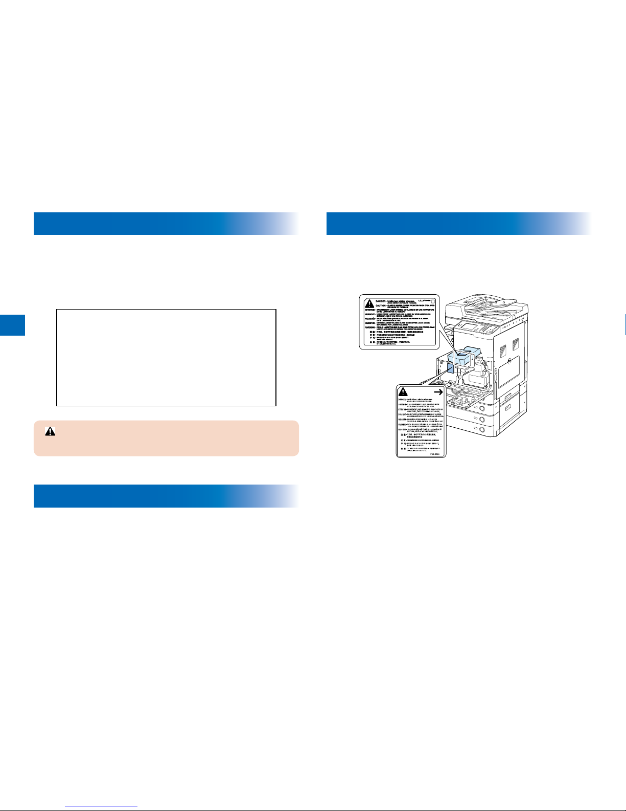
When servicing the area around the laser assembly, be sure to turn off the main power.
The machine's covers that can reect laser light are identied by means of a warning label
(Figure). If you must detach a cover showing the label, be sure to take extra caution during
the work.
F-0-1F-0-1
Handling of Laser System
When servicing the area around the laser assembly, be sure to turn off the main power.
The machine's covers that can reect laser light are identied by means of a warning label
(Figure). If you must detach a cover showing the label, be sure to take extra caution during
the work.
F-0-2F-0-2
0-3
0
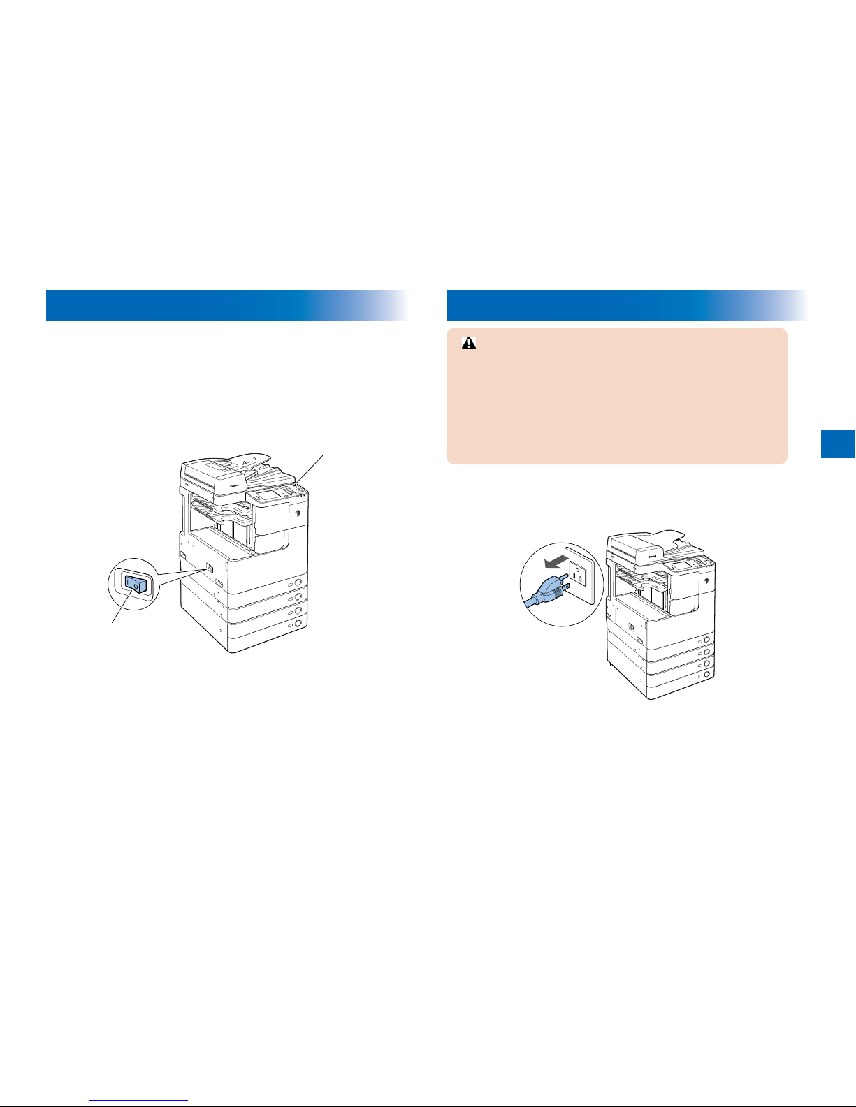
Turn power switch ON
The machine is equipped with 2 power switches: main power switch and control panel power
switch.
The machine goes on when the main power switch is turned on (i.e., other than in low power
mode, sleep mode).
Main power switch
Control panel
power switch
F-0-3F-0-3
Power Supply
1. As a general rule, do not use extension cords. Using an extension cord may
result in a re or electrical shock. If an extension cord must be used, however,
use one for local rated voltage and over, untie the cord binding, and insert
the power plug completely into the extension cord outlet to ensure a rm
connection between the power cord and the extension cord.
2. The socket-outlet shall be installed near the equipment and shall be easily
accessible.
F-0-4F-0-4

0
0-4
Safety of Toner
About Toner
The machine's toner is a non-toxic material made of plastic, iron, and small amounts of dye.
Do not throw toner into re. It may cause explosion.
Toner on Clothing or Skin
If your clothing or skin has come into contact with toner, wipe it off with tissue; then, wash it
off with water.
Do not use warm water, which will cause the toner to jell and fuse permanently with the
bers of the cloth.
Tonner is easy to react with plastic material, avoid contact with plastic.
Notes When Handling the Lithium and Ni-MH
Batteries
RISK OF EXPLOSION IF BATTERY IS REPLACED BY AN INCORRECT TYPE.
DISPOSE OF USED BATTERIES ACCORDING TO THE INSTRUCTIONS.
The following warnings are given to comply with Safety Principles (EN60950).
Wenn mit dem falschen Typ ausgewechselt, besteht Explosionsgefahr.
Gebrauchte Batterien gemäß der Anleitung beseitigen.
•
•
•
Notes Before it Works Serving
At servicing, be sure to turn OFF the power source according to the specied steps and
disconnect the power plug.

1
1
Periodical Service
Consumable Parts and Cleaning Parts
■
1
1-2
Consumable Parts and Cleaning Parts
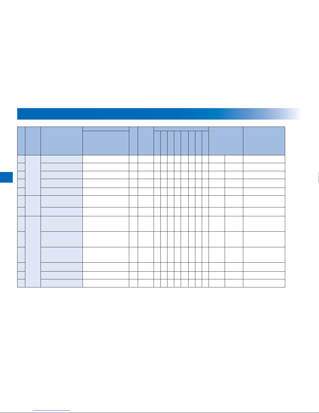
: Replaced (consumables) : Cleaned
No. System Items Parts No. Q'ty Life Interval
Counter
Remarks
iR2545/2535
7,000 sheets
40,000 sheets
80,000 sheets
120,000 sheets
142,000 sheets
150,000 sheets
240,000 sheets
500,000 sheets
1 Image
formation
system
Waste toner container
FM3-9276 1 80,000
sheets
DRBL-1 WST-TNR Dened by 6% document
2 Transfer guide
- 1 120,000
sheets
DRBL-1 DVG-CYL Wipe with dry cloth.
3 Transfer roller
FC9-0693 1 150,000
sheets
DRBL-1 TR-ROLL
4 Separation static charge
eliminator
FM3-9296 1 150,000
sheets
DRBL-1 SP-SC-EL
5 Developing unit
FM3-9263 1 500,000
sheets
DRBL-1 DVG-CYL
6 Fixing
system
Fixing inlet guide
- 1 120,000
sheets
DRBL-1 FX-UNIT Wipe with dry cloth. If dirt
cannot come off, wipe it with
alcohol.
7 Fixing unit
(For iR2545/2535)
FM4-3363 (120V)
FM3-9302 (230V)
1 240,000
sheets
DRBL-1 FX-UNIT
8 Pickup
feed
system
Cassette pickup roller
FB6-3405
FC7-9381 (For CHN)
*1 120,000
sheets
DRBL-1 C1-PU-RL,
C2-PU-RL,
C3-PU-RL,
C4-PU-RL
*: Quantity indicates number
of cassette.
9 Cassette transfer roller
FC6-7083
FC7-9502 (For CHN)
*1 120,000
sheets
DRBL-1 - Replace with cassette
separation pad.
*: Quantity indicates number
of cassette.
10 Cassette separation roller
FC6-6661 *1 120,000
sheets
DRBL-1 C1-SP-RL,
C2-SP-RL,
C3-SP-RL,
C4-SP-RL
*: Quantity indicates number
of cassette.
11 Cassette idler gear
(Only for China)
FU3-0280 *1 120,000
sheets
DRBL-1 - *: Quantity indicates number
of cassette.
12 Manual feed pickup roller
FL3-1352 1 150,000
sheets
DRBL-1 M-PU-RL
13 Manual feed separation pad
FL3-3469 1 150,000
sheets
DRBL-1 M-SP-PD
1-3
1
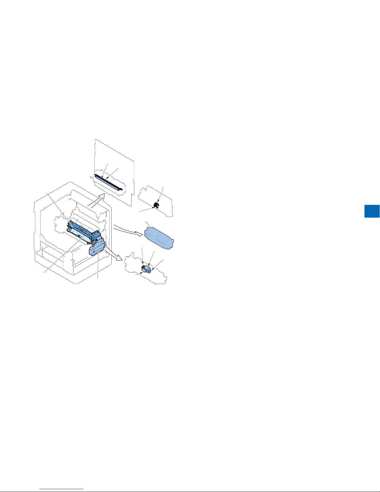
[4]
[8]
[3]
[9]
[1]
[6]
[2]
[7]
[10]
[11]
[5]
[12]
[1] Transfer roller
[2] Separation static eliminator
[3] Waste toner container
[4] Drum unit
[5] Developing assembly
[6] Manual feed pickup roller
[7] Manual feed separation pad
[8] Fixing unit
[9] Cassette pickup roller
[10] Cassette transfer roller
[11] Cassette separation roller
[12] Idler gear (for China)
F-1-1F-1-1

1
1-4
Cleaning Parts
Fixing
guide
Transfer
guide
F-1-2F-1-2

2
2
Adjustment
Outline
Adjustment when replacing parts
Image position adjustment
■
■
■
2
2-2
Outline
Adjustment when replacing parts
This section describes adjustment required in eld service works when replacing parts.
The parts are classied by function into the following 3 blocks.
Category
Replacing parts Reference
Scanning
System
CCD unit
"Action to Take after Replacing the CCD Unit"(page 2-3).
Copyboard glass "Action to Take after Replacing the Platen Glass"(page 2-4).
ADF reading glass
"Action to Take after Replacing the ADF Scan Glass"(page
2-4).
Controller
System
Main controller PCB "Action to Take after Replacing theMain Controller
PCB"(page 2-5).
DC controller PCB "Action to Take when Replacing the DC Controller
PCB"(page 2-5).
RAM PCB "Action to Take after Replacing the RAM"(page 2-5).
Laser Exposure
System
Laser scanner unit "Action to Take after Replacing the Laser Scanner
Unit"(page 2-5).
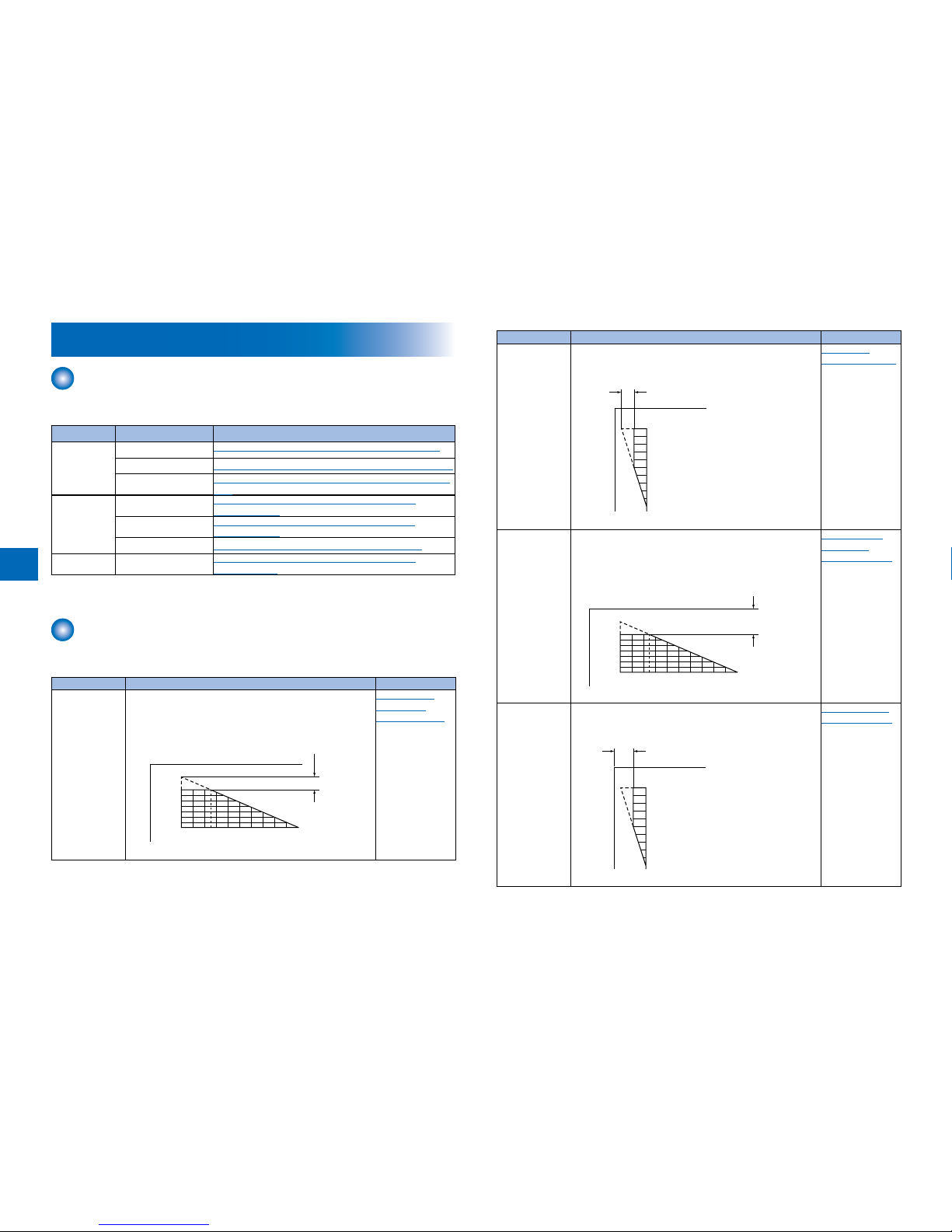
Image position adjustment
This section describes procedures when adjusting basic image position (image margins,
nonimage area, etc).
Category Item Reference
Margin Along the
Leading Edge
Single-sided copy: 2.5 ± 1.5 (mm)
Double-sided copy: 2.5 ± 2.0 (mm)
2 54 6 8 10 12 14 16 18 200
2.5+/-1.5mm
(2nd side of double-sided copy
: 2.5+/-2.0mm)
"Margin Along
the Leading
Edge"(page 2-6).
T-2-1T-2-1
Category Item Reference
Left Image MarginSingle-sided copy: 2.5 ± 1.5 (mm)
Double-sided copy: 2.5 ± 2.0 (mm)
10
8
6
5
4
2
0
2.5+/-1.5mm
(2nd side of double-sided copy:
2.5+/-2.0mm)
"Left Image
Margin"(page 2-6).
Leading Edge
Non-Image Width
Single-sided copy: 2.5 ± 1.5 (mm)
Double-sided copy: 2.5 ± 1.5 (mm)
2 54 6 8 10 12 14 16 18 200
2.5+/-1.5mm
(2nd side of double-sided copy:
2.5+/-1.5mm)
"Leading Edge
Non-Image
Width"(page 2-6).
Left Non-Image
Width
Single-sided copy: 2.5 ± 1.5 (mm)
Double-sided copy: 2.5 ± 1.5 (mm)
10
8
6
5
4
2
0
2.5+/-1.5mm
(2nd side of double-sided copy:
2.5+/-1.5mm)
"Left Non-Image
Width"(page 2-7).
T-2-2T-2-2
2-3
2
Adjustment when replacing parts
Scanning System
Action to Take after Replacing the CCD Unit
Perform the following procedure after replacing the CCD unit:
1) Install the new CCD unit.
2) Turn on the power to cause the error “E248”.
3) Enter the service mode and perform the following:
SCAN > READER > FUNCTION > CLEAR > R-CON (RCON RAM clearing)
4) Turn OFF and then ON the main power switch.
5) Enter the following items according to the service data list output in advance.
SCAN> READER> ADJUST> ADJ-XY> ADJ-X
ADJ-Y
ADJ-S
ADJ-Y-DF
ADJ-X-MG
SCAN> READER> ADJUST> PASCAL> OFST-P-K
SCAN> READER> ADJUST> CCD> 50_RG
50_GB
100_RG
100_GB
50DF_RG
50DF_GB
100DF_RG
100DF_GB
W-PLT-X
W-PLT-Y
W-PLT-Z
SCAN> FEEDER> ADJUST> DOCST
LA-SPEED
SCAN> READER> OPTION> BODY> SENS-CNF
MODELSZ2
KSIZE-SW
6) Perform the following in the service mode:
SCAN> READER> FUNCTION> CCD> DF-WLVL1/2/3/4 (DF white level adjustment)
6-1) Place a sheet of paper that the user usually uses on the platen glass, enter the
service mode, and then select SCAN > READER > FUNCTION > CCD > DFWLVL1.
Read the white level in the BOOK mode. (Check the transparency of the glass for
BOOK mode.)
6-2) Place a sheet of paper that the user usually uses on the DF, enter the service mode,
and then select SCAN > READER > FUNCTION > CCD > DF-WLVL2.
Read the white level in the DF mode (stream reading). (Check the transparency of the
■
T-2-3T-2-3
glass for stream reading.)(Read both sides of the chart.)
6-3) Place a sheet of paper that the user usually uses on the platen glass, enter the
service mode, and then select SCAN > READER > FUNCTION > CCD > DFWLVL3.
Read the white level in the BOOK mode. (Check the transparency of the glass for
BOOK mode.)
6-4) Place a sheet of paper that the user usually uses on the DF, enter the service mode,
and then select SCAN > READER > FUNCTION > CCD > DF-WLVL4.
Read the white level in the DF mode (stream reading). (Check the transparency of the
glass for stream reading.)(Read both sides of the chart.)
7) Enter the service mode, and then select the following:
SCAN > READER > FUNCTION > INSTALL > STRD-POS CCD (stream reading position
adjustment).
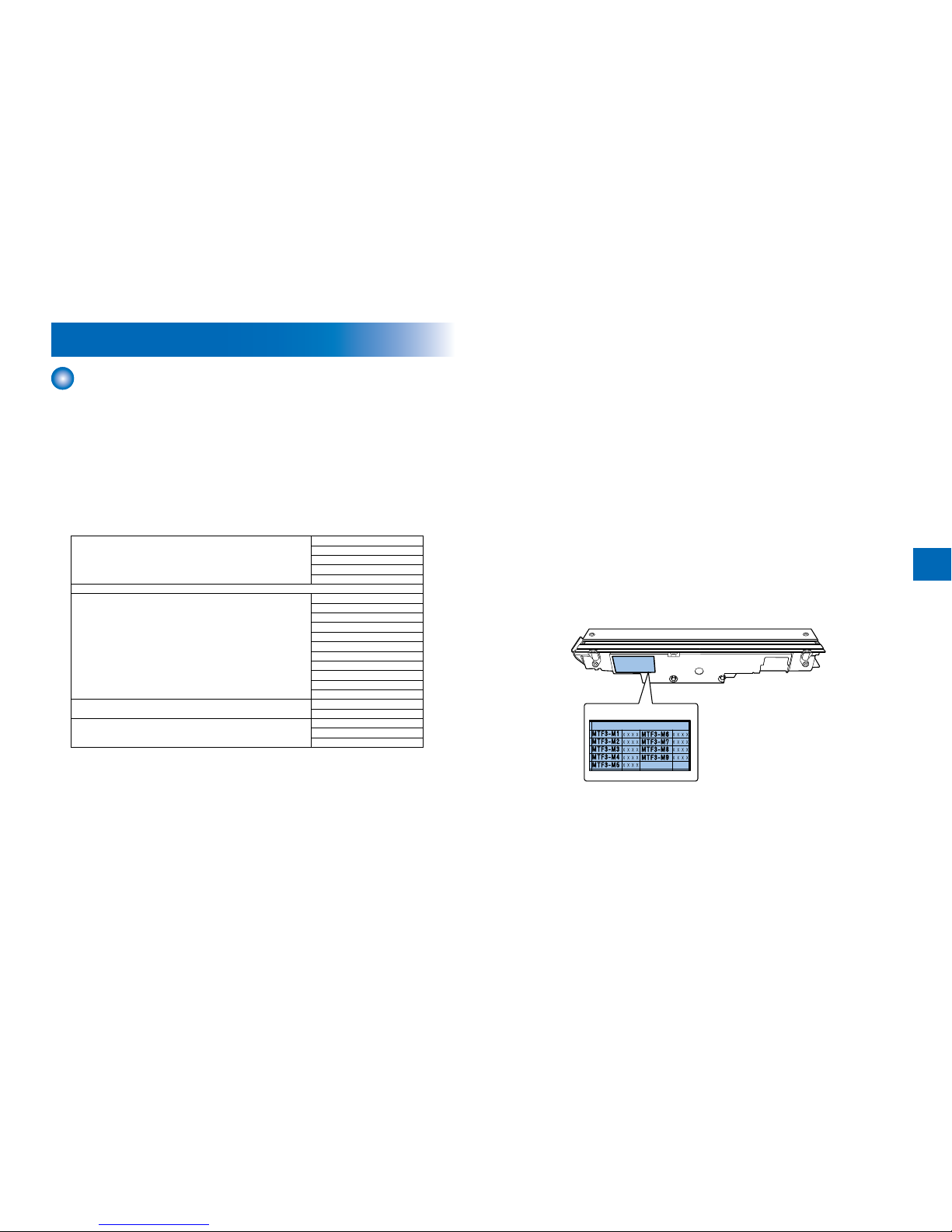
8) Enter the values recorded on the label afxed to the CCD unit in the following service
mode. (Two items below)
SCAN > READER > ADJUST > CCD > MTF3-M1/M2/M3/M4/M5/M6/M7/M8/M9
Next, nalize the setting in the following mode:
SCAN > READER > ADJUST > CCD > CCD-CHNG
SCAN> READER> ADJUST> CCD>
9) Transcribe the above correction values on the service label at the inside of the rear cover
(right).
F-2-1F-2-1

2
2-4
Action to Take after Replacing the Platen Glass
CAUTION:
Be sure to make the white plate data adjustment before ADF white level
adjustment.
W-PLT-X
W-PLT-Y
W-PLT-Z
F-2-2F-2-2
1.Enter the value indicated on the platen glass in the following service mode:
SCAN > READER > ADJUST > CCD > W-PLT-X/Y/Z (Input of standard white plate data)
2.Enter the service mode, and then select the following:
SCAN > READER > FUNCTION > CCD > DF-WLVL1/2/3/4 (DF white level adjustment)
1) Place a sheet of paper that the user usually uses on the platen glass, enter the
service mode, and then select SCAN > READER > FUNCTION > CCD > DFWLVL1.
Read the white level in the BOOK mode. (Check the transparency of the glass for
BOOK mode.)
2) Place a sheet of paper that the user usually uses on the DF, enter the service mode,
and then select SCAN > READER > FUNCTION > CCD > DF-WLVL2.
Read the white level in the DF mode (stream reading). (Check the transparency of the
glass for stream reading.)(Read both sides of the chart.)
3) Place a sheet of paper that the user usually uses on the platen glass, enter the
service mode, and then select SCAN > READER > FUNCTION > CCD > DFWLVL3.
Read the white level in the BOOK mode. (Check the transparency of the glass for
BOOK mode.)
4) Place a sheet of paper that the user usually uses on the DF, enter the service mode,
and then select SCAN > READER > FUNCTION > CCD > DF-WLVL4.
Read the white level in the DF mode (stream reading). (Check the transparency of the
glass for stream reading.)(Read both sides of the chart.)
■
Action to Take after Replacing the ADF Scan Glass
1.Enter the service mode, and then select the following:
SCAN > READER > FUNCTION > CCD > DF-WLVL1/2/3/4 (DF white level adjustment)
1) Place a sheet of paper that the user usually uses on the platen glass, enter the
service mode, and then select SCAN > READER > FUNCTION > CCD > DFWLVL1.
Read the white level in the BOOK mode. (Check the transparency of the glass for
BOOK mode.)
2) Place a sheet of paper that the user usually uses on the DF, enter the service mode,
and then select SCAN > READER > FUNCTION > CCD > DF-WLVL2.
Read the white level in the DF mode (stream reading). (Check the transparency of the
glass for stream reading.)(Read both sides of the chart.)
3) Place a sheet of paper that the user usually uses on the platen glass, enter the
service mode, and then select SCAN > READER > FUNCTION > CCD > DFWLVL3.
Read the white level in the BOOK mode. (Check the transparency of the glass for
BOOK mode.)
4) Place a sheet of paper that the user usually uses on the DF, enter the service mode,
and then select SCAN > READER > FUNCTION > CCD > DF-WLVL4.
Read the white level in the DF mode (stream reading). (Check the transparency of the
glass for stream reading.)(Read both sides of the chart.)
■
2-5
2
Controller System
Action to Take after Replacing theMain Controller PCB
After replacing the main controller PCB with a new one, take the following action:
Download the latest rmware with the UST.
Enter all values recorded on the service label afxed to the rear cover.
Action to Take when Replacing the DC Controller PCB
Before Replacement/RAM Clearing
Print the service data list in the service mode.
REPORT > REPORT OUTPUT > SERVICE DATA LIST
Action to Take after Replacement/RAM Clearing
1) Clear the DC controller settings and counters.
Enter the service mode, and Then select the following:
CLEAR > ENGINE > ENGINE BKRAMCLK (Clearing of the RAM on the DC controller
PCB)
2) Turn OFF and then ON the main power switch. (Turning OFF/ON the main power switch
clears the RAM.)
3) If uploading of backup data fails before replacement due to the damage to the DC
controller PCB, enter the values of service mode items recorded on the service label.
Since the values recorded on the service label may be outdated, check the service mode
item list (#SERVICE DATA LIST) printed out in advance, and then enter the latest values.
4) Turn OFF and then ON the main power switch. (Turning OFF/ON the main power switch
allows the values entered for the service mode items to take effect.)
■
•
•
■
Action to Take after Replacing the RAM
CAUTION:
The ADRAM is powered from the secondary battery unit to back up the image memory
even after the main power switch is turned OFF and the power plug is removed from
the outlet.
If the SW3 on the main controller PCB is pressed with the image backed up, the entire
data stored in the memory is cleared. Be sure to output the data stored in the memory
Laser Exposure System
Action to Take after Replacing the Laser Scanner Unit
When replacing the laser unit, enter the values recorded on the label afxed to the laser unit
to be replaced for the following in the service mode:
145 146 147 136 148 149 150
SW No.
PRINT > Bitswitch > 136 Laser horizontal scanning direction write position adjustment(A)
PRINT > Bitswitch > 145 Laser horizontal scanning direction magnication ratio
adjustment(A-B)
PRINT > Bitswitch > 146 Laser horizontal scanning direction magnication ratio
adjustment(A-C)
PRINT > Bitswitch > 147 Laser horizontal scanning direction magnication ratio
adjustment(A-D)
PRINT > Bitswitch > 148 Laser horizontal scanning direction write position adjustment(A-B)
PRINT > Bitswitch > 149 Laser horizontal scanning direction write position adjustment(A-C)
PRINT > Bitswitch > 150 Laser horizontal scanning direction write position adjustment(A-D)
■
■
•
•
•
•
•
•
•
F-2-3F-2-3
2
2-6
Image position adjustment
Copy 10 sheets from each pickup position to check that the image margin and non-image
area is within the standard.
Each cassette
Pickup tray
If it is not within the standard, go through the following procedures to adjust it.
CAUTION:
If changing the value of service mode item in this adjustment, enter the changed value
in the service label.
Margin Along the Leading Edge
Service mode> PRINT> PRINT NUMERIC> 053
2 54 6 8 10 12 14 16 18 200
Paper
leading edge
Decrease the value.
(a decrease of '10' will
increase the margin by 1 mm)
Increase the value.
(an increase of '10' will
increase the margin by 1 mm)
1st side of copy: 2.5+/-1.5mm
•
•
F-2-4F-2-4
Left Image Margin
Service mode> PRINT> PRINT NUMERIC> 056
10
8
6
5
4
2
0
1st side of copy: 2.5+/-1.5mm
Image left edge
Increase the value.
(an increase of '10' will
increase the margin
width by 1 mm)
Decrease the value.
(a decrease of '10' will
decrease the margin
width by 1 mm)
Leading Edge Non-Image Width
Service mode> SCAN> READER> ADJUST> ADJ-XY> ADJ-X
2 54 6 8 10 121416 18 200
1st side of copy: 2.5+/-1.5mm
Image leading
edge
Decrease the value.
(a decrease of '10' will decrease
the non-image width by 1 mm)
Increase the value.
(an increase of '10' will
increase the non-image
width by 1 mm)
F-2-5F-2-5
F-2-6F-2-6

2-7
2
Left Non-Image Width
Service mode> SCAN> READER> ADJUST> ADJ-XY> ADJ-Y
10
8
6
5
4
2
0
1st side of copy: 2.5+/-1.5mm
Image edge
Increase the value.
(an increase of '10' will
increase the non-image
width by 1 mm)
Decrease the value.
(a decrease of '10' will
decrease the non-image
width by 1 mm)
F-2-7F-2-7

3
3
Error Code
Over View
Error Code
Jam Code
Alarm Code
■
■
■
■
3
3-2
Overview
Outline
This chapter describes various codes which are displayed when a failure occurs on the
product. These are classied into 3 codes as follows.
Code type Explanation Reference
Error code This code is displayed when an error occurs on the machine. Refer to
page 3-2
Jam code This code is displayed when a jam occurs inside the machine. Refer to
page 3-11
Alarm code This code is displayed when a function of the machine is
malfunctioned.
Refer to
page 3-14
T-3-1T-3-1
Error Code
Error Code Details
Ecode Detail
Code
Item Description
E000 0001
Title Fixing temperature abnormal rise
Description The temperature detected by the main thermistor does not
rise to the specied value during startup control.
Remedy 1.Go through the following to clear the error: CLEAR >
ENGIN > ERRCLR; and then turn OFF and then ON the
power.
2.Check connection of the Connectors (Thermistor Connector
and AC Connector).
3.Replace the Fixing Main Thermistor (Film Unit).
4.Replace the Fixing Assembly.
5.Replace the DC Controller PCB (PCB4).
E001 0000
Title Fixing unit temperature rise detection
Description The reading of the main thermistor is 250 deg C or more
continuously for 200 msec.
Remedy 1.Go through the following to clear the error: CLEAR >
ENGIN > ERRCLR; and then turn OFF and then ON the
power.
2.Check connection of the Connectors (Thermistor Connector
and AC Connector).
3.Replace the Fixing Main Thermistor (Film Unit).
4.Replace the Fixing Assembly.
5.Replace the DC Controller PCB (PCB4).
E001 0001
Title Fixing unit temperature rise detection
Description The hardware circuit detects overheating of the main or sub
thermistor for 200 msec.
Remedy 1.Go through the following to clear the error: CLEAR >
ENGIN > ERRCLR; and then turn OFF and then ON the
power.
2.Replace the DC Controller PCB (PCB4).
E001 0002
Title Fixing unit temperature rise detection
Description The reading of the sub thermistor is 295 deg C or more
continuously for 200 msec.
Remedy 1.Go through the following to clear the error: CLEAR >
ENGIN > ERRCLR; and then turn OFF and then ON the
power.
2.Check connection of the Connectors (Thermistor Connector
and AC Connector).
3.Replace the Fixing Main Thermistor (Film Unit).
4.Replace the Fixing Assembly.
5.Replace the DC Controller PCB (PCB4).
3-3
3
Ecode Detail
Code
Item Description
E002 0000
Title Fixing unit temperature insufcient rise
Description 1.The reading of the main thermistor is less than 115 deg C
continuously for 400 msec 1.3 sec after it has indicated 100
deg C.
2.The reading of the main thermistor is less than 150 deg C
continuously for 400 msec 1.3 sec after it has indicated 140
deg C.
Remedy 1.Go through the following to clear the error: CLEAR >
ENGIN > ERRCLR; and then turn OFF and then ON the
power.
2.Check connection of the Connectors (Thermistor Connector
and AC Connector).
3.Replace the Fixing Main Thermistor (Film Unit).
4.Replace the Fixing Assembly.
5.Replace the DC Controller PCB (PCB4).
E003 0000
Title Low xing temperature detection after standby
Description The reading of the main thermistor is less than 140 deg C
continuously for 400 msec or more.
Remedy 1.Go through the following to clear the error: CLEAR >
ENGIN > ERRCLR; and then turn OFF and then ON the
power.
2.Check connection of the Connectors (Thermistor Connector
and AC Connector).
3.Replace the Fixing Main Thermistor (Film Unit).
4.Replace the Fixing Assembly.
5.Replace the DC Controller PCB (PCB4).
E004 0000
Title Thermistor disconnection detection error
Description When disconnection is detected with connector (J214) for 30
sec continuously.
Remedy 1.Check connection of the Connector (J214).
2.Replace the Film Unit.
3.Replace the Fixing Assembly.
4.Replace the DC Controller PCB (PCB4).
E010 0001
Title Unstable rotation of the Main Motor (M1)
Description Detection is executed every 100 msec after the start of motor
rotation; however, the drive detection signal is absent for 2
sec.
Remedy 1.Replace the Main Motor (M1).
2.Replace the DC Controller PCB (PCB4).
E010 0002
Title Unstable rotation of the Main Motor (M1)
Description During motor rotation, detection is executed every 100 msec;
however, the drive signal is absent 5 times in sequence.
Remedy 1.Replace the Main Motor (M1).
2.Replace the DC Controller PCB (PCB4).
Ecode Detail
Code
Item Description
E014 0001
Title Unstable rotation of the Fixing Motor (M2)
Description Detection is executed every 100 msec after the start of motor
rotation; however, the drive detection signal is absent for 2
sec.
Remedy 1.Replace the Fixing Motor (M2).
2.Replace the DC Controller PCB (PCB4).
E014 0002
Title Unstable rotation of the Fixing Motor (M2)
Description During motor rotation, detection is executed every 100 msec;
however, the drive signal is absent 5 times in sequence.
Remedy 1.Replace the Fixing Motor (M2).
2.Replace the DC Controller PCB (PCB4).
E019 0000
Title Error in Waste Toner Sensor (S17)
Description Warning when the sensor goes on for 2000 consecutive
sheets, and error when the sensor goes on for 100
consecutive sheets.
* Error occurs after the delivery if a paper in passage exists.
Remedy 1.Replace the Waste Toner Sensor (S17).
2.Replace the DC Controller PCB (PCB4).
E020 0000
Title The path between the sub hopper and the developing
assembly is clogged with toner.
Description The Developing Assembly Toner Sensor (TS1) detects the
absence of toner,while the Sub Hopper Toner Sensor (TS2)
detects the presence of toner.
With the Developing Cylinder Clutch (CL3) turned on,
the hopper feedscrew motor (M7) is rotated for 1 sec
intermittently 194 times; still, theDeveloping Assembly Toner
Sensor (TS1) does not detect the presence of toner.
* Error occurs after the delivery if a paper in passage exists.
Remedy 1.Check the rotation of hopper motor gear. (If rotating, false
detection by the sensor is doubted. Feed the toner to the
developing unit in service mode: CLEAR>ENGIN>TNRINST.)
2.Replace the Developing Assembly Toner Sensor (TS1).
3.Replace the Sub Hopper Toner Sensor (TS2).
4.Replace the DC Controller PCB (PCB4).
E024 0000
Title The connector (J207) of Developing Assembly Toner Sensor
(TS1) is disconnected.
Description The Developing Assembly Toner Sensor (TS1) connection
detection signal is absent for 100 msec 10 times in sequence.
* Error occurs after the delivery if a paper in passage exists.
Remedy 1.Check connection of the Connector (J207).
2.Replace the Developing Assembly Toner Sensor (TS1).
3.Replace the DC Controller PCB (PCB4).
3
3-4
Ecode Detail
Code
Item Description
E024 0001
Title The Developing Assembly Toner Sensor (TS1) is
disconnected.
Description <At LOW SPEED>
- The developing assembly toner sensor (TS1) ON counter
is checked every 2.5 seconds, and the counter increments
1 count every 25 times when the sensor goes on, and 300
counts are reached.
<At HIGH SPEED>
- The developing assembly toner sensor (TS1) ON counter
is checked every 1.5 seconds, and the counter increments
1 count every 15 times when the sensor goes on, and 300
counts are reached.
Remedy 1.Check connection of the Connector (J207).
2.Correct the cable.
3.Replace the Developing Assembly Toner Sensor (TS1).
E025 0000
Title The connector (J207) of Sub Hopper Toner Sensor (TS2) is
disconnected.
Description The Sub Hopper Toner Sensor (TS2) connection detection
signal is absent for 100 msec 10 times in sequence.
* Error occurs after the delivery if a paper in passage exists.
Remedy 1.Check connection of the Connector (J207).
2.Replace the Sub Hopper Toner Sensor (TS2).
3.Replace the DC Controller PCB (PCB4).
E025 0001
Title Failure of the Bottle Motor (M6)
Description The bottle motor (M6) is unlocked when it goes on for 12
consecutive times at 0.1 sec. intervals.
* Error occurs after the delivery if a paper in passage exists.
Remedy 1.Replace the Bottle Motor (M6).
2.Replace the DC Controller PCB (PCB4).
E110 0001
Title Failure of the Scanner Motor (M21)
Description The Scanner Motor (M21) speed lock signal does not indicate
a locked state a specic period of time after the Scanner
Motor (M21) has been started.
* The same condition is detected after the error retry is
performed.
Remedy 1.Check the cable.
2.Replace the Laser Scanner Unit.
3.Replace the DC Controller PCB (PCB4).
Ecode Detail
Code
Item Description
E110 0002
Title Failure of the Scanner Motor (M21)
Description The speed lock signal indicates a deviation 10 times in
sequence at intervals of 100 msec after the signal has
indicated a locked state.
* The same condition is detected after the error retry is
performed.
Remedy 1.Check the cable.
2.Replace the Laser Scanner Unit.
3.Replace the DC Controller PCB (PCB4).
E110 0003
Title Failure of the Scanner Motor (M21)
Description The scanner motor (M21) speed lock signal does not indicate
a locked state for 6.5 sec. after a switchover is made from
low to normal speed or for 8 sec. after a switchover is made
from normal to low speed.
* The same condition is detected after the error retry is
performed.
Remedy 1.Check the cable.
2.Replace the Laser Scanner Unit.
3.Replace the DC Controller PCB (PCB4).
E196 0000
Title Error in EEPROM access
Description 20 retries failed after error occurred during communication
with EEPROM.
* Error occurs after the delivery if a paper in passage exists.
Remedy 1.Replace the DC Controller PCB (PCB4).
E197 0000
Title Error in communication of Laser Driver PCB (PCB14)
Description Communication error 1 with image PCB
Remedy 1.Check the cable.
2.Replace the Laser Scanner Unit.
3.Replace the DC Controller PCB (PCB4).
E197 0001
Title Error in communication of Laser Driver PCB (PCB14)
Description Communication error 2 with image PCB
Remedy 1.Check the cable.
2.Replace the Laser Scanner Unit.
3.Replace the DC Controller PCB (PCB4).
E202 0000
Title There is an error in the detection of the CCD home position.
Description 1.The attempt to detect the home position fails when the CCD
is moved forward.
2.The attempt to detect the home position fails when the CCD
is moved back.
Remedy 1.Disconnect and then connect the exible cable(Relay PCB
(PCB2)-Main Controller PCB (PCB1) 64pin).
2.Replace the exible cable.
3.Replace the CCD HP sensor (S22).
4.Replace the Scanner Motor (M21).
5.Replace the Relay PCB (PCB2).
6.Replace the Main Controller PCB (PCB1).
3-5
3
Ecode Detail
Code
Item Description
E225 0000
Title The light intensity of the CCD is faulty.
Description The light intensity of the CCD during shading is under the
specied level.
Remedy "1.Disconnect and then connect the exible cable.
2.Replace the exible cable.
3.Replace the CCD Unit.
4.Replace the Relay PCB (PCB2).
5.Replace the Main Controller PCB (PCB1)."
E227 0000
Title The reader unit power supply (24V) is faulty.
Description 1.At time of power-on, the 24V port is off.
2.At the start of a job, the 24V port is off.
3.At the end of a job, the 24V port is off.
4.When a load is being driven, the 24V port is off.
Remedy 1.Disconnect and then connect the power supply harness
connector.
2.Replace the Power Supply PCB (PCB3).
E240 0000
Title Error in controller communication
Description The serial communication error such as parity error or
overrun error is constantly detected.
Remedy 1.Check the Connectors.
2.Replace the DC Controller PCB (PCB4).
E240 0001
Title Error in controller communication
Description The serial communication error such as parity error or
overrun error is detected while printing.
Remedy 1.Check the Connectors.
2.Replace the DC Controller PCB (PCB4).
E246 0000
Title Writing to the counter PCB (FRAM) failed
Description Remedy -
E247 0000
Title Mismatched checksum between the Flash Rom and the
FRAM
Description Remedy -
Ecode Detail
Code
Item Description
E248 0000
Title EEPROM error
Description 1.An error has occurred at power-on.
2.An error has occurred during write operation.
3.An error has occurred during read operation following write
operation.
Remedy 1.Disconnect and then connect the exible cable(Relay PCB
(PCB2)-Main Controller PCB (PCB1) 50pin).
2.Disconnect and then connect the exible cable(CCD unit-
Relay PCB (PCB2)).
3.Disconnect and then connect the power supply harness
connector.
4.Replace the exible cable.
5.Replace the CCD Unit.
6.Replace the Relay PCB (PCB2).
7.Replace the Power Supply PCB (PCB3).
8.Replace the Main Controller PCB (PCB1).
E261 0000
Title Error in Zero Cross
Description Zero Cross failed to be detected for 500ms or more while the
relay was ON.
* The same condition is detected after the error retry is
performed.
Remedy 1.Check the Connectors.
2.Replace the DC Controller PCB (PCB4).
E280 0000
Title Reading unit communication error
Description Reading error after writing.
Remedy 1.Disconnect and then connect the exible cable(Relay PCB
(PCB2)-Main Controller PCB (PCB1) 50pin).
2.Disconnect and then connect the exible cable(Relay PCB
(PCB2)-Main Controller PCB (PCB1) 64pin).
3.Disconnect and then connect the exible cable(CCD unit-
Relay PCB (PCB2)).
4.Replace the exible cable.
5.Replace the Relay PCB (PCB2).
6.Replace the Main Controller PCB (PCB1).
E350 0000
Title SOFT-ID PCB error
Description Remedy -
E354 0000
Title Mismatched serial number for the SOFT-ID PCB
Description Remedy -
E355 0000
Title Mismatched serial number between the SOFT-ID, the Flash
Rom and the FRAM
Description Remedy -
3
3-6
Ecode Detail
Code
Item Description
E355 0004
Title System information error
Description Remedy -
E355 0005
Title System information error
Description Remedy -
E413 0000
Title Release Motor (M2) error
Description The sensing level of the release motor HP sensor (SR11)
does not change within a specied period when the release
motor (M2) is driven.
Remedy 1.Replace the Release Motor HP Sensor (SR11).
2.Replace the Release Motor (M2).
3.Replace the ADF Driver PCB.
E500 0000
Title Communication error
Description The communication with the host machine is interrupted.
Remedy 1.Check the cable.
2.Replace the Finisher Controller PCB (PCB1).
3.Replace the DC Controller PCB.
E505 0001
Title EEPROM error
Description The checksum for the EEPROM data has an error.
Remedy 1.Replace the Finisher Controller PCB (PCB1).
E520 0001
Title Shift Motor (M4) error
Description The shift roller does not leave the shift roller home position
when the Shift Motor (M4) has been driven for 1.2 seconds.
Remedy 1.Replace the Shift Roller HP Sensor (S2).
2.Replace the Shift Motor (M4).
3.Replace the Finisher Controller PCB (PCB1).
E520 0002
Title Shift Motor (M4) error
Description The shift roller does not return to the shift roller home position
when the Shift Motor (M4) has been driven for 1.2 seconds.
Remedy 1.Replace the Shift Roller HP Sensor (S2).
2.Replace the Shift Motor (M4).
3.Replace the Finisher Controller PCB (PCB1).
E531 8001
Title Stapler Motor (M10) error
Description The stapler does not leave the staple home position when the
Staple Motor (M10) has been driven for 0.5 sec.
Remedy 1.Check the wiring between the Finisher Controller PCB and
Stapler.
2.Replace the Stapler.
3.Replace the Finisher Controller PCB (PCB1).
Ecode Detail
Code
Item Description
E531 8002
Title Stapler Motor (M10) error
Description The stapler does not return to the staple home position when
the Stapler Motor (M10) has been driven for 0.5 sec.
Remedy 1.Check the wiring between the Finisher Controller PCB and
Stapler.
2.Replace the Stapler.
3.Replace the Finisher Controller PCB (PCB1).
E532 0001
Title STP Move Motor (M1) error
Description The stapler does not leave the stapler move home position
when the STP Move Motor (M1) has been driven for 0.25 sec.
Remedy 1.Replace the Stapler Move HP Sensor (S10).
2.Check the wiring between the Finisher Controller PCB and
the STP Move Motor.
3.Check the stapler shift base.
4.Replace the STP Move Motor (M1).
5.Replace the Finisher Controller PCB (PCB1).
E532 0002
Title STP Move Motor (M1) error
Description The stapler does not return to the stapler move home position
when the STP Move Motor (M1) has been driven for 2.8 sec.
Remedy 1.Replace the Stapler Move HP Sensor (S10).
2.Check the wiring between the Finisher Controller PCB and
the STP Move Motor.
3.Check the stapler shift base.
4.Replace the STP Move Motor (M1).
5.Replace the Finisher Controller PCB (PCB1).
E540 0001
Title Tray Lift Motor (M11) time out error
Description The stack tray does not move within a specied time period.
Remedy 1.Replace the Tray Lift Motor (M11).
2.Replace the Finisher Controller PCB (PCB1).
E540 0005
Title Tray Lift Motor (M11) closing detect switch error
Description The FG input cannot be detected when the Tray Lift Motor
(M11) has been driven for 0.1 second.
Remedy 1.Replace the Stack Tray Clock Sensor (S13).
2.Replace the Tray Lift Motor (M11).
3.Replace the Finisher Controller PCB (PCB1).
E542 0001
Title Additional Tray Lift Motor (M12) time out error
Description The stack tray does not move within a specied time period.
Remedy 1.Replace the Additional Tray Lift Motor (M12).
2.Replace the Finisher Controller PCB (PCB1).
E542 0005
Title Additional Tray Lift Motor (M12) closing detect switch error
Description The FG input cannot be detected when the Additional Tray
Lift Motor (M12) has been driven for 0.1 second.
Remedy 1.Replace the Additional Tray Clock Sensor (S23).
2.Replace the Additional Tray Lift Motor (M12).
3.Replace the Finisher Controller PCB (PCB1).
3-7
3
Ecode Detail
Code
Item Description
E567 0001
Title Shift Roller Release Motor (M5) error
Description The shift roller does not leave the shift roller release home
position when the Shift Roller Release Motor (M5) has been
driven for 0.1 sec.
Remedy 1.Replace the Shift Roller Release Sensor (S3).
2.Replace the Shift Roller Release Motor (M5).
3.Replace the Finisher Controller PCB (PCB1).
E567 0002
Title Shift Roller Release Motor (M5) error
Description The shift roller does not return to the shift roller release home
position when the Shift Roller Release Motor (M5) has been
driven for 0.06 sec.
Remedy 1.Replace the Shift Roller Release Sensor (S3).
2.Replace the Shift Roller Release Motor (M5).
3.Replace the Finisher Controller PCB (PCB1).
E571 0001
Title Gripper Open/Close Motor (M7) error
Description The gripper unit does not leave the gripper unit home position
when the Gripper Open/Close Motor (M7) has been driven for
0.25 seconds.
Remedy 1.Replace the Grip Arm Sensor (S13).
2.Replace the Gripper Open/Close Motor (M7).
3.Replace the Finisher Controller PCB (PCB1).
E571 0002
Title Gripper Open/Close Motor (M7) error
Description The gripper unit does not return to the gripper unit home
position when the Gripper Open/Close Motor (M7) has been
driven for 0.15 seconds.
Remedy 1.Replace the Grip Arm Sensor (S13).
2.Replace the Gripper Open/Close Motor (M7).
3.Replace the Finisher Controller PCB (PCB1).
E575 0001
Title Gripper Unit Move Motor (M2) error
Description The gripper unit does not leave the gripper unit home position
when the Gripper Unit Move Motor (M2) has been driven for
3.8 seconds.
Remedy 1.Replace the Gripper Unit HP Sensor (S7).
2.Replace the Gripper Unit Move Motor (M2).
3.Replace the Finisher Controller PCB (PCB1).
E575 0002
Title Gripper Unit Move Motor (M2) error
Description The gripper unit does not return to the gripper unit home
position when the Gripper Unit Move Motor (M2) has been
driven for 0.1 seconds.
Remedy 1.Replace the Gripper Unit HP Sensor (S7).
2.Replace the Gripper Unit Move Motor (M2).
3.Replace the Finisher Controller PCB (PCB1).
E602 0001
Title The built-in SD card is not detected
Description Remedy -
Ecode Detail
Code
Item Description
E602 1105
Title Access to the built-in SD card failed
Description Remedy -
E711 0001
Title Error in UFDI communication
Description The communication system error (such as reception timeout
or checksum error) occurred.
Remedy 1.Check and Replace the cable.
2.Replace the DC Controller PCB (PCB4).
3.Replace the Finisher Controller PCB.
E713 0000
Title Erroneous communication with nisher
Description The communication does not restart by the error retry after
the communication failure with the nisher.
Remedy 1.Check the cable.
2.Replace the DC Controller PCB (PCB4).
3.Replace the Finisher Controller PCB.
E716 0000
Title Erroneous communication with optional cassette or 2-way
unit
Description After the presence of a cassette pedestal or a 2-way unit has
been detected, the communication fails to be normal for 5
sec.
Remedy 1.Check the cable.
2.Replace the DC Controller PCB (PCB4).
3.Replace the Cassette Pedestal Driver PCB.
4.Replace the 2-way unit driver PCB.
E716 0010
Title Failure of the communication with the 2-way unit
Description When the communication with the 2-way unit is faulty after
detecting the connection with the nisher.
Remedy 1.Install the 2-way unit.
2.Check the cable.
3.Replace the DC Controller PCB (PCB4).
4.Replace the 2-way unit driver PCB.
E719 0000
Title Erroneous communication with New Card Reader (serial
communication)
Description Remedy -
E719 0002
Title Erroneous communication with Coin Vendor (serial
communication)
Description Remedy -
E736 0000
Title Erroneous communication between CCU and controller.
Description Remedy -
3
3-8
Ecode Detail
Code
Item Description
E744 0001
Title Mismatched version between the language le and the
Bootable
Description Remedy -
E744 0002
Title Oversized language le in HDD
Description Remedy -
E744 0003
Title Mismatched version between the language le and the
Bootable
Description Remedy -
E744 0004
Title Language le reading error
Description Remedy -
E804 0000
Title Failure of the Power Supply Cooloing Fan (FAN6)
Description When lock signal is detected for 5 sec while the Power
Supply Cooloing Fan (FAN6) is stopped.
* The same condition is detected after the error retry is
performed.
Remedy 1.Disconnect and then connect the connector (J205) on the
DC Controller PCB (PCB4).
2.Replace the Power Supply Cooloing Fan (FAN6).
3.Replace the DC Controller PCB (PCB4).
E804 0001
Title Unstable rotation of the Power Supply Cooloing Fan (FAN6)
Description When lock signal failed to be detected for 5 sec while the
Power Supply Cooloing Fan (FAN6) is driven.
* The same condition is detected after the error retry is
performed.
Remedy 1.Disconnect and then connect the connector (J205) on the
DC Controller PCB (PCB4).
2.Replace the Power Supply Cooloing Fan (FAN6).
3.Replace the DC Controller PCB (PCB4).
E805 0000
Title Failure of the Exhaust Fan (Rear) (FAN3)
Description "When lock signal is detected for 5 sec while the Exhaust Fan
(Rear) (FAN3) is stopped.
* The same condition is detected after the error retry is
performed."
Remedy 1.Disconnect and then connect the connector (J206) on the
DC Controller PCB (PCB4).
2.Replace the Exhaust Fan (Rear) (FAN3).
3.Replace the DC Controller PCB (PCB4).
Ecode Detail
Code
Item Description
E805 0001
Title Unstable rotation of the Exhaust Fan (Rear) (FAN3) or
Finisher Fan 1 (M8) or Finisher Fan 2 (M9)
Description 1.When lock signal failed to be detected for 5 sec while the
Exhaust Fan (Rear) (FAN3) is driven.
2.When lock signal failed to be detected for 5 sec while the
Finisher Fan 1 (M8) is driven.
3.When lock signal failed to be detected for 5 sec while the
Finisher Fan 2 (M9) is driven.
* The same condition is detected after the error retry is
performed.
Remedy 1.Disconnect and then connect the connector (J206) on the
DC Controller PCB (PCB4).
2.Replace the Exhaust Fan (Rear) (FAN3).
3.Replace the Finisher Fan 1 (M8).
4.Replace the Finisher Fan 2 (M9).
5.Replace the DC Controller PCB (PCB4).
E805 0002
Title Failure of the Exhaust Fan (Front) (FAN4)
Description When lock signal is detected for 5 sec while the Exhaust Fan
(Front) (FAN4) is stopped.
* The same condition is detected after the error retry is
performed.
Remedy 1.Disconnect and then connect the connector (J206) on the
DC Controller PCB (PCB4).
2.Replace the Exhaust Fan (Front) (FAN4).
3.Replace the DC Controller PCB (PCB4).
E805 0003
Title Unstable rotation of the Exhaust Fan (Front) (FAN4)
Description When lock signal failed to be detected for 5 sec while the
Exhaust Fan (Front) (FAN4) is driven.
* The same condition is detected after the error retry is
performed.
Remedy 1.Disconnect and then connect the connector (J206) on the
DC Controller PCB (PCB4).
2.Replace the Exhaust Fan (Front) (FAN4).
3.Replace the DC Controller PCB (PCB4).
T-3-2T-3-2

3-9
3
FAX Error Code
Outline
Error Code Outline
An error code is used to indicate a fault in a machine, and is indicated in the machine's LCD
or reports, showing the nature (symptoms) of the fault. Using the errorcode, the user or the
service man can readily nd out how to correct the fault by simply referring to the User's
Manual or service manual. An error code may be either of the following two types:
User Error Codes
A fault indicated as a user error code is one that can easily be corrected by the user, as by
operating the machine. It takes the form of "# + number."
Service Error Codes
If a fault calls for a service man for correction, it is indicated as a service man error code in
the form of "## + number" or "SYSTEM ERROR E + number."
MEMO:
- A service error code expressed in the form of "## + number" will not appear on the
LCD, Error Tx Report, or Activity Report while the machine remainsin factory default
state. To check a service error code, shift bit 0 of service soft switch #1 SSSW SW01
to '1'.
- For the causes and countermeasures of error codes, refer to the separate G3/G4
Facsimile Error Code List.
User Error Code
User Error Code
No. Tx/Rx Description
#0001
[Tx] An original has jammed.
#0003
[Tx/Rx] Time-out for copying or sending/receiving a single page has occurred.
#0005
[Tx/Rx] Time-out for initial identication (T0/T1) has occurred.
#0009
[Rx] Recording paper has jammed or is absent.
#0012
[Tx] Recording paper is absent at the other party.
#0018
[Tx/Rx] Auto call initiation has failed.
#0037
[Rx] Image memory overow at time of reception has occurred.
#0059
[Tx] The number you dial and connected number (CSI) does not match.
#0995/0099
[Tx/Rx] A memory communication reservation has been cancelled.
■
●
•
•
■
●
T-3-3T-3-3
Service Error Code
Service Error Code
No. Tx/Rx Description
##0100
[Tx] At time of transmission, the procedural signal has been transmitted more than
specied.
##0101
[Tx/Rx] The modem speed does not match that of the other party.
##0102
[Tx] At time of transmission, fall-back cannot be used.
##0103
[Rx] At time of reception, EOL cannot be detected for 5 sec (15 sec if CBT).
##0104
[Tx] At time of transmission, RTN or PIN is received.
##0106
[Rx] At time of reception, the procedural signal is received for 6 sec while in wait for
the signal.
##0107
[Rx] At time of reception, the transmitting party cannot use fall-back.
##0109
[Tx] At time of transmission, a signal other than DIS, DTC, FTT, CFR, or CRP is
received, and the procedural signal has been sent more than specied.
##0111
[Tx/Rx] Memory error has occurred.
##0114
[Rx] At time of reception, RTN is transmitted.
##0200
[Rx] At time of reception, no image carrier is detected for 5 sec.
##0201
[Tx/Rx] DCN is received outside the normal parity procedure.
##0224
[Tx] Communication protocol signal error.
##0228
[Rx] Abnormal management information of image data.
##0232
[Tx] Encoding error has occurred.
##0237
[Rx] Decoding error has occurred.
##0261
[Tx/Rx] System error has occurred.
##0280
[Tx] At time of transmission, the procedural signal has been transmitted more than
specied.
##0281
[Tx] At time of transmission, the procedural signal has been transmitted more than
specied.
##0282
[Tx] At time of transmission, the procedural signal has been transmitted more than
specied.
##0283
[Tx] At time of transmission, the procedural signal has been transmitted more than
specied.
##0284
[Tx] At time of transmission, DCN is received after transmission of TCF.
##0285
[Tx] At time of transmission, DCN is received after transmission of EOP.
##0286
[Tx] At time of transmission, DCN is received after transmission of EOM.
##0287
[Tx] At time of transmission, DCN is received after transmission of MPS.
##0288
[Tx] After transmission of EOP, a signal other than PIN, PIP, MCF, RTP, or RTN
has been received.
##0289
[Tx] After transmission of EOM, a signal other than PIN, PIP, MCF, RTP, or RTN
has been received.
##0290
[Tx] After transmission of MPS, a signal other than PIN, PIP, MCF, RTP, or RTN
has been received.
##0670
[Tx] At time of V.8 lAte start, the V.8 ability of DIS front the receiving party is
expected to be detected, and the CI signal is expected to be transmitted in
response; however, the procedure fails to advance, and the line is released
because of T1 time-out.
■
●
3
3-10
No. Tx/Rx Description
##0671
[Rx] At time of V.8 arrival, procedure fails to move to phase 2 after detection of CM
signal from caller, causing T1 time-out and releasing line.
##0672
[Tx] At time of V.34 transmission, a shift in procedure from phase 2 to phase 3
and the reafter stops, causing the machine to release the line and suffer T1
timeout.
##0673
[Rx] At time of V.34 reception, a shift in procedure from phase 2 to phase 3 and
thereafter stops, causing the machine to release the line and suffer T1 timeout.
##0674
[Tx] At time of V.34 transmission, a shift in procedure from phase 3 and phase 4 to
the control channel and thereafter stops, causing the machine to release the
line and suffer T1 timeout.
##0675
[Rx] At time of V.34 reception, a shift in procedure from phase 3 and phase 4 to the
control channel and thereafter stops, causing the machine to release the line
and suffer T1 timeout.
##0750
[Tx] At time of ECM transmission, no meaningful signal is received after
transmission of PPS-NULL, causing the procedural signal to be transmitted
more than specied.
##0752
[Tx] At time of ECM transmission, DCN is received after transmission of PPS-
NULL.
##0753
[Tx] At time of ECM transmission, the procedural signal has been transmitted more
than specied after transmission of PPS-NULL, or T5 time-out (60 sec) has
occurred.
##0754
[Tx] At time of ECM transmission, the procedural signal has been transmitted more
than specied after transmission of PPS-NULL..
##0755
[Tx] At time of ECM transmission, no meaningful signal is received after
transmission of PPS-MPS, causing the procedural signal to be transmitted
more than specied.
##0757
[Tx] At time of ECM transmission, DCN is received after retransmission of PPS-
MPS.
##0758
[Tx] At time of ECM transmission, the procedural signal has been transmitted more
than specied after transmission of PPS-MPS, or T5 time-out (60 sec) has
occurred.
##0759
[Tx] At time of ECM transmission, the procedural signal has been transmitted more
than specied after transmission of PPS-MPS.
##0762
[Tx] At time of ECM transmission, DCN is received after transmission of PPS-
EOM.
##0763
[Tx] At time of ECM transmission, the procedural signal has been transmitted more
than specied after transmission of PPS-MPS, or T5 time-out (60 sec) has
occurred.
##0764
[Tx] At time of ECM transmission, the procedural signal has been transmitted more
than specied after transmission of PPS-EOM.
##0765
[Tx] At time of ECM transmission, no meaningful signal is received after
transmission of PPS-EOP, causing the procedural signal to be transmitted
more than specied.
##0767
[Tx] At time of ECM transmission, DCN is received after transmission of PPS-EOP.
##0768
[Tx] At time of ECM transmission, the procedural signal has been transmitted more
than specied after transmission of PPS-EOP, or T5 time-out (60 sec) has
occurred.
No. Tx/Rx Description
##0769
[Tx] At time of ECM transmission, the procedural signal has been transmitted more
than specied after transmission of PPS-EOP, or T5 time-out (60 sec) has
occurred.
##0770
[Tx] At time of ECM transmission, no meaningful signal is received after
transmission of EOR-NULL, causing the procedural signal to be transmitted
more than specied.
##0772
[Tx] At time of ECM transmission, DCN is received after transmission of EOR-
NULL..
##0773
[Tx] At time of ECM transmission, the procedural signal has been transmitted more
than specied after transmission of EOR-NULL, or T5 time-out (60 sec) has
occurred.
##0774
[Tx] At time of ECM transmission, ERR is received after transmission of EOR-
NULL..
##0775
[Tx] At time of ECM transmission, no meaningful signal is received after
transmission of EOR-MPS, causing the procedural signal to be transmitted
more than specied.
##0778
[Tx] At time of ECM transmission, the procedural signal has been transmitted
more than specied after transmission EOR-MPS, or T5 time-out (60 sec) has
occurred.
##0779
[Tx] At time of ECM transmission, ERR is received after transmission of EOR-
MPS.
##0780
[Tx] At time of ECM transmission, no meaningful signal is received after
transmission of EOR-EOM, causing the procedural signal to be transmitted
more than specied.
##0782
[Tx] At time of ECM transmission, DCN is received after transmission of EOR-
EOM.
##0783
[Tx] At time of ECM transmission, the procedural signal has been transmitted more
than specied after transmission of EOR-EOM, or T5 time-out (60 sec) has
occurred.
##0784
[Tx] At time of ECM transmission, no meaningful signal is received after
transmission of EOR-EOP, causing the procedural signal to be transmitted
more than specied.
##0787
[Tx] At time of ECM transmission, DCN is received after transmission of EOR-EOP.
##0788
[Tx] At time of ECM transmission, the procedural signal has been transmitted more
than specied after transmission of EOR-EOP, or T5 time-out (60 sec) has
occurred.
##0789
[Tx] At time of ECM transmission, ERR is received after transmission of EOR-EOP.
##0790
[Rx] At time of ECM reception, ERR is transmitted after transmission of EOR-Q.
##0791
[Tx] While ECM mode procedure is under way, a signal other than a meaningful
signal is received.
##0792
[Rx] At time of ECM reception, PPS-NULL cannot be detected over partial page
processing.
##0793
[Rx] At time of ECM reception, no effective frame is received while high-speed
signal reception is under way, thus causing time-out.
##0794
[Tx] At time of ECM reception, PPR with all 0s is received.
##0795
[Tx/Rx] A fault has occurred in code processing for communication.
T-3-4T-3-4
3-11
3
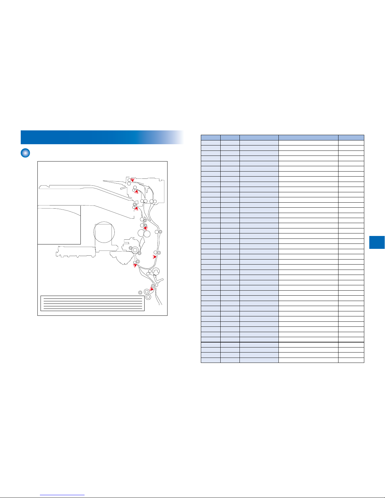
Jam Code
Main Unit
S1
S5
S7
S19
S12
S42
S40
F-3-1F-3-1
ACC ID Jam Code Type Sensor Name Sensor ID
3 0101 Delay jam
Cassette 1 pickup sensor S1
3 0102 Delay jam
Cassette 2 pickup sensor SR2
3 0103 Delay jam
Cassette 3 pickup sensor SR4
3 0104 Delay jam
Cassette 4 pickup sensor SR8
3 0105 Delay jam
Pre-registration sensor S5
3 0107 Delay jam
Fixing outlet sensor S19
3 0108 Delay jam
No. 1 delivery sensor S12
3 0109 Delay jam
No. 2 delivery sensor S42
3 010A Delay jam
Reversal sensor S40
3 010D Delay jam
Duplex feed sensor S7
3 0201 Stationary jam
Cassette 1 pickup sensor S1
3 0202 Stationary jam
Cassette 2 pickup sensor SR2
3 0203 Stationary jam
Cassette 3 pickup sensor SR4
3 0204 Stationary jam
Cassette 4 pickup sensor SR8
3 0205 Stationary jam
Pre-registration sensor S5
3 0207 Stationary jam
Fixing outlet sensor S19
3 0208 Stationary jam
No. 1 delivery sensor S12
3 0209 Stationary jam
No. 2 delivery sensor S42
3 020A Stationary jam
Reversal sensor S40
3 020D Stationary jam
Duplex feed sensor S7
3 0A01 Power-on jam
Cassette 1 pickup sensor S1
3 0A02 Power-on jam
Cassette 2 pickup sensor SR2
3 0A03 Power-on jam
Cassette 3 pickup sensor SR4
3 0A04 Power-on jam
Cassette 4 pickup sensor SR8
3 0A05 Power-on jam
Pre-registration sensor S5
3 0A07 Power-on jam
Fixing outlet sensor S19
3 0A08 Power-on jam
No. 1 delivery sensor S12
3 0A09 Power-on jam
No. 2 delivery sensor S42
3 0A0A Power-on jam
Reversal sensor S40
3 0A0D Power-on jam
Duplex feed sensor S7
3 0B00 Door open jam
- -
3 0CF1 Other jams
- -
3 0D91 Wrong size specied
Pre-registration sensor S5
3 FF00 Unknown jam
- -
3 FF01 Unknown jam
- -
3 FF02 Unknown jam
- -
3 FF03 Unknown jam
- -
3 FF04 Unknown jam
- -
3 FF05 Unknown jam
- -
3 FF07 Unknown jam
- -
3 FF08 Unknown jam
- -
3 FF09 Unknown jam
- -
3 FF0A Unknown jam
- -
 Loading...