

Canon imageRUNNER 2525 Series, imageRUNNER 2520 Series, imageRUNNER 2530 Series Service Manual

imageRUNNER
2530/2525/2520 Series
Service Manual
Revision 9.0

1x
1x
Introduction
Introduction
Important Notices
Application
This manual has been issued by Canon Inc. for qualified persons to learn technical theory, installation, maintenance, and repair
of products.
This manual covers all localities where the products are sold. For this reason, there may be information in this manual that does
not apply to your locality.
Corrections
This manual may contain technical inaccuracies or typographical errors due to improvements or changes in products.
When changes occur in applicable products or in the contents of this manual, Canon will release technical information as the
need arises. In the event of major changes in the contents of this manual over a long or short period, Canon will issue a new
edition of this manual.
The following paragraph does not apply to any countries where such provisions are inconsistent with local law.
Trademarks
The product names and company names used in this manual are the registered trademarks of the individual companies.
Copyright
This manual is copyrighted with all rights reserved. Under the copyright laws, this manual may not be copied, reproduced or
translated into another language, in whole or in part, without the consent of Canon Inc.
Copyright CANON INC. 2015
Caution
Use of this manual should be strictly supervised to avoid disclosure of confidential information.
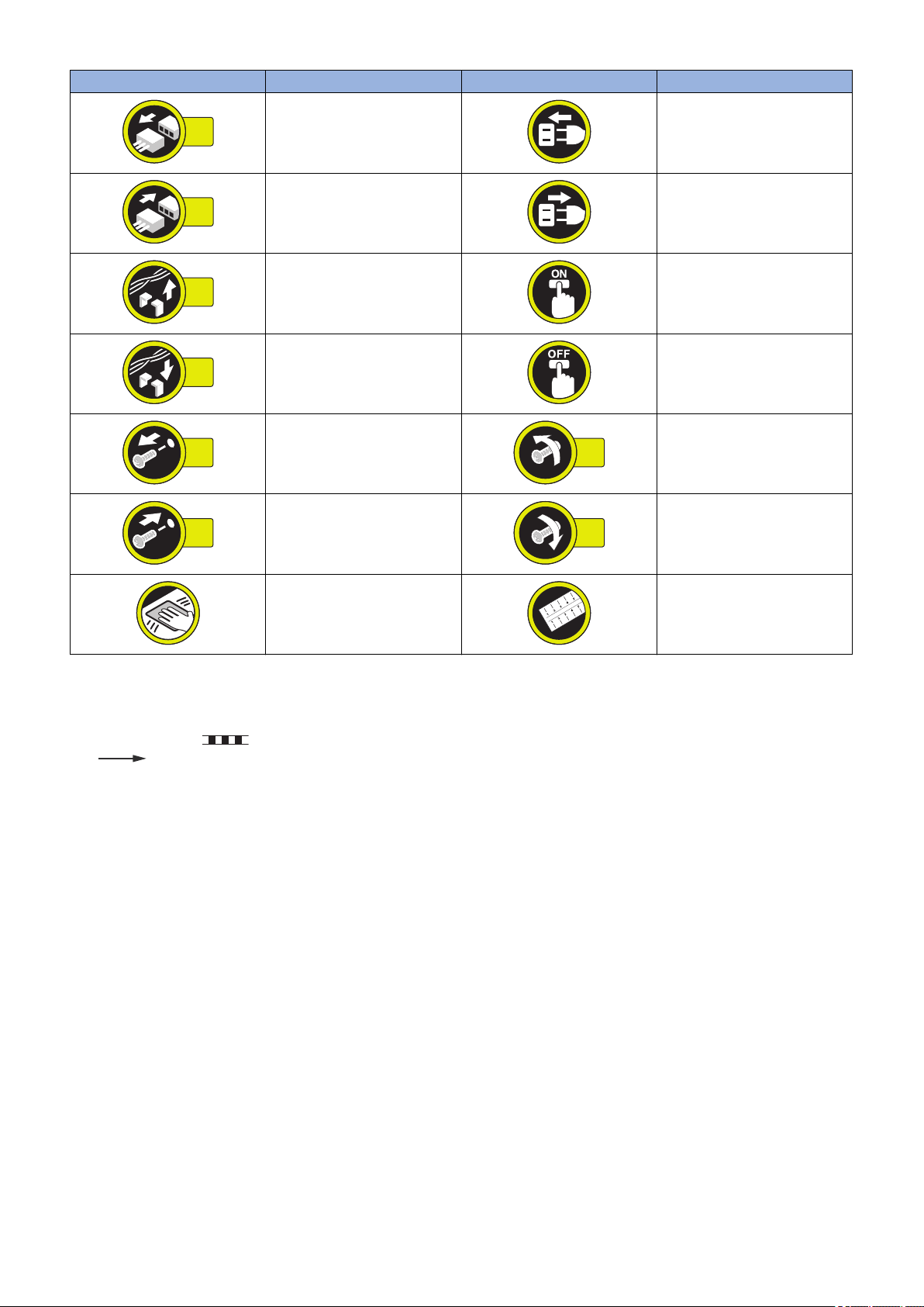
Explanation of Symbols
The following symbols are used throughout this Service Manual.
Symbols Explanation Symbols Explanation
Check.
Remove the claw.
Check visually.
Check a sound. Push the part.
Insert the claw.
1x
1x
1x
1x
1x
1x
1x
1x
Introduction
Symbols Explanation Symbols Explanation
Disconnect the connector. Connect the power cable.
Connect the connector. Disconnect the power cable.
Remove the cable/wire from the
cable guide or wire saddle.
Install the cable/wire to the cable
guide or wire saddle.
Remove the screw.
Install the screw.
Cleaning is needed. Measurement is needed.
The following rules apply throughout this Service Manual:
1. Each chapter contains sections explaining the purpose of specific functions and the relationship between electrical and
mechanical systems with reference to the timing of operation.
In the diagrams, represents the path of mechanical drive; where a signal name accompanies the symbol, the arrow
indicates the direction of the electric signal.
The expression "turn on the power" means flipping on the power switch, closing the front door, and closing the delivery unit
door, which results in supplying the machine with power.
2. In the digital circuits, '1' is used to indicate that the voltage level of a given signal is "High", while '0' is used to indicate "Low".
(The voltage value, however, differs from circuit to circuit.) In addition, the asterisk (*) as in "DRMD*" indicates that the DRMD
signal goes on when '0'.
In practically all cases, the internal mechanisms of a microprocessor cannot be checked in the field. Therefore, the operations
of the microprocessors used in the machines are not discussed: they are explained in terms of from sensors to the input of
the DC controller PCB and from the output of the DC controller PCB to the loads.
The descriptions in this Service Manual are subject to change without notice for product improvement or other purposes, and
major changes will be communicated in the form of Service Information bulletins.
All service persons are expected to have a good understanding of the contents of this Service Manual and all relevant Service
Information bulletins and be able to identify and isolate faults in the machine.
Turn on the power.
Turn off the power.
Loosen the screw.
Tighten the screw.

Contents
Contents
Safety Precautions...............................................................................................1
Laser Safety........................................................................................................................................ 2
Handling of Laser System................................................................................................................... 2
Turn Power Switch ON........................................................................................................................2
Power Supply...................................................................................................................................... 3
Safety of Toner....................................................................................................................................3
About Toner..........................................................................................................................................3
Toner on Clothing or Skin...................................................................................................................... 4
Notes When Handling a Lithium Battery............................................................................................. 4
Notes Before Servicing........................................................................................................................4
Points to Note at Cleaning...................................................................................................................4
Notes On Assembly/Disassembly....................................................................................................... 5
Notes on Assembly / Disassembly..........................................................................................................5
1. Product Overview.............................................................................................6
Product Lineup.................................................................................................................................... 7
Host machine........................................................................................................................................7
Option.................................................................................................................................................. 8
Features............................................................................................................................................ 10
Product feature................................................................................................................................... 10
Specifications.................................................................................................................................... 11
Specifications..................................................................................................................................... 11
Power consumption.............................................................................................................................12
Weight / Size...................................................................................................................................... 12
Productivity (Print speed).....................................................................................................................13
Paper type..........................................................................................................................................13
Name of Parts................................................................................................................................... 15
External View......................................................................................................................................15
Cross Sectional View (550-sheet 1st cassete model).............................................................................16
Cross Sectional View (250-sheet 1st cassette model)............................................................................17
Operation...........................................................................................................................................18
Power Switch......................................................................................................................................18
Control Panel......................................................................................................................................18
2. Technical Explanation................................................................................... 20
Basic Configuration........................................................................................................................... 21
Functional Configuration......................................................................................................................21
Basic Sequence..................................................................................................................................21
Original Exposure System.................................................................................................................23
Overview............................................................................................................................................ 23
Controls..............................................................................................................................................26
Controller System..............................................................................................................................36
Overview............................................................................................................................................ 36
Controls..............................................................................................................................................38
i

Contents
Laser Exposure System.................................................................................................................... 47
Overview............................................................................................................................................ 47
Controls..............................................................................................................................................49
Image Formation System.................................................................................................................. 53
Overview............................................................................................................................................ 53
Controls..............................................................................................................................................56
Fixing System....................................................................................................................................66
Overview............................................................................................................................................ 66
Controls..............................................................................................................................................68
Pickup/Feed System......................................................................................................................... 76
Overview............................................................................................................................................ 76
Controls..............................................................................................................................................86
Embedded RDS................................................................................................................................ 97
Product Overview................................................................................................................................97
E-RDS Setup...................................................................................................................................... 97
FAQ................................................................................................................................................. 103
Troubleshooting................................................................................................................................ 103
Service cautions................................................................................................................................108
3. Periodical Service........................................................................................ 109
Consumable Parts and Cleaning Parts........................................................................................... 110
Cleaning Parts.................................................................................................................................115
4. Disassembly/Assembly............................................................................... 116
List of Parts..................................................................................................................................... 117
List of Covers....................................................................................................................................117
List of Main Units / Parts.................................................................................................................... 119
List of Clutches/Solenoids..................................................................................................................120
List of Motors.................................................................................................................................... 122
List of Fans.......................................................................................................................................123
List of Switches................................................................................................................................. 124
List of Lamp,Heater,Others................................................................................................................ 125
List of Sensors.................................................................................................................................. 126
List of PCBs......................................................................................................................................128
External / Internal Cover..................................................................................................................130
Removing the Reader Left Cover....................................................................................................... 130
Removing the Reader Front Cover..................................................................................................... 130
Removing the Support Cover............................................................................................................. 130
Removing the Delivery Tray............................................................................................................... 130
Removing the Front Cover................................................................................................................. 131
Removing the Lower Left Cover......................................................................................................... 131
Removing the Left Cover................................................................................................................... 132
Removing the Inside Base Cover....................................................................................................... 133
Installing the Inside Base Cover......................................................................................................... 133
Removing the Left Rear Cover........................................................................................................... 134
Removing the Toner Supply Cover..................................................................................................... 134
Removing the Reader Right Cover..................................................................................................... 135
Removing the Platen Glass................................................................................................................135
Removing the Reader Rear Cover......................................................................................................136
ii

Contents
Removing the Rear Cover (Right).......................................................................................................136
Removing the Rear Cover (Left).........................................................................................................137
Removing the Rear Right Cover (Upper).............................................................................................137
Removing the Rear Right Cover (Lower).............................................................................................137
Removing the Lower Rear Cover........................................................................................................138
Removing the Cassette 2 Rear Cover.................................................................................................138
Main Unit......................................................................................................................................... 139
Removing the Right Cover Assembly..................................................................................................139
Removing the Cassette Pickup Assembly (550-sheet 1st Cassette Model)............................................140
Removing the Cassette Pickup Assembly 1 (250-sheet 1st cassette Model)..........................................141
Removing the Cassette Pickup Assembly 2 (250-sheet 1st cassette Model)..........................................141
Removing the Laser Scanner Unit...................................................................................................... 142
Removing the Toner Supply Assembly................................................................................................143
Removing the CIS Unit...................................................................................................................... 145
Removing the Platen Glass................................................................................................................146
Removing the ADF Scan Glass.......................................................................................................... 147
Removing the Control Panel Assembly............................................................................................... 148
Removing the Multi Pickup Assembly................................................................................................. 148
Periodic Replacing Parts,Durable Parts,Cleaning Parts................................................................. 150
Removing the Transfer Roller.............................................................................................................150
Removing the Separation Static Charge Eliminator..............................................................................150
Removing the Waste Toner Container................................................................................................ 150
Removing the Drum Unit....................................................................................................................151
Removing the Developing Assembly...................................................................................................151
Removing the Manual Feed Pickup Roller...........................................................................................152
Removing the Manual Feed Separation Pad....................................................................................... 152
Removing the Fixing Unit...................................................................................................................153
Removing the Cassette Pickup Roller (250-sheet 1st cassette Model).................................................. 153
Removing the Roller Cassette Separation Pad(250-sheet 1st cassette Model)...................................... 153
Removing the Cassette Pickup Roller (550-sheet 1st cassette Model).................................................. 154
Removing the Cassette Feed Roller (550-sheet 1st cassette Model).....................................................154
Removing the Cassette Separation Roller (550-sheet 1st cassette Model)............................................ 154
Removing the Idler Gear (Only for 550-sheet 1st cassette Model for China).......................................... 154
Clutch / Solenoid............................................................................................................................. 156
Removing the Clutch (CL1/CL2/CL3/CL4)...........................................................................................156
Removing the No. 1 Delivery Reversal Solenoid (SL3).........................................................................156
Motor............................................................................................................................................... 159
Removing the Main Motor (M1).......................................................................................................... 159
Removing the Fixing Motor (M2).........................................................................................................159
Removing the Cassette 1 Pickup Motor (M3).......................................................................................160
Removing the Reversal Motor (M10).................................................................................................. 161
Removing the Scanner Motor (M31)................................................................................................... 161
Fan.................................................................................................................................................. 163
Removing the Power Supply Cooling Fan (FAN6)................................................................................163
Switch..............................................................................................................................................164
Removing the Front Door Switch (SW2)..............................................................................................164
Removing the Cassette Size Detection Switch (SW6/ SW7).................................................................165
Lamp,Heater,others.........................................................................................................................167
Removing the Fixing Film Unit............................................................................................................167
Removing the Pressure Roller............................................................................................................170
PCB.................................................................................................................................................171
iii

Contents
Removing the Main Controller PCB.................................................................................................... 171
Removing the Reader Relay PCB.......................................................................................................171
Removing the Power Supply PCB...................................................................................................... 172
Removing the DC Controller PCB.......................................................................................................172
Removing the HVT PCB.................................................................................................................... 173
Removing the Option Power Supply PCB............................................................................................173
Removing the Heater PCB.................................................................................................................174
Removing the RAM PCB....................................................................................................................174
5. Adjustment................................................................................................... 177
Overview......................................................................................................................................... 178
Adjustment when replacing parts........................................................................................................178
Image position adjustment................................................................................................................. 178
Basic Adjustment.............................................................................................................................180
Image position adjustment................................................................................................................. 180
Adjustment when Replacing the Parts............................................................................................ 182
Original Exposure..............................................................................................................................182
Main Controller..................................................................................................................................183
Laser Exposure System.....................................................................................................................184
6. Troubleshooting...........................................................................................185
Initial Check.....................................................................................................................................186
Initial check items list.........................................................................................................................186
Test Print.........................................................................................................................................188
Overview.......................................................................................................................................... 188
Select the test print TYPE.................................................................................................................. 188
Troubleshooting Items.....................................................................................................................189
Troubleshooting items list.................................................................................................................. 189
Image Faults.....................................................................................................................................189
Version Upgrade............................................................................................................................. 194
Overview.......................................................................................................................................... 194
Procedure.........................................................................................................................................195
Service Call Request Function........................................................................................................198
7. Error/Jam/Alarm........................................................................................... 199
Outline.............................................................................................................................................200
Error Code.......................................................................................................................................201
Error Code Details.............................................................................................................................201
FAX Error Code................................................................................................................................ 209
Jam Code........................................................................................................................................213
Main Unit.......................................................................................................................................... 213
DADF-AB1........................................................................................................................................216
Inner Finisher-B1...............................................................................................................................217
Alarm Code..................................................................................................................................... 219
Alarm Code Details........................................................................................................................... 219
8. Service Mode................................................................................................ 221
Overview......................................................................................................................................... 222
iv

Contents
Outline of Service Mode.....................................................................................................................222
Using the Mode.................................................................................................................................223
Setting of Bit Switch...........................................................................................................................223
Back-Up........................................................................................................................................... 224
Service Label....................................................................................................................................224
Details of Service Mode.................................................................................................................. 225
#SSSW.............................................................................................................................................225
#MENU.............................................................................................................................................238
#NUMERIC.......................................................................................................................................239
#SCAN............................................................................................................................................. 247
#PRINT............................................................................................................................................ 260
#NETWORK..................................................................................................................................... 268
#CODEC.......................................................................................................................................... 270
#SYSTEM.........................................................................................................................................271
#ACC............................................................................................................................................... 278
#COUNTER......................................................................................................................................279
#LMS............................................................................................................................................... 280
#E-RDS............................................................................................................................................284
#REPORT........................................................................................................................................ 284
#DOWNLOAD...................................................................................................................................290
#CLEAR........................................................................................................................................... 291
#DISPLAY........................................................................................................................................ 292
#ROM...............................................................................................................................................292
#TEST MODE...................................................................................................................................292
Remote UI Service Mode................................................................................................................ 302
Function Overview.............................................................................................................................302
How to Use.......................................................................................................................................303
Report Display Function.....................................................................................................................303
9. Installation.................................................................................................... 305
How to check this Installation Procedure........................................................................................ 306
Illustrations Used in This Procedure....................................................................................................306
Symbols in the Illustration.................................................................................................................. 306
Checking before Installation............................................................................................................307
Checking Power Supply.....................................................................................................................307
Checking the Installation Environment................................................................................................ 307
Checking Installation Space............................................................................................................... 307
Points to Make Before Installation.......................................................................................................307
Option Installation Sequence..............................................................................................................308
Unpacking....................................................................................................................................... 309
Unpacking the Machine and Removing the Packaging Materials.......................................................... 309
Checking the Contents....................................................................................................................310
Installation Procedure......................................................................................................................312
Installing the Toner Bottle.................................................................................................................. 312
Installing the Drum Unit......................................................................................................................312
Installing Trays..................................................................................................................................314
Setting the Cassettes.........................................................................................................................315
Installing Other Parts......................................................................................................................... 316
Connecting the Cord..........................................................................................................................318
Initial Settings (Start Setup Guide)......................................................................................................319
v

Contents
Checking the Print Image...................................................................................................................319
Setting the Cassette Heater (if equipping with the cassette heater).......................................................320
Document Tray-J1...........................................................................................................................321
Points to Note before Installation........................................................................................................ 321
Checking the Contents...................................................................................................................... 321
Installation Procedure........................................................................................................................322
Card Reader-F1.............................................................................................................................. 324
Checking the Contents...................................................................................................................... 324
Checking before Installation............................................................................................................... 324
Installation Procedure........................................................................................................................324
Registering the Card IDs....................................................................................................................330
Serial Interface Kit-J2......................................................................................................................332
Checking before Installation............................................................................................................... 332
Checking the Contents...................................................................................................................... 332
Installation Procedure........................................................................................................................332
Copy Control Interface Cable-A1.................................................................................................... 335
Checking before Installation............................................................................................................... 335
Checking the Contents...................................................................................................................... 335
Installation Procedure........................................................................................................................335
System Upgrade RAM-C1...............................................................................................................338
Checking before Installation............................................................................................................... 338
Checking the Contents...................................................................................................................... 338
Installation Procedure........................................................................................................................338
Cst Heater Kit-J1.............................................................................................................................341
Checking Before Installation...............................................................................................................341
Checking the Contents...................................................................................................................... 341
Installation Procedure........................................................................................................................341
Checking after Installation..................................................................................................................347
Reader Heater Unit......................................................................................................................... 348
Checking Before Installation...............................................................................................................348
Checking the Contents (For 230V)......................................................................................................348
Checking the Parts to be Installed (For 120V)......................................................................................348
Installation Procedure........................................................................................................................348
Checking after Installation..................................................................................................................354
Cassette Heater Unit-37..................................................................................................................355
Checking Before Installation...............................................................................................................355
Checking the Contents...................................................................................................................... 355
Installation Procedure........................................................................................................................355
Checking after Installation..................................................................................................................367
Drum Heater-C1..............................................................................................................................368
Checking before Installation............................................................................................................... 368
Checking the Contents...................................................................................................................... 368
Installation Procedure........................................................................................................................368
Checking after Installation..................................................................................................................376
APPENDICES....................................................................................................377
Service Tools...................................................................................................................................378
Special Tools.................................................................................................................................... 378
Oils and Solvents.............................................................................................................................. 378
General Circuit Diagram..................................................................................................................379
vi

Contents
General Circuit Diagram (550-sheet 1st cassette type).........................................................................379
General Circuit Diagram (250-sheet 1st cassette type).........................................................................386
vii

Safety Precautions
Laser Safety..........................................2
Handling of Laser System.....................2
Turn Power Switch ON..........................2
Power Supply........................................3
Safety of Toner......................................3
Notes When Handling a Lithium
Battery............................................... 4
Notes Before Servicing......................... 4
Points to Note at Cleaning.................... 4
Notes On Assembly/Disassembly.........5
Safety Precautions
Laser Safety
Since radiation emitted inside the machine is completely confined within protective housings and external covers, the laser beam
cannot escape from the machine during any phase of user operation.
Therefore this machine is classified in Class 1 laser products that are regarded as safe during normal use according to
International Standard IEC60825-1.
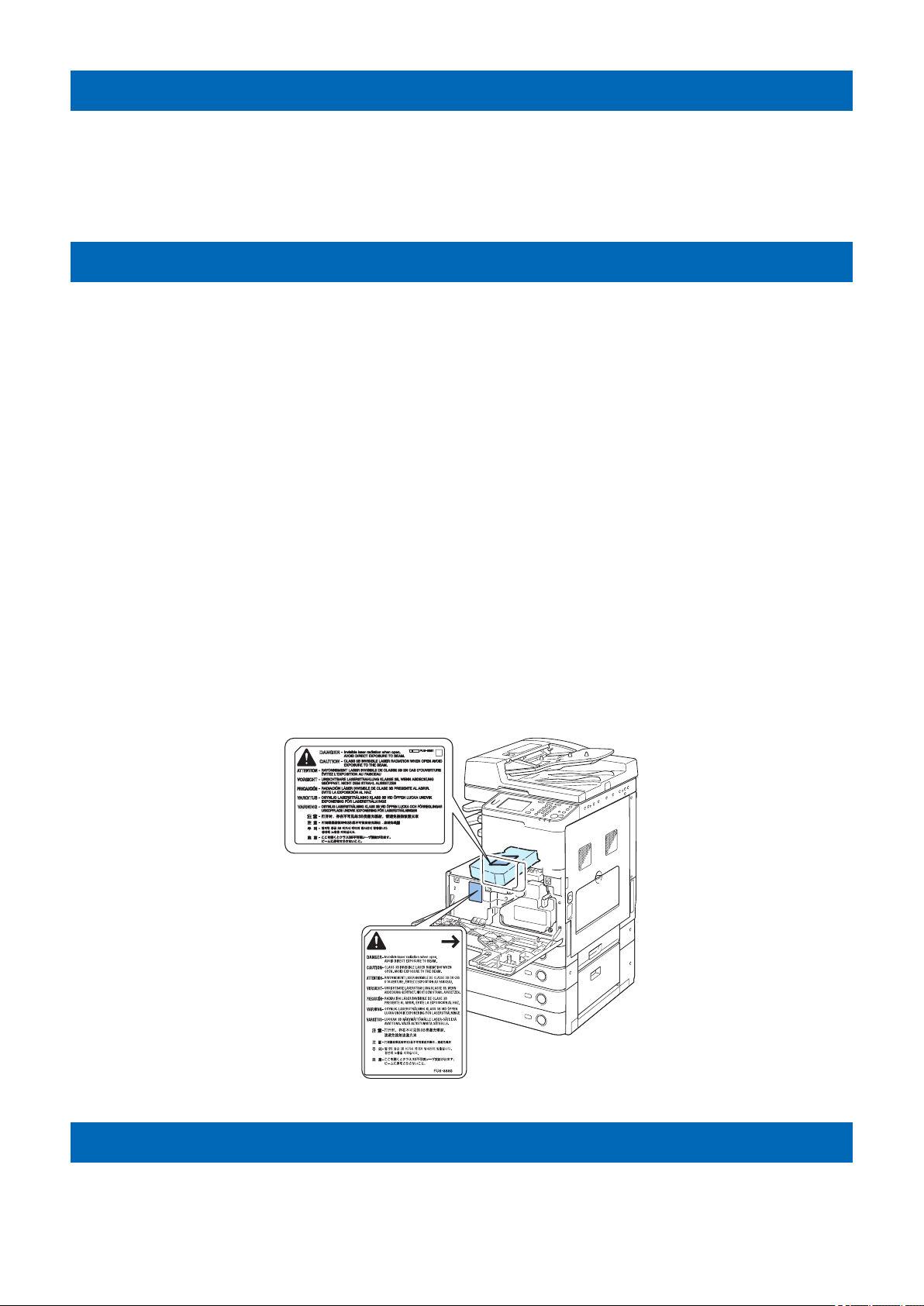
Handling of Laser System
This machine is classified in Class 1 laser products.
However, inside the machine, Class 3B laser beam is emitted and is hazardous when entered into an eye.
When servicing the area around the laser assembly, be sure to turn off the main power.
If you must service while the power is turned on, be sure to keep the followings:
- Do not use a screwdriver or tools that have a high level of reflectance in the laser path.
- Remove watches and rings before starting the work. (They can reflect the laser beam, possibly hitting an eye.)
The machine's covers that confine laser beam radiation are identified by means of warning label (Figure). If you must open the
cover, be sure not to enter the laser beam into an eye during the work.
The following warnings are given to comply with Safety Principles (EN60950-1).
Diese Maschine ist der Klasse 1 der Laserprodukte zugeordnet.
Innerhalb der Maschine wird jedoch ein Laserstrahl der Klasse 3B ausgestrahlt und es ist gefährlich, wenn dieser Strahl in die
Augen gerät.
Bei Servicearbeiten am oder in der Nähe des Laserteils zuerst das Hauptgerät abschalten.
Bei Servicearbeiten, die unbedingt bei eingeschaltetem Gerät durchgeführt werden müssen, auf jeden Fall die folgenden
Vorsichtsmaßnahmen beachten.
- Keine stark reflektierenden Schraubenzieher oder ähnliche Werkzeuge direkt in den Lichtpfad des Laserstrahls bringen.
- Vor Beginn der Arbeit Uhren, Ringe und ähnliche Gegenstände abnehmen. (Reflektierende Laserstrahlen könnten sonst in die
Augen geraten.)
Die Geräte-Abdeckungen, die Laserstrahlen reflektieren können, werden durch einen besonderen Warnaufkleber
gekennzeichnet (siehe Bild).
Muss die Abdeckung geöffnet werden, besondere Vorsicht walten lassen, damit der Laserstrahl nicht in die Augen gerät.
Turn Power Switch ON
The machine is equipped with 2 power switches: main power switch and control energy saver key.
The machine goes on when the main power switch is turned on (i.e., other than in low power mode, sleep mode).
2
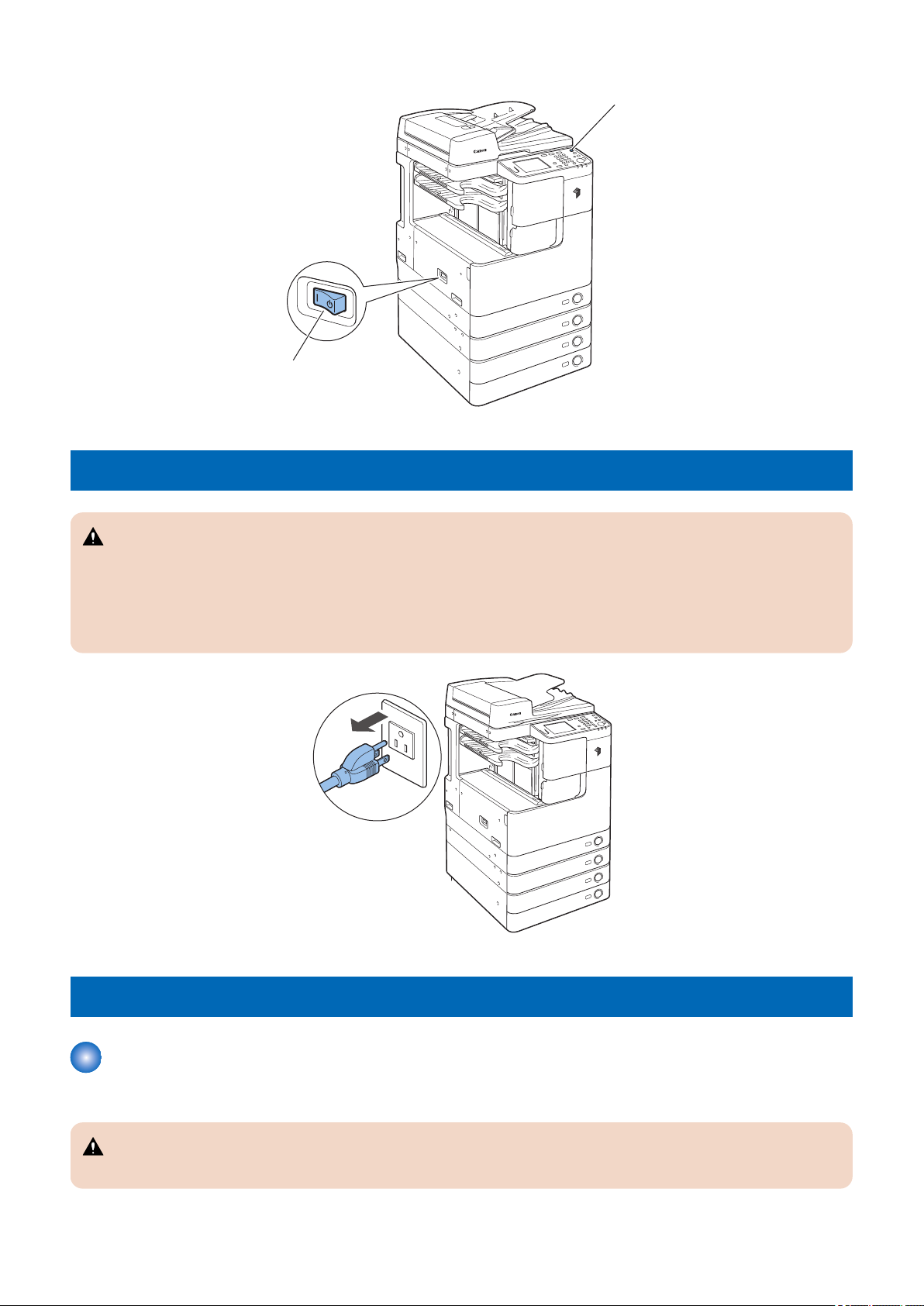
Main power switch
Control panel
power switch
Power Supply
Safety Precautions
CAUTION:
1. As a general rule, do not use extension cords. Using an extension cord may result in a fire or electrical shock. If an
extension cord must be used, however, use one for local rated voltage and over, untie the cord binding, and insert the
power plug completely into the extension cord outlet to ensure a firm connection between the power cord and the
extension cord.
2. The socket-outlet shall be installed near the equipment and shall be easily accessible.
Safety of Toner
The machine's toner is a non-toxic material made of plastic, iron, and small amounts of dye.
Do not throw toner into fire. It may cause explosion.
About Toner
CAUTION:
3
Toner on Clothing or Skin
• If your clothing or skin has come into contact with toner, wipe it off with tissue; then, wash it off with water.
• Do not use warm water, which will cause the toner to jell and fuse permanently with the fibers of the cloth.
• Toner is easy to react with plastic material, avoid contact with plastic.
Notes When Handling a Lithium Battery
CAUTION:
RISK OF EXPLOSION IF BATTERY IS REPLACED BY AN INCORRECT TYPE.
DISPOSE OF USED BATTERIES ACCORDING TO THE INSTRUCTIONS.
The following warnings are given to comply with Safety Principles (EN60950).
CAUTION:
Wenn mit dem falschen Typ ausgewechselt, besteht Explosionsgefahr.
Gebrauchte Batterien gemäß der Anleitung beseitigen.
Safety Precautions
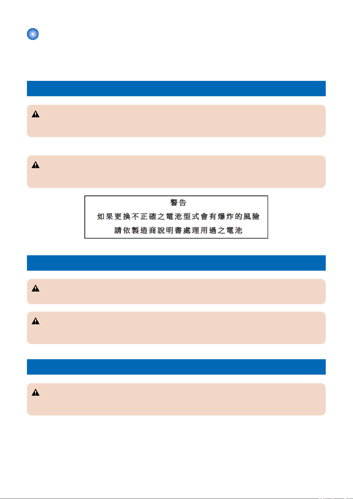
Notes Before Servicing
CAUTION:
At servicing, be sure to turn off the power source according to the specified steps and disconnect the power plug.
CAUTION:
Do not turn off the power switch when downloading is under way. Turning off the main power switch while downloading is
under way can disable the machine.
Points to Note at Cleaning
CAUTION:
When performing cleaning using organic solvent such as alcohol, be sure to check that the component of solvent is
vaporized completely before assembling.
4

Safety Precautions
Notes On Assembly/Disassembly
Notes on Assembly / Disassembly
Follow the items below to assemble/disassemble the device.
1. Disconnect the power plug to avoid any potential dangers during assembling/disassembling works.
2. If not specially instructed, reverse the order of disassembly to reinstall.
3. Ensure to use the right screw type (length, diameter, etc.) at the right position when assembling.
4. To keep electric conduction, binding screws with washers are used to attach the grounding wire and the varistor. Ensure to
use the right screw type when assembling.
5. Unless it is specially needed, do not operate the device with some parts removed.
6. Never remove the paint-locked screws when disassembling.
7. During disassembly, reassembly or transportation of the printer, remove the cartridge if required.
When the cartridge is out of the printer, put it in a protective bag even in a short period of time to prevent the adverse effect
of light.
8. Ground yourself by touching the metal part of the printer before handling the PCB to reduce the possibility of damage caused
by static electricity.
9. When you replace the part that the rating plate or the product code label is attached, be sure to remove the rating plate or
the product code label and put it to the new part.
5

1
Product Overview
Product Lineup......................................7
Features..............................................10
Specifications......................................11
Name of Parts..................................... 15
Operation............................................ 18
Product Lineup
Host machine
1. Product Overview
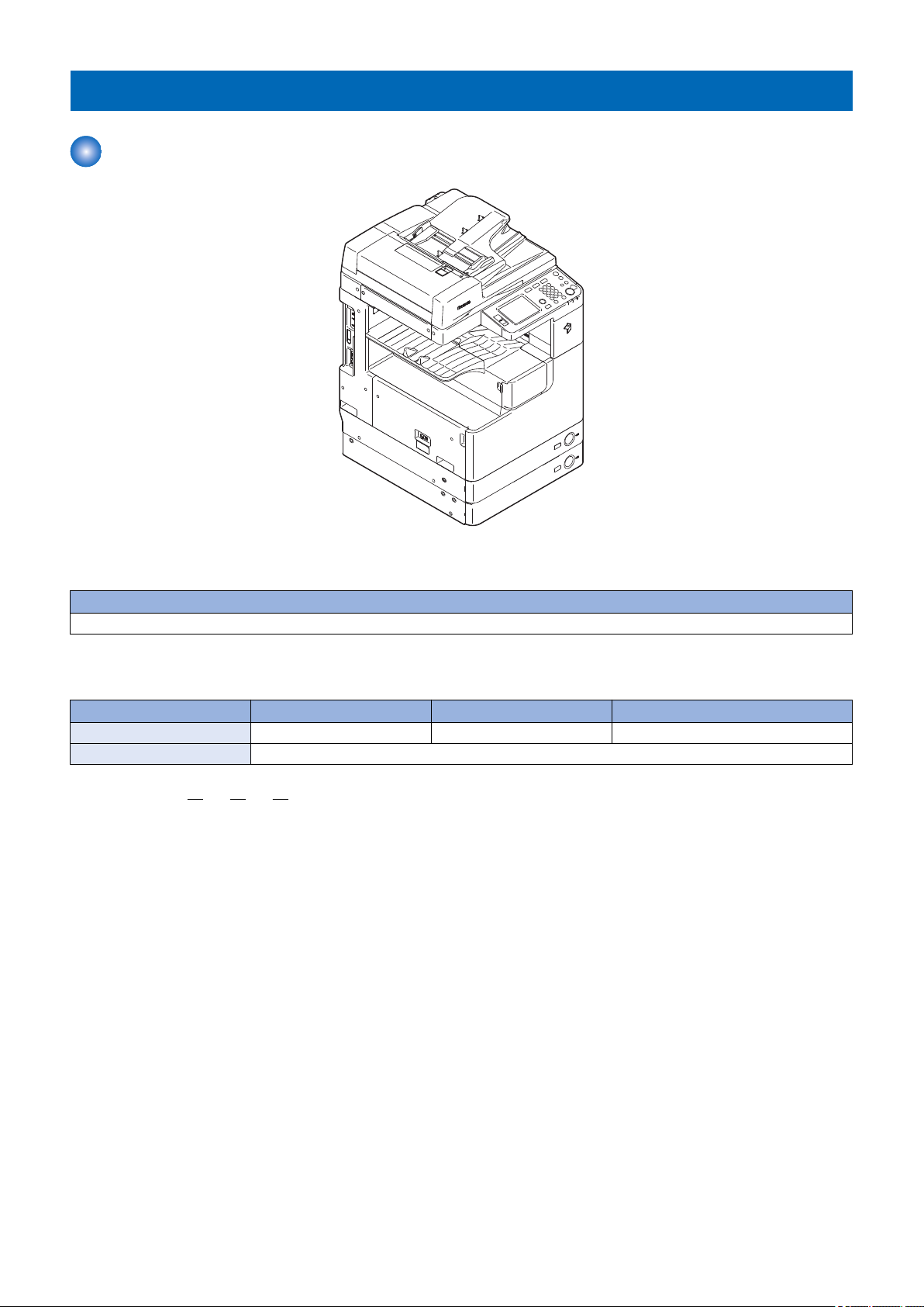
■ Host machine configuration
Host machine configuration
Reader + DADF (standard or optional) + Printer
■ Model type
imageRUNNER 2530 imageRUNNER 2525 imageRUNNER 2520
Print Speed 30ppm 25ppm 20ppm
Positioning Target machine: imageRUNNER 2025/2022/2018 Series
imageRUNNER 2530 / 2525 / 2520
Underlined (2-digit) numeric figures indicate print speed (ppm: print per minute).
7
Option
[4]
[2]
[1]
[3]
[5]
[6]
[7]
[8]
[11]
[9]
[10]
[12]
[13]
[14]
[15]
[16]
[17]
[18]
[20]
[19]
[21]
[22]
[23]
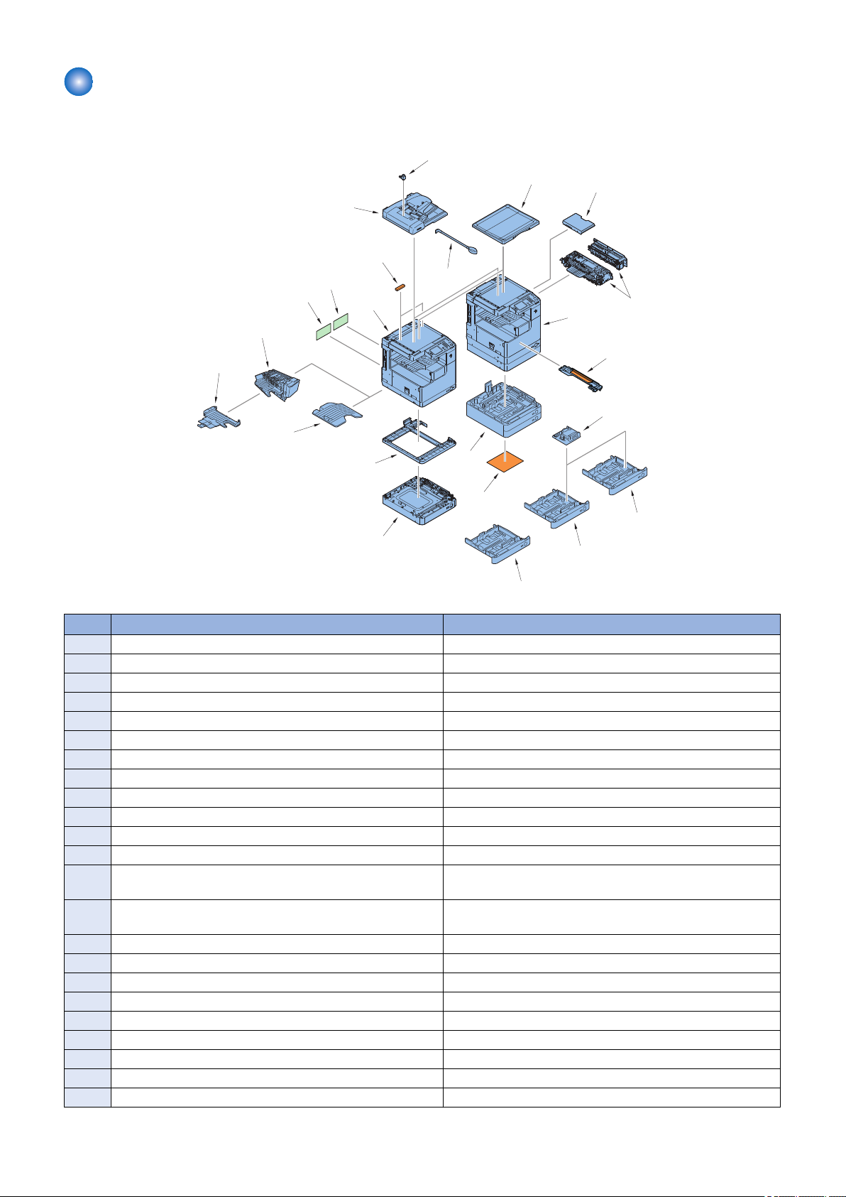
■ Pickup delivery / image reading options
1. Product Overview
No. Product name Remarks and condition
1 imageRUNNER 2530/2525/2520
2 imageRUNNER 2530/2525
3 DADF-AB1
4 Inner Finisher Additional Tray-B1
5 Inner Finisher-B1 Built-in finisher Power Supply Unit-U1 is required.
6 Reader Heater Unit-H1 Cst Heater Kit-J1 is required.
7 Platen Cover Type P
8 Document Tray-J1
9 FL Cassette-AJ1
10 FL Cassette-AK1
11 FL Cassette-AL1
12 Cassette Heater Unit-37 Cst Heater Kit-J1 is required.
13 Cassette Module-W1 Cassette Spacer-A1 is required when installing to 250 Sheets
14 CST. Feeding Unit-AE1 Cassette Spacer-A1 is required when installing to 250 Sheets
15 Envelope Feeder Attachment-D1
16 Cassette Spacer-A1
17 Inner 2Way Tray-G1 For host machine delivery additional tray.
18 Cst Heater Kit-J1
19 Drum Heater-C1 Cst Heater Kit-J1 is required.
20 Power Supply Unit-U1
21 ADF Access Handle-A1
22 2 Way Unit-B1
23 Stamp Unit-B1
Cassette Model.
Cassette Model.
8
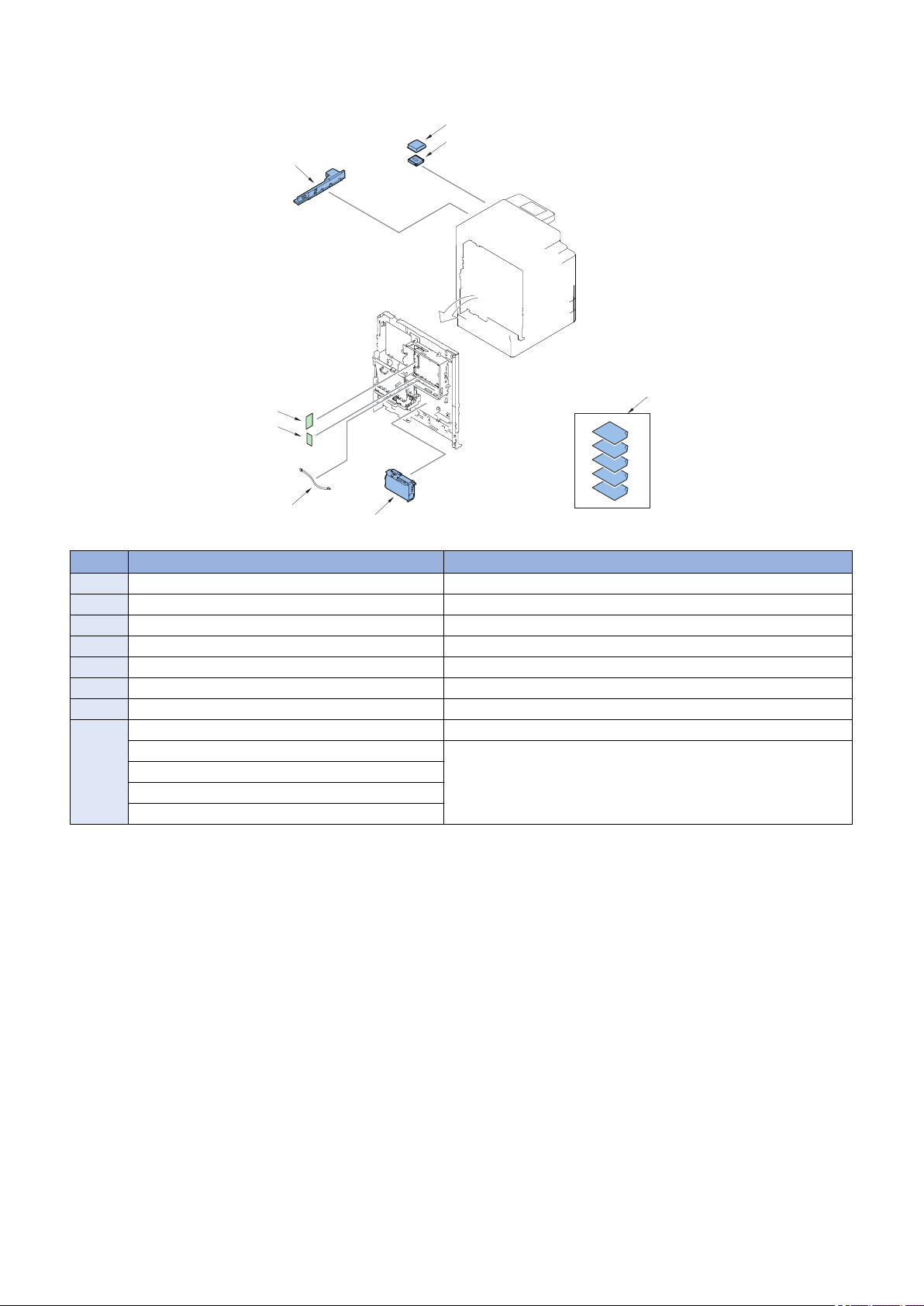
■ Function expanding option
[1]
[2]
[3]
[4]
[5]
[6]
[7]
[8]
1. Product Overview
No. Product name Remarks and condition
1 Card Reader-E1 or Card Reader-F1 Card Reader Attachment-D3 is required.
2 Card Reader Attachment-D3
3 Super G3 Fax Board-AG1
4 USB Application 3-Port Interface Kit-A1
5 Serial Interface Kit-J2
6 System Upgrade RAM-C1
7 Copy Control Interface Cable-A1
8 Barcode Printing Kit-B1 PCL Printer Kit-AF1 is required.
PCL Printer Kit-AF1 512MB RAM should be installed.
PS Printer Kit-AF1
Color Send Kit-Y1
Color Send Searchable PDF Kit-C1
In the case of 256MB, System Upgrade RAM-C1 (512MB) is needed.
9
Features
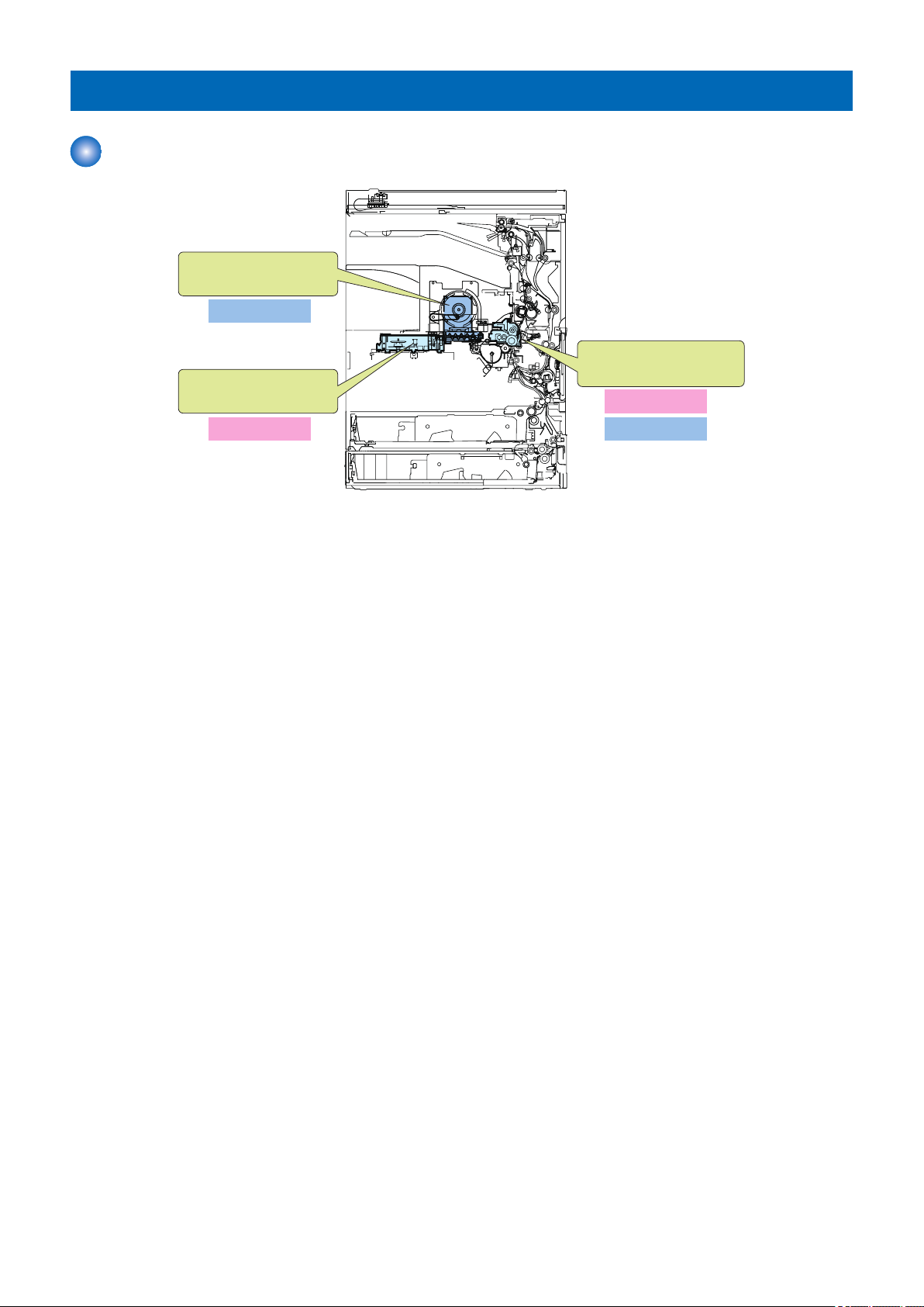
Drum unit
- Highly-durable OPC drum is
adopted.
High image quality
Laser scanner unit
- Capable of 1200 dpi
Waste toner container
- User replaceable
Low running cost
High image quality
Low running cost
Product feature
1. Product Overview
10

1. Product Overview
Specifications
Specifications
Item Specifications
Copyboard Stream reading, original fixed reading
Body Desktop
Light source type LED (RGB)
Photosensitive medium OPC drum (30 mm dia)
Image reading method CIS
Reproduction method Indirect electrostatic method
Exposure method Laser exposure system
Charging method Roller charge
Development method Dry single component projection developing
Transfer method By transfer roller
Separation method Curvature and static eliminator
Pickup method 550 sheets cassette: Retard separation method
250 sheets cassette: Pad separation method
Manual feed pickup tray: Pad separation method
Fixing method On demand
Delivery method Face down delivery (in-body delivery)
Reproduction ratio 25% to 400%
Drum cleaning method By cleaning blade
Toner type Magnetic negative charge toner
Toner replenish method Toner cartridge
Toner level detection function Yes
Top margin 2.5 -/+ 1.5 mm
Left margin 2.5 -/+ 1.5 mm
Non-image width (leading edge) 2.5 -/+ 1.5 mm
Non-image width (left edge) 2.5 -/+ 1.5 mm * Using the feeder: 2.5 -/+ 2.0 mm
Warm-up time At power ON: 30 sec or less
Number of gradations 256 gradations
Reading resolution 600 dpi x 600 dpi
Writing resolution 1200 dpi x 1200 dpi
First print time imageRUNNER 2530/2525: 5.4 sec or less
imageRUNNER 2520: 6.4 sec or less
Paper type (Cassette 1/3/4)
Paper type (Cassette 2)
Paper type (Manual feed pickup tray)
Paper size (Cassette 1/3/4) Standard size (A4, A4R, A3, A5R, B4, B5, B5R, LTR, LTTR, LG, 279mmX432mm(11"X17"),
Paper size (Cassette 2) Standard size (A4, A4R, A3, A5R, B4, B5, B5R, LTR, LTTR, LG, 279mmX432mm(11"X17"),
Paper size (Manual feed pickup tray) Standard size (A4, A4R, A3, A5R, B4, B5, B5R, LTR, LTTR, LG, 279mmX432mm(11"X17"),
Pickup capacity
Weight: 64 g/m2 to 90 g/m2 Type: Plain, Recycled, Color (64 g/m2 to 80 g/m2), 3-hole punch
Weight: 64 g/m2 to 90 g/m
Type: Plain, Recycled, Color (64 g/m2 to 80 g/m2), 3-hole punch, Envelopes* (No.10 (COM10),
ISO-B5, Monarch, ISO-C5, DL)
* The optional Envelope Feeder Attachment-D1 is required.
Weight: 64 g/m2 to 128 g/m
Type: Plain, Recycled, Color (64 g/m2 to 80 g/m2), 3-hole punch, Bond (75 g/m2 to 90 g/m2),
Heavy Paper 1 (81 g/m2 to 90 g/ m2), Heavy Paper 2 (91 g/m2 to 105 g/m2), Heavy Paper 3 (106
g/m2 to 128 g/m2), Transparencies, Labels, Envelopes (No.10 (COM10), ISO-B5, Monarch, ISO-
C5, DL)
STMTR,EXEC,8K,16K,16KR)
STMTR) Envelopes* (No.10 (COM10), ISO-B5, Monarch, ISO-C5, DL)
* The optional Envelope Feeder Attachment-D1 is required.
STMTR) Free size (99 mm x 297 mm to 148 mm x 432 mm) Envelopes (No.10 (COM10), ISOB5, Monarch, ISO-C5, DL)
550 sheets cassette: 550 sheets (80g/m2) 550 sheets cassette: 250 sheets (80g/m2) Manual
feed pickup tray: 100 sheets (80g/m2)
2
2
11

Item Specifications
Duplex method Through path duplex
Acoustic noise imageRUNNER 2530:
operation: 69.50 dB or less *1 / stand-by: 43.00 dB or less *2
imageRUNNER 2525:
operation: 67.75 dB or less *1 / stand-by: 43.00 dB or less *2
imageRUNNER 2520:
operation: 66.00 dB or less / stand-by: 43.00dB or less *2
*1 Except for china model. China model: 66.00 dB or less (operation)
*2 Except for china model. China model: 45.00 dB or less (stand- by)
Ozone Max: 0.035 ppm or less
Dimensions (W x D x H) imageRUNNER 2530/2525:
565mm x 680mm x 806mm (with the platen cover)
565mm x 693mm x 896mm (with the feeder)
imageRUNNER 2520:
565mm × 680mm × 681mm (with the platen cover and single cassette)
565mm × 693mm × 771mm (with the feeder and single cassette)
565mm × 680mm × 806mm (with the platen cover and double cassette)
565mm × 693mm × 896mm (with the feeder and double cassette)
Weight Max (with the feeder, double cassette and 2 way unit): Approx. 77.5 kg
Min (with the platen cover and single cassette): Approx. 50.5 kg
1. Product Overview
Power consumption
Item Specifications
Power supply rating imageRUNNER 2530/2525 (US): 120 - 127 V AC, 50Hz/60Hz, 6.9 A
imageRUNNER 2520 (US):
120 - 127 V AC, 50Hz/60Hz, 6.2 A
imageRUNNER 2530/2525/2520 (Except US): 220 - 240 V AC, 50Hz/60Hz, 3.3 A
Maximum power consumption 120 - 127 V model
imageRUNNER 2530/2525 : Approx 1.473 kW
imageRUNNER 2520 : Approx 1.238 kW
220 - 240 V model
imageRUNNER 2520 : Approx 1.542 kW
imageRUNNER 2530/2525 : Approx 1.345 kW
At the time of printing 120 - 127 V model
iR2530/2525 (550-sheet 1st cassette type): Approx.580.1Wh(Reference)
iR2530/2525/2520 (250-sheet 1st cassette type): Approx.492.7Wh(Reference)
220 - 240 V model
iR2530/2525 (550-sheet 1st cassette type): Approx.643.1Wh(Reference)
iR2530/2525/2520 (250-sheet 1st cassette type): Approx.580.3Wh(Reference)
At the time of sleep (Deep Sleep) 120 - 127 V model: Approx.1.0W or less(Reference)
220 - 240 V model: Approx.1.5W or less(Reference)
Weight / Size
Product name Width
(mm)
imageRUNNER 2530/2525 (with the platen
cover)
imageRUNNER 2530/2525 (with the feeder) 565 693 896 77.5
imageRUNNER 2520 (with the platen cover) 565 680 681 50.5
imageRUNNER 2520 (with the feeder) 565 693 771 56
DADF-AB1 565 544 126 7
Inner Finisher-B1 416 554 350 12.5
2 Way Unit-B1 444 550 236 2.5
565 680 806 68
Depth
(mm)
Height
(mm)
Weight
Approx. (kg)
* with the single cassette
* with the double cassette and 2 way unit
* with the single cassette
* with the double cassette and 2 way unit
12
1. Product Overview
Product name Width
(mm)
Cassette Module-W1 565 680 97 12.8
CST. Feeding Unit-AE1 565 680 248 24
Inner 2Way Tray-G1 426 413 109 0.6
Card Reader-E1 88 100 32 0.295
Copy Card Reader-F1 96 88 40 0.2
Depth
(mm)
Height
(mm)
Weight
Approx. (kg)
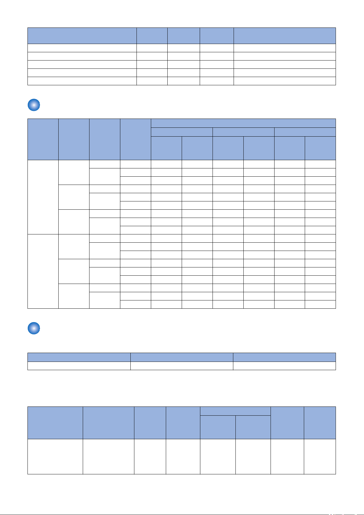
Productivity (Print speed)
Size Mode Paper type Paper ba-
sis weight
(g/m2)
Cassette Manual
2530 2525 2520
feed pick-
up tray
A4 1-sided Plain paper 64-90 30 30 25 25 20 20
Heavy Paper
2-sided
(with the 2
way unit)
2-sided
(without the
2 way unit)
A3 1-sided Plain paper 64-90 15 15 15 15 15 15
2-sided
(with the 2
way unit)
2-sided
(without the
2 way unit)
Plain paper 64-80 28 28 23 23 18 18
Heavy Paper
Plain paper 64-80 19 19 16 16 13 13
Heavy Paper
Heavy Paper
Plain paper 64-80 14 14 14 14 14 14
Heavy Paper
Plain paper 64-80 9 9 9 9 9 9
Heavy Paper
91-105 - 25 - 25 - 20
106-128 - 7 - 7 - 7
81-105 - - - - - -
106-128 - - - - - -
81-105 - - - - - -
106-128 - - - - - -
91-105 - 12 - 12 - 12
106-128 - 6 - 6 - 6
81-105 - - - - - -
106-128 - - - - - -
81-105 - - - - - -
106-128 - - - - - -
imageRUNNER
Cassette Manual
feed pick-
up tray
Cassette Manual
feed pick-
up tray
Paper type
For free size paper, refer to the table below.
Type Feeding direction (mm) Width direction (mm)
Free size 148 to 432 99 to 297
■ Pickup
Usable paper types are shown.
Paper type
(g/m2)
Plain (64 to 90)
Color (64 to 90)
Recycled (64 to 90)
Bond (75 to 90)
A4, A4R, A3, A5R,
B4, B5, B5R, LTR,
LTTR, LGL,
279mmX432mm
(11"X17"), STMTR
Size Manual
feed pick-
up tray
Yes Yes No Yes Yes Yes
Cassette 1 Cassette 2 Cassette 3 Cassette 4
with the en-
velope feed-
er
without the
envelope
feeder
13

1. Product Overview
Paper type
(g/m2)
Heavy Paper (91 to
128)
Labels A4, B4, LTR Yes No No No No No
Transparencies A4, LTR Yes No No No No No
3-hole punch LTR Yes Yes Yes Yes Yes Yes
Envelopes No.10 (COM10),
Free size 99 mm x 297 mm to
A4, A4R, A3, A5R,
B4, B5, B5R, LTR,
LTTR, LGL,
279mmX432mm
( 11"X17"), STMTR
ISO-B5, Monarch,
ISO-C5, DL
148 mm x 432 mm
Size Manual
feed pick-
up tray
Yes No No No No No
Yes No Yes No No No
Yes No No No No No
Cassette 1 Cassette 2 Cassette 3 Cassette 4
with the en-
velope feed-
er
without the
envelope
feeder
14
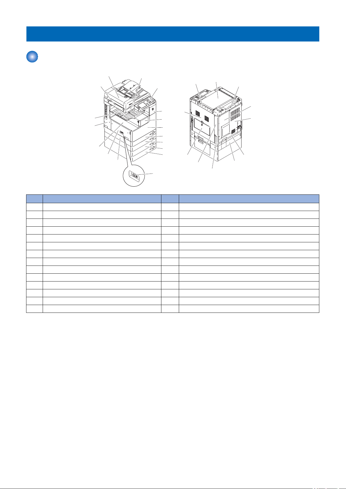
Name of Parts
[1]
[4]
[7]
[5]
[13]
[12]
[16]
[14]
[15]
[2]
[3]
[6]
[17]
[18]
[19]
[20]
[21]
[26]
[27]
[23]
[22]
[24]
[25]
[8]
[9]
[10]
[11]
[28]
External View
1. Product Overview
No. Part name No. Part name
[1] Reader left cover [15] Rear left cover
[2] DADF (standard or optional) [16] Toner supply cover
[3] Reader front cover [17] Reader right cover
[4] Control panel [18] Platen glass
[5] Support cover [19] Reader rear cover
[6] Delivery tray [20] Rear cover (right)
[7] Front cover [21] Rear cover (left)
[8] Cassette 1 [22] Right cover (upper rear)
[9] Cassette 2 (standard or optional) [23] Right cover (lower rear)
[10] Cassette 3 (option) [24] Manual feed pickup tray
[11] Cassette 4 (option) [25] Right cover
[12] Lower left cover [26] Lower rear cover
[13] Left cover [27] Cassette 2 rear cover
[14] Inside base cover [28] Main power switch
15
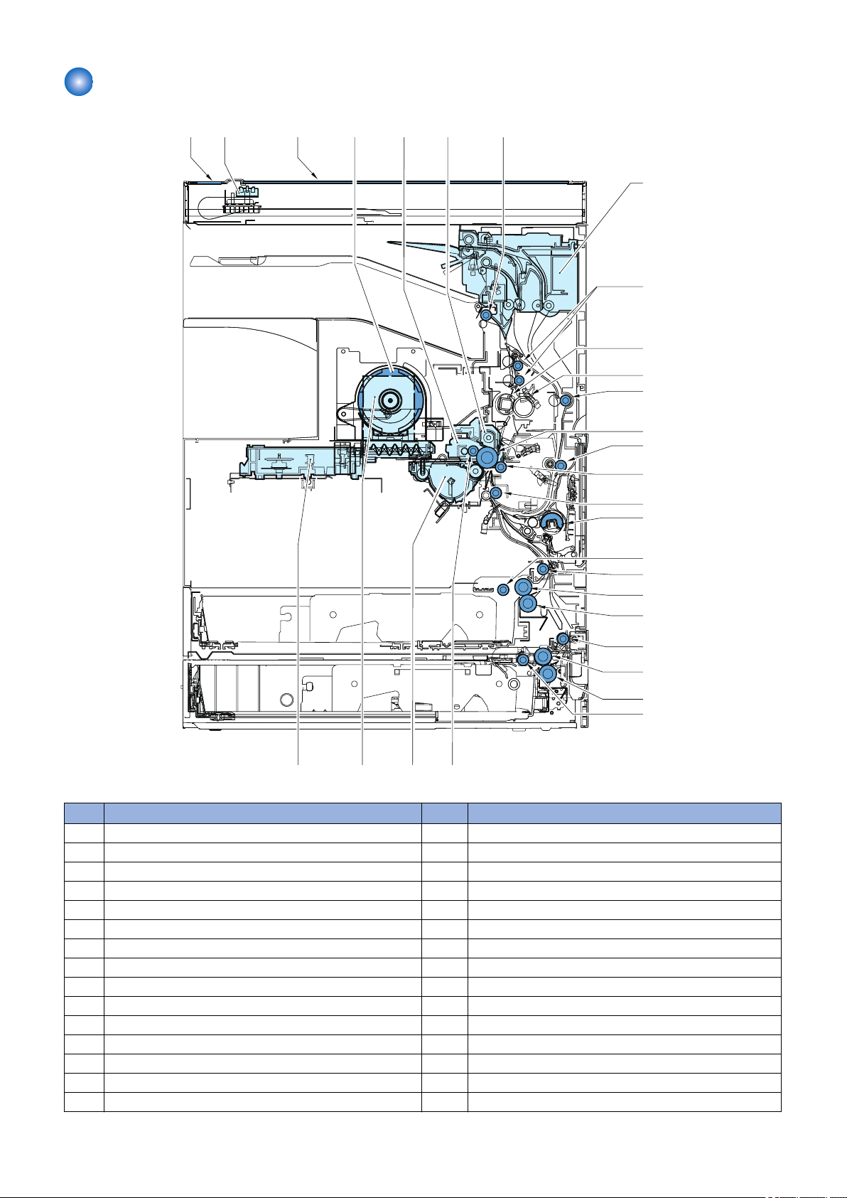
Cross Sectional View (550-sheet 1st cassete model)
[1] [2] [3] [4] [5] [6] [7]
[8]
[9]
[10]
[11]
[12]
[13]
[14]
[15]
[16]
[17]
[18]
[19]
[20]
[21]
[22]
[23]
[24]
[25]
[29] [28] [27] [26]
1. Product Overview
No. Part Name No. Part Name
[1] CIS unit [16] Registration roller
[2] ADF reading glass [17] Manual feed pickup roller
[3] Platen glass [18] Pickup roller (cassette 1)
[4] Toner bottle [19] Vertical path roller 1
[5] Drum unit [20] Feed roller (cassette 1)
[6] Drum cleaning unit [21] Separation roller (cassette 1)
[7] Delivery roller [22] Vertical path roller 2
[8] 2 way unit [23] Feed roller (cassette 2)
[9] Fixing outlet roller [24] Separation roller (cassette 2)
[10] Fixing film unit [25] Pickup roller (cassette 2)
[11] Pressure roller [26] Primary charging roller
[12] Duplex feed roller 1 [27] Developing unit
[13] Photosensitive drum [28] Sub hopper
[14] Duplex feed roller 2 [29] Laser scanner unit
[15] Transfer roller
16
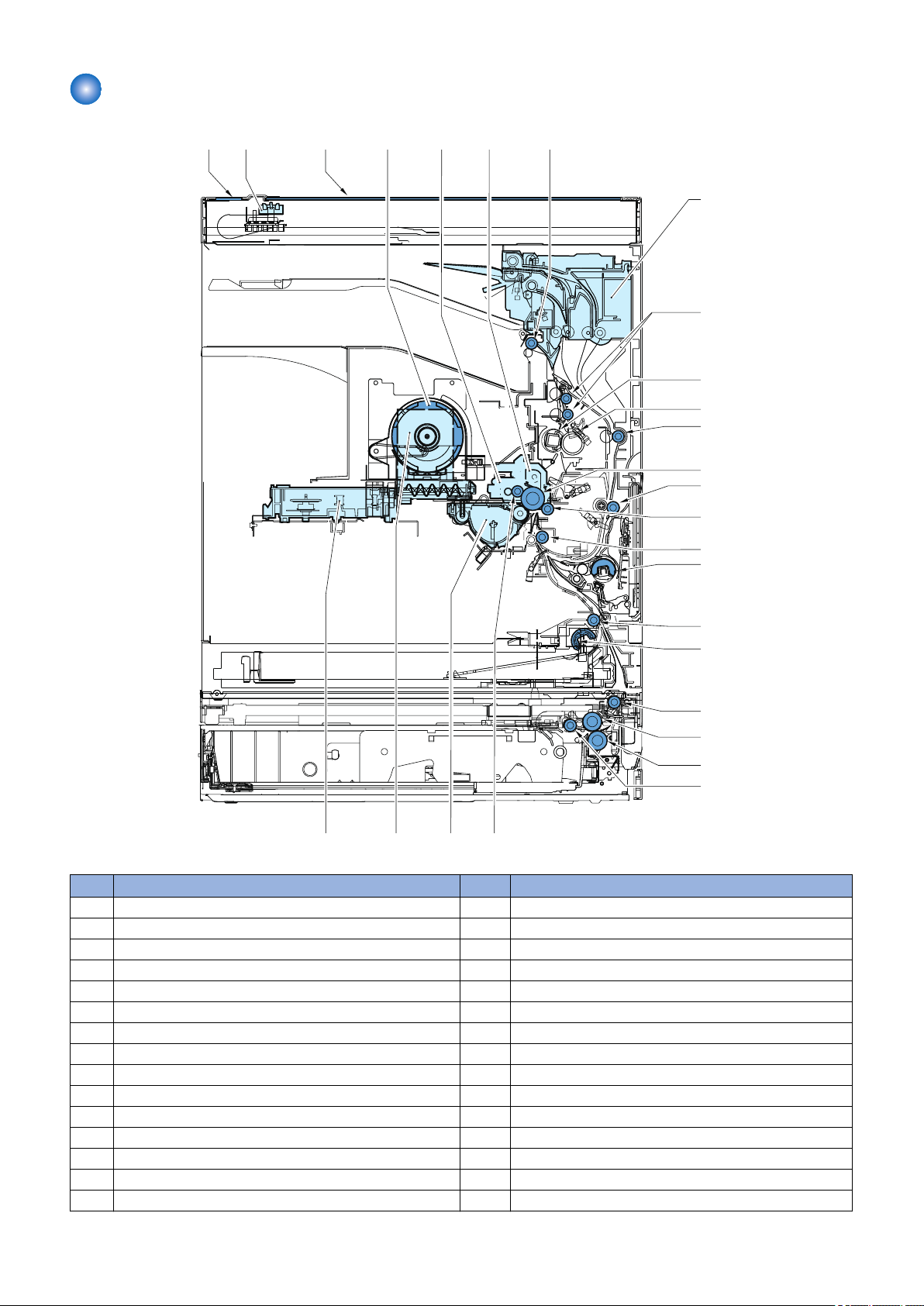
Cross Sectional View (250-sheet 1st cassette model)
[1] [2] [3] [4] [5] [6] [7]
[8]
[9]
[10]
[11]
[12]
[13]
[14]
[15]
[16]
[17]
[18]
[19]
[20]
[21]
[22]
[23]
[27] [26] [25] [24]
1. Product Overview
No. Part Name No. Part Name
[1] CIS unit [16] Registration roller
[2] ADF reading glass [17] Manual feed pickup roller
[3] Platen glass [18] Pickup roller (cassette 1)
[4] Toner bottle [19] Vertical path roller 1
[5] Drum unit [20] Vertical path roller 2
[6] Drum cleaning unit [21] Feed roller (cassette 2)
[7] Delivery roller [22] Separation roller (cassette 2)
[8] 2 way unit [23] Pickup roller (cassette 2)
[9] Fixing outlet roller [24] Primary charging roller
[10] Fixing film unit [25] Developing unit
[11] Pressure roller [26] Sub hopper
[12] Duplex feed roller 1 [27] Laser scanner unit
[13] Photosensitive drum
[14] Duplex feed roller 2
[15] Transfer roller
17
Operation
Main power switch
Control panel power switch
[1] [2] [3] [4] [5]
[6]
[7]
[8]
[9]
[10]
[11]
[12]
[15][16]
[13]
[14]
[17][18]
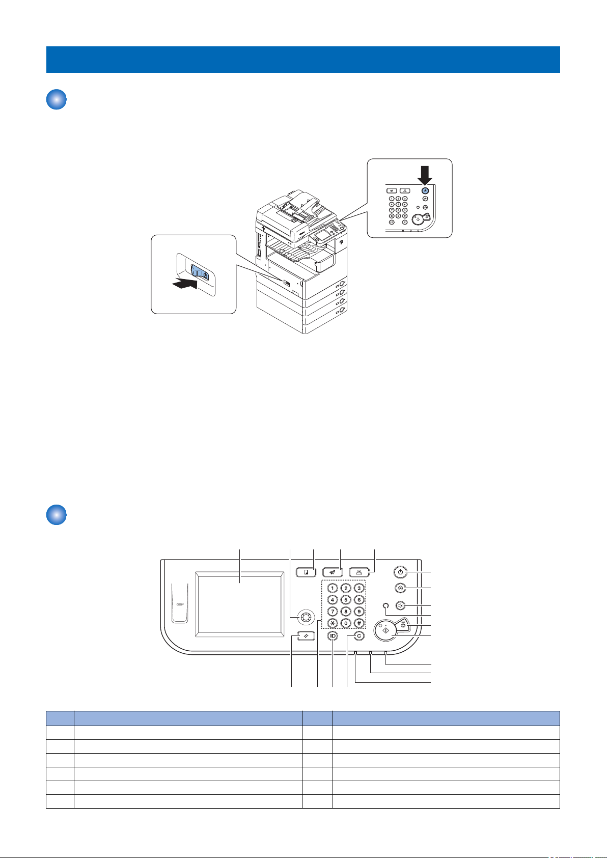
Power Switch
■ Types of power switch
1. Product Overview
This machine is equipped with the Main Power Switch and Control Panel Power Switch.
1. Main Power Switch
This switch is used to turn OFF / ON the power of host machine.
2. Control Panel Power Switch
This switch is to shift the machine to power-save mode or to restore it to normal mode.
■ How to turn ON / OFF the power and points to note
• To turn off the power, turn off the Main power Switch. (Conventional shutdown sequence operation is not required.)
• After power-off (After the Main power Switch is turned off), do not reactivate the Main power Switch until a screen disappears.
• do not turn off the power while download is processing.
Control Panel
No. Part name No. Part name
[1] Touch panel display [10] Stop key
[2] Display Contrast dial [11] Start key
[3] COPY key [12] Main Power Indicator
[4] SEND key [13] Error Indicator
[5] SCAN/OPTIONS key [14] Processing/Data Indicator
[6] Control Panel Power Switch (Sub Power Supply) [15] Clear key
18
No. Part name No. Part name
[6]
[7]
[8]
[9]
[1]
[2]
[3]
[4]
[5]
[7] Additional Function key [16] Log in/Out key
[8] Volume Control key [17] Numeric keys
[9] Counter Check key [18] Reset key
■ Main Menu
Functions Key Location
Copy COPY key Control Panel
Send or Fax SEND key
Remote Scan SCAN/OPTIONS key
System Monitor [System Monitor] Touch Panel Display
• The Send function is available only when the Color Send Kit-Y1 is activated.
• The Fax function is available only when the Super G3 Fax Board-AG1 is activated.
● Difference of main menu
imageRUNNER 2030/2025/2022/2018 Series imageRUNNER 2530/2525/2520 Series
Copy Copy
Send or Fax Send or Fax
Scan Scan or Direct print
System Monitor System Monitor
1. Product Overview
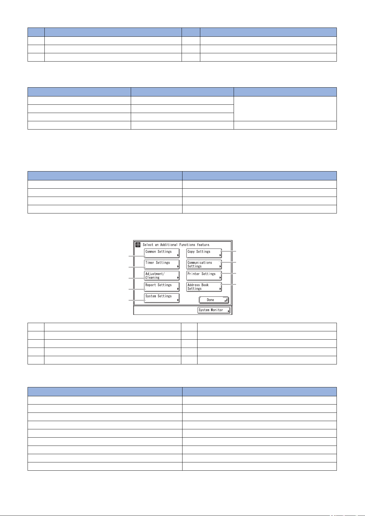
■ Settings / Registration menu
[1] Common Settings [6] Copy Settings
[2] Timer Settings [7] Communications Settings
[3] Adjustment/Cleaning [8] Printer Settings
[4] Report Settings [9] Address Book Settings
[5] System Settings
● Difference of Settings / Registration menu
imageRUNNER 2030/2025/2022/2018 Series imageRUNNER 2530/2525/2520 Series
Common Settings Common Settings
Timer Settings Timer Settings
Adjustment/Cleaning Adjustment/Cleaning
Report Settings Report Settings
System Settings System Settings
Copy Settings Copy Settings
Communications Settings Communications Settings
Printer Settings Printer Settings
Address Book Settings Address Book Settings
19

Technical
2
Explanation
Basic Configuration.............................21
Original Exposure System...................23
Controller System................................36
Laser Exposure System......................47
Image Formation System....................53
Fixing System......................................66
Pickup/Feed System........................... 76
Embedded RDS.................................. 97
 Loading...