

Image Reader-A1
iR5000i/iR6000i
REVISION 0
JUNE 2001
COPYRIGHT© 2001 CANON INC. CANON iR5000i/iR6000i REV.0 JUNE 2001 PRINTED IN JAPAN (IMPRIME AU JAPON)
FY8-13HH-000

Application
This manual has been issued by Canon Inc. for qualified persons to learn technical
theory, installation, maintenance, and repair of products. This manual covers all
localities where the products are sold. For this reason, there may be information in this
manual that does not apply to your locality.
Corrections
This manual may contain technical inaccuracies or typographical errors due to
improvements or changes in products. When changes occur in applicable products or in
the contents of this manual, Canon will release technical information as the need arises.
In the event of major changes in the contents of this manual over a long or short period,
Canon will issue a new edition of this manual.
The following paragraph does not apply to any countries where such provisions are
inconsistent with local law.
Trademarks
The product names and company names used in this manual are the registered
trademarks of the individual companies.
Copyright
This manual is copyrighted with all rights reserved. Under the copyright laws, this
manual may not be copied, reproduced or translated into another language, in whole or
in part, without the written consent of Canon Inc.
COPYRIGHT © 2001 CANON INC.
Printed in Japan
Imprimé au Japon
Caution
Use of this manual should be strictly supervised to avoid disclosure of confidential information.
COPYRIGHT© 2001 CANON INC. CANON iR5000i/iR6000i REV.0 JUNE 2001 PRINTED IN JAPAN (IMPRIME AU JAPON)
INTRODUCTION
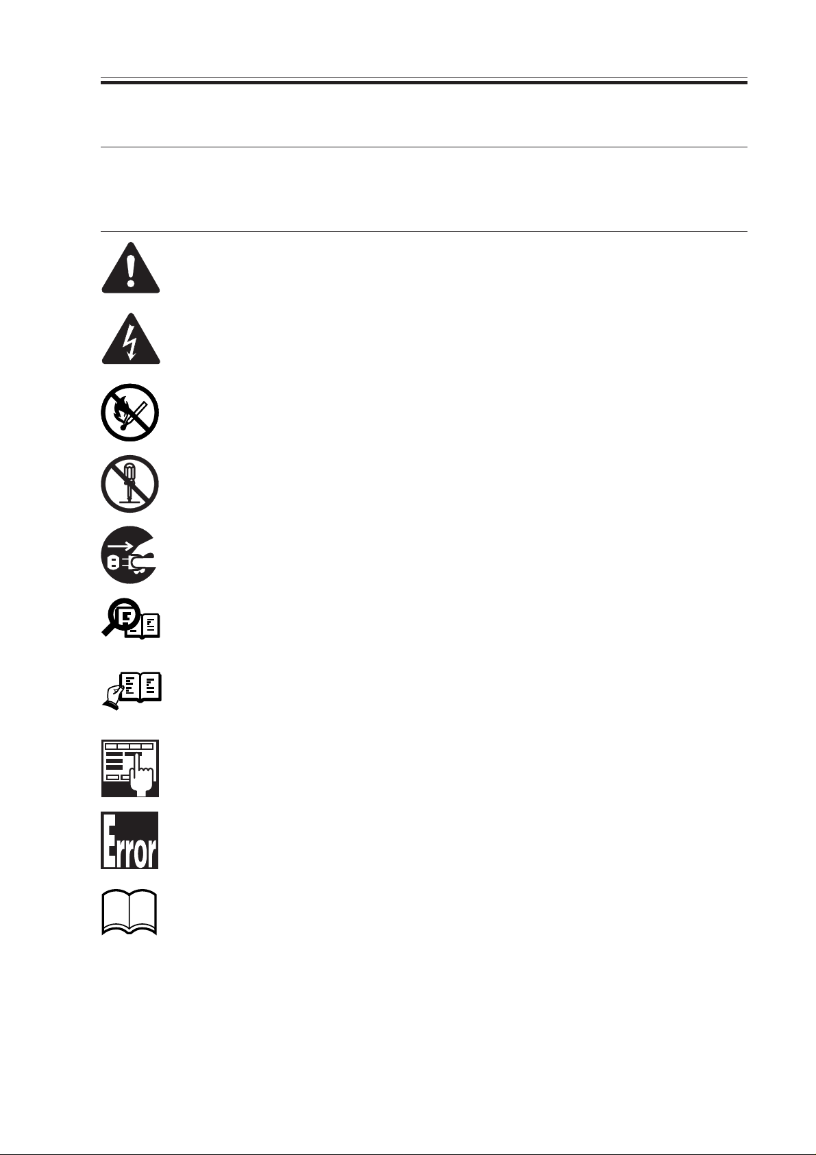
1.Symbols Used
This documentation uses the following symbols to indicate special information:
Symbol Description
Indicates an item of a non-specific nature, possibly classified as Note, Caution,
or Warning.
Indicates an item requiring care to avoid electric shocks.
Indicates an item requiring care to avoid combustion (fire).
Memo
REF.
Indicates an item prohibiting disassembly to avoid electric shocks or problems.
Indicates an item requiring disconnection of the power plug from the electric
outlet.
Indicates an item intended to provide notes assisting the understanding of the
topic in question.
Indicates an item of reference assisting the understanding of the topic in question.
Provides a description of a service mode.
Provides a description of the nature of an error indication.
COPYRIGHT
©
Refers to the Copier Basics Series for a better understanding of the contents.
2001 CANON INC. 2000 2000 2000 2000 CANON iR5000i/iR6000i REV.0 JUNE 2001
i

INTRODUCTION
2.Outline of the Manual
This Service Manual contains basic information needed to service the Image Reader-A1/
iR5000i/iR6000i and its accessories (i.e., side paper deck, shift tray) in the field, conducted
for the purpose of maintaining its product quality and a specific level of performance. A
separate Service Manual is made available for each of its accessories (except for the side paper deck and shift tray); for details, refer to the appropriate manual.
This Service Manual consists of the following chapters:
1. System Unit
Chapter 1 Introduction: features, specifications, names of parts, func-
tions, operation, system configuration, routine maintenance by the user
Chapter 2 Main Controller: functional construction, outline of electrical
circuitry, principles of operation of the image
processing system, power supply
Chapter 3 Installation: site conditions and installation procedure,
relocation of the machine, installation of accessories
2. Reader Unit
Chapter 1 Basic Operation: functional construction, outline of electrical
circuitry, basic sequence of operations
Chapter 2 Original Exposure System: principles of operation of the exposure sys-
tem, timing of operation, disassembly/assembly and adjustment
Chapter 3 Image Processing System: principles of operation of the image process-
ing system, timing of operation, disassembly/
assembly and adjustment
3. Printer Unit
Chapter 1 Introduction: safety of the laser, image formation, auxiliary
processes
Chapter 2 Sequence of Operations: basic operations, outline of electrical cir-
cuitry, basic sequence of operations
Chapter 3 Laser Exposure System: principles of operation of the laser exposure
system, timing of operation, disassembly/
assembly and adjustment
Chapter 4 Image Formation System: principles of operation of the image forma-
tion system, timing of operation, disassembly/assembly and adjustment
Chapter 5 Pickup/Feeding System: principles of operation of the pickup/feeding
system, timing of operation, disassembly/
assembly and adjustment
ii
COPYRIGHT
©
2001 CANON INC. 2000 2000 2000 2000 CANON iR5000i/iR6000i REV.0 JUNE 2001

INTRODUCTION
Chapter 6 Fixing System: principles of operation of the fixing system,
timing of operation, and disassembly/assembly and adjustment
Chapter 7 Externals and Controls: principles of operation of the externals/con-
trols, timing of operation, disassembly/assembly and adjustment
Chapter 8 Paper Deck: principles of operation, timing of operation,
disassembly/assembly and adjustment
Chapter 9 Shift Tray: principles of operation, timing of operation,
disassembly/assembly adjustment
4. Troubleshooting
Chapter 1 Maintenance and Inspection: table of periodically replaced parts, table of
consumables/durables, scheduled servicing
chart
Chapter 2 Image Adjustment Basic Procedure:
basic procedure for image adjustment
Chapter 3 Standards and Adjustments: standards and adjustments
Chapter 4 Troubleshooting Image Faults/Malfunctions:
troubleshooting image faults/malfunctions
Chapter 5 Service Mode: how to use service mode, list of service
modes
Chapter 6 Self Diagnosis: codes, causes of errors, timing chart
Appendix: general timing chart, general circuit diagrams
The descriptions are updated from time to time to reflect product improvements, and ma-
jor changes are communicated in the form of Service Information bulletins.
All service persons are expected to familiarize themselves with the contents of this Ser-
vice Manual and Service Information bulletins and acquire a level of knowledge and skill
required to promptly respond to the needs of the field.
COPYRIGHT
©
2001 CANON INC. 2000 2000 2000 2000 CANON iR5000i/iR6000i REV.0 JUNE 2001
iii

INTRODUCTION
The following rules apply throughout this Service Manual:
1. Each chapter contains sections explaining the purpose of specific functions and the relationship between electrical and mechanical systems with reference to the timing of
operation.
In the diagrams,
accompanies the symbol
represents the path of mechanical drive; where a signal name
, the arrow indicates the direction of the electric signal.
The expression “turn on the power” means flipping on the power switch, closing the
front cover, and closing the delivery unit cover, which results in supplying the machine
with power.
2. In the digital circuits, ‘1’ is used to indicate that the voltage level of a given signal is
“High,” while ‘0’ is used to indicate “Low.” (The voltage value, however, differs from
circuit to circuit.) In addition, the asterisk (*) as in “DRMD*” indicates that the
DRMD signal goes on when ‘0’.
In practically all cases, the internal mechanisms of a microprocessor cannot be
checked in the field. Therefore, the operations of the microprocessors used in the machines are not discussed: they are explained in terms of from sensors to the input of the
DC controller PCB and from the output of the DC controller PCB to the loads.
The descriptions in this Service Manual are subject to change without notice for product
improvement or other purposes, and major changes will be communicated in the form of
Service Information bulletins.
All service persons are expected to have a good understanding of the contents of this Service Manual and all relevant Service Information bulletins and be able to identify and isolate
faults in the machine.
iv
COPYRIGHT
©
2001 CANON INC. 2000 2000 2000 2000 CANON iR5000i/iR6000i REV.0 JUNE 2001
INTRODUCTION
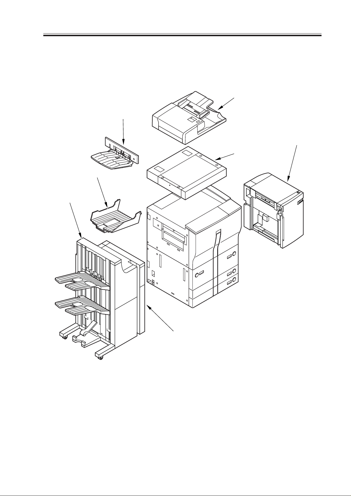
System Configuration
The iR5000i/iR6000i may be configured with the following accessories for a fully inte-
grated system:
[4]
[3]
[5]
[7]
[2]
[1]
[1] Finisher-F1/Saddle Finisher-F2
[2] Copy Tray-C1
[3] Shift Tray-B1
[4] DADF-D1 (standard)
[5] Paper Deck-G1
[6] Puncher Unit-B1/C1/D1
[7] Image Reader-A1
COPYRIGHT
©
2001 CANON INC. 2000 2000 2000 2000 CANON iR5000i/iR6000i REV.0 JUNE 2001
[6]
Figure 1
v
INTRODUCTION
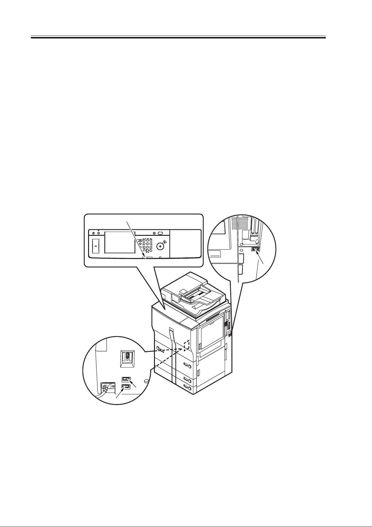
Important!
Be sure to turn off the main power switch and disconnect the power plug before starting
to disassemble the machine; in addition, keep the following in mind for the work:
1. In printer mode, turning off the main power switch can result in the loss of data being
processed. Check to make sure that the Execution/Memory lamp on the control panel
is off before operating the main power switch.
2. Do not turn off the main power switch while downloading is taking place. Otherwise,
the machine may become disabled.
3. The cassette heater and the drum heater remain powered as long as the environment
switch and the heater switch are on (even when the main power switch is off).
4. Not all power is removed when the front cover is opened if the main power switch is
on, requiring care.
[1]
Counter
Check
Display Contrast
Additional Function
Reset
Guide
123
456
789
ID
Processing
/Data
0C
Error
Energy Save
ON/OFF
Stop
Start
Clear
Power
[2]
[3]
[4]
[1] Execution/Memory lamp
[2] Main power switch
[3] Cassette heater switch
[4] Environment switch
Figure 2 Arrangement of the Switches
vi
COPYRIGHT
©
2001 CANON INC. 2000 2000 2000 2000 CANON iR5000i/iR6000i REV.0 JUNE 2001
SYSTEM UNIT
COPYRIGHT
©
2001 CANON INC. 2000 2000 2000 2000 CANON iR5000i/iR6000i REV.0 JUNE 2001


Contents
CHAPTER 1 GENERAL DESCRIPTION
CONTENTS
1. Features ..........................................1-1S
1.1.1 High Speed, High Image
Quality ...............................1-1S
1.1.2 Hard Disk ..........................1-1S
1.1.3 Stackless, Duplexing
Mechanism .........................1-1S
1.1.4 Large-Capacity Paper
Source ................................1-1S
1.1.5 Variety of Delivery Processing
(with accessories) ..............1-1S
1.1.6 Printer Type .......................1-1S
1.1.7 Addition of the Differential
PCB....................................1-1S
2. Specifications .................................1-2S
2.1 Copier....................................... 1-2S
2.1.1 Type ...................................1-2S
2.1.2 Method ...............................1-2S
2.1.3 Functions ...........................1-3S
2.1.4 Others ................................1-8S
2.2 Paper Deck-G1....................... 1-11S
2.3 Shift Tray-B1 .........................1-12S
3. Names of Parts .............................1-13S
3.1 External V i e w.........................1-13S
3.2 Cross Section (Printer unit) ...1-15S
3.3 Cross Section (Reader unit) ...1-17S
4. Using the Machine .......................1-19S
4.1 Turning On the Power
Switches .................................1-19S
4.2 Control Panel ..........................1-20S
4.3 Extension Mode .....................1-21S
4.4 User Mode .............................1-22S
5. System Construction.....................1-26S
5.1 Functional Construction .........1-26S
5.2 Outline of Electrical Circuitry .1-27S
5.2.1 Construction of Electrical
Circuitry...........................1-27S
5.3 Inputs to and Outputs from
the Major PCBs......................1-28S
5.3.1 Wiring Diagram of the
Major PCBs .....................1-28S
6. Routine Maintenance by the User .1-29S
6.1 Cleaning .................................1-29S
6.2 Inspection ...............................1-32S
6.2.1 Making a Check ...............1-32S
CHAPTER 2 MAIN CONTROLLER
1. Basic Operations ............................2-1S
1.1 Functional Construction .......... 2-1S
1.2 Outline of Electrical Circuitry .2-2S
1.2.1 Outline ...............................2-2S
1.2.2 Main Controller PCB ......... 2-2S
1.2.3 Hard Disk Drive.................2-2S
1.3 Start-Up Sequence ...................2-4S
1.3.1 Outline ...............................2-4S
1.3.2 Start-Up Sequence .............2-5S
1.4 Inputs to and Outputs from
the Major PCBs........................2-7S
COPYRIGHT
©
2001 CANON INC. 2000 2000 2000 2000 CANON iR5000i/iR6000i REV.0 JUNE 2001
1.4.1 Wiring Diagram of the
2. Digital Image Processing ................2-8S
2.1 Outline ......................................2-8S
2.2 Input Image Processing ............2-9S
2.2.1 Image Data from the
2.2.2 Enlargement/Reduction
2.2.3 Edge Emphasis...................2-9S
2.2.4 Editing ................................2-9S
2.2.5 Density Conversion (LUT) 2-9S
Major PCBs .......................2-7S
Reader Unit ........................2-9S
(main scanning direction) ...2-9S
S1

CONTENTS
2.2.6 Binary Processing (error
diffusion; T-BIC) ............... 2-9S
2.2.7 Binary Processing (dither
screen)..............................2-10S
2.3 Controlling the Image
Memory ..................................2-11S
2.3.1 Compression/Decompression,
Rotation, Enlargement/
Reduction .........................2-11S
2.3.2 SDRAM ..........................2-11S
2.3.3 Hard Disk Drive (HDD)..2-11S
2.4 Output Image Processing .......2-11S
2.4.1 Smoothing........................2-11S
2.4.2 Thickening
(PDL output only) ............2-11S
2.4.3 Binary-Binary Density
Conversion (read image
output only) ......................2-11S
3. Flow of Image Data ......................2-12S
3.1 Flow of Image Data During
Copying..................................2-12S
3.1.1 Local Copying..................2-12S
3.1.2 Remote Copying ..............2-13S
3.1.3 Tandem Copying ..............2-14S
3.2 Transmission ..........................2-15S
3.2.1 Outline..............................2-15S
3.2.2 Flow of Image Data
(during transmission)....... 2-16S
3.3 Print........................................2-17S
3.3.1 Flow of Print Jobs ............2-17S
3.3.2 TCP/IP..............................2-18S
3.3.3 NetWare............................2-19S
3.3.4 AppleTalk .........................2-20S
3.3.5 Processing Print Data .......2-21S
4. Soft Counter ................................. 2-22S
5. Controlling the Power Supply......2-24S
5.1 Outline ................................... 2-24S
5.2 Power Supply Mode .............. 2-24S
5.3 Standby Mode
(normal operation) ..................2-24S
5.4 Power Save Mode ..................2-24S
5.5 Low Power Mode ..................2-25S
5.5.1 Shift from Standby Mode
(standby → low-
power) ..............................2-25S
5.5.2 Shift to Standby Mode
(low power → standby) ...2-25S
5.6 Sleep Mode ............................2-25S
5.6.1 Shift from Standby Mode
(standby → sleep)............2-25S
5.6.2 Shift from Low Power Mode
(low power
mode → sleep) .................2-25S
5.6.3 Return to Standby Mode
(sleep → standby) ............2-25S
5.7 Off Mode................................2-26S
5.7.1 Shift from Standby Mode
(standby → off mode) .....2-26S
5.7.2 Shift from Low Power
Mode (low power
mode → off mode)...........2-26S
5.7.3 Return to Standby Mode
(off mode → standby) ....2-26S
5.8 Power Off Mode ....................2-26S
6 User Software...............................2-27S
6.1 Outline ................................... 2-27S
6.2 Printer Drivers........................2-27S
6.3 Utilities...................................2-27S
6.3.1 Netspot .............................2-27S
6.3.2 JBIG Viewer .....................2-27S
6.3.3 Network ScanGear
(Windows only) ...............2-27S
S2
COPYRIGHT
©
2001 CANON INC. 2000 2000 2000 2000 CANON iR5000i/iR6000i REV.0 JUNE 2001

CHAPTER 3 INSTALLATION
CONTENTS
1. Selecting the Site............................3-1S
2. Unpacking and Installation ............3-3S
2.1 Before Starting the Work .........3-3S
2.2 Installation ...............................3-4S
2.3 Unpacking................................3-5S
2.4 Installing the Image
Reader-A1 ................................ 3-7S
2.5 Mounting the Fixing
Assembly ...............................3-12S
2.6 Checking the Charging
Assemblies .............................3-14S
2.7 Mounting the Developing
Assembly ...............................3-17S
2.8 Mounting the Pickup
Assembly ...............................3-18S
2.9 Mounting the Deck Locking
Plate (left deck) .......................3-19S
2.10 Supplying Toner .....................3-20S
2.11 Setting the Cassette .................3-21S
2.12 Changing the Paper Size for the
Front Deck (right/left) ............3-22S
2.13 Installing the DADF-D1 ........3-22S
2.14 Checking Images/Operations
and User Mode .......................3-23S
2.15 Checking the Environment
Switch ....................................3-25S
2.16 Installing the Machine ............3-26S
2.17 Connecting to the Network .....3-26S
2.18 Checking the Connection to
the Network ............................3-27S
2.19 Troubleshooting the
Network .................................3-28S
3. Relocating the Machine .................3-29S
4. Mounting the Delivery Tray .........3-30S
5. Mounting the Original Holder ......3-32S
6. Installing the Card
Reader-C1 (option) .......................3-33S
7. Installing the NE
Controller-A1 ............................... 3-34S
7.1 Installation ..............................3-34S
COPYRIGHT
©
2001 CANON INC. 2000 2000 2000 2000 CANON iR5000i/iR6000i REV.0 JUNE 2001
S3


CHAPTER 1
GENERAL DESCRIPTION
COPYRIGHT
©
2001 CANON INC. 2000 2000 2000 2000 CANON iR5000i/iR6000i REV.0 JUNE 2001


CHAPTER 1 GENERAL DESCRIPTION
1.Features
1.1.1 High Speed, High Image Quality
Copying speed: 50 copies/min (iR5000i; 1-on-N; from cassette/deck)
60 copies/min (iR6000i; 1-on-N; from cassette/deck)
Reading resolution: 600 × 600 dpi
Printing resolution: 1200* × 600 dpi (copier mode; smoothing ON; varies by model)
2400* × 600 dpi (printer mode)
*Equivalent.
1.1.2 Hard Disk
The machine comes with a hard disk as standard, enabling memory-based sorting. The
machine is capable of making multiple copies by reading the original once.
1.1.3 Stackless , Duplexing Mechanism
The machine moves paper seamlessly when making double-sided copies without any
waste as by stacking it in a duplexing unit.
1.1.4 Large-Capacity Paper Source
The addition of an accessory will enable accommodation of as many as 7650 sheets of pa-
per (80 g/m
2
).
Right front paper deck: 1500 sheets
Left front paper deck: 1500 sheets
2
Cassette 3: 550 sheets (if 64 g/m
Cassette 4: 550 sheets (if 64 g/m
, 600 sheets)
2
, 600 sheets)
Multifeeder: 50 sheets
Paper Deck-G1 (accessory): 3500 sheets
1.1.5 Variety of Delivery Processing (with accessories)
Finishing: 1-point or 2-point stapling (Finisher)
Saddle stitching: middle binding and folding for delivery (Saddle Finisher-F2 only)
Punching: making binding holes for delivery (Puncher Unit)
1.1.6 Printer T ype
The machine possesses printer functions from the printer mechanisms of the iR5000/
6000; when combined with the Image Reader-A1, it provides functions expected of conventional copiers.
1.1.7 Addition of the Diff erential PCB
The differential PCB is an addition provided to send signals from the image reader to the
main controller of the machine.
COPYRIGHT
©
2001 CANON INC. 2000 2000 2000 2000 CANON iR5000i/iR6000i REV.0 JUNE 2001
1-1 S

CHAPTER 1 GENERAL DESCRIPTION
2. Specifications
2.1 Copier
2.1.1 Type
Item
Body
Copyboard
Light source
Lens
Photosensitive medium
2.1.2 Method
Item
Reproduction
Charging
Exposure
Copy density adjustment
Development
Pickup
Transfer
Separation
Cleaning
Fixing
Specifications
Separate reader/printer
Fixed
Xenon tube
Lens array (F3.7)
Amorphous silicon drum (80-dia.)
T01-201-01
Specifications
Indirect statophotography
Corona
Laser
Auto or manual
Dry, 1-component toner production
Auto
Front paper deck (2 holders)
Front cassette (2 holders)
Manual
Manual feed tray
(5.5 mm deep; about 50 sheets of 80 m
Corona
Corona (static separation)
Blade
Heat roller
100 V: 700 W (main) + 470 W (sub)
120/230 V: 600 W (main) + 600 W (sub)
2
paper)
1-2 S
COPYRIGHT
©
T01-201-02
2001 CANON INC. 2000 2000 2000 2000 CANON iR5000i/iR6000i REV.0 JUNE 2001

2.1.3 Functions
CHAPTER 1 GENERAL DESCRIPTION
Item
Original type
Maximum original size
Reproduction ratio
Wait time
First copy time
Continuous reproduction
Print size
Specifications
Sheet, book, 3-D object (2 kg max.)
A3/279.4×431.8 mm (11"×17")
Direct 1: 1
Reduce I 1: 0.250
Reduce II 1: 0.500
Reduce III 1: 0.611
Reduce IV 1: 0.707
Reduce V 1: 0.816
Reduce IV 1: 0.865
Enlarge I 1: 0.154
Enlarge II 1 : 1.224
Enlarge III 1: 0.414
Enlarge IV 1: 2.000
Enlarge V 1: 4.000
Zoom 1: 0.250 to 4.00 (in 1% increments)
iR5000i: 5 min or less (at 20°C/168°F)
iR6000i: 6 min or less (at 20°C/168°F)
5.1sec (stream reading, right deck, Direct, A4/LTR,
non-AE, straight delivery)
3.8 sec (book mode, right deck pickup, Direct, A4/LTR,
non-AE, straight delivery)
999 prints max.
Single-sided
Duplexing
AB
Inch
AB
Inch
A3 max.
279.4 × 431.8 mm
(11"×17") max.
A3 max.
279.4 × 431.8 mm
(11"×17") max.
Postcard min.
(vertical)
STMT min.
(vertical)
A5 min.
(vertical)
STMT min.
(vertical)
COPYRIGHT
©
T-01-201-03
2001 CANON INC. 2000 2000 2000 2000 CANON iR5000i/iR6000i REV.0 JUNE 2001
1-3 S

CHAPTER 1 GENERAL DESCRIPTION
Pickup
Right deck
Left deck
Cassette 3
Cassette 4
Manual feed tray
Paper type
Plain paper (64 to 80 g/m
2
)
A4, B5, LTR
Tracing paper
A4, B5
Colored paper (Canon-recommended)
A4
Thick paper (90 to 200 g/m
2
)
A4, B5, LTR
Plain paper (64 to 80 g/m
2
)
A3, B4, A4, B5, A5R, A4R, B5R
279.4×431.8 mm (11" × 17"), LGL, LTR, LTRR, STMT
(vertical feeding)
Tracing paper
B4, A4, A4R
Colored paper (Canon-recommended)
(vertical feeding) (64 to 80 g/m
2
)
A3, B4, A4, B5, A5R, A4R, B5R
279.4×431.8 mm (11" × 17"), LGL, LTR, LTRR, STMT (vertical feeding)
Tracing paper
A3, B4, A4, B5, A4R, B5R
Transparency (Canon-recommended)
A4, A4R, LTR, LTRR
Colored paper (Canon-recommended)
B4, A4, A4R
Postcard (vertical feeding only)
Postcard, 2-in-1 postcard (vertical feeding only),
4-in-1 postcard (horizontal feeding only)
Label sheet (Canon-recommended)
B4, A4, A4R, LTR, LTRR
Thick paper (90 to 200 g/m
2
)
A3, B4, A4, B5, A4R, B5R, LTR, LTRR
1-4 S
COPYRIGHT
©
T-01-201-04
2001 CANON INC. 2000 2000 2000 2000 CANON iR5000i/iR6000i REV.0 JUNE 2001

CHAPTER 1 GENERAL DESCRIPTION
Item
Single-sided
Reverse delivery
Paper type
Plain paper (64 to 80 g/m
2
)
A3, B4, A4, B5, A5R, A4R, B5R
279.4×431.5 mm (11"×17"), LGL, LTR, LTRR, STMT
(vertical feeding)
Tracing paper
A3, B4, A4, B5, A4R, B5R
Transparency (Canon-recommedned)
A4, A4R, LTR, LTRR
Colored paper (Canon-recommended)
B4, A4, A4R
Postcard (vertical feeding only)
Postcard, 2-in-1 postcard (vertical feeding only),
4-in-1 postcard (horizontal feeding only)
Label sheet (Canon-recommended)
B4, A4, A4R, LTR, LTRR
Thick, paper (90 to 200 g/m
2
)
A3, B4, A4, B5, A4R, B5R, LTR, LTRR
Plain paper (64 to 80 g/m
2
)
A3, B4, A4, B5, A5R, A4R, B5R
279.4×431.8 mm (11"×17"), LGL, LTR, LTRR, STMT (vertical feeding)
Colored paper (Canon-recommended)
B4, A4, A4R
Thick paper (90 to 200 g/m
2
)
A3, B4, A4, B5, A4R, B5R, LTR, LTRR
COPYRIGHT
©
T01-201-05
2001 CANON INC. 2000 2000 2000 2000 CANON iR5000i/iR6000i REV.0 JUNE 2001
1-5 S

CHAPTER 1 GENERAL DESCRIPTION
Double-sided
Item
Auto
Manual feed tray
Paper type
• Plain paper (64 to 80 g/m
2
)
A3, B4, A4, B5, A5R, A4R , B5R
279.4×431.8 mm (11"×17"), LGL, LTR, LTRR,
STMT (vertical feeding)
• Colored paper (Canon-recommended)
B4, A4, A4R
Thick paper (90 to 200 g/m
2
)
A3, B4, A4, B5, A4R, B5R, LTR, LTRR
• Plain paper (64 to 80 g/m
2
)
A3, B4, A4, B5, A5R, A4R, B5R
279.4×431.8 mm (11"×17"), LGL, LTR, LTRR,
STMT (vertical feeding)
• Colored paper (Canon-recommended)
B4, A4, A4R
• Thick paper (90 to 200 g/m
2
)
A3, B4, A4, B5, A4R, B5R, LTR, LTRR
T01-201-06
1-6 S
COPYRIGHT
©
2001 CANON INC. 2000 2000 2000 2000 CANON iR5000i/iR6000i REV.0 JUNE 2001

CHAPTER 1 GENERAL DESCRIPTION
Item
Claw
Tray
Paper deck
(right, left)
Cassette 3/4
Delivery tray
Hard disk
Non-image
width
Leading edge
Trailing edge
Left/right (1st side)
Auto clear
Auto power off
Low-power mode
Power save
Auto sleep
mode
Energy save mode
Accessories
Specifications
None
162 mm/16.4 in deep (approx.; about 1500 sheets of 80 g/
2
m
paper)
55 mm/2.2 in deep (approx.; about 550 sheets of 80 g/m
2
250 sheets (approx.; of 80 g/m
)
2
)
10GB*1
Direct/Enlarge-Reduce: 4.0 ± 1.5/-1.0mm < 4.5 ± 1.8mm >*2
Direct/Enlarge-Reduce: 2.5 ± 1.5mm < 2.0 ± 1.8 mm >*2
Direct/Enlarge-Reduce: 2.5 ± 1.5mm < 2.5 ± 2.0 mm >*2
Yes (2 min standard; may be changed between 0 and
9 min in 1-min increments)
No
Yes (15 min standard; may be changed in user mode
for 10, 15, 20, 30, 40, 50, 60, 90 min and 2, 3, 4 hr)
Yes (60 min standard; may be changed to 10, 15, 20, 30, 40,
50, 60, 90 min, 2, 3, 4 hr in user mode)
Yes (-10% standard; may be changed to -10%, -25%,
-50%, no return time (0%) in user mode)
• Paper Deck-G1
• Remote Diagnostic Device II
• Control Card-IV
• Finisher-F1
• Saddle Finisher-F2
• Puncher Unit-B1/C1/D1 (2/3/4 holes)
• Network LIPS Printer Kit-A1 (100V only)
• Network Multi-PDL Printerkit-A1 (120/230V only)
*1: The HDD mounted in the machine or an HDD supplied as a service part may have a dif-
ferent memory size; all HDDs use the same area (amount) of memory and, therefore, the
fact will not cause a problem.
*2: The values within <> indicate the use of an ADF.
T01-201-07
The specifications are subject to change for product improvement.
COPYRIGHT
©
2001 CANON INC. 2000 2000 2000 2000 CANON iR5000i/iR6000i REV.0 JUNE 2001
1-7 S

CHAPTER 1 GENERAL DESCRIPTION
2.1.4 Others
Item
Operating
environment
Temperature
Humidity
Atmospheric
pressure
Power supply
100V (50/60Hz)
120V (50/60Hz)
230V (50/60Hz)
AB size
Inch/A size
A size
Inch/AB size
Power
consumption
Maximum
Stand by
Noise
Continuous
copying
During copying
During standby
Ozone (after 250, 000 prints)
Width
Dimensions
Depth
Height
Weight
Consumables
Paper
Toner
(Magnetic nega-
tive)
Specifications
15 to 30°C/59 to 86°F
5% to 80%RH
810.6 to 1013.3 hpa (0.8 to 1.0 atm)
iR5000i iR6000i
LLXxxxxx LLZxxxxx
NRLxxxxx NRQxxxxx
NRMxxxxx NRSxxxxx
PPGxxxxx PPTxxxxx
PPRxxxxx PPUxxxxx
QCYxxxxx QDDxxxxx
RDCxxxxx RDHxxxxx
SCMxxxxx SCNxxxxx
TCNxxxxx TCTxxxxx
UFUxxxxx UFVxxxxx
Image Reader-A1
XCWxxxxx
XCXxxxxx
XCYxxxxx
XCZxxxxx
iR5000i: 1.5 kW or less iR6000i: 1.5 kW or less
iR5000i: 262 Wh iR6000i: 282 Wh
(approx.; reference) (approx.; reference)
iR5000i: 979 Wh (approx.; reference only)
iR6000i: 1008 Wh (approx.; reference only)
By sound power level (impulse mode)
iR5000i: 71 dB or less iR6000i: 78 dB or less
iR5000i: 50 dB or less iR6000i: 55 dB or less
0.05 ppm or less (Average)
643 mm/25.3 in
743 mm/29.3 in
1136 mm/44.7 in
210 kg (approx.)/470.4 lb (approx.)
Keep wrapped, and store avoiding humidity.
Avoid direct sunlight, and store at 40°C,
85% RH or less.
1-8 S
COPYRIGHT
©
T01-201-08
2001 CANON INC. 2000 2000 2000 2000 CANON iR5000i/iR6000i REV.0 JUNE 2001

CHAPTER 1 GENERAL DESCRIPTION
Reproduction ratio
Direct
Reduce II
(50%)
III
(61.1%)
IV
(70.7%)
V
(81.6%)
VI
(86.5%)
Size
A3 (297×420 mm)
A4 (210×297 mm)
B4 (257×364 mm)
B5 (182×257 mm)
A4R (297×210 mm)
B5R (257×182 mm)
A5R (210×149 mm)
A3→A5R
A3→B5R
B4→B5R
A3→A4R
B4→A4R
B5R→A5R
A4→B5
A3→B4
Paper size
A3
A4
B4
B5
A4R
B5R
A5R
A5R
B5R
B5R
A4R
A4R
A5R
B5
B4
copies/min (1-to-N)
iR5000i iR6000i
30 30
50 60
36 36
50 60
38 41
40 44
50 60
50 60
40 44
40 44
38 41
38 41
50 60
50 60
36 36
Enlarge IV
A5R→A3
A3
30 30
(200.0%)
III
(141%)
II
(122.4%)
I
(115.4%)
A4R→A3
B5R→B4
A4R→B4
A5→B5
B4→A3
B5→A4
A3
B4
B4
B5
A3
A4
30 30
36 36
36 36
50 60
30 30
50 60
Delivery by the machine, auto paper select, auto density select, non-sort, deck/cassette
T01-201-09 Copying Speeds (copier only)
COPYRIGHT
©
2001 CANON INC. 2000 2000 2000 2000 CANON iR5000i/iR6000i REV.0 JUNE 2001
1-9 S

CHAPTER 1 GENERAL DESCRIPTION
Reproduction ratio
Direct
Reduce II
(50.0%)
III
(64.7%)
IV
(73.3%)
V
(78.6%)
Enlarge IV
(200.0%)
III
(129.4%)
II
(121.4%)
Size
279.4×431.8 mm
(11"×17")
LTR
LGL
LTRR
STMTR
279.4×431.8 mm
(11"×17")→STMTR
279.4×431.8 mm
(11"×17")→LTRR
279.4×431.8 mm
(11"×17")→LGL
LGL→LTRR
STMTR*→
279.4×431.8 mm
(11"×17")
LTRR →
279.4×431.8 mm
(11"×17")
LGL→
279.4×431.8 mm
(11"×17")
Paper size
279.4×431.8 mm
(11"×17")
LTR
LGL
LTRR
STMTR
STMTR
LTRR
LGL
LTRR
279.4×431.8 mm
(11"×17")
279.4×431.8 mm
(11"×17")
279.4×431.8 mm
(11"×17")
copies/min
iR5000i iR6000i
30 30
50 60
36 36
39 42
50 60
50 60
39 42
36 36
39 42
30 30
30 30
30 30
* Cannot be set in an ADF as an original.
Delivery by the machine, auto paper select, auto density select, non-sort, deck/cassette
T01-201-10 Copying Speeds (copier only)
The specifications are subject to change for product improvement.
1-10 S
COPYRIGHT
©
2001 CANON INC. 2000 2000 2000 2000 CANON iR5000i/iR6000i REV.0 JUNE 2001

2.2 Paper Deck-G1
CHAPTER 1 GENERAL DESCRIPTION
Item
Pickup
Paper accommodation
Paper type
Paper stack
Serial number
Paper size switch
Dimensions
Weight
Power supply
Operating environment
Temperature
Humidity
Atmospheric pressure
Specifications
Clawless (retard)
Side tray
2
• Plain paper (64 to 80 g/m
)
A4, B5, LTR
• Tracing paper (SM-1)
A4, B5
• Colored paper (Canon-recommended)
A4
Thick paper (90 to 200 g/m
2
)
A4, B5, LTR
Height: 385 mm (approx.; about 3500 sheets)
A4 type: XCQ xxxxx/LTR type: XCRxxxxx
By size guide plate (in steps),
in service mode (OPTION)
326.2 (W) × 583 (D) × 574.5 (H) mm/
12.8 (W) × 23.0 (D) × 22.6 (H) in
46 kg (approx.)/101.4 lb (approx.)
DC from host machine
Same as host machine
T01-202-01
The specifications are subject to change for product improvement.
COPYRIGHT
©
2001 CANON INC. 2000 2000 2000 2000 CANON iR5000i/iR6000i REV.0 JUNE 2001
1-11 S

CHAPTER 1 GENERAL DESCRIPTION
2.3 Shift Tra y-B1
Item
Paper type
Paper size
Feeding
Shifting
Paper stack
Stacking performance
Delivery direction
(w/ shift)
Shift direction
(w/ shift)
w/o shift
Serial number
Dimensions (shift tray alone)
Weight
Power supply
Maximum power consumption
Operating environment
Temperature
Humidity
Atmospheric pressure
Specifications
Same as host machine
Same as host machine
LTR, LTRR, LGL, 279.4×431.8 mm (11"×17"),
A4, A4R, A3
Height: 60 mm /2.4 in
2
(approx.; about 500 sheets of 64 g/m
)
50 mm or less
between stacks: 20 mm or more
within stack: [between stacks -5] mm
100 mm or less
XCSxxxxx
365.3 (W) × 547.0 (D), 255.7 (H) mm/
14.4 (W) × 21.5 (D) × 10.1 (H) in
4.2 kg (approx.)/9.3 lb (approx.)
DC from host machine
2 W or less
(15 W or less when connected to host)
Same as host machine
T01-203-01
The specifications are subject to change for product improvement.
1-12 S
COPYRIGHT
©
2001 CANON INC. 2000 2000 2000 2000 CANON iR5000i/iR6000i REV.0 JUNE 2001
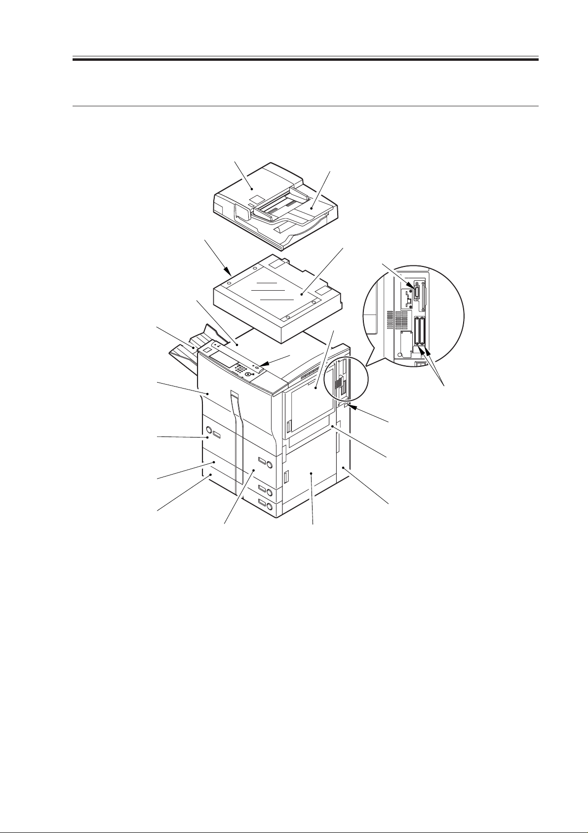
3.Names of Par ts
3.1 External View
[18]
[17]
CHAPTER 1 GENERAL DESCRIPTION
[1]
[3]
[19]
[14]
[13]
[12]
[9]
[10]
[11]
[1] ADF
[2] Main power switch
[3] Original pickup tray
[4] Manual feed tray
[5] Right upper cover
[6] Right lower cover
[7] Waste toner box, grip,
drum protection sheet case
[8] Right front paper deck
[9] Left front paper deck
[4]
[16]
[8]
[6]
[10] Cassette 3
[11] Cassette 4
[12] Front cover
[13] Delivery tray
[14] Parallel connector for downloading
[15] Slot for expansion board
[16] Control panel power switch
[17] Top panel
[18] Reader Unit (Image Reader-A1)
[19] Copyboard glass
[15]
[2]
[5]
[7]
COPYRIGHT
©
F01-301-01 External View 1
2001 CANON INC. 2000 2000 2000 2000 CANON iR5000i/iR6000i REV.0 JUNE 2001
1-13 S
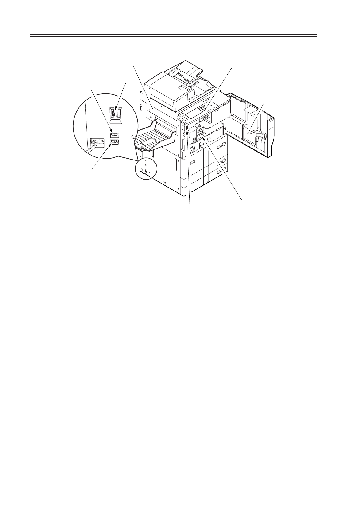
CHAPTER 1 GENERAL DESCRIPTION
[7]
[8]
[6]
[1]
[2]
[5]
[4]
[3]
[1] Delivery assembly cover
[2] Control panel
[3] Door switch assembly
[4] Feeding assembly releasing lever
[5] Service book case
F01-301-02 External View 2
[6] Leakage breaker
[7] Cassette heater switch
[8] Environment switch
1-14 S
COPYRIGHT
©
2001 CANON INC. 2000 2000 2000 2000 CANON iR5000i/iR6000i REV.0 JUNE 2001
 Loading...