

Page 1
DADF-A1
REVSION 0
DEC. 1998
COPYRIGHT © 1998 CANON INC. CANON DADF-A1 REV.0 DEC. 1998 PRINTED IN JAPAN (IMPRIME AU JAPON)
FY8-13FW-000
Page 2

IMPORTANT
THIS DOCUMENTATION IS PUBLISHED BY CANON INC., JAPAN, TO SERVE AS A SOURCE
OF REFERENCE FOR WORK IN THE FIELD .
SPECIFICATIONS AND OTHER INFORMATION CONTAINED HEREIN MAY VARY SLIGHTLY
FROM ACTUAL MACHINE VALUES OR THOSE FOUND IN ADVERTISING AND OTHER
PRINTED MATTER.
ANY QUESTIONS REGARDING INFORMA TION CONTAINED HEREIN SHOULD BE DIRECTED
TO THE COPIER SERVICE DEPARTMENT OF THE SALES COMPANY.
THIS DOCUMENT ATION IS INTENDED FOR ALL SALES AREAS, AND MA Y CONTAIN INFORMATION NOT APPLICABLE TO CER TAIN AREAS.
COPYRIGHT © 1998 CANON INC.
Printed in Japan
Imprimé au Japon
Use of this manual should be strictly supervised to avoid disclosure of confidential
information.
Prepared by
OFFICE IMAGING PRODUCTS TECHNICAL SUPPORT DEPARTMENT 1
OFFICE IMAGING PRODUCTS TECHNICAL SUPPORT DIVISION
CANON INC.
5-1, Hakusan, 7-chome, Toride-City , Ibaraki-Pref ., 302-8501, J apan
COPYRIGHT © 1998 CANON INC. CANON DADF-A1 REV.0 DEC. 1998 PRINTED IN JAPAN (IMPRIME AU JAPON)
Page 3

INTRODUCTION
This Service Manual provides information needed to service the DADF in the field. This Service
Manual consists of the following chapters:
Chapter 1 “General Description” introduces the DADF’s features and specifications, and
shows how to operate it.
Chapter 2 “Basic Operation” introduces the ADAF’s mechanical and electrical systems; it also
explains the principles used in these systems and the timing at which they are
operated with reference to the ADAF’s electrical circuitry.
Chapter 3 “Mechanical System” explains the ADAF’s mechanical construction and how its
parts may be disassembled/assembled and adjusted.
Chapter 4 “Maintenance and Servicing” provides tables of periodically replaced parts and
consumables/durables and scheduled servicing charts.
Chapter 5 “Troubleshooting” provides tables of maintenance/inspection, standards/
adjustments, and problem identification (image fault/malfunction).
Appendix contains a general timing chart and general circuit diagrams.
The descriptions in this Service Manual are subject to change without notice for product
improvement or other purposes, and major changes will be communicated in the form of Service
Information bulletins.
All service persons are expected to have a good understanding of the contents of this Service
Manual and all relevant Service Information bulletins, and be able to identify and isolate faults in the
machine.
COPYRIGHT © 1998 CANON INC. CANON DADF-A1 REV. 0 DEC. 1998 PRINTED IN JAPAN (IMPRIME AU JAPON)
i
Page 4

Page 5

CONTENTS
CHAPTER 1 GENERAL DESCRIPTION
I. FEATURES .................................1-1
II. SPECIFICATIONS ......................1-2
A. DADF-A1 ................................1-2
III. NAMES OF PARTS .................... 1-4
A. Exter nal View .........................1-4
B. Cross Section.........................1-4
CHAPTER 2 BASIC OPERATION
I. BASIC CONSTRUCTION........... 2-1
A. Outline of the Electrical Circuitry.
...............................................2-1
B. Communication with the Copier
...............................................2-2
C. Inputs to the DADF Controller
PCB........................................2-3
D . Outputs to the DADF Controller
PCB........................................2-5
II. BASIC OPERATION ................... 2-6
A. Outline.................................... 2-6
B. Operation ............................... 2-7
C. Detecting Originals .............. 2-12
D. Picking Up Originals ............2-17
IV. OPERATION ...............................1-5
A. Original Set Indicator .............1-5
B. Warning and Actions ..............1-5
C. Routine Maintenance by the
User........................................1-6
E. Reversal............................... 2-25
F. Reduced Page Composition
............................................. 2-27
G. Delivery................................ 2-34
H. Stamping Function............... 2-40
I. Controlling the Pick-Up Motor
.............................................2-43
J. Controlling the Belt Motor
.............................................2-45
K. Detecting Original Jams
.............................................2-47
L. Improper Placement of
Originals...............................2-50
III. POWRE SUPPLY .....................2-53
A. Outline .................................. 2-53
COPYRIGHT © 1998 CANON INC. CANON DADF-A1 REV.0 DEC. 1998 PRINTED IN JAPAN (IMPRIME AU JAPON)
iii
Page 6

CHAPTER 3 MECHANICAL SYSTEM
I. BASIC CONSTRUCITON ........... 3-1
A. External Covers .....................3-1
B. Switches .................................3-3
C. Adjusting the DADF Height
............................................... 3-5
II. DRIVE SYSTEM ......................... 3-6
A. Removing the Pick-Up
Motor Unit...............................3-6
B. Removing the Feeder Motor Unit
...............................................3-6
C. Belt Motor...............................3-7
D. Removing the Clutch Unit
...............................................3-9
E. Delivery Motor ......................3-10
III. FEEDING SYSTEM .................. 3-11
A. Pick-Up Roller ...................... 3-11
B. Removing the Separation
Belt Unit ............................... 3-12
C. Feeding Roller Unit .............. 3-12
D. Registration Roller ............... 3-14
E. Delivery/Resersing Roller
............................................. 3-16
F. Delivery Roller Unit
(bottom Pick-up Mode).........3-20
G. Delviery Roller Unit
(top Pick-up Mode)...............3-20
H. Reversing Guide.................. 3-22
I. Stopper Plate Solenoid........ 3-24
J. Positioning the Paper Retaining
Plate Solenoid (SL2)............3-24
K. Positioning the Paper Deflecting
Solenoid (SL3) ..................... 3-26
L. Stamp Solenoid ................... 3-26
M. Feeding Belt......................... 3-28
IV. CLEANING................................ 3-30
A. Belt Assembly ...................... 3-30
B. Sensors ................................ 3-30
C. Separation Flapper .............. 3-33
D. Separation Guide.................3-33
V. FEEDING ..................................3-34
A. Pick-Up Drive Assembly ......3-34
B. Right Delivery Drive
Assembly ............................. 3-34
CHAPTER 4 MAINTENANCE AND SERVICING
I. PERIODICALLY REPLACED
PART S ........................................ 4-1
II. CONSUMABLES AND
DURABLES ................................ 4-1
III. SCHEDULED SERVICING
CHART........................................4-2
iv
COPYRIGHT © 1998 CANON INC. CANON DADF-A1 REV.0 DEC. 1998 PRINTED IN JAPAN (IMPRIME AU JAPON)
Page 7

CHAPTER 5 TROUBLESHOOTING
I. STANDARDS AND
ADJUSTMENTS ......................... 5-1
A. Mechanical System................5-1
B. Electrical System .................5-17
II. TROUBLESHOOTING..............5-20
A. Troubleshooting
Malfunctions.........................5-20
III. ARRAIGMENT OF THE ELECTRI-
CAL PARTS .............................. 5-24
A. Motors, Solenoids, and
Sensors................................5-24
APPENDIX
A. GENERAL TIMING CHART....... A-1
B. NAMES AND ABBREVIATIONS OF
SIGNALS .................................... A-4
C. DADF-A1 GENERAL CIRCUIT
DIAGRAM .................................. A-5
B. PCB......................................5-26
IV. VARIABLE RESISTORS, LIGHT-
EMITTING DIODES, AND CHECK
PINS BY PCB ........................... 5-27
A. DADF Controller PCB.......... 5-27
B. Indicator PCB....................... 5-29
C. DIP Switch Functions ...........5-30
V. SELF DIAGNOSIS .................... 5-32
A. DADF Self Diagnosis........... 5-32
D. DADF CONTROLLER CIRCUIT
DIAGRAM .................................. A-6
E. DISPLAY BOARD .................... A-13
F. SPECIAL TOOLS..................... A-14
G. SOLVENTS AND OILS ............ A-15
COPYRIGHT © 1998 CANON INC. CANON DADF-A1 REV.0 DEC. 1998 PRINTED IN JAPAN (IMPRIME AU JAPON)
v
Page 8

Page 9

CHAPTER 1
GENERAL DESCRIPTION
I. FEATURES.................................. 1-1
II. SPECIFICATIONS ....................... 1-2
A. DADF-A1....................................1-2
III. NAMES OF PARTS ..................... 1-4
A. Exter nal View .............................1-4
B. Cross Section .............................1-4
COPYRIGHT © 1998 CANON INC. CANON DADF-A1 REV.0 DEC. 1998 PRINTED IN JAPAN (IMPRIME AU JAPON)
IV. OPERATION ................................1-5
A. Original Set Indicator..................1-5
B. Warnings and Actions ................1-5
C. Routine Maintenance
by the User .................................1-6
Page 10

Page 11

CHAPTER 1 GENERAL DESCRIPITON
I. FEATURES
1. Two Types of Pick-Up Mode
Top pick-up: Pick-up starts with the top page.
Bottom pick-up: Pick-up starts with the bottom page.
2. Stamp Marking
The machine can mark originals with a stamp to indicate that they have been processed for fax
transmission.
3. Original Size Identification
The machine can identify the size of an original in terms of its length (feeding direction) and
width for communication to its host copier.
COPYRIGHT © 1998 CANON INC. CANON DADF-A1 REV.0 DEC. 1998 PRINTED IN JAPAN (IMPRIME AU JAPON)
1-1
Page 12

CHAPTER 1 GENERAL DESCRIPITON
II. SPECIFICATIONS
A. DADF-A1
Item
Original pick-up
Original placement 1
Original placement 2
Original pick-up
Original type
Original size
Original tray
Delivery tray
Original processing
mode
Original size
identification
Residual original
detection
Continuous feeding
Size mix
Communication with
copier
Power supply
Maximum power
consumption
Weight
Dimensions (mm)
Serial No.
Operating conditions
Temperature Humidity
Specifications
Circulating, auto duplexing pick-up method
Face up
Center reference
Top pick-up
Bottom pick-up
Sheet (50 to 105 g/m2), single-sided sheet,
double-sided sheet
A5/STMT to A3/279×432 mm (11"×17")
If small size, 50 sheets, 5.5 mm high max.
(A5, B5, B5R, A4, A4R, STMT, LTR, LTRR)
If large size, 25 sheets (B4, A3, LGL,
279×432 mm (11"×17")
If small size, 50 sheets (A5, B5, B5R, A4,
A4R, STMT, LTR, LTRR)
If large size, 25 sheets (B4, A3, LGL,
279×432 mm (11"×17")
Single-sided, double-sided, reduce image
composition
Length (feeding direction) and width
Possible in conjunction with the host copier.
Possible
Possible
Possible
IPC 2
24 VDC (from the host copier)
170 W or less
14.1 kg (approx.)
684 (W) × 527 (D) × 161 (H)
AB ZLZ xxxxx
INCH/A ZNE xxxxx
A ZNF xxxxx
INCH/AB ZNG xxxxx
Same as the host copier.
Remarks
See p.2-17.
No extra length original.
Paper of 80 g/m2 or less.
Paper of 80 g/m2 or less.
Paper of 80 g/m2 or less.
Paper of 80 g/m2 or less.
For fax processing only.
Of the same width only.
For fax processing only.
Not including the
delivery tray.
Not including the
delivery tray.
1-2
The above specifications are subject to change for product improvement.
Table 1-201
COPYRIGHT © 1998 CANON INC. CANON DADF-A1 REV.0 DEC. 1998 PRINTED IN JAPAN (IMPRIME AU JAPON)
Page 13

CHAPTER 1 GENERAL DESCRIPITON
Note:
The following must not be used as originals:
• A transparency or paper with an opacity of 80% or less.
• A carbon-backed sheet.
• A sheet with paste-ups or binding.
• A sheet with a cut-off, hole, or tear.
• A sheet with a clip or glue.
• A sheet with curling, wrinkling, or creasing.
Caution:
Do not feed the same original more than 30 times to protect against damage.
COPYRIGHT © 1998 CANON INC. CANON DADF-A1 REV.0 DEC. 1998 PRINTED IN JAPAN (IMPRIME AU JAPON)
1-3
Page 14
CHAPTER 1 GENERAL DESCRIPITON
III. NAMES OF PARTS
A. External View
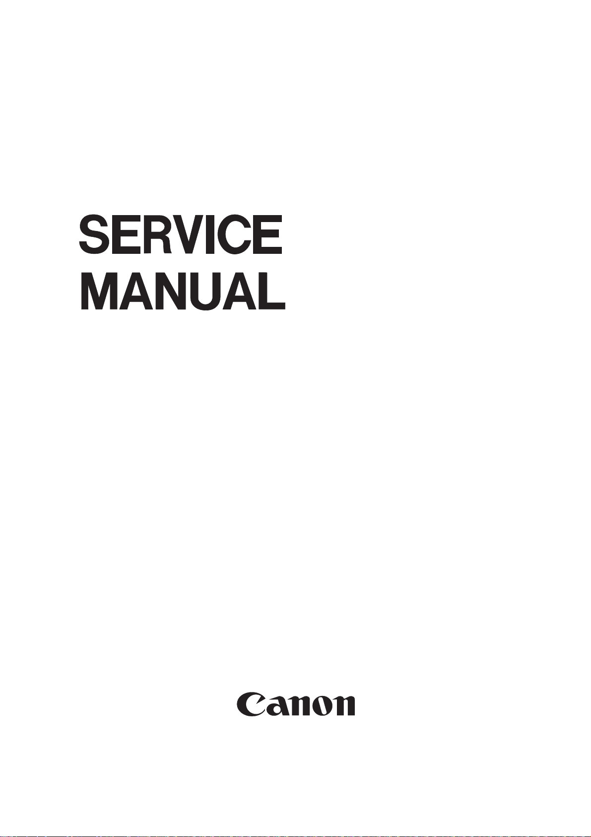
[1] [2] [3] [4] [5] [6] [7] [8]
Figure 1-301
[1] Upper cover
[2] Side guide
[3] Re-circulating guide
[4] Original Set indicator
[5] Original tray
[6] Sub tray
[7] Body cover
[8] Original delivery tray
B. Cross Section
[1] [2] [3] [4] [5] [6] [7] [8] [9] [10]
[1] Delivery/reversing roller
[2] Paper deflecting plate
[3] Feeding roller
[4] Separation belt
[5] Separation flapper
[6] Pre-separation guide
[16] [15] [14] [13] [12] [11]
Figure 1-302
[7] Delivery/pick-up roller
[8] Paper retaining plate
[9] Pick-up roller
[10] Delivery roller
[11] Feeding belt link roller
[12] Retaining rolls
[13] Feeding belt
[14] Paper stopper plate
[15] Feeding belt drive roller
[16] Registration roller
1-4
COPYRIGHT © 1998 CANON INC. CANON DADF-A1 REV.0 DEC. 1998 PRINTED IN JAPAN (IMPRIME AU JAPON)
Page 15
CHAPTER 1 GENERAL DESCRIPITON
IV. OPERATION
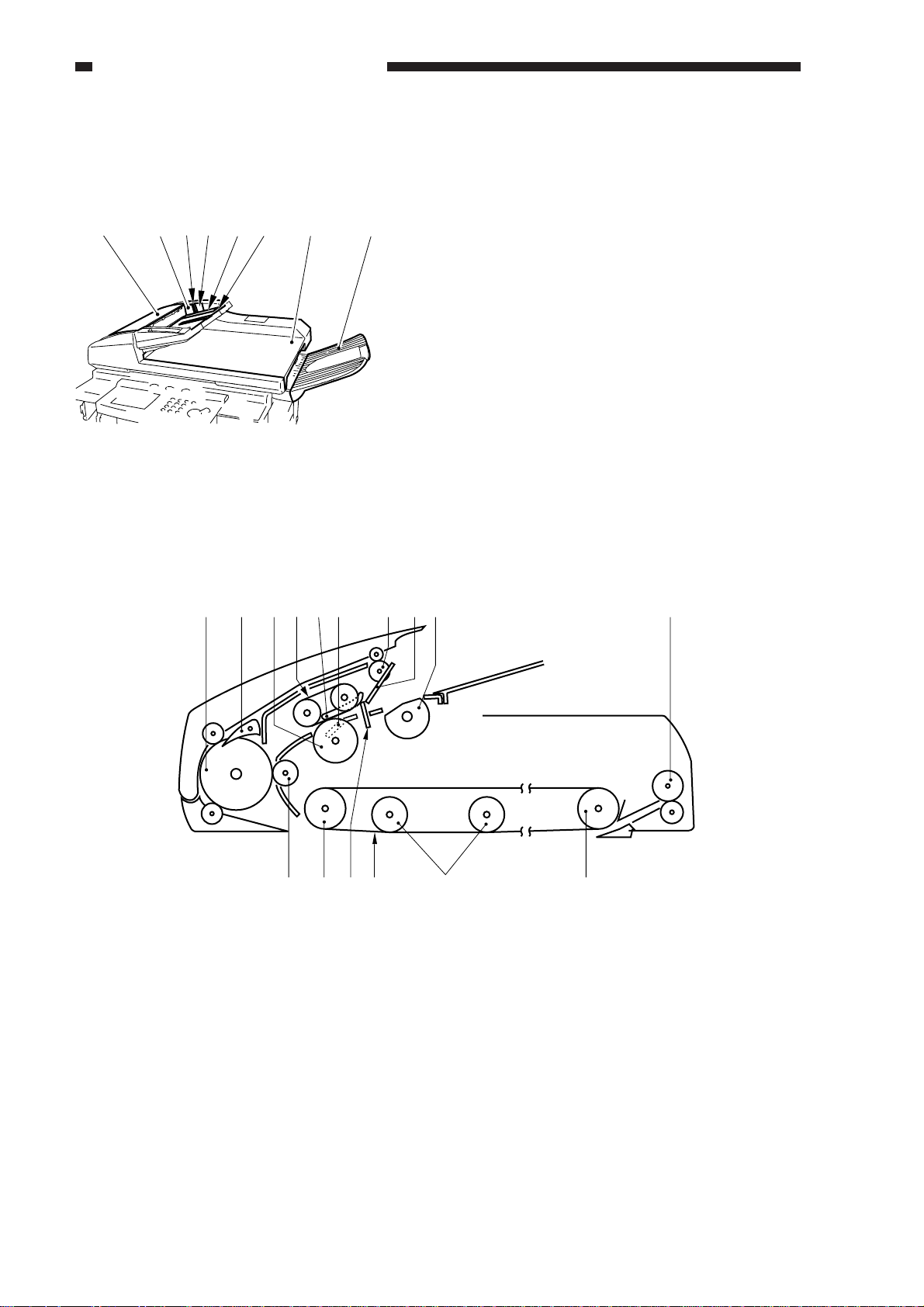
A. Original Set Indicator
The Original Set indicator turns on when
an original is placed on the original tray, and
flashes when an original jams.
A4/B5
A3/B4
Figure 1-401
Operation
1) If the original is B5R or larger or is A5 in
feeding length, open the original sub tray.
2) Set the side guide to suit the size of the
original.
B. Warnings and Actions
If the Original Set indicator flashes while
an original is being fed, suspect a jam and
perform the following:
1) Remove the originals from the original
tray.
2) Open the upper cover, and remove the jam.
Then, open the DADF to reset the
warning. (If any original is on the
copyboard glass, remove it.)
Caution:
If the jam is in the copier, the copier will
run jam recovery mode and will
automatically set the originals. Do not
open the DADF to reset.
3) Set the originals in correct order, and set
the stack in the DADF.
Reference:
The side guide lock must be removed if
the width of the original is larger than 297
mm (A4/A3). For details, see 3. “Side
Guide Lock” on p. 3-3.
3) Place the originals with the first page on
top.
4) As needed, set the appropriate copying
mode on the copier.
5) Press the copier’s Copy Start key.
COPYRIGHT © 1998 CANON INC. CANON DADF-A1 REV.0 DEC. 1998 PRINTED IN JAPAN (IMPRIME AU JAPON)
1-5
Page 16
CHAPTER 1 GENERAL DESCRIPITON
C. Routine Maintenance by the User
Instruct the user to clean the following at least once a week:
1. Copyboard Glass
Wipe it with a cloth moistened with water or alcohol; then, dry-wipe it.
2. Feeding Belt
Wipe it with water or alcohol.
3. Other Parts
Clean all other parts of the DADF (if soiled) using a solution of mild detergent; then, dry-wipe
them to remove any residue.
4. Feeding Belt and Feeding Roller
Execute cleaning mode in the copier’s user mode.
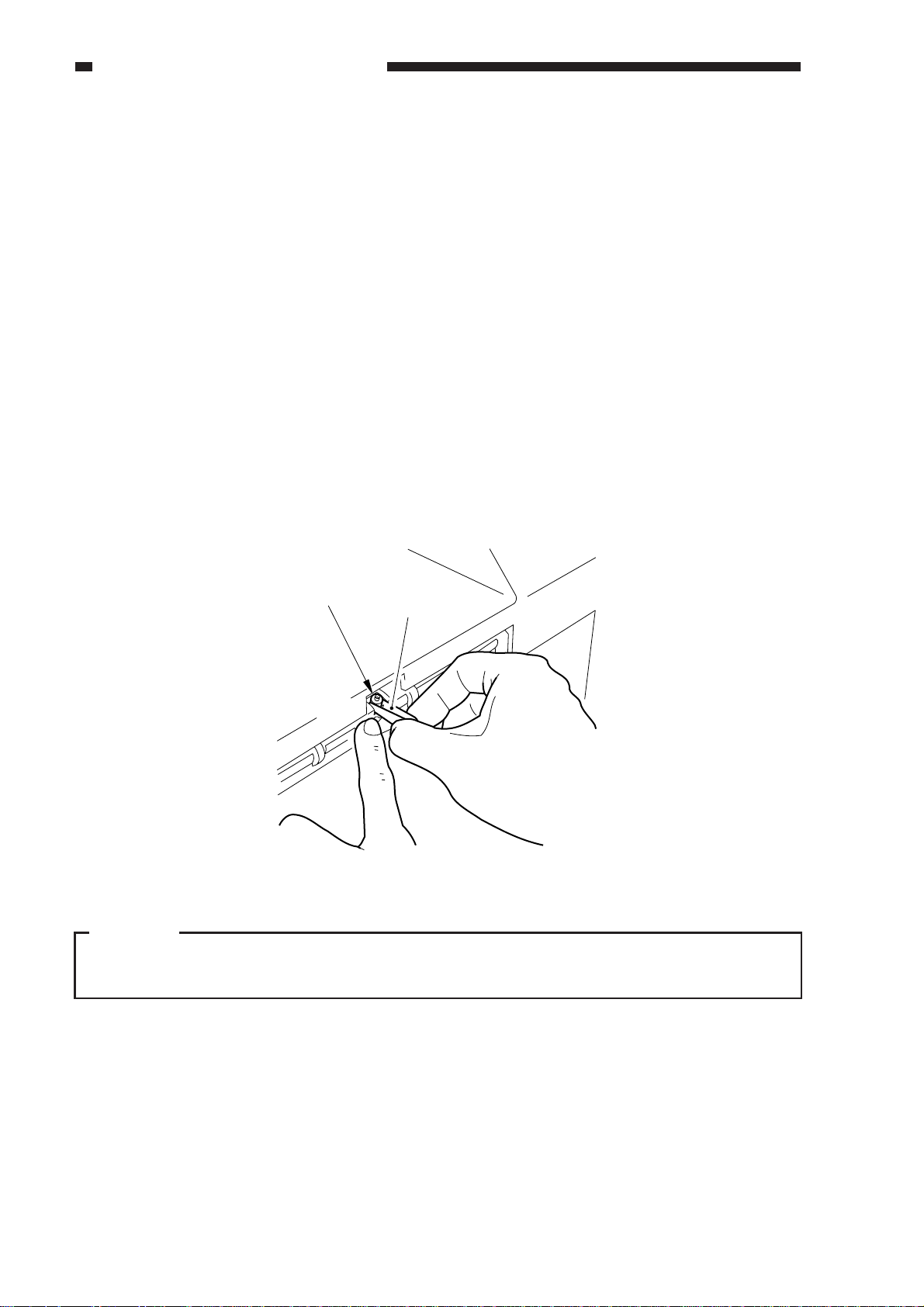
5. Stamp
If markings start to be fuzzy, replace the stamp using tweezers.
Stamp
Tweezers
Figure 1-402
Caution:
Do not touch the stamp face. If your skin has come into contact with its ink, be sure to wash it
with water immediately.
1-6
COPYRIGHT © 1998 CANON INC. CANON DADF-A1 REV.0 DEC. 1998 PRINTED IN JAPAN (IMPRIME AU JAPON)
Page 17

CHAPTER 2
BASIC OPERATION
I. BASIC CONSTRUCTION ............2-1
A. Outline of the Electrical
Circuitry ......................................2-1
B. Communication with the Copier .2-2
C. Inputs to the D ADF
Controller PCB ........................... 2-3
D. Outputs to the DADF Controller PCB
....................................................2-5
II. BASIC OPERATION .................... 2-6
A. Outline ........................................ 2-6
B. Operation .................................... 2-7
C. Detecting Originals ................... 2-12
COPYRIGHT © 1998 CANON INC. CANON DADF-A1 REV.0 DEC. 1998 PRINTED IN JAPAN (IMPRIME AU JAPON)
D. Picking Up Originals ................ 2-17
E. Reversal ................................... 2-25
F. Reduced Page Composition .... 2-27
G. Delivery .................................... 2-34
H. Stamping Function ................... 2-40
I. Controlling the Pick-Up Motor ..2-43
J. Controlling the Belt Motor.........2-45
K. Detecting Original Jams ...........2-47
L. Improper Placement of
Originals ...................................2-50
III. POWRE SUPPLY ...................... 2-53
A. Outline ...................................... 2-53
Page 18

Page 19
CHAPTER 2 BASIC OPERATION
I. BASIC CONSTRUCTION
A. Outline of the Electrical Circuitry
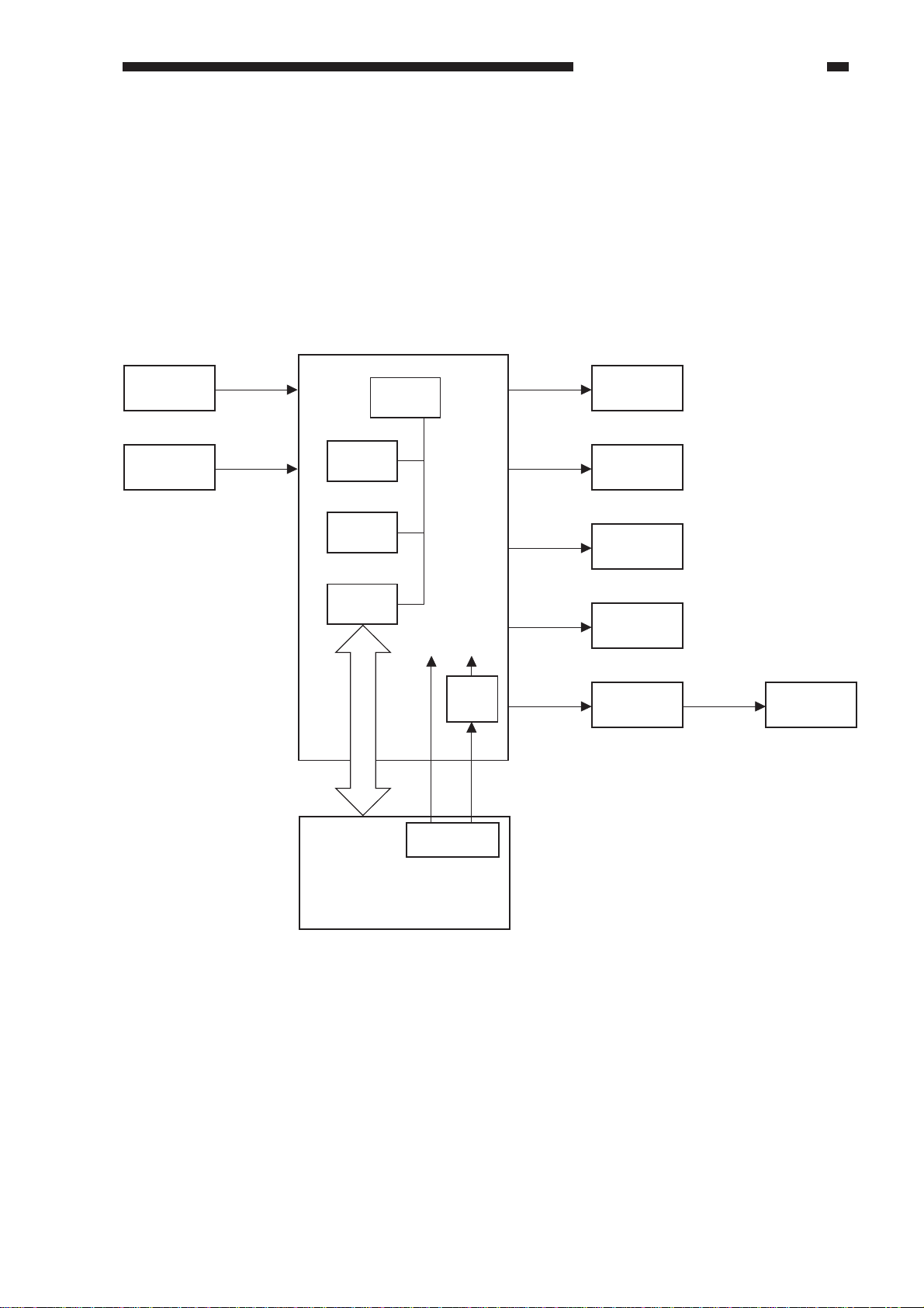
The machine’s electrical mechanisms are controlled by the DADF controller PCB. A
microprocessor (CPU) is used on the DADF controller PCB, and the microprocessor reads the input
signals from the sensors and the copier and generates signals used to drive DC loads (motors,
solenoids) at such times as programmed in advance.
DADF controller PCB
Sensor
V ariable
resistor
CPU
(Q1)
ROM
(Q2)
RAM
(Q4)
Communication
IC(Q3)
24V
Power supply
5 VDC
power
supply
J2-1
circuit
5V
J1-6
Motor
Solenoid
Clutch
Brake
Indicator
LED PCB
Motor
Copierk
Figure 2-101
COPYRIGHT © 1998 CANON INC. CANON DADF-A1 REV.0 DEC. 1998 PRINTED IN JAPAN (IMPRIME AU JAPON)
2-1
Page 20
CHAPTER 2 BASIC OPERATION
B. Communication with the Copier
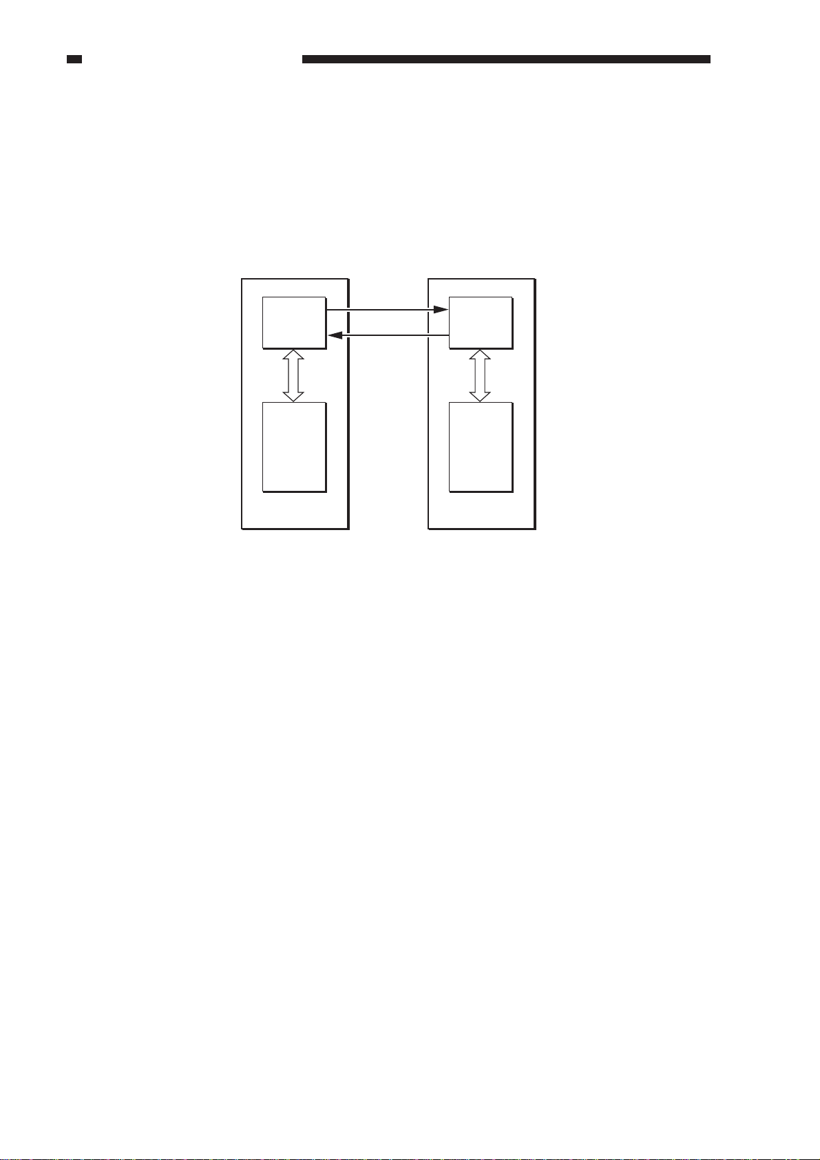
The operation modes selected on the copier are communicated to the machine in an IPC
communication method. Likewise, the operation states of the machine are communicated to the
copier in an IPC communication.
If an error occurs in the IPC communication, the copier’s self diagnosis function turns on to
indicate “E400” or “E712” on its control panel.
RSOUT
Communication
IC
RSIN
Communication
IC
CPUCPU
Copier DADF
Figure 2-102
2-2
COPYRIGHT © 1998 CANON INC. CANON DADF-A1 REV.0 DEC. 1998 PRINTED IN JAPAN (IMPRIME AU JAPON)
Page 21
DADF switch
MS1
MS2
S1
J203
J205
LED3
S3
S4
S5
S6
S7
J212
COM J2-3
+24V
+5V
+5V
+5V
+5V
+5V
+5V
RFC
EMPS
ENTS
CVRSW
DCTS
EJTS1
SPRS
UPCC1
-4
1-2
J5-7
J9-B10
-B9
-B12
J9-B6
J5-3
J9-A1
J9-A4
-A6
-A5
-A3
-A2
-1
-2
-B8
-B7
-B11
-8
-9
3
1
21
3
1
2
3
J207
J208
1
2
3
1
2
3
1
2
3
1
2
1
3
2
1
3
2
3
1
2
2
41
2
J3-
NO
COM
NO
Upper cover switch
Original tray
paper sensor
Registration
paper sensor
Upper cover
sensor
Pick-up roller sensor
Delivery sensor 1
Pick-up sensor
DADF controller PCB
When the RDF is open, '0'.
When the upper cover is open, '0'.
When an original blocks the sensor, '1'.
When an original blocks the sensor, '1'.
When the upper cover is open, '0'.
(The light-blocking plate is at the sensor.)
When the pick-u roller is
at the home position, '1'.
(The light-blocking plate is at the sensor.)
When an original is detected, '1'.
(The light-blocking plate is at the sensor.)
When an original is detected, '1'.
(The light-blocking plate is at the sensor.)
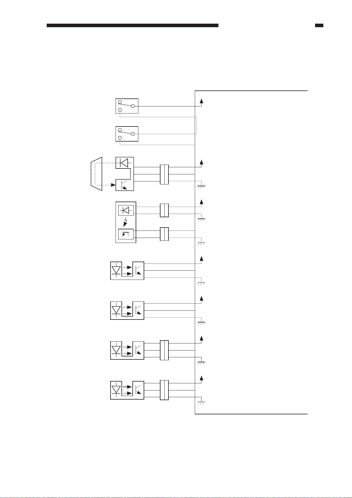
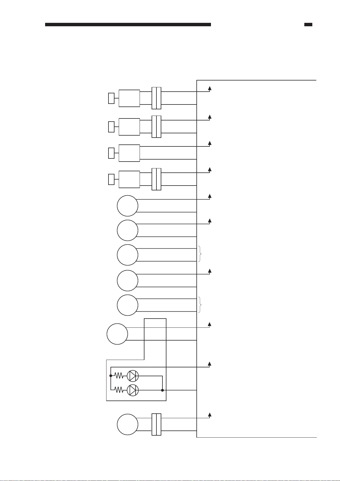
C. Inputs to the DADF Controller PCB
1. Inputs to the DADF Controller PCB (1/2)
CHAPTER 2 BASIC OPERATION
Figure 2-103
COPYRIGHT © 1998 CANON INC. CANON DADF-A1 REV.0 DEC. 1998 PRINTED IN JAPAN (IMPRIME AU JAPON)
2-3
Page 22
CHAPTER 2 BASIC OPERATION
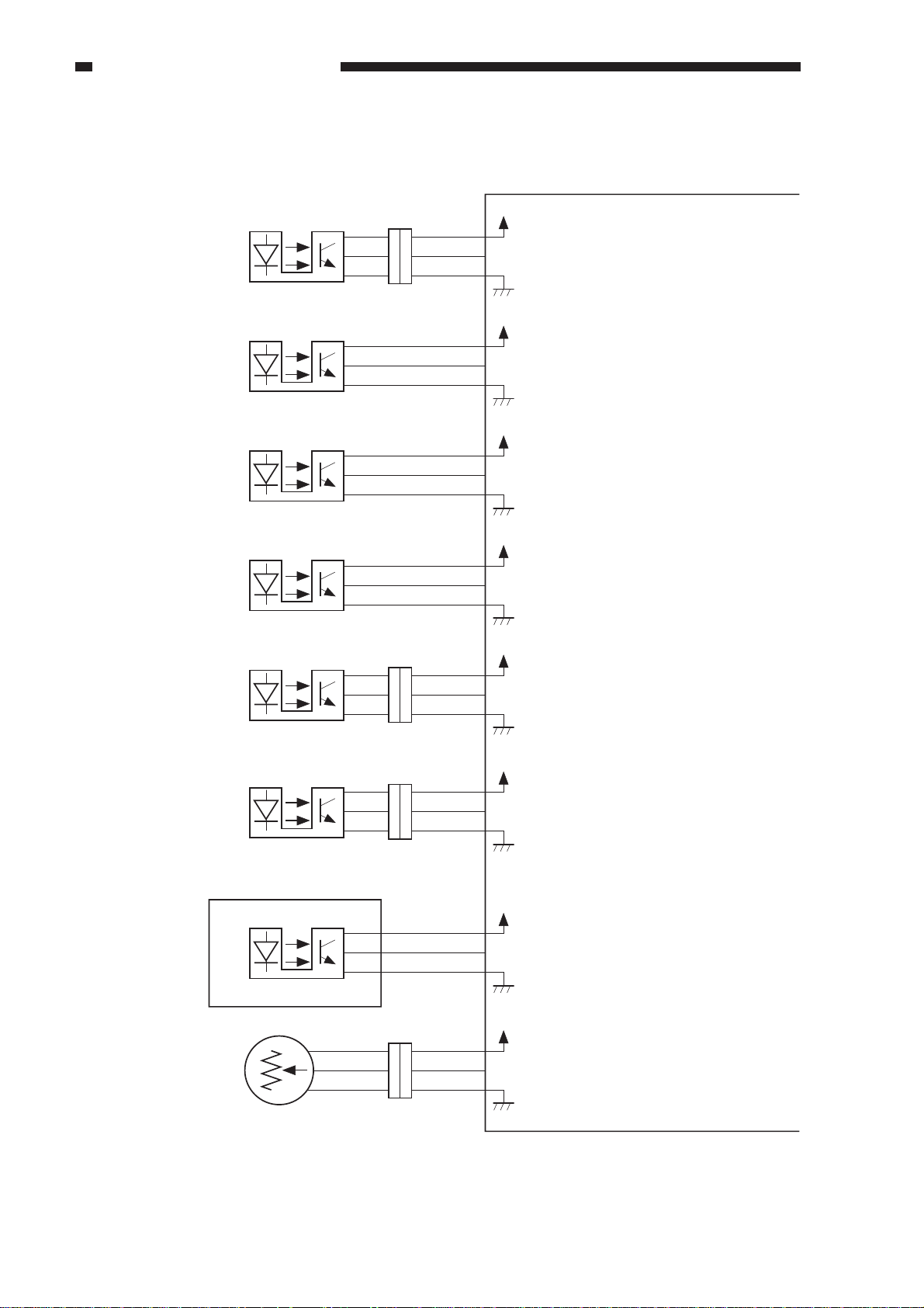
2. Inputs to the DADF Controller PCB (2/2)
DADF controller PCB
Reversal sensor S8
Feeder motor
S9
clock sensor
Belt motor
S10
clock sensor
Registration roller
S11
clock sensor
Delivery sensor 2 S12
J209
3
1
2
1
2
3
1
2
3
1
2
3
3
1
2
1
3
2
1
3
2
J219
3
1
2
3
1
2
J9-A7
-A9
-A8
J9-A12
-A11
-A10
J9-B5
-B4
-B3
J5-4
-5
-6
J14-4
-6
-5
+5V
TURNS
+5V
FCLK
+5V
BCLK1
+5V
RCLK
+5V
EJTS2
When an original is detected, '1'.
(When the light-blocking plate is
at the sensor.)
While the feeder motor is rotating,
alternates '1' and '0'.
While the feeder motor is rotating,
alternates '1' and '0'.
While the feeder motor is rotating,
alternates '1' and '0'.
When an original is detected, '1'.
(When the light-blocking plate is
at the sensor.)
Delivery motor
clock sensor
Re-circulation
sensor
Original width
detecting VR
S13
Display PCB
S14
J219
1
3
2
2
3
1
J101-3
-2
-1
J218
3
2
1
J14-3
4
-2
5
-1
6
J8-3
-2
-1
1
J8-7
2
-8
3
-9
+5V
ECLK
+5V
RSS
+5V
WIDTH
While the delivery motor is rotating,
alternates '1' and '0'.
When the re-circulation bar is set
on the top original, '1'.
Detects the width of the original
stacked on the original tray.
2-4
COPYRIGHT © 1998 CANON INC. CANON DADF-A1 REV.0 DEC. 1998 PRINTED IN JAPAN (IMPRIME AU JAPON)
Page 23
D. Outputs to the DADF Controller PCB
1. Outputs to the DADF Controller PCB (1/1)
CHAPTER 2 BASIC OPERATION
Stopper plate solenoid
Paper retaining plate
solenoid
Paper deflecting plate
solenoid
Stamp solenoid
Clutch
Brake
Pick-up motor
SL1
SL2
SL3
SL4
CL
BK
M1
2
1
2
1
2
1
J217
J216
J220
STPSL
WGTSL
FLPSL1
SMPSL
+24V
When '0', the solenoid (SL1) turns on.
(The stopper plate moves down.)
+24V
When '0', the solenoid (SL2) turns on.
(The paper retaining plate moves down.)
+24V
When '0', the solenoid (SL3) turns on.
(The paper deflecting plate operates.)
+24V
When '0', the solenoid (SL4) turns on.
(The stamp puts a marking on the
1
2
1
2
1
2
J5-10
-11
J5-12
-13
J9-B2
-B1
J14-9
-10
original.)
J13-1
-2
J6-1
-2
J12-1
-2
J11-1
+24V
CL
+24V
BK
See p. 2-43.
+24V
When '0', the clutch (CL1)
turns on.
When '0', the brake (BK1)
turns on.
Feeder motor
Belt motor
Re-circulation motor
Delivery motor
M2
M3
J102-1
M4
-2
Display PCB
M5
J101 -5
LED101
LED102
J221
3
2
-6
J101-4
1
2
FMPWM
-2
J7-1
-2
J8-5
RSDRV
-6
J14-8
-7
-3
ORGLED
-4
EMPWM
-3
When '0', the feeder motor (M2)
turns on.
See p. 2-45.
+5V
When '0', the re-circulation motor (M4)
turns on.
+5V
When '0', the Original Set indicator
turns on.
+24V
When '0', the delivery motor (M5)
turns on.
COPYRIGHT © 1998 CANON INC. CANON DADF-A1 REV.0 DEC. 1998 PRINTED IN JAPAN (IMPRIME AU JAPON)
2-5
Page 24
CHAPTER 2 BASIC OPERATION
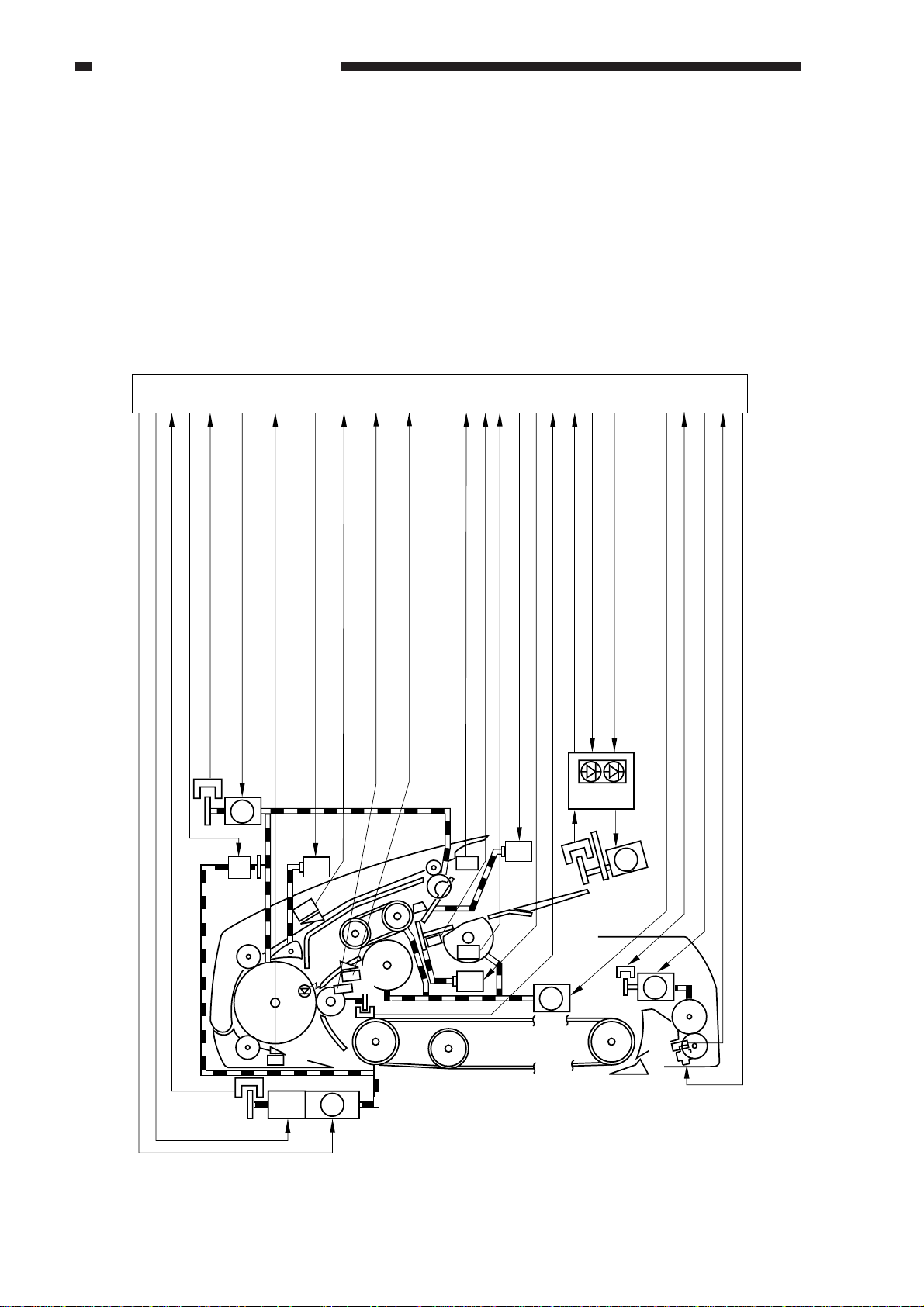
II . BASIC OPERATION
A. Outline
The machine uses four motors and one clutch to pick up, feed, and deliver originals.
The pick-up motor (M1) serves to pick up originals. The feeder motor (M2) serves to reverse and
deliver originals. The belt motor (M3) moves and stops originals to and on the copyboard glass, and
delivers them. The delivery motor (M3) operates to deliver originals to the delivery tray.
The clutch (CL) is used to engage or disengage the drive of the feeder motor (M2) and the belt
motor (M3).
DADF controller PCB
Belt motor clock signal
Feeder belt brake drive signal
Belt motor drive signal
Clutch drive signal
Feeder motor clock signal
S9
S10
Delivery detection signal 1
Reversal/feeder paper detection signal
Feeder motor drive signal
M2
CL
Paper deflecting plate solenoid drive signal
SL3
S6
S8
BK M3
Pick-up registration signal
S7
S3
S11
Pick-up paper detection signal
S1
Original tray paper signal
Pick-up roller home position detection signal
Upper cover open/closed detection signal 2
S4
S5
SL1
Stopper plate solenoid drive signal
Paper holding solenoid drive signal
SL2
M1
Registration roller clock signal
Last original detection signal
Indicator
S14
Delivery motor clock signal
Original set indicator ON signal
Re-circulator motor drive signal
PCB
S13
Pick-up motor drive signal
M4
M5
S12
SL4
Delivery detection signal 2
Delivery motor drive signal
Stamp solenoid drive signal
2-6
Figure 2-201
COPYRIGHT © 1998 CANON INC. CANON DADF-A1 REV.0 DEC. 1998 PRINTED IN JAPAN (IMPRIME AU JAPON)
Page 25
CHAPTER 2 BASIC OPERATION
B. Operation
The machine enables the following six
operations:
1. Bottom pick-up
2. Double-sided original to single-sided
copy
3. 2 small-size originals to reduced page
composition
4. Single-sided original to double-sided
copy
5. Double-sided original to double-sided
copy
Using auto duplexing unit.
6. Top pick-up mode original feeding
The machine feeds originals in any of
the following five ways according to the
instructions from the copier:
1. Bottom Pick-Up Mode
The machine picks up the originals on the
original tray from the bottom (last page of the
stack), and places each on the copyboard glass.
After copying, it moves the original from
the copyboard glass to the original tray.
Original
Original tray
Original set
Pick-up 2
Copying
Delivery 1
Delivery 2
Figure 2-202
COPYRIGHT © 1998 CANON INC. CANON DADF-A1 REV.0 DEC. 1998 PRINTED IN JAPAN (IMPRIME AU JAPON)
2-7
Page 26
CHAPTER 2 BASIC OPERATION
2. Double-Sided Original Mode
When copying the face (1st side) and the back (2nd side) of an original, the machine
automatically reverses the original.
Pick-Up Operation
Picks up an original for the 1st side.
Reverses the original from the 1st side
to the 2nd side.
Scanner
Reverses the original from the
2nd side to the 1st side.
Copies the 2nd side.
Copies the 1st side.
2-8
Delivers the original.
Figure 2-203
COPYRIGHT © 1998 CANON INC. CANON DADF-A1 REV.0 DEC. 1998 PRINTED IN JAPAN (IMPRIME AU JAPON)
Page 27
CHAPTER 2 BASIC OPERATION
3. Reduced Page Compositon Mode
When reducing and copying two originals in page composition mode, the machine automatically
picks up two originals and places them on the copyboard glass side by side. Table 2-201 shows the
sizes of originals that may be used in the machine.
1st original
Picks up the 1st original.
A/B-configured
A5
B5
A4
Table 2-201
2nd original
INCH-configured
STMT
LTR
–
Reverses the original from the 1st side
to the 2nd side.
Picks up the 2nd original
While reversing the 1st original, picks up
the 2nd original.
(At this time, the order of originals is switched.)
Feeds the 2nd original and the 1st original.
Copying
1st original
2nd original
Delivers the 1st original, and delivers
the 2nd original.
Figure 2-204
COPYRIGHT © 1998 CANON INC. CANON DADF-A1 REV.0 DEC. 1998 PRINTED IN JAPAN (IMPRIME AU JAPON)
2-9
Page 28
CHAPTER 2 BASIC OPERATION
4. Top Pick-Up Feeding
The machine picks up the originals on the
original tray from the top (first page of the
stack), and places them on the copyboard glass.
Each time an original has been read, the
machine moves the original from the
copyboard glass to the original delivery tray.
Placement
Pick-up
Reading
Delivery 1
Delivery 2
2-10
Figure 2-205
COPYRIGHT © 1998 CANON INC. CANON DADF-A1 REV.0 DEC. 1998 PRINTED IN JAPAN (IMPRIME AU JAPON)
Page 29

CHAPTER 2 BASIC OPERATION
5. Recirculating Mode
If the copier is not equipped with a sorter, this mode enables sorting of copies. Originals are
copied one after another until one set of copies have been made; and this operation is repeated until as
many sets as desired have been made.
Operation
1) Set originals on the original tray.
2) Select sort mode on the copier.
3) Enter a number (of sets) on the copier’s keypad.
4) Press the Copy Start key.
COPYRIGHT © 1998 CANON INC. CANON DADF-A1 REV.0 DEC. 1998 PRINTED IN JAPAN (IMPRIME AU JAPON)
2-11
Page 30
CHAPTER 2 BASIC OPERATION
C. Detecting Originals
1. Outline
The machine has the following four types
of document detection:
1. Detects the presence/absence of an
original on the original tray.
2. Detects the size of originals place on
the original try.
3. Detects the number of originals that
have been copied.
4. Detects the trailing edge of the last
original.
2. Detecting the Presence/Absence of
an Original
The presence/absence of an original on the
original tray is detected by the original tray
paper sensor (PS1).
When an original is set on the original tray,
the light between the original tray paper sensor
(S1) and the prism is blocked, causing the
original tray paper sensor (S1) to generate the
original detection signal (EMPS).
In response to the original detection signal
(EMPS), the DADF controller PCB turns on
the Original Set indicator (LED101, LED102).
Original Set indicator
Original
Original tray
Figure 2-207
DADF controller PCB
LED 101,102
Prism
Original
S1
S11
Figure 2-206
Original Set
indicator ON
signal
Indicator
PCB
Original tray paper signal
2-12
COPYRIGHT © 1998 CANON INC. CANON DADF-A1 REV.0 DEC. 1998 PRINTED IN JAPAN (IMPRIME AU JAPON)
Page 31
CHAPTER 2 BASIC OPERATION
3. Detecting the Size of an Original
a. Outline
The machine detects the size of an original
in relation to the vertical (feeding) and
horizontal directions of the original, ensuring
correct size detection and for use for the
communication protocol of fax mode.
b. Detecting in Vertical (feeding)
Direction
Detection in vertical direction is made by
the registration paper sensor (S3) and the
registration roller clock sensor (S11).
The registration paper sensor detects the
leading and trailing edges of an original, and
the registration roller clock sensor detects the
rotation of the registration roller while the
original moves past the sensor. The rotation of
the registration roller is converted to the length
of the original.
DADF controller PCB
c. Detection in Horizontal Direction
Detection in horizontal direction is made
by the original width detecting volume (VR)
on the original tray. The original width
detecting volume operates in conjunction with
the side guide. As its resistance varies, the
changes are detected by the DADF controller
PCB, which converts them into a length in
horizontal direction.
Side guides
VR
DADF controller PCB
Figure 2-209
Registration
paper sensor
Registration roller
Pick-up detection signal
Registration roller clock signal
Registration roller clock sensor
Figure 2-208
COPYRIGHT © 1998 CANON INC. CANON DADF-A1 REV.0 DEC. 1998 PRINTED IN JAPAN (IMPRIME AU JAPON)
2-13
Page 32

CHAPTER 2 BASIC OPERATION
The copier identifies the size of an original
in terms of a default size based on the results of
vertical and horizontal lengths communicated
by the machine.
Table 2-202 shows the default sizes that
are identified:
d. A Model, A/B Model
Default
B5R
A5
A4R
FOOLSCAP
B5
B4
COMPUTER
paper
A4
A3
Vertical length
257mm
148.5mm
330mm
330mm
182mm
364mm
381mm
210mm
420mm
Original width
177~187mm
205~215mm
252~262mm
274~284mm
292~302mm
f. Inch Model and Inch/AB Model
Default
B5R
A5
A4R
STMT
LTRR
FOOLSCAP
LGL
B5
B4
LTR
COMPUTER
paper
279mm×432mm
(11"×17")
A4
A3
Original
length
257mm
148mm
297mm
140mm
279mm
330mm
356mm
182mm
364mm
216mm
381mm
432mm
210mm
420mm
Original
width
177~187mm
205~213mm
214~221mm
252~262mm
274~284mm
For vertical direction, a deviation of ±10
mm is ignored; for horizontal direction, a
deviation of ±5 mm is ignored; outside the
ranges, the original will be identified as being
of a non-default size.
Table 2-202
e. Inch Model
Default
STMT
LTRR
FOOLSCAP
LGL
LTR
COMPUTER
paper
297mm×432mm
(11"×17")
Original
length
140mm
279mm
330mm
356mm
216mm
381mm
432mm
Original
width
211~221mm
274~284m
For original length, a deviation of ±10 mm
is ignored; for original width, a deviation of ±5
mm is ignored; outside the ranges, the original
will be identified as being of a non-default size.
Table 2-204
In vertical direction, a deviation of ±10 mm
is ignored; in horizontal direction, a deviation
of ±5 mm is ignored; outside the ranges, the
original will be identified as being of a nondefault size.
Table 2-203
2-14
COPYRIGHT © 1998 CANON INC. CANON DADF-A1 REV.0 DEC. 1998 PRINTED IN JAPAN (IMPRIME AU JAPON)
Page 33

CHAPTER 2 BASIC OPERATION
4. Detecting the Number of Originals
The number of originals is detected in
terms of “stack end detection,” “last original
rear edge detection,” and “original count
detection.”
a. Detecting the End of a Stack
The machine picks up and delivers
originals on the same tray, requiring distinction
of originals that have been copied from
originals that have not been copied.
Before picking up originals, the recirculating lever is placed on top of the stack.
The lever will drop on the original tray when
all originals have been picked up, enabling the
re-circulation sensor (S14) to identify the last
original and to generate the last original
detection signal (RSS).
DADF controller PCB
Recirculating lever
b. Detecting the Trailing Edge of the Last
Original
A copier with a long paper path (from the
cassette to the drum) is designed to pick up
copy paper early to speed up copying work. As
such, when the machine picks up the last
original and places it on the copyboard glass,
the next paper is likely to be kept in wait.
To accommodate this, the machine is
designed to pick up originals to suit the timing
at which its host copier picks up copy paper.
If the length of an original is 220 mm or
less, the machine sets the first original on the
copyboard glass, and moves the second
original beyond the registration roller.
Recirculating lever
DADF controller PCB
Re-circulating
lever
Figure 2-210
Original
RSS
Re-circulation
sensor (S14)
Re-circulation
sensor (S14)
2nd original
Figure 2-211
If the re-circulating lever is on the original
tray in this condition, the machine
communicates to the copier that the third and
subsequent originals are present, and the copier
picks up copy paper for the next copying run.
When the re-circulating lever has dropped
on the original tray, the machine communicates
to the copier that there is not third or
subsequent originals (RSS signal) so that the
copier will not pick up copy paper.
COPYRIGHT © 1998 CANON INC. CANON DADF-A1 REV.0 DEC. 1998 PRINTED IN JAPAN (IMPRIME AU JAPON)
2-15
Page 34

CHAPTER 2 BASIC OPERATION
c. Original Count Detection
The machine need not count originals
when making single-sided copies of singlesided originals, signal-sided originals of
double-sided originals, or double-sided copies
of double-sided originals; as such, it merely
feeds the originals on the original tray in
sequence.
When making double-sided copies of
signal-sided originals, however, the machine
must find out whether there is an odd or even
number of originals.
Holding the copier from making copies,
the DADF picks up and delivers the originals to
find out how many there are.
Reference:
The machine can pick up the last page of
originals first. When making doublesided copies of single-sided originals, it
must decide whether the last page must be
on the face or back of a sheet (odd or even
page).
Figure 2-212 shows what would happen
if an odd number originals were fed
without control. (The first page would be
copied on the back of a sheet.)
1
2
3
1
2
3
Copier
Figure 2-212
On some copiers, you can disable original
count operation in user mode.
2-16
COPYRIGHT © 1998 CANON INC. CANON DADF-A1 REV.0 DEC. 1998 PRINTED IN JAPAN (IMPRIME AU JAPON)
Page 35

CHAPTER 2 BASIC OPERATION
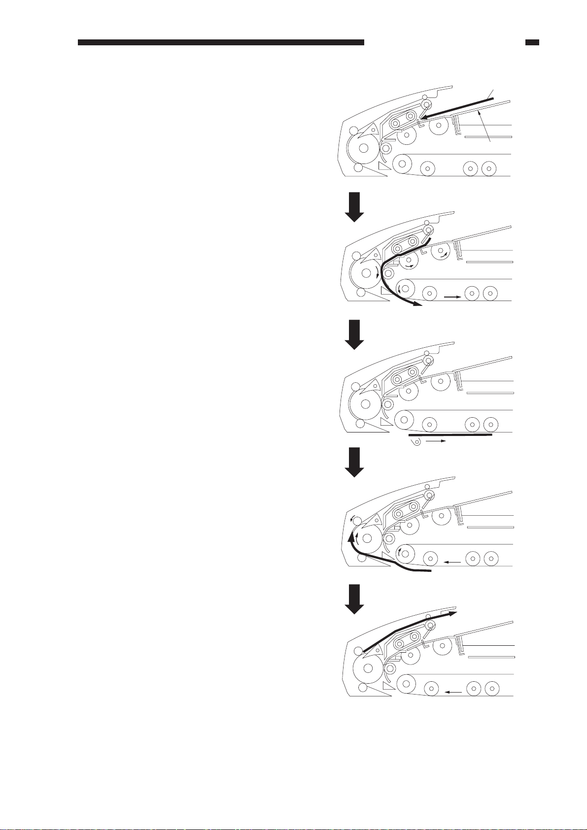
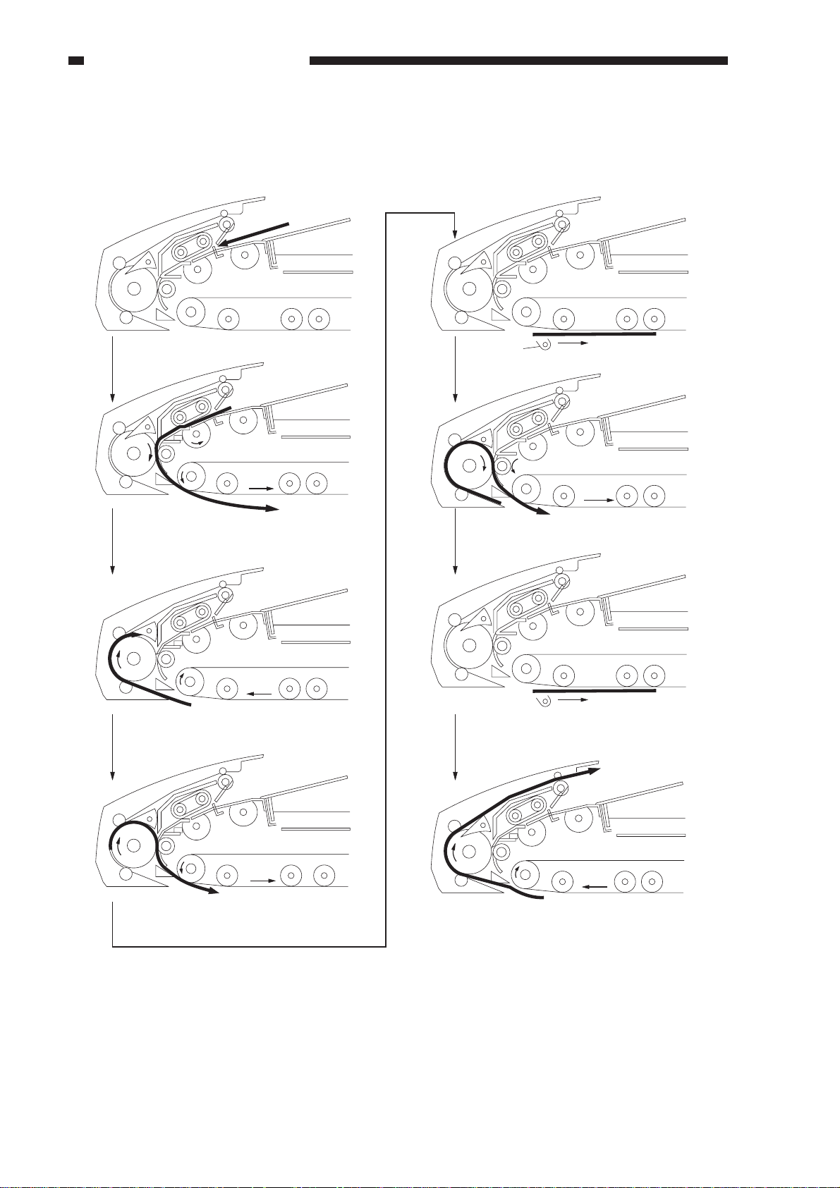
D. Picking Up Originals
1. Outline
The machine picks up originals in either of the following two ways, each characterized by its
own method:
1. Top pick-up (starting with the top of a stack of originals; top separation)
2. Bottom pick-up (starting with the bottom of originals; bottom separation)
In bottom pick-up mode, the last page of the stack of originals on the original tray is picked up
first; on the other hand, in top pick-up mode, the first page will be picked up first.
Top pick-up mode
Figure 2-213
Bottom pick-up mode
Figure 2-214
COPYRIGHT © 1998 CANON INC. CANON DADF-A1 REV.0 DEC. 1998 PRINTED IN JAPAN (IMPRIME AU JAPON)
2-17
Page 36

CHAPTER 2 BASIC OPERATION
2. Configuring the Pick-Up Assembly
The construction of the pick-up assembly is changed by the pick-up motor (M1). When the pickup motor rotates clockwise, the construction will be made ready for bottom pick-up mode; when the
motor rotates counterclockwise, on the other hand, the assembly will be made ready for top
separation.
When the pick-up motor starts to rotate clockwise, the arm on the pick-up roller shaft transmits its
drive to the original guide and the switching arm. In response, the original guide moves up; the rear
and the front of the separation belt operating in connection with the switching arm move down to
switch the construction of the pick-up assembly for bottom pick-up mode.
When the pick-up motor starts to rotate counterclockwise, the arm on the pick-up roller shaft
transmits its drive to the original guide and the switching arm. In response, the original guide moves
downward. On the other hand, the rear and the front of the separation belt operating in connection
with the switching arm moves upward to change the construction of the pick-up assembly for top
pick-up mode.
DADF controller PCB
Original guide
Separation belts
Figure 2-215 Bottom Pick-Up Mode
Switching
arm
DADF controller PCB
Original guide
Pick-up motor
(M1)
M1
Arm
Pick-up motor
(M1)
M1
2-18
Separation belts
Switching
arm
Arm
Figure 2-216 Top Separation Mode
COPYRIGHT © 1998 CANON INC. CANON DADF-A1 REV.0 DEC. 1998 PRINTED IN JAPAN (IMPRIME AU JAPON)
Page 37

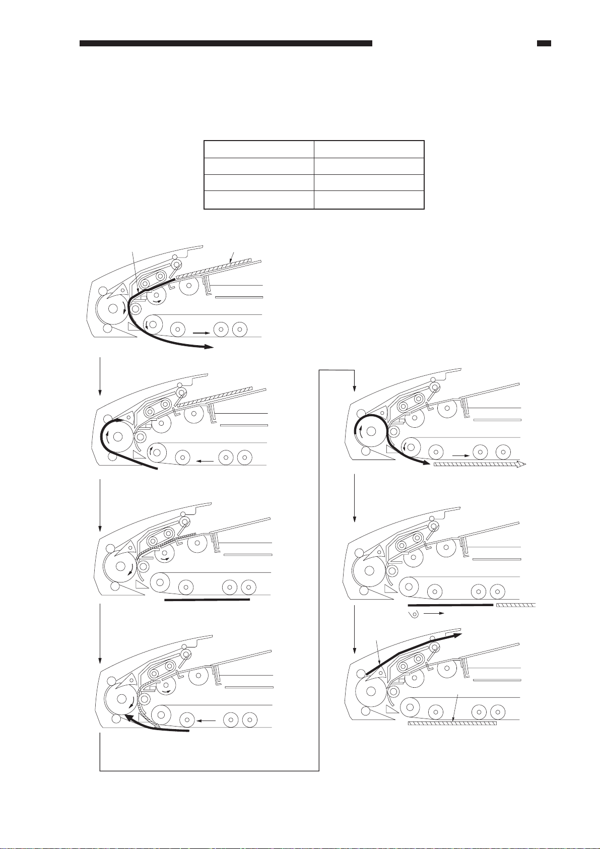
3. Bottom Pick-Up Mode
Arch
Registration roller
a. Operation
When the Copy Start key is pressed while
originals are set on the originals tray, the
following takes place:
1) Pick-Up Separation
The pick-up stopper plate is brought down
to move down the paper retaining plate on
the stack of originals, and the last page of
the stack is picked up.
Note that, after pick-up, the original is
moved between the separation belt and the
feeding roller to prevent double feeding.
CHAPTER 2 BASIC OPERATION
Paper retaining plate
Separation belt
Paper stopper plate
Feeding roller
Caution:
The paper retaining plate is always
brought down when picking up the first
original. For the second and subsequent
originals, the retaining plate is brought
down only when pick-up fails because of
slips (of the pick-up roller) or the like
(i.e., the pick-up sensor S7 does not
detect an original within 500 msec after
the pick-up sensor has turned on) so as to
improve feeding performance.
2) Arching
The original is butted against the
registration roller so that it arches.
Pick-up sensor (S7)
Figure 2-217
COPYRIGHT © 1998 CANON INC. CANON DADF-A1 REV.0 DEC. 1998 PRINTED IN JAPAN (IMPRIME AU JAPON)
Figure 2-218
2-19
Page 38

CHAPTER 2 BASIC OPERATION
3) Feeding
The feeding belt, registration roller, and
feeding roller are rotated to move the
original to the copyboard glass.
Feeding roller
4) Picking Up the 2nd Original
When the original reaches a specific point
on the copyboard glass, the copier’s
scanner starts to move forward. At the
same time, the second original is picked up
(if of small size).
Small size
Large size
A5,B5,B5R,A4,A4R
STMT,LTR,LTRR
B4,A3,LGL
279mm×432mm(11"×17")
Registration roller
Figure 2-219
Edged out by
the registration roller
Figure 2-220
Feeding belt
Scanner
Table 2-205
Caution:
In case of small-size originals, the second
and subsequent originals are “edged out”
by the registration roller so as to reduce
feeding time.
2-20
COPYRIGHT © 1998 CANON INC. CANON DADF-A1 REV.0 DEC. 1998 PRINTED IN JAPAN (IMPRIME AU JAPON)
Page 39

CHAPTER 2 BASIC OPERATION
b. Sequence of Operations (A4, 2 originals, bottom pick-up)
Original set Copy Start key ON
Pick-up sensor
Registration
paper sensor
Reversal sensor
Delivery sensor 1
Pick-up motor
Feeder motor
Belt motor
Clutch
Paper stopper
plate solenoid
Paper retaining
plate solenoid
Brake
(S7)
(S3)
(S8)
(S6)
(M1)
(M2)
(M3)
(CL)
(SL1)
(SL2)
(BK)
Original
picked up
Original fed
Arching
Scanner started/
2nd sheet picked up
Fed/
Delivered
CW CCW
CW
CCW
Scanner
started
CWCCWCW
Low-speed
Feeding belt CW rotation
Feeding belt CCW rotation
Table 2-221
COPYRIGHT © 1998 CANON INC. CANON DADF-A1 REV.0 DEC. 1998 PRINTED IN JAPAN (IMPRIME AU JAPON)
2-21
Page 40

CHAPTER 2 BASIC OPERATION
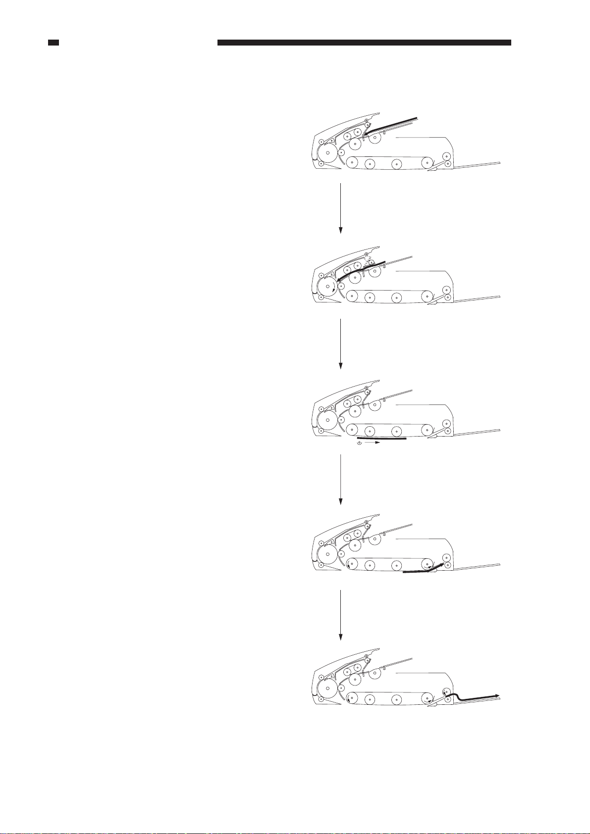
4. Top Pick-Up Mode
a. Operation
When top pick-up mode is executed with
originals on the original tray, the following will
take place:
1) Pick-Up Separation
The paper stop plate is brought down, and
the paper retaining plate is moved down to
the stack of originals; then, the first page of
the stack is picked up.
After pick-up, the original is fed between
the separation belt and the feeding roller to
prevent double feeding. (The direction of
rotation of the separation belt and the
feeding roller is the opposite of the
direction in bottom pick-up mode.)
Separation belt
Paper
retaining plate
Paper stopper plate
Feeding roller
Pick-up sensor
Figure 2-222
1st page of the stack
2) Arching
The original is butted against the
registration roller so that it arches.
Arching
Registration roller
Figure 2-223
2-22
COPYRIGHT © 1998 CANON INC. CANON DADF-A1 REV.0 DEC. 1998 PRINTED IN JAPAN (IMPRIME AU JAPON)
Page 41

3) Feeding
Registration roller
Feeding roller
Feeding belt
Edged out by
the registration roller.
Scanner
The feeding belt, registration roller, and
feeding roller are rotated to move the
original to the copyboard glass.
4) Picking Up the 2nd Original
When the original reaches a specific
position on the copyboard glass, the
copier’s scanner starts to move forward. At
the same time, the 2nd original is picked up
(if of small size).
In the case of a large-size original, the 2nd
original is picked up after delivery of the
first original.
CHAPTER 2 BASIC OPERATION
Figure 2-224
Figure 2-225
COPYRIGHT © 1998 CANON INC. CANON DADF-A1 REV.0 DEC. 1998 PRINTED IN JAPAN (IMPRIME AU JAPON)
2-23
Page 42

CHAPTER 2 BASIC OPERATION
b. Sequence of Operations (A4, 2 originals, top pick-up mode)
Copy Start key ON
Pick-up sensor
Registration
paper sensor
Delivery sensor 2
Pick-up motor
Feeder motor
Belt motor
Clutch
Brake
Stamp solenoid
Paper retaining
plate solenoid
Stopper plate
solenoid
1st original picked up, fed
(S7)
(S3)
(S7)
(M1)
(M2)
(M3)
CW CCW CCW CCW
(CL)
(BK)
(SL4)
(SL2)
(SL1)
The pick-up motor rotates in the direction opposite to the direction in copying mode.
The feeding belt rotates clockwise.
CW
CCW
The feeding belt rotates counterclockwise.
Low speed
Scanner started,
2nd original picked up
2nd original fed
Low speed Low speed
Scanner
forward
Figure 2-226
2-24
COPYRIGHT © 1998 CANON INC. CANON DADF-A1 REV.0 DEC. 1998 PRINTED IN JAPAN (IMPRIME AU JAPON)
Page 43

E. Reversal
Picking up for the 1st side.
1. Operation
Reversal is executed only in bottom pickup mode; it may be either from the first side to
the second side, or from the second side to the
first side. (Since the same mechanism is
involved, the discussions herein will be on
reversal from the first side to the second side.)
1) Picking Up for the 1st Side
An original is moved from the original tray
to the copyboard glass.
2) Reversal/Feeding
The feeding belt is rotated
counterclockwise to reverse/feed the
original on the copyboard glass.
CHAPTER 2 BASIC OPERATION
Figure 2-227
3) Reversal/Delivery Switching
The paper deflecting solenoid (SL3) is
turned on to open the paper deflecting plate
so that the original is moved back to the
copyboard glass, reversing the original.
When the second side of the original is set
on the copyboard glass, the scanner starts
to move forward.
While the scanner is moving in reverse, the
original is reversed once again so that its
first side is set on the copyboard glass.
When the 1st side of the original has been
copied, the original is moved for delivery.
Paper deflecting
plate
Reversing from the 1st side to the 2nd side.
Figure 2-228
COPYRIGHT © 1998 CANON INC. CANON DADF-A1 REV.0 DEC. 1998 PRINTED IN JAPAN (IMPRIME AU JAPON)
Figure 2-229
2-25
Page 44

CHAPTER 2 BASIC OPERATION
2. Sequence of Operations (reversal)
Pick-up sensor
Registration
paper sensor
Reversal sensor
Delivery sensor 1
Pick-up motor
Feeding motor
Belt motor
Paper deflecting
plate solenoid
Clutch
Brake
1st side picked up
(S7)
(S3)
(S8)
(S6)
(M1)
(M2)
(M3)
(SL3)
(CL)
(BK)
1st side
1st side reversed
copied
CCW CCW CCWCW CW
2nd side
copied
Low speed Low speed
Reversed/fed
CW : The feeding belt rotates CW.
CCW : The feeding belt rotates CCW.
3rd side
copied
Figure 2-230
2-26
COPYRIGHT © 1998 CANON INC. CANON DADF-A1 REV.0 DEC. 1998 PRINTED IN JAPAN (IMPRIME AU JAPON)
Page 45

F. Reduced Page Composition
1st original
4th original
3rd original
2nd original
Delivery/reversing roller
1st original
Feeding belt
1. Operation
In reduced page composition mode,
operations differ between bottom pick-up and
top pick-up.
When a mode is picked up and the Copy
Start Key is pressed, pick-up operation takes
place as follows:
The originals are picked up starting with
the last original, requiring reordering. The
machine takes advantage of its reversing
mechanism to reorder originals.
2. Bottom Pick-Up Mode
1) Picking Up the 1st Original
The 1st original is picked up, and is placed
on the copyboard glass. For details, see D3 “Pick-Up in Bottom Pick-Up Mode” on
p. 2-19.
CHAPTER 2 BASIC OPERATION
Figure 2-231
2) Feeding the 1st Side
The feeding belt is rotated clockwise to
move the original on the copyboard glass
to the delivery/reversing roller.
Figure 2-232
COPYRIGHT © 1998 CANON INC. CANON DADF-A1 REV.0 DEC. 1998 PRINTED IN JAPAN (IMPRIME AU JAPON)
2-27
Page 46

CHAPTER 2 BASIC OPERATION
3) Reversing the 1st Original/Delivery
Switching
The paper deflecting solenoid (SL3) is
turned on to open the paper deflecting plate
so that the 1st original is moved back to the
copyboard glass.
4) Separating the 2nd Original/Feeding the
1st Original
The paper deflecting plate solenoid (SL3)
is turned on to open the paper deflecting
plate.
The 2nd original is picked up, and is
stopped as the registration roller. At the
same time, the feeding belt is rotated
clockwise to move the 1st original to the
delivery/reversing roller.
Paper deflecting plate
Figure 2-233
2nd original
Paper deflecting
plate
Delivery/reversing roller
1st original
Registration roller
1st original
Feeding belt
5) Feeding the 1st and 2nd Originals
Simultaneously
The clutch (CL) is turned on, and the
difference in speed between the delivery/
reversing roller and the feeding belt is
eliminated, thereby feeding two originals
simultaneously.
At this time, the order of originals is
changed, and the sheet-to-sheet distance is
adjusted while making a width of overlap.
Figure 2-234
Delivery/reversing roller
Figure 2-235
Feeding belt
2-28
Overlap
Figure 2-236
COPYRIGHT © 1998 CANON INC. CANON DADF-A1 REV.0 DEC. 1998 PRINTED IN JAPAN (IMPRIME AU JAPON)
Page 47

6) Adjusting the Sheet-to-Sheet Distance
The clutch is turned off, and the feeding
belt is rotated slowly counterclockwise,
eliminating the overlap of two originals
and, as a result, adjusting the sheet-tosheet distance.
7) Feeding
CHAPTER 2 BASIC OPERATION
Feeding belt
After the sheet-to sheet distance between
two originals is adjusted to a specific value,
the clutch (CL) is turned on to eliminate the
difference in speed between the delivery/
reversing roller and the feeding belt; then,
the two originals are moved to the
copyboard glass.
Delivery/reversing roller
Delivery/reversing roller
Sheet-to-sheet distance
Figure 2-237
Feeding belt
Sheet-to-sheet distance
Figure 2-238
8) Delivering the 1st Original
After copying, the feeding belt is rotated
clockwise slowly, and the 1st original is
pulled by the delivery/reversing roller and
delivered.
Delivery/reversing
roller
1st original
Feeding belt
2nd original
Reference:
At this time, the leading edge of the 2nd
original is moved to and stopped at the
Figure 2-239
index on the horizontal size plate.
COPYRIGHT © 1998 CANON INC. CANON DADF-A1 REV.0 DEC. 1998 PRINTED IN JAPAN (IMPRIME AU JAPON)
2-29
Page 48

CHAPTER 2 BASIC OPERATION
9) Separating the 3rd Original
The 3rd original is picked up and stopped
at the registration roller.
10) Feeding the 2nd Original
The feeding belt is rotated clockwise
slowly to move the 2nd original to the
delivery/reversing roller.
3rd original
Registration roller
Figure 2-240
Delivery/resign roller
Feeding Belt
11) Delivering the 2nd Original and Picking
Up the 3rd Original
The clutch (CL) is turned on to eliminate
the difference in speed between the
delivery/reversing roller and the feeding
roller; the 2nd original is delivered, and the
3rd original is picked up and stopped on
the copyboard glass.
The rest is the same as the operations
starting with step 1; if no more original
(3rd, 4th) exists, the 2nd original is
delivered after delivering the 1st original.
2nd original
Figure 2-241
2nd original
Feeding belt
3rd original
Delivery/reversing roller
Figure 2-242
1st original
2-30
2nd Original
Figure 2-243
COPYRIGHT © 1998 CANON INC. CANON DADF-A1 REV.0 DEC. 1998 PRINTED IN JAPAN (IMPRIME AU JAPON)
Page 49

CHAPTER 2 BASIC OPERATION
3. Sequence of Operations (reduced page composition mode; bottom pick-up)
Pick-up sensor
Registration
paper sensor
Reversal sensor
Delivery sensor 1
Pick-up motor
Feeder motor
Belt motor
Clutch
Brake
Paper deflecting
plate solenoid
(SL3)
(S7)
(S3)
(S8)
(S6)
(M1)
(M2)
(M3)
(CL)
(BK)
1st original
picked up
CCW CCW CCW CCW CCW CCWCW CW CW CWCW
1st original reversed 2nd/1st original fed Copied
Sheet-to-sheet distance adjustment
Low-speed rotation.
The feeding belt rotates clockwise.
CW
The feeding belt rotates counterclockwise.
CCW
1st/2nd original delivered, 3rd original
picked up, 4th original, separated
Figure 2-244
COPYRIGHT © 1998 CANON INC. CANON DADF-A1 REV.0 DEC. 1998 PRINTED IN JAPAN (IMPRIME AU JAPON)
2-31
Page 50

CHAPTER 2 BASIC OPERATION
4. Top Pick-Up
In top pick-up mode, the originals are
picked up starting with the top sheet, not
requiring reordering of the originals unlike
bottom pick-up mode.
1) Picking Up the 1st Side
The 1st original is picked up and stopped
on the copyboard glass. For details of pick-
up operation, see D-4 “Top Pick-UP” on
p. 2-22.
2) Positioning the 1st Side Original/Feeding
the 2nd Side Original
The 1st original is moved back to adjust the
sheet-to-sheet distance. Further, two
originals are moved simultaneously and
stopped at specific positions.
2nd original
1st original
Figure 2-245
3) Feeding the 1st Side and 2nd Side
Originals Simultaneously
The clutch (CL) is turned on to eliminate
the difference in speed between the
delivery/reversing roller an the feeding
belt, and two originals are fed
simultaneously.
Figure 2-246
Figure 2-247
2-32
COPYRIGHT © 1998 CANON INC. CANON DADF-A1 REV.0 DEC. 1998 PRINTED IN JAPAN (IMPRIME AU JAPON)
Page 51

CHAPTER 2 BASIC OPERATION
4) Delivering the 1st and 2nd Originals
When the original has been read, the
feeding belt is rotated counterclockwise,
and the 1st and 2nd originals are delivered.
If there are 3rd and 4th originals, pick-up
is started.
Figure 2-248
5 Sequence of Operations (reduced page composition; top pick-up)
Copy Start key ON
Pick-up sensor
Registration
paper sensor
Delivery sensor 2
Pick-up motor
Feeder motor
Belt motor
Clutch
Brake
Paper retaining
solenoid
Delivery motor
1st original picked up/fed
(S7)
(S3)
(M1)
(M2)
(M3)
CW CWCCW CCW CCW CCW
(CL)
(BK)
(SL2)
(M5)
The pick-up motor rotates in the direction opposite of copying mode.
CW
The feeding belt rotates clockwise.
CCW
The feeding belt rotates counterclockwise.
Low speed
2nd original picked up/fed
Low speed Low speed
Scanner started
Low speed
Delivered
Low speed
Figure 2-249
COPYRIGHT © 1998 CANON INC. CANON DADF-A1 REV.0 DEC. 1998 PRINTED IN JAPAN (IMPRIME AU JAPON)
2-33
Page 52

CHAPTER 2 BASIC OPERATION
G. Delivery
1. Outline
The machine delivers originals in either of the following two modes:
1. Bottom pick-up mode
2. Top pick-up mode
In the case of bottom pick-up mode, the machine delivers the original to the original tray; in the
case of top pick-up mode, it delivers the original to the original delivery tray.
Original tray
Figure 2-250 Bottom Pick-Up Mode
Original delivery tray
Figure 2-251 Top Pick-up Mode
2-34
COPYRIGHT © 1998 CANON INC. CANON DADF-A1 REV.0 DEC. 1998 PRINTED IN JAPAN (IMPRIME AU JAPON)
Page 53

Delivery/reversing roller
Feeding roller
Reversal sensor (S8)
Paper deflecting plate
Original tray
2. Bottom Pick-Up Mode Delivery
a. Operation
The machine delivers an original on the
copyboard glass to the original tray as follows:
1) Feeding Belt Delivery
The feeding belt is rotated clockwise to
move the original from the copyboard
glass for delivery.
CHAPTER 2 BASIC OPERATION
Feeding belt
Scanner
Figure 2-252
2) Delivery/Reversing Roller Delivery
Reference:
When the leading edge of an original is
moved about 15 mm from the reversal
sensor (S8), the feeding belt starts to
rotate counterclockwise to be ready for
the next pick-up operation.
3) Delivery/Reversal Switching
The original fed by the feeding belt is
moved farther between the delivery/
reversing roller and the feeding roller. In
the case of a small-size original, two
originals are picked up simultaneously.
The paper deflecting plate solenoid (SL3)
is off and, therefore, the paper deflecting
plate remains closed, moving the original
to the original tray as a result.
The next original is picked up and moved
to the copyboard glass.
Figure 2-253
Figure 2-254
COPYRIGHT © 1998 CANON INC. CANON DADF-A1 REV.0 DEC. 1998 PRINTED IN JAPAN (IMPRIME AU JAPON)
2-35
Page 54

CHAPTER 2 BASIC OPERATION
4) Original Tray Delivery
When the trailing edge of an original
leaves the delivery roller, the rotation of
the feeder motor switches to low speed,
slowly delivering the original.
Scanner
Figure 2-255
b. Sequence of Operations (large-size and mix size mode; 2nd original pick-up/delivery)
Pick-up sensor
Registration
paper sensor
Reversal sensor
Delivery sensor 1
Pick-up motor
Feeder motor
Belt motor
Clutch
Brake
(S7)
(S3)
(S8)
(S6)
(M1)
(M2)
(M3)
(CL)
(BK)
1st original
deliveried
2nd original picked up,
2nd original separated
Arching
CCW CW
2nd original
copied
2nd original delivered
Figure 2-256
Low speed
CW
The feeding belt rotates clockwise.
CCW
The feeding belt rotates couuterclockwise.
2-36
COPYRIGHT © 1998 CANON INC. CANON DADF-A1 REV.0 DEC. 1998 PRINTED IN JAPAN (IMPRIME AU JAPON)
Page 55

CHAPTER 2 BASIC OPERATION
c. Sequence of Operations (small size; continuous pick-up/delivery)
Pick-up sensor
Registration
paper sensor
Reversal sensor
Delivery sensor
Pick-up motor
Feeder motor
Belt motor
Clutch
Brake
Scanner forward/
3rd original separated
2nd original copied
(S7)
(S3)
(S8)
(S6)
(M1)
(M2)
(M3)
(CL)
(BK)
2nd original delivered/
3rd original picked up
CW CWCCW CCW
Scanner moved forward/
4th original separated
3rd original copied
3rd original delivered/
4th original picked up
The feeding belt rotates clockwise.
CW
The feeding belt rotates counterclockwise.
CCW
Figure 2-257
d. Sequence of Operations (small size, delivery)
Staggered for delivery Original delivered/separated
Pick-up sensor
Registration
paper sensor
Reversal sensor
Delivery sensor
Pick-up motor
Feeder motor
Belt motor
Clutch
Brake
Paper stopper
plate solenoid
(S7)
(S3)
(S8)
(S6)
(M1)
(M2)
(M3)
(CL)
(BK)
(SL1)
CW CCW
Copied
Low speed
The feeding belt rotates clockwise.
CW
The feeding belt rotates counterclockwise.
CCW
Figure 2-258
COPYRIGHT © 1998 CANON INC. CANON DADF-A1 REV.0 DEC. 1998 PRINTED IN JAPAN (IMPRIME AU JAPON)
2-37
Page 56

CHAPTER 2 BASIC OPERATION
3. Top Pick-Up Mode Delivery
a. Operation
The machine delivers the original on the
copyboard tray as follows:
If a stamp command (in fax mode) arrives
from the copier, the machine puts a stamp
marking in the middle of delivery.
1) Feeding the 1st Original
The feeding belt is rotated
counterclockwise to feed the 1st original
about 30 mm (to maintain the sheet-to-
sheet distance from the 2nd original).
1st original
Figure 2-259
2) Delivering the 1st Original/Picking Up the
2nd Original
The clutch (CL) is turned on to eliminate
the difference in speed between the
delivery/reversing roller and the feeding
belt; the 1st original is moved for delivery,
and the 2nd original is picked up.
3) Delivery to the Original Delivery Tray
While the trailing edge of the original is
moved to the original delivery tray, the
delivery motor (M5) switches to low speed
to deliver the original slowly.
2nd original
1st original
Figure 2-260
2-38
Original delivery tray
Figure 2-261
COPYRIGHT © 1998 CANON INC. CANON DADF-A1 REV.0 DEC. 1998 PRINTED IN JAPAN (IMPRIME AU JAPON)
Page 57

CHAPTER 2 BASIC OPERATION
b. Sequence of Operations (small size, pick-up/delivery; w/ stamp marking)
Pick-up sensor
Registration
paper sensor
Delivery sensor 2
Pick-up motor
Feeding motor
Belt motor
Clutch
Brake
Stamping solenoid
Paper holding
plate solenoid
Delivery motor
(S7)
(S3)
(M1)
(M2)
(M3)
(CL)
(BK)
(SL4)
(SL2)
(M5)
Scanner started/
2nd original picked up
The pick-up motor rotates in the direction opposite of copying mode.
The feeding belt rotates clockwise.
CW
CWW
The feeding belt rotates counterclockwise.
1st original moved to
stamping position
Moved for 20 mm
CCW CCW CCW
Low speed
2nd original
moved
Low speed
Scanner started/
3rd original picked up
3rd original
moved to
stamping
position
Moved for 20 mm
Figure 2-262
c. Sequence of Operations (small size, pick-up/delivery; w/o stamp marking)
Pick-up sensor
Registration
paper sensor
Delivery sensor 2
Pick-up motor
Feeder motor
Belt motor
Clutch
Brake
Stamping
solenoid
Paper retaining
solenoid
(SL4)
(SL2)
Delivery motor
Scanner started/
2nd original picked up
(S7)
(S3)
(M1)
(M2)
(M3)
(CL)
(BK)
(M5)
2nd original
moved
Low speed
CCW CCW
Low speed Low speed
Scanner started/
3rd original pick-up
3rd original moved/
1st original delivered
Low speed
CCW CCW
The pick-up motor rotates in the position opposite of copying mode.
CW
The feeding belt rotates clockwise.
CWW
The feeding belt rotates counterclockwise.
Figure 2-263
COPYRIGHT © 1998 CANON INC. CANON DADF-A1 REV.0 DEC. 1998 PRINTED IN JAPAN (IMPRIME AU JAPON)
2-39
Page 58

CHAPTER 2 BASIC OPERATION
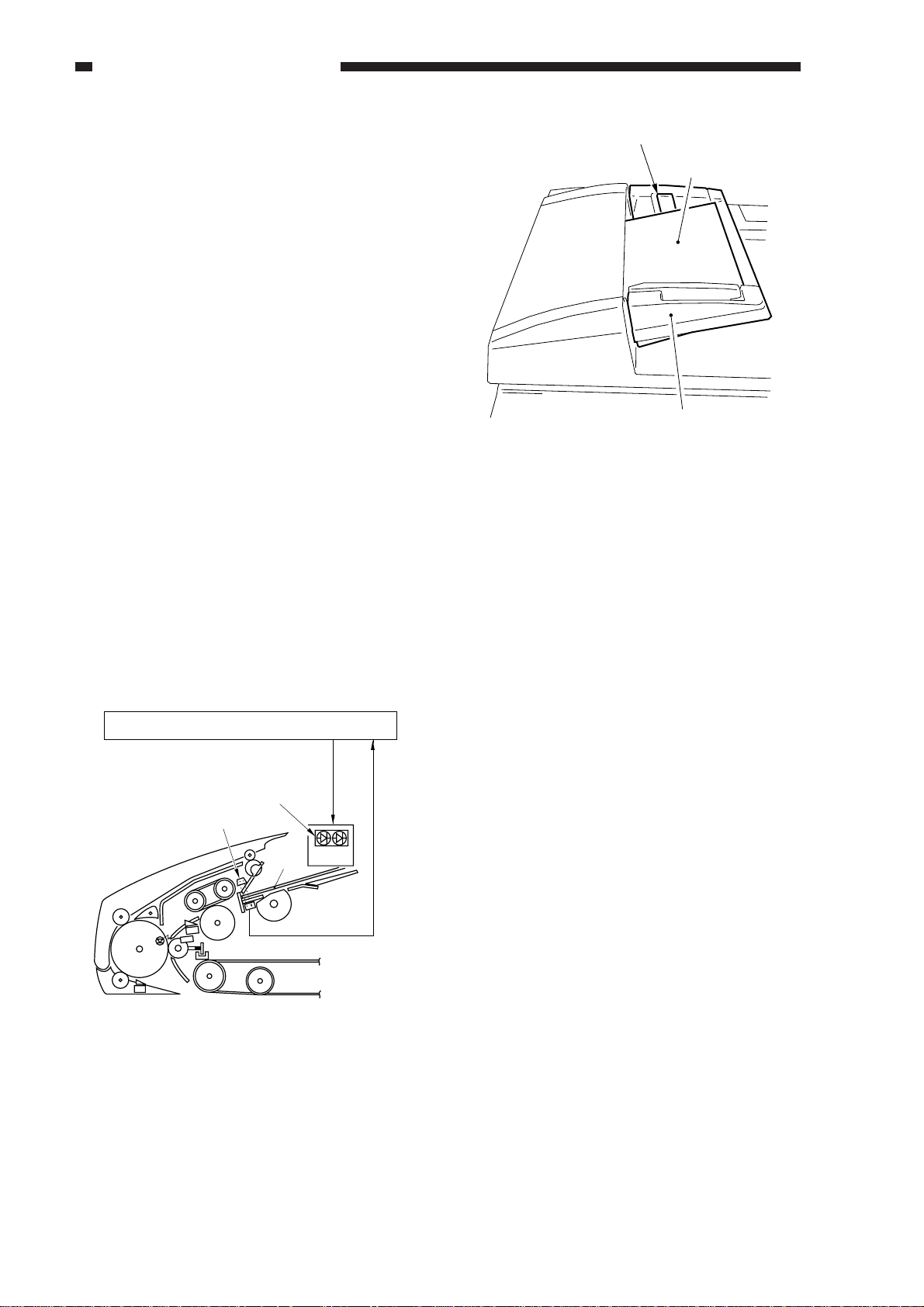
H. Stamping Function
1. Outline
The machine is equipped with a stamping
function, which operates only in fax mode. The
stamping mechanism operates when memory
transmission or direct transmission is selected.
A stamp marking is put on originals in
response to a command from the copier; the
stamping solenoid (SL4) is driven to place a
spot (about 3 mm in diameter) on originals.
A marking is on the face of each original as
follows:
Mode
Single-sided original
mode
Double-sided
original mode
Reduced page
compositionmode
On each original
On 1st side
On each original
Position
The stamp marking is placed as shown:
Print side
Feeding direction
Center of the original
50 mm
(approx.)
20 mm
(approx.)
Figure 2-264
Table 2-206
2-40
COPYRIGHT © 1998 CANON INC. CANON DADF-A1 REV.0 DEC. 1998 PRINTED IN JAPAN (IMPRIME AU JAPON)
Page 59

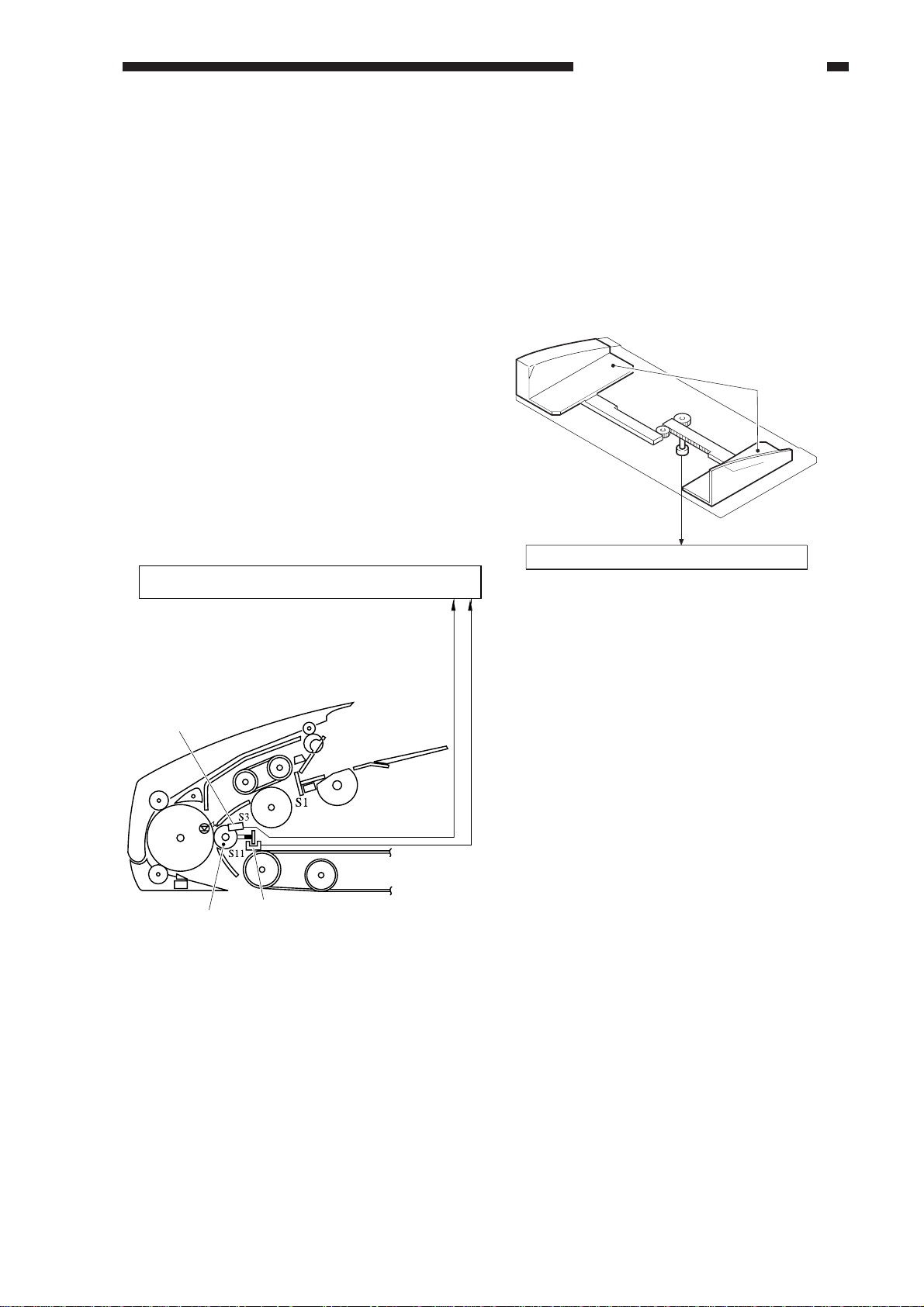
2. Operation
Stamping is initiated by stopping delivery
operation in the middle.
After the start of delivery operation, the
original is moved about 20 mm from the point
at which the delivery sensor 2 (S6) detects the
leading edge. When the original is stopped, the
DADF controller PCB generates the stamp
solenoid drive signal (SMPSL) to drive the
stamp solenoid (SL4), causing the stamp face
mounted to the tip of a plunger to hit against the
original.
Stamping solenoid (SL4)
CHAPTER 2 BASIC OPERATION
SMPSL
Stamp
Fax original
Delivery sensor 2 (S12)
DADF
controller
PCB
Figure 2-265
Reference:
A brand new stamp is good for stamping
about 7,000 (reference value) originals.
COPYRIGHT © 1998 CANON INC. CANON DADF-A1 REV.0 DEC. 1998 PRINTED IN JAPAN (IMPRIME AU JAPON)
2-41
Page 60

CHAPTER 2 BASIC OPERATION
3. Sequence of Operations
Belt motor
(M3)
Delivery feeding
Original length
Feeding about 20mm
(approx.equivalent)
Stamping
Delivery
tray delivery
Delivery sensor 2
Stamping solenoid
Delivery motor
(S12)
(SL4)
Low speed
(M5)
Figure 2-266
2-42
COPYRIGHT © 1998 CANON INC. CANON DADF-A1 REV.0 DEC. 1998 PRINTED IN JAPAN (IMPRIME AU JAPON)
Page 61

CHAPTER 2 BASIC OPERATION
I . Controlling the Pick-Up Motor
1. Outline
Figure 2-267 is a block diagram of the pick-up motor.
The feeder motor is a DC motor. The microprocessor (Q1) on the DADF controller PCB sends
to the drive circuit the pick-up motor drive signal (SMON), pick-up motor rotation direction signal
(SDIR), and pick-up motor rotation speed control signal (SMPWM).
In response, the drive circuit drives the pick-up motor according to these three signals.
The control circuit is not equipped with a circuit used to provide the microprocessor (Q1) with
feed back, indicating the state of pick-up rotation. As such, the pick-up motor rotation speed control
signal (SMPWM) remains constant at all times, and no correction is made when the rotation speed of
the pick-up motor fluctuates because of an external force.
DADF controller PCB
Pick-up motor
Q1
CPU
SMON
SDIR
SMPWM
Drive
circuit
J12-1
M1
J12-2
Figure 2-267
COPYRIGHT © 1998 CANON INC. CANON DADF-A1 REV.0 DEC. 1998 PRINTED IN JAPAN (IMPRIME AU JAPON)
2-43
Page 62

CHAPTER 2 BASIC OPERATION
2. Relationship Between the Pick-UP Motor Drive Signal (SMON), Pick-Up Motor
Rotation Direction Signal (SDIR), and Pick-Up Motor Rotation Speed Control
Signal (SMPWM) and the Operation of the Pick-Up Roller
Belt motor drive
signal (SMON)
"1"
"1"
"1"
"1"
"0"
Belt motor
rotation direction
signal(SDIR)
"1"
"1"
"0"
"0"
"1" / "0"
Belt motor rotation
speed control signal
(SMPWM)
Pulses
"0"
Pulses
"0"
"1" / "0"
Table 2-207
Pick-up roller operation
The pick-up roller rotates in copier
mode pick-up direction
(counterclockwise).
The pick-upper roll rotates by
inertia in copier mode pick-up
direction.
The pick-up roll rotates in fax
mode pick-up direction
(clockwise).
The pick-upper roller rotates by
inertia in fax mode pick-up
direction (clockwise).c
The pick-up roller stops.
2-44
COPYRIGHT © 1998 CANON INC. CANON DADF-A1 REV.0 DEC. 1998 PRINTED IN JAPAN (IMPRIME AU JAPON)
Page 63

CHAPTER 2 BASIC OPERATION
J. Controlling the Belt Motor
1. Outline
Figure 2-268 is an outline diagram of the belt motor control circuit.
The belt motor is a DC motor.
The microprocessor (Q1) on the DADF controller PCB sends the belt motor drive signal
(BMON), belt motor rotation direction signal (BDIR), and belt motor rotation speed control signal
(BMPWM) to the drive circuit.
When the belt motor starts to rotate, the belt motor clock sensor (S10) sends the belt motor clock
signal (BCLK1) to the microprocessor (Q1). In response, the microprocessor (Q1) compares the belt
motor clock signal (BCLK1) against the rotation speed stored in memory to vary the belt motor
rotation speed control signal (PMPWM) to make a match, causing the belt motor (M3) to rotate at a
specific speed at all times.
DADF controller PCB
Q1
CPU
BMON
BDIR
BMPWM
BCLK1
Drive
circuit
Figure 2-268
J7-1
J7-2
Belt motor
clock sensor
J9-B4
Belt motor
M3
S10
COPYRIGHT © 1998 CANON INC. CANON DADF-A1 REV.0 DEC. 1998 PRINTED IN JAPAN (IMPRIME AU JAPON)
2-45
Page 64

CHAPTER 2 BASIC OPERATION
2. Relationship Between the Belt Motor Drive Signal (BMON), Belt Motor Rotation
Direction Signal (BDIR), and Belt Motor Rotation Speed Control Signal (BMPWM)
and the Feeding Belt
Belt motor drive
signal (BMON)
"1"
"1"
"1"
"1"
"0"
Belt motor
rotation direction
signal(BDIR)
"1"
"1"
"0"
"0"
"1" / "0"
Belt motor rotation
speed control signal
(BMPWM)
Pulses
"0"
Pulses
"0"
"1" / "0"
Feeding Belt
The feeding belt rotates in pick-up
direction (counterclockwise).
The feeding belt rotates by inertial
in pick-up direction
(counterclockwise).
The feeding belt rotates in copier
mode delivery direction
(clockwise).
The feeding belt rotates by inertial
in copier mode delivery
direction(clockwise).
The feeding belt stops.
Table 2-208
3. Protecting the Belt Motor from Overcurrent
At times, overcurrent can occur because of a specific type of original or state of the machine. To
protect the power supply circuit from extra loads occurring because of continuing overcurrent while
the belt is rotating in pick-up direction, an overcurrent control circuit is provided.
2-46
COPYRIGHT © 1998 CANON INC. CANON DADF-A1 REV.0 DEC. 1998 PRINTED IN JAPAN (IMPRIME AU JAPON)
Page 65

K. Detecting Original Jams
Jam type
Original retraction
Pick-up delay
Registration delay
Sensor type
S1,S7
01H
02H
03H
S3,S7
S7
Description Code
Pick-
up
The sensor S7 does not detect the leading edge of an original
1500 msec after the pick-up motor (M1) has turned on and, in
addition, the sensor S1 does not detect an original.
The sensor S7 does not detect the leading edge of an original
1500 msec after the pick-up motor (M1) has turned on.
The sensor S3 does not detect the leading edge of an original
350 msec after the sensor S7 has detected the leading edge of
an original.
S6
S7
S3
S8
S1
S4
CHAPTER 2 BASIC OPERATION
S14
M4
MS1 MS2
S12
S1 Original tray paper
sensor
S3 Registration paper sensor
S4 Upper cover sensor
S6 Delivery sensor 1
S7 Pick-up sensor
S8 Reversal sensor
S12 Delivery sensor 2
S14 Re-circulation sensor
MS1 DADF switch
MS2 Upper cover switch
Figure 2-269
The timing at which the machine checks for jams is stored in memory in the microprocessor on
the DADF controller PCB, and a jam is detected in terms of the presence/absence of paper at a
specific sensor at the time.
When a jam is detected, the machine communicates the fact to the copier in the form of a code.
(Some copiers show such codes in service mode.)
Table 2-209a
COPYRIGHT © 1998 CANON INC. CANON DADF-A1 REV.0 DEC. 1998 PRINTED IN JAPAN (IMPRIME AU JAPON)
2-47
Page 66

CHAPTER 2 BASIC OPERATION
Jam type Sensor type
Double feeding
Pickup
Original leading
edge retreat
Reversal delay 1
Reversal stationary
Reversal delay 2
Reversal
Reversal initial
paper
Reversal pick-up
delay
Reversal pick-up
stationary
S3
S3
S8
S8
S8
S8
S3
S3
Description Code
The sensor S3 remains on even when the 1st original is
placed on the copyboard.
At the start of original pick-up, the sensor S3 does not
detect the leading edge of an original.
At time of original reversal or delivery, the sensor S8 does not
detect the leading edge of an original 140 mm or 225 msec
after the belt motor (M3) has started to rotate clockwise.
At time of original reversal or delivery, the sensor S8 does not
detect the trailing edge of an original after a reversal delay check.
At time of original delivery pick-up, the sensor S8 does not
detect the preceding original 50 mm after the belt motor has
started to rotate counterclockwise. (The original to be delivered
is moved back to the copyboard glass together with the original
picked up).
At time of original reversal, the sensor S8 is on.
At time of original reversal, the sensor S3 does not detect the
leading edge of the original that has been reversed 100 mm or
300 msec after the sensor S8 has detected an original.
The sensor S3 does not detect the trailing edge of an original
'original size + 180 mm' after the sensor S8 has turned on.
06H
08H
11H
12H
13H
20H
21H
23H
Delivery delay
Delivery stationary
DADF open
Upper cover open
Deli-
Jam original
very
Re-circulating lever
idle rotation
(2nd circulation or
later)
Residual original
Double feeding
S6
S6
MS1
MS2
S4
S1
S6,S3
S8,S7
S8
S14
At time of original delivery, the sensor S6 does not detect an
original 100 mm or 250 msec after the sensor S8 has detected
the leading edge of an original.
The sensor S6 does not detect the trailing edge of an original
100 mm or 250 msec after a reversal stationary check.
The DADF is opened while in operation.
The upper cover is opened while the DADF is in operation.
The sensor S1 does not detect the original delivered on the
original tray.
At the start of original pick-up, the sensor S6, S3, or S8
(also S7 if the paper stopper plate is up) is on.
When picking up the 1st original, an original is detected
on the copyboard glass.
For the 2nd circulation or later, the re-circulating lever
rotates idly without coming into contact with an original.
Table 2-209b
41H
42H
81H
82H
83H
84H
88H
89H
2-48
COPYRIGHT © 1998 CANON INC. CANON DADF-A1 REV.0 DEC. 1998 PRINTED IN JAPAN (IMPRIME AU JAPON)
Page 67

CHAPTER 2 BASIC OPERATION
Jam type Sensor type
Delivery failure
DADF open
Deliver y
Upper cover open
Re-circulating
lever idle rotation
S3,S6
MS1
MS2,S4
S13
At time of delivery in bottom separation pick-up mode,
the original fails to stop (e.g., the original that has been
picked up is longer than the original being delivered).
While the copier is at reset because of, for example, the
absence of paper, the DADF is opened.
While the copier is at reset because of, for example, the
absence of paper, the upper cover is opened.
At time of original pick-up, the re-circulating lever fell off
a stack of original.
Description Code
Table 2-209c
Caution
1. Result of Detection
The DADF will stop operation immediately upon detection of a jam shown in Table 2-209.
2. Resetting
For a pick-up delay jam, the machine may be reset by removing the original from the
original tray. For other types of jams, remove the originals from the original tray, remove the
jam from the DADF, and open the DADF.
84H
91H
92H
93H
Reference:
As a rule, detection of a condition for the first original is treated as “improperly placed original”;
jams are identified starting with the detection of a condition for the second and subsequent
originals.
COPYRIGHT © 1998 CANON INC. CANON DADF-A1 REV.0 DEC. 1998 PRINTED IN JAPAN (IMPRIME AU JAPON)
2-49
Page 68

CHAPTER 2 BASIC OPERATION
L. Improper Placement of Originals
Re-circulating lever
S14
M4
S3
S4
S1
S7
Paper stopper plate
S1 Original tray paper sensor
S3 Registration paper sensor
S7 Pick-up sensor
S14Re-circulation sensor
Figure 2-270
An improperly placed original can cause a jam or damage to the original. The machine makes a
check to ensure that all originals are placed properly to prevent jams or damage. The timing of a
check is stored in the microprocessor on the DADF controller, and detection is made in terms of the
presence/absence of paper over a specific sensor.
When the machine detects an improperly placed original, it communicates the fact to its host
copier. (Some copiers show such codes in service mode.)
2-50
COPYRIGHT © 1998 CANON INC. CANON DADF-A1 REV.0 DEC. 1998 PRINTED IN JAPAN (IMPRIME AU JAPON)
Page 69

CHAPTER 2 BASIC OPERATION
Fault Sensor Description DADF operation Code
Re-circulating lever idle
rotation
Pick-up failure
Paper stopper plate
overriding
Count mismatch
Original count
S11
S7
S7
S3
S3
Immediately after the re-circulation motor M4
starts to operate, the re-circulating lever rotates
idly without coming into contact with an original.
The sensor S7 does not detect the leading
edge of an original 1500 msec after the
start of pick-up.
At time of placement of originals, the
originals ride over the paper stopper plate.
The number of originals placed on the
original tray after jam removal is as follows;
see Note:
Original copied
Original placed
on tray
The re-circulating lever does not fall under
the original tray, not enabling detection of
the last original.
Reference
Normally, the original tray can hold as
many as 50 sheets of A5, STMT, A4,
B5, or LTR or 25 sheets of A3, B4,
279x432mm (11"x17"), or LGL.
Stops operation
immediately upon
detection.
The separation belt,
feeding roller, and
pick-up roller stop
operation immediately.
The original moving in
advance is delivered
after the end of
copying; then, the
DADF stops operation.
Stops operation
mmediately upon
detection.
Stops operation
immediately upon
detection.
Stops operation
after counting 100
sheets.
01H
03H
05H
11H
12H
Original extraction
Wrong original size
Wrong original size or
size mix in reduced
page composition mode
S14
S3
S3
The re-circulating lever fell under the original
tray while an original is being processed.
The size of the original that is picked up
is of a non-default size.
1. The original that is picked up is of a type
not supported by reduced page
composition mode.
2. The original that is picked up is of a size
different from the size of the first original.
Table 2-210
Stops operation
immediately upon
detection.
Stops operation
immediately upon
detection.
Stops detection
immediately upon
detection.
13H
14H
15H
COPYRIGHT © 1998 CANON INC. CANON DADF-A1 REV.0 DEC. 1998 PRINTED IN JAPAN (IMPRIME AU JAPON)
2-51
Page 70

CHAPTER 2 BASIC OPERATION
As many as10 originals
are placed on the
original tray.
The 8th original
jams.
(As many as 7 originals
have been copied.)
Error 2
Error 1
Normal
Place 10 originals on the
original tray in initial
condition
As many as 3 originals
are placed on the
original tray.
10 (originals) - 7 (copied) = 3 originals
The 7 originals that
have been copied are
counted, and copying is
resumed with the 8th original.
The originals are counted,
and then the DADF is
stopped.
The 3rd original
jams.
(As many as 2 originals
have been copied.)
As many as 8 originals
are placed on the
original tray.
10 (originals) - 2 (copied) = 8 originals
The originals are counted,
and then copying is resumed
with the 2nd.
When a jam occurs, the host copier remembers how many originals have been copied. The count
is sent to the DADF after jam removal, and the DADF circulates the originals that have been copied;
it then places originals that have not been copied on the copyboard for copying. This is why normal
copying would not be possible if a different number of originals are placed on the original tray after
jam removal.
In the above chart, error 1 will be treated as a condition in which a different number of originals
are placed after jam removal; in such a case, both the DADF and the copier stop operation to indicate
an error. The operation continues, however, for error 2.
1. Resetting
To reset, remove all originals from the original tray, and then place the originals once again.
Some copiers indicate an appropriate message. Be sure to follow such a message when placing the
originals.
In reduced page composition mode, on the other hand, remove the originals from the original
tray, and open the DADF once.
2-52
COPYRIGHT © 1998 CANON INC. CANON DADF-A1 REV.0 DEC. 1998 PRINTED IN JAPAN (IMPRIME AU JAPON)
Page 71

CHAPTER 2 BASIC OPERATION
III. POWER SUPPLY
A. Outline
Figure 2-301 is an outline diagram of the machine’s power supply system.
The machine’s power supply is provide by its host copier with 24 V (24 VP, 24 VL).
24 VP is mainly used for loads, and is cut off when the machine is opened or its upper cover is
opened. The circuit breaker (CB1) operates to cut off the power to protect the circuit in response to
overcurrent.
24 VL is converted by the regulator into 5 V, and is used by the logic system and sensors.
The fuse resistance (R26) melts in response to overcurrent in the circuit, thereby cutting off the
power and protecting the circuit.
Copier
24VP
24VL
RF switch
J2-1
Circuit breaker
Fuse resistance
(R26)
J1-6
(MS1)
(CB1)
J2-3 COM
J2-4 NO
J3-1 COM
Regulator
IC (Q14)
5V
DADF controller PCB
Figure 2-301
Upper cover switch
(MS2)
J3-2 NO
Logic
Solenoid
(SL1 through SL4)
Clutch (CL)
Brake (BK)
Motor (M1, M2, M3, M4)
Sensor (S1 through S14)
Original width detecting
volume (VR)
Indicator LED
(LED101, LED102)
Re-circulation motor (M4)
COPYRIGHT © 1998 CANON INC. CANON DADF-A1 REV.0 DEC. 1998 PRINTED IN JAPAN (IMPRIME AU JAPON)
2-53
Page 72

Page 73

CHAPTER 3
MECHANICAL SYSTEM
I. BASIC CONSTRUCITON ............ 3-1
A. External Covers..........................3-1
B. Switches.....................................3-3
C. Adjusting the DADF Height ........3-5
II. DRIVE SYSTEM .......................... 3-6
A. Removing the Pick-Up
Motor Unit ...................................3-6
B. Removing the Feeder
Motor Unit ...................................3-6
C. Belt Motor ...................................3-7
D. Removing the Clutch Unit ..........3-9
E. Delivery Motor ..........................3-10
III. FEEDING SYSTEM ................... 3-11
A. Pick-Up Roller .......................... 3-11
B. Removing the Separation
Belt Unit.................................... 3-12
C. Feeding Roller Unit.................. 3-12
D. Registration Roller ................... 3-14
E. Delivery/Resersing Roller ........ 3-16
F. Delivery Roller Unit
(bottom pick-up mode).............3-20
G. Delviery Roller Unit
(top pick-up mode)....................3-20
H. Reversing Guide ...................... 3-22
I. Stopper Plate Solenoid ............ 3-24
J. Positioning the Paper Retaining
Plate Solenoid (SL2) ................ 3-24
K. Positioning the Paper Deflecting
Solenoid (SL3) ......................... 3-26
L. Stamp Solenoid........................ 3-26
M. Feeding Belt ............................. 3-28
IV. CLEANING ................................ 3-30
A. Belt Assembly ..........................3-30
B. Sensors .................................... 3-30
C. Separation Flapper .................. 3-33
D. Separation Guide ..................... 3-33
V. FEEDING...................................3-34
A. Pick-Up Drive Assembly .......... 3-34
B. Right Delivery Drive
Assembly..................................3-34
COPYRIGHT © 1998 CANON INC. CANON DADF-A1 REV.0 DEC. 1998 PRINTED IN JAPAN (IMPRIME AU JAPON)
Page 74

Page 75

CHAPTER 3 MECHANICAL SYSTEM
I.
BASIC CONSTRUCTION
A.External Covers
[2]
[1]
[1]Upper cover
[2]Original tray
[3]Body cover
[4]Front cover
Figure 3-101
Remove the covers as shown when
cleaning, inspecting, and repairing the inside of
the machine.
[3]
[4]
4)Go to the rear of the copier, and lift the
DADF upright to remove.
1. Removing the DADF
1)Turn on off the copier.
2)Disconnect the communication cable of
the DADF from the copier.
3)Open the DADF fully.
Figure 3-103
Reference:
The feet of the hinges of the machine are
equipped with a locking mechanism
designed to prevent slippage. When
detaching the machine from the copier,
you must fully open it to disengage its
locks.
Figure 3-102
COPYRIGHT © 1998 CANON INC. CANON DADF-A1 REV.0 DEC. 1998 PRINTED IN JAPAN (IMPRIME AU JAPON)
3-1
Page 76

CHAPTER 3 MECHANICAL SYSTEM
2. Removing the Body Cover
1) Remove the seven mounting screws, and
detach the body cover.
[1]
Figure 3-104
[1]
[1] [1]
2) Remove the two mounting screws [2], and
detach the original tray.
Caution:
The original tray is connected by means
of a cable. Take extra care not to damage
the cable during work.
[2]
[3]
[1]
Figure 3-105
Figure 3-106
[2]
Figure 3-107
3) While avoiding the original tray, detach the
body cover and the front cover.
[1]
3-2
COPYRIGHT © 1998 CANON INC. CANON DADF-A1 REV.0 DEC. 1998 PRINTED IN JAPAN (IMPRIME AU JAPON)
Page 77

CHAPTER 3 MECHANICAL SYSTEM
Copier
DADF
10~100mm
3. Side Guide Lock
The side guide of the machine is equipped
with a side guide lock so that it will not open
farther than 297 mm (A/A3).
If an original longer in width than 297 mm
is used, the side guide lock must be removed
(00 mm max.).
1) Loosen the screw [1], and remove the side
guide lock [2].
Stopper
Plate
Screw
B. Switches
The machine is equipped with two
microswitches (DADF switch MS1 and upper
cover open/closed switch MS2) so that the
machine will not operate when it or its upper
cover is open.
1. Adjusting the DADF Switch (MS1)
1) Remove the body cover.
2) Open and close the DADF, and adjust the
retaining plate [2] so that the DADF switch
(MS1) [1] turns on and off while the
distance from the copyboard glass to the
DADF end is between 10 and 100 mm.
[1]
Figure 3-108
Caution:
When making copies, be sure to adjust
the side guide to the size of the original.
If the side guide is improperly positioned,
the original will tend to move askew.
[2]
Figure 3-109
Figure 3-110
COPYRIGHT © 1998 CANON INC. CANON DADF-A1 REV.0 DEC. 1998 PRINTED IN JAPAN (IMPRIME AU JAPON)
3-3
Page 78

CHAPTER 3 MECHANICAL SYSTEM
2. Upper Cover Switch (MS2)
1) Check to make sure that both upper cover
switches (front, rear) are on when the
upper cover is closed.
3. Mounting the Original Width
Detecting Volume
1) Loosen the two screws [2], and detach the
side guide [1].
[1]
[2]
3) Mount the gear [5].
[5]
Figure 3-113
4) Turn the original width detecting volume
[6] fully in the direction of the arrow; then,
turn it in the opposite direction (equivalent
of half a tooth) so that it is as indicated in
the figure.
Figure 3-111
2) Open the side guide at the rear [3] and the
front [4] fully.
[4]
[3]
Figure 3-112
Half a tooth
[6]
Figure 3-114
3-4
COPYRIGHT © 1998 CANON INC. CANON DADF-A1 REV.0 DEC. 1998 PRINTED IN JAPAN (IMPRIME AU JAPON)
Page 79

CHAPTER 3 MECHANICAL SYSTEM
5) Keeping the original width detecting
volume [6] as in step 4), mount it to the
original tray [7], and fix it in position with
screws [8]; then, connect the connector [9].
[8]
[7]
[9]
[6]
Figure 3-115
6) Mount the side guide lock removed in step
1, and execute adjustments of the original
width detecting volume. (For adjustments,
see p. 5-18.)
C. Adjusting the DADF Height
1) Remove the copier’s rear side plate.
Loosen the locking nut [1], and turn the
height adjusting screw [2] so that the left/
right rear foot is 0.2 ±0.1 mm from the
horizontal size plate of the copyboard
glass.
[1]
[2]
Figure 3-116
2) After making adjustments, check to make
sure that the left and right front rubber feet
are in contact with the copyboard glass.
COPYRIGHT © 1998 CANON INC. CANON DADF-A1 REV.0 DEC. 1998 PRINTED IN JAPAN (IMPRIME AU JAPON)
3-5
Page 80

CHAPTER 3 MECHANICAL SYSTEM
II . DRIVE SYSTEM
A. Removing the Pick-Up
Motor Unit
1) Remove the body cover.
2) Remove the tie-wrap as necessary.
3) Disconnect the connector J12 [2] from the
DADF controller PBC [1].
5) Disconnect the connector [5] of the upper
cover sensor S4.
6) Remove the two mounting screws [6], and
detach the pick-up motor unit [7].
[6]
[5]
[6]
[7]
[1] [2]
Figure 3-201
4) Remove the screw [3], and remove the
cable guide [4].
Figure 3-203
B. Removing the Feeder Motor
Unit
1) Remove the pick-up motor unit.
2) Remove the tie-wrap as necessary.
3) Disconnect the connector J11 [2] from the
DADF controller PCB [1].
3-6
[4]
[3]
[1]
[2]
Figure 3-202
Figure 3-204
COPYRIGHT © 1998 CANON INC. CANON DADF-A1 REV.0 DEC. 1998 PRINTED IN JAPAN (IMPRIME AU JAPON)
Page 81

CHAPTER 3 MECHANICAL SYSTEM
4) Remove the two screws [4], and
disconnect the connector [3] of the feeder
motor clock sensor S9.
[3]
[4]
[4]
Figure 3-205
5) Detach the two drive belts [5], and detach
the feeder motor unit [6].
C. Belt Motor
1. Removing the Belt Motor
1) Remove the DADF from the copier.
2) Remove the feeder motor unit.
3) Remove the tie-wrap as necessary.
4) Disconnect the connectors J6 [1], J7 [3],
and J13 [3] of the DADF controller PCB.
[3] [1] [2]
[5]
[6]
Figure 3-206
Figure 3-207
5) Disconnect the connector [4] of the belt
motor clock sensor (S10).
[4]
Figure 3-208
COPYRIGHT © 1998 CANON INC. CANON DADF-A1 REV.0 DEC. 1998 PRINTED IN JAPAN (IMPRIME AU JAPON)
3-7
Page 82

CHAPTER 3 MECHANICAL SYSTEM
6) Mark the position of the belt motor count
[5] on the DADF with a scriber, and
remove the three screws [6].
[6]
[5]
Figure 3-209
7) Detach the feeding belt drive roller side [8]
of the timing belt [7], and detach the belt
motor unit [5].
2. Making Adjustments
1) Secure the belt motor unit [2] in place with
three screws so that the displacement is 3
±1 mm when the timing belt is pushed
under a force of 3 ±1 mm.
3 1mm
+
50mm (approx.)
[2]
+
200 20g
[1]
[3]
[7]
[5]
Figure 3-210
[8]
The spring gauge must be capable of measuring 600 g or so
(CK-0058).
Figure 3-211
2) Pull the belt tensioner [4] with a force of
500 ± 50 g, and secure it in place with the
screw [5].
+
500 20g
3-8
[4] [5]
The spring must be capable of measuring 600 g or so
(CK-0058).
Figure 3-212
COPYRIGHT © 1998 CANON INC. CANON DADF-A1 REV.0 DEC. 1998 PRINTED IN JAPAN (IMPRIME AU JAPON)
Page 83

CHAPTER 3 MECHANICAL SYSTEM
D. Removing the Clutch Unit
1) Remove the belt unit [1].
2) Detach the drive belt [2].
[1]
[2]
Figure 3-213
3) Remove the E-ring [3].
4) Displace the bush [4], and remove the
clutch unit [5].
Caution:
When mounting the clutch unit, be sure
that the slip stop [6] of the clutch engages
with the stopper [7] of the mount.
[6]
[7]
figure 3-215
[4]
[3]
[5]
Figure 3-214
COPYRIGHT © 1998 CANON INC. CANON DADF-A1 REV.0 DEC. 1998 PRINTED IN JAPAN (IMPRIME AU JAPON)
3-9
Page 84

CHAPTER 3 MECHANICAL SYSTEM
E. Delivery Motor
1) Remove the body cover.
2) Disconnect the three connectors [1].
[1]
4) Disconnect the connector [6], and remove
the two screws [7]; then, detach the
delivery motor [8].
[6]
[8]
[7]
Figure 3-218
Figure 3-216
3) Remove the two screws [2], and free the
cable [4] from the cable retainer [3]; then,
detach the delivery monitor unit [5].
[5]
[3]
[2] [4] [2]
3-10
Figure 3-217
COPYRIGHT © 1998 CANON INC. CANON DADF-A1 REV.0 DEC. 1998 PRINTED IN JAPAN (IMPRIME AU JAPON)
Page 85

CHAPTER 3 MECHANICAL SYSTEM
III. FEEDING SYSTEM
A. Pick-Up Roller
1) Remove the body cover.
2) Remove the two screws [1], and detach the
original tray mount [2].
[1] [2] [1]
4) Remove the two screws [5], and detach the
original inlet guide plate [6].
[6]
[5]
[5]
Figure 3-303
Figure 3-301
3) Remove the screw [3], and detach the
paper retaining solenoid [4].
[4]
[3]
5) Rotate the pick-up roller [7] so that it is as
shown in the figure; then, remove the
screw [8], and detach the pick-up roller.
[8]
[7]
Figure 3-304
Figure 3-302
COPYRIGHT © 1998 CANON INC. CANON DADF-A1 REV.0 DEC. 1998 PRINTED IN JAPAN (IMPRIME AU JAPON)
3-11
Page 86

CHAPTER 3 MECHANICAL SYSTEM
B. Removing the Separation
Belt Unit
1) Remove the body cover.
2) Detach the reversing roller drive belt [1].
[1]
C. Feeding Roller Unit
1) Remove the body cover.
2) Remove the original tray mount.
3) Remove the original inlet guide plate.
4) Remove the separation belt unit.
5) Remove the four screws [5], and detach
the separation guide plate [6].
[5] [6] [5]
Figure 3-305
3) Remove the two screws [2], and detach the
separation belt unit [3] together with the
fixing plate [4].
[3] [2] [4] [2]
Figure 3-307
6) Remove the two screws [8], and detach the
inside guide plate [7].
[8] [7]
[8]
Figure 3-308
3-12
Figure 3-306
COPYRIGHT © 1998 CANON INC. CANON DADF-A1 REV.0 DEC. 1998 PRINTED IN JAPAN (IMPRIME AU JAPON)
Page 87

CHAPTER 3 MECHANICAL SYSTEM
7) Remove the screw [9], and detach the
stopper [10].
[9] [10]
Figure 3-309
8) Remove the E-ring [11], and detach the
idler gear [12].
9) Remove the E-ring [13], and detach the
gear [14] and the timing belt [15]. (Take
care not to drop the pin.)
10) Remove the E-ring [16], and shift the arm
[17] and the gear [18] in the direction of the
arrow.
[16] [17] [18]
Figure 3-311
11) Remove the E-ring [19], and shift the bush
[20] in the direction of the arrow; then,
remove the feeding roller unit [21].
[12]
[11] [15]
[14] [13]
Figure 3-310
[21] [19] [20]
Figure 3-312
COPYRIGHT © 1998 CANON INC. CANON DADF-A1 REV.0 DEC. 1998 PRINTED IN JAPAN (IMPRIME AU JAPON)
3-13
Page 88

CHAPTER 3 MECHANICAL SYSTEM
D. Registration Roller
1) Remove the DADF from the copier.
2) Remove the body cover.
3) Remove the feeding roller unit.
4) Remove the pick-up motor unit.
5) Remove the four screws [2], and detach
the right hinge unit [1].
[2]
7) Remove the screw [5], and detach the
solenoid mount [6].
[6]
[5]
Figure 3-315
8) Remove the spring [7] and the screw [8];
then, detach the arm [9].
[2]
[1]
[2]
Figure 3-313
6) Remove the E-ring [3], and detach the
bush [4].
[4] [3]
[7] [9] [8]
Figure 3-316
3-14
Figure 3-314
COPYRIGHT © 1998 CANON INC. CANON DADF-A1 REV.0 DEC. 1998 PRINTED IN JAPAN (IMPRIME AU JAPON)
Page 89

CHAPTER 3 MECHANICAL SYSTEM
9) Remove the E-ring [10] and the bush [11];
then, detach the link arm shaft [12].
[10] [11] [12]
11) Remove the E-ring [15], tension spring
[16], bush [17], and two screws [18].
[18]
[18]
[17]
[15]
[16]
Figure 3-319
Figure 3-317
10) Remove the two screws [13], and remove
the sensor mount [14].
[14]
[13]
12) Remove the grip ring [19], clock plate
[20], sensor mount [21], and spring [22].
[21]
[22]
[20]
[19]
Figure 3-320
Figure 3-318
COPYRIGHT © 1998 CANON INC. CANON DADF-A1 REV.0 DEC. 1998 PRINTED IN JAPAN (IMPRIME AU JAPON)
3-15
Page 90

CHAPTER 3 MECHANICAL SYSTEM
13) Remove the grip ring [23], tension spring
[24], bush [25], and two screws [26]; then,
detach the registration roller [27].
[25]
[26] [24] [23]
[26]
[27]
E. Delivery/Reversing Roller
1) Remove the DADF from the copier.
2) Remove the body cover.
3) Remove the registration roller.
4) Remove the two E-rings [1], gear [2],
timing belt [3], and bush [4]. (Take care
not to drop the pin.)
Figure 3-321
[3] [1] [2] [1] [4]
Figure 3-322
3-16
COPYRIGHT © 1998 CANON INC. CANON DADF-A1 REV.0 DEC. 1998 PRINTED IN JAPAN (IMPRIME AU JAPON)
Page 91

CHAPTER 3 MECHANICAL SYSTEM
5) Remove the gear [10]. (Take care not to
drop the pin.)
[5]
Figure 3-323
6) Remove the grip ring [6], and remove the
bush [7].
[7]
[6]
Figure 3-324
Reference:
Remove the gear while unlocking it.
Figure 3-323-a
7) Remove the spring [8] and the screw [9];
then, detach the lower guide stopper [10].
[10] [9] [8]
Figure 3-325
COPYRIGHT © 1998 CANON INC. CANON DADF-A1 REV.0 DEC. 1998 PRINTED IN JAPAN (IMPRIME AU JAPON)
3-17
Page 92

CHAPTER 3 MECHANICAL SYSTEM
[14]
[15]
8) Remove the spring [11].
[11]
Figure 3-326
9) Remove the screw [13], and detach the
sensor cover; then, disconnect the sensor
connector [14], and remove the registration
sensor [15] by lifting it.
[13]
[12]
Figure 3-328
10) Remove the paper guide [16].
[16]
Figure 3-329
3-18
Figure 3-327
COPYRIGHT © 1998 CANON INC. CANON DADF-A1 REV.0 DEC. 1998 PRINTED IN JAPAN (IMPRIME AU JAPON)
Page 93
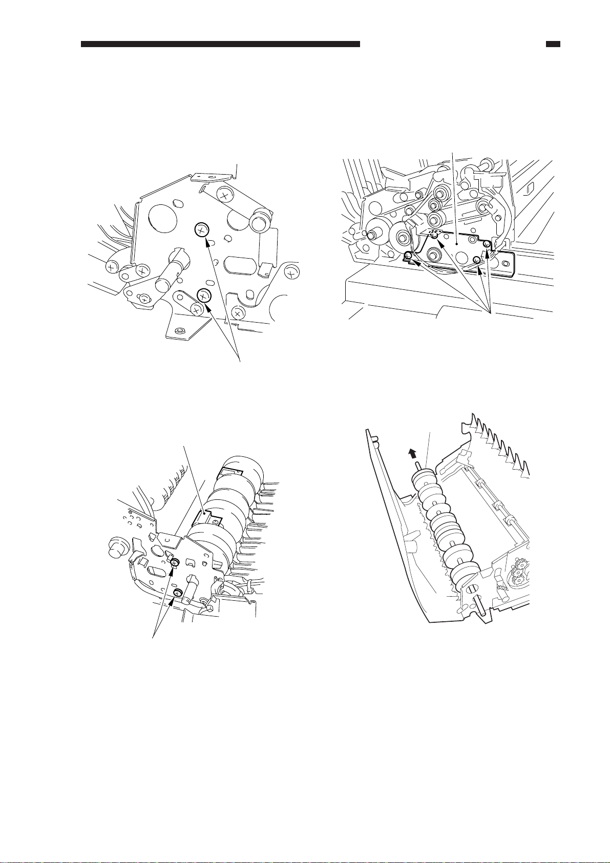
CHAPTER 3 MECHANICAL SYSTEM
11) Remove the two screws [17] at the front
and the two screws [18] at the rear; then,
detach the reversing plate [19] to the
bottom.
[17]
12) Remove the four screws [20], and remove
the front plate [21].
[21]
[20]
Figure 3-332
13) Remove the delivery/reversing roller [22].
Figure 3-330 (front)
[19]
[18]
Figure 3-331 (rear)
[22]
Figure 3-333
COPYRIGHT © 1998 CANON INC. CANON DADF-A1 REV.0 DEC. 1998 PRINTED IN JAPAN (IMPRIME AU JAPON)
3-19
Page 94

CHAPTER 3 MECHANICAL SYSTEM
F. Delivery Roller Unit (bottom
pick-up mode)
1) Remove the body cover.
2) Remove the pick-up motor .
3) Remove the screw [1].
[1] [2] [1]
Figure 3-334
4) Remove the E-ring [2].
5) Remove the screw [3], and remove the
fixing pin [4]; then, detach the delivery
roller unit [5].
[6]
[5]
[5]
Figure 3-336
[2]
Figure 3-335
G . Delivery Roller Unit (top
pick-up mode)
1) Remove the body cover.
2) Remove the screw [1] and the spring [2];
then, disconnect the connector [3].
[8]
[7]
3-20
Figure 3-337
COPYRIGHT © 1998 CANON INC. CANON DADF-A1 REV.0 DEC. 1998 PRINTED IN JAPAN (IMPRIME AU JAPON)
Page 95

CHAPTER 3 MECHANICAL SYSTEM
3) Remove the two screws [4], and detach the
timing belt [5] and the motor unit [6].
[5]
[4]
[6] [4]
Figure 3-338
4) Remove the screw at the front and the two
screws [8] at the rear; then, detach the
delivery roller unit [9].
[8]
[7]
figure 3-339
(back)
[9]
COPYRIGHT © 1998 CANON INC. CANON DADF-A1 REV.0 DEC. 1998 PRINTED IN JAPAN (IMPRIME AU JAPON)
3-21
Page 96

CHAPTER 3 MECHANICAL SYSTEM
H. Reversing Guide
1) Remove the body cover.
2) Remove the gear [1] and the timing belt [2].
[1]
[2]
Figure 3l-340
Reference:
Remove the gear while unlocking it.
3) Disengage the front side [3] and the rear
side [4] of the reversing guide spring.
[3]
Figure 3-342
3-22
[4]
Figure 3-341
COPYRIGHT © 1998 CANON INC. CANON DADF-A1 REV.0 DEC. 1998 PRINTED IN JAPAN (IMPRIME AU JAPON)
Figure 3-343
Page 97

CHAPTER 3 MECHANICAL SYSTEM
4) Remove the screw [5], and detach the
solenoid unit [6].
[6]
[5]
Figure 3-344
5) Remove the reversing sensor jack [7], and
the grounding cord [8].
6) Remove the screw [9], screw [11], and
fixing pin [12]; then, detach the reversing
guide [13].
Caution:
When mounting the fixing pin, be sure
that its position is as it was initially.
[7]
[13] [12] [11] [10] [9]
Figure 3-346
[8]
Figure 3-345
COPYRIGHT © 1998 CANON INC. CANON DADF-A1 REV.0 DEC. 1998 PRINTED IN JAPAN (IMPRIME AU JAPON)
3-23
Page 98

CHAPTER 3 MECHANICAL SYSTEM
I . Stopper Plate Solenoid
1. Removing the Stopper Plate
Solenoid
1) Remove the body cover.
2) Remove the two screws [1], and remove
the original tray mounting plate [2].
[1] [2] [1]
2. Making Adjustments
1) Secure the solenoid [1] in place where the
stopper [3] (rubber block) butts against the
rear edge of the stopper plate [2] when the
plunger of the solenoid [1] is at the end of
its stroke.
[1][2][3]
Figure 3-349
Figure 3-347
3) Remove the two screws, and disconnect
the connector [4]; then, remove the stopper
plate solenoid [5].
[3]
J. Positioning the Paper
Retaining Plate Solenoid
(SL2)
1) Prepare test strips.
Cut a sheet of A4 or LTR paper (64 g/m
into widths of about 70 mm each.
1/3
1/3
1/3
Vertical
Figure 3-350
70 mm (approx.)
2
)
3-24
[5]
[4]
Figure 3-348
COPYRIGHT © 1998 CANON INC. CANON DADF-A1 REV.0 DEC. 1998 PRINTED IN JAPAN (IMPRIME AU JAPON)
Page 99

CHAPTER 3 MECHANICAL SYSTEM
2) Remove the front cover and the cover.
3) Shift bits [5] and [6] of the DIP switch
(DSW1) on the DADF controller to ON,
and press the push switch.
• The pick-up roller starts to rotate and will
stop at the top pick-up mode pick-up
position.
4) When the pick-up roller has stopped, press
the push switch (SW3) on the DADF
controller once again.
• The motor will stop operation.
5) Secure the paper retaining solenoid in
place so that the delivery roller [2] (pick-up
roll for top pick-up mode) is in firm contact
with the pick-up roll [3] when the plunger
[1] of the paper retaining solenoid is fully
pushed.
[2]
6) Push in s test strip prepared in step [1]
between the delivery roller and the pick-up
roller while pushing the plunger of the
paper retaining solenoid fully. Check to
make sure that the delivery roller rotates
when the rear and the front pick-up roller is
tested this way.
Test sheet
[1]
Figure 3-351
[3]
Figure 3-352
Reference:
When pulling the test strip, the one-way
clutch will operate to hold the delivery
roller from rotating.
7) If the delivery roll does not rotate when a
test strip is pushed in, go back to step 3).
8) Shift the bits of the DIP switch (DSW1) on
the DADF controller PCB back to initial
configuration.
COPYRIGHT © 1998 CANON INC. CANON DADF-A1 REV.0 DEC. 1998 PRINTED IN JAPAN (IMPRIME AU JAPON)
3-25
Page 100

CHAPTER 3 MECHANICAL SYSTEM
K. Positioning the Paper
Deflecting Solenoid (SL3)
1) Remove the body cover.
2) Loosen the fixing screw [1], and tighten it
when the stroke of the solenoid [2] is 4.5
mm.
[1]
4.5mm
[2]
3) Remove the E-ring [4] and the bush [5].
[5]
[4]
Figure 3-355
4) Remove the two E-rings [6], gear [7], and
bush [8]; the, detach the delivery roller [9].
(Take care not to drop the pin.)
Figure 3-353
L. Stamp Solenoid
1) Remove the delivery roller unit (top pickup mode).
2) Remove the screw [1] and spring [2]; then,
detach the flapper plate [3].
[2]
[9]
[8]
[6]
[7]
[6]
Figure 3-356
3-26
[3]
[1]
Figure 3-354
COPYRIGHT © 1998 CANON INC. CANON DADF-A1 REV.0 DEC. 1998 PRINTED IN JAPAN (IMPRIME AU JAPON)
 Loading...