

Page 1
DADF-B1
REVISION 0
APR. 1999
COPYRIGHT © 1999 CANON INC. CANON DADF-B1 REV.0 APR. 1999 PRINTED IN JAPAN (IMPRIME AU JAPON)
FY8-13G6-000
Page 2

IMPORTANT
THIS DOCUMENT IS PUBLISHED BY CANON INC., JAPAN, TO SERVE AS A SOURCE OF
REFERENCE FOR WORK IN THE FIELD .
SPECIFICATIONS AND OTHER INFORMATION CONTAINED HEREIN MAY VARY SLIGHTLY
FROM ACTUAL MACHINE VALUES OR THOSE FOUND IN ADVERTISING AND OTHER
PRINTED MATTER.
ANY QUESTIONS REGARDING INFORMA TION CONTAINED HEREIN SHOULD BE DIRECTED
TO THE COPIER SERVICE DEPAR TMENT OF THE SALES COMPANY.
THIS DOCUMENT IS INTENDED FOR ALL SALES AREAS, AND MA Y CONTAIN INFORMATION
NOT APPLICABLE T O CERTAIN AREAS.
COPYRIGHT © 1999 CANON INC.
Printed in Japan
Imprimé au Japon
Use of this manual should be strictly supervised to avoid disclosure of confidential
information.
Prepared by
OFFICE IMAGING PRODUCTS TECHNICAL SUPPORT DIVISION
CANON INC.
5-1, Hakusan 7-chome, Toride, Ibaraki, 302-8501 Japan
COPYRIGHT © 1999 CANON INC. CANON DADF-B1 REV.0 APR. 1999 PRINTED IN JAPAN (IMPRIME AU JAPON)
Page 3

INTRODUCTION
This Service Manual provides information needed to service the ADF in the field. This Service
Manual consists of the following chapters:
Chapter 1 “General Description” introduces the ADF’s features and specifications, and shows
how to operate it.
Chapter 2 “Basic Operation” introduces the ADAF’s mechanical and electrical systems; it also
explains the principles used in these systems and the timing at which they are
operated with reference to the ADAF’s electrical circuitry.
Chapter 3 “Mechanical System” explains the ADAF’s mechanical construction and how its
parts may be disassembled/assembled and adjusted.
Chapter 4 “Maintenance and Servicing” provides tables of periodically replaced parts and
consumables/durables and scheduled servicing charts.
Chapter 5 “Troubleshooting” provides tables of maintenance/inspection, standards/
adjustments, and problem identification (image fault/malfunction).
Appendix contains a general timing chart and general circuit diagrams.
The descriptions in this Service Manual are subject to change without notice for product
improvement or other purposes, and major changes will be communicated in the form of Service
Information bulletins.
All service persons are expected to have a good understanding of the contents of this Service
Manual and all relevant Service Information bulletins, and be able to identify and isolate faults in the
machine.
COPYRIGHT © 1999 CANON INC. CANON DADF-B1 REV.0 APR. 1999 PRINTED IN JAPAN (IMPRIME AU JAPON)
i
Page 4

Page 5

CONTENTS
CHAPTER 1 GENERAL DESCRIPTION
I. FEATURES.................................1-1
II. SPECIFICATIONS ......................1-2
III. NAMES OF PARTS .................... 1-4
A. External View .........................1-4
B. Cross Section.........................1-4
IV. OPERATIONS .............................1-5
CHAPTER 2 BASIC OPERATION
I. BASIC CONSTRUCTION........... 2-1
A. Outline of Electrical Circuitry ....2-1
B. Inputs to the ADF Controller
PCB........................................2-2
C. Outputs from the ADF Controller
PCB........................................2-4
II. BASIC OPERATIONS................. 2-5
A. Outline.................................... 2-5
B. Detecting an Original .............2-6
A. Original Set Indicator .............1-5
B. Making Copies ....................... 1-5
C. Warnings and Actions ............1-5
D. Routine Maintenance by the
User........................................1-6
C. Picking Up and Separating
Originals...............................2-11
D. Moving Originals .................. 2-18
E. Turning Over an Original/
Delivery................................2-23
F. Movement of Originals .........2-32
G. Detecting an Original Jam ... 2-43
H. Alarm Detection ...................2-47
I. Power Supply ....................... 2-50
CHAPTER 3 MECHANICAL SYSTEM
I. BASIC CONSTRUCTION ...............3-1
A. External Covers .....................3-1
B. Removing the Feed Belt Unit...3-4
C. ADF Controller PCB .............. 3-5
II. DRIVE SYSTEM ............................3-6
A. Removing the Pickup Unit .....3-6
B. Removing the Separation
Motor (M1) ..............................3-6
Removing the Feed Motor (M2)
C.
D. Reversal Delivery Unit ...........3-8
E. Removing the Reversal Delivery
Motor (M3) ..............................3-9
III. FEEDING SYSTEM .................. 3-10
A. Removing the Separation Pad
Assembly .............................3-10
B. Removing the Separation
Roller ....................................3-11
C. Removing the Pickup Roller ..3-12
....3-7
Mounting the Separation Roller
D.
Unit ........................................
E. Removing the Reversing Roller
and Feed Roller ................... 3-14
F. Replacing the Feed Belt ......3-16
VI. SENSORS ..................................3-18
A. Removing the Original Set Sen-
sor PCB (U503)....................3-18
B. Removing the Original Set Indi-
cator LED PCB.....................3-18
C. Removing the Last Original
Sensor PCB (U504) .............3-19
D . Original Width Detecting Volume
(VR)......................................3-19
E. Removing the Pre-Registration
Sensor (U502)......................3-21
F. Removing the Reversal Outlet
Sensor (U505)......................3-21
3-13
COPYRIGHT © 1999 CANON INC. CANON DADF-B1 REV.0 APR. 1999 PRINTED IN JAPAN (IMPRIME AU JAPON)
iii
Page 6

CHAPTER 4
MAINTENANCE AND SERVICING
I. PERIODICALLY REPLACED
PARTS ........................................ 4-1
CONSUMABLES AND
II.
DURABLES...................................
4-1
CHAPTER 5 TROUBLESHOOTING
I. STANDARDS AND ADJUST-
MENTS........................................5-1
A. Mechanical System................5-1
B. Electrical System ................... 5-4
II. TROUBLESHOOTING................5-9
A. Troubleshooting
Malfunctions......................... 5-10
III. ARRANGEMENT OF THE ELEC-
TRICAL PARTS ........................ 5-12
A. Motors, Solenoids, and
Sensors................................5-12
B. PCBs....................................5-14
III. SCHEDULED SERVICING
CHART........................................4-2
IV. VARIABLE RESISTORS (VR),
LIGHT-EMITTING DIODES, AND
CHECK PINS BY PCB ............. 5-15
A. ADF Controller PCB ............ 5-15
B. Sensor PCBs ....................... 5-16
C. Indicator PCB.......................5-18
V. SERVICE MODE AND DIP
SWITCH.................................... 5-19
A. Outline..................................5-19
B. Service Mode .......................5-20
C. Using the DIP Switch ...........5-28
VI. SELF DIAGNOSIS .................... 5-32
A. ADF Self Diagnosis ............. 5-32
APPENDIX
A. GENERAL TIMING CHART ......... A-1
B. SIGNALS AND
ABBREVIATIONS ...................... A-5
C. GENERAL CIRCUIT
DIAGRAM .................................. A-7
D. ADF CONTROLLER PCB ......... A-8
E. PRE-REGISTRATION SENSOR
PCB .......................................... A-12
F. REVERSAL OUTLET SENSOR
PCB .......................................... A-13
G. ORIGINAL SET INDICATOR LED
PC B..........................................A-15
H. ORIGINAL SET SENSOR .......A-17
I. LAST ORIGINAL SENSOR ..... A-18
J. SPECIAL TOOLS ..................... A-19
K. SOLVENTS AND OILS ............ A-20
iv
COPYRIGHT © 1999 CANON INC. CANON DADF-B1 REV.0 APR. 1999 PRINTED IN JAPAN (IMPRIME AU JAPON)
Page 7

CHAPTER 1
GENERAL DESCRIPTION
I. FEATURES................................. 1-1
II. SPECIFICATIONS ...................... 1-2
III. NAMES OF PARTS .................... 1-4
A. External View .........................1-4
B. Cross Section.........................1-4
IV. OPERATIONS .............................1-5
COPYRIGHT © 1999 CANON INC. CANON DADF-B1 REV.0 APR. 1999 PRINTED IN JAPAN (IMPRIME AU JAPON)
A. Original Set Indicator .............1-5
B. Making Copies ....................... 1-5
C. Warnings and Actions ............1-5
D. Routine Maintenance by the
User........................................1-6
Page 8

Page 9

CHAPTER 1 GENERAL DESCRIPITON
I. FEATURES
1. Small in size, and light in weight.
It is a document feeder designed as a single-frame unit for small size and light weight.
2. Handles double-sided originals.
It is equipped with a reversing delivery unit, capable of turning over originals and returning them
to the copyboard glass.
3. Wingless design.
Its delivery tray is of an integrated construction.
4. Automatic identification of original size.
It is capable of identifying the size of an original in terms of lengthwise (feeding) and
breadthwise directions for communication to its host copier.
4. Handles mixed sizes.
It can accommodate originals of different sizes (of the same width, i.e., configuration).
5. Accommodates thick originals.
It is equipped with a book equalizing hinge, enabling the use of a thick original (50 mm thick;
e.g., book).
6. Reversal delivery flapper.
It rotates the reversal delivery motor clockwise and counterclockwise to open and close the
flapper, switching the feeding path.
COPYRIGHT © 1999 CANON INC. CANON DADF-B1 REV.0 APR. 1999 PRINTED IN JAPAN (IMPRIME AU JAPON)
1-1
Page 10

CHAPTER 1 GENERAL DESCRIPITON
II. SPECIFICATIONS
Item Specifications
Pickup method Automatic pickup/delivery
Type of original Original tray: double-sided sheet (52 to 105 g/m
Copyboard glass: book (50 mm thick max.)
Size of original A3 (279 mm x 431.8 mm; 11"x17") to A5 (STMT)
Length: 140 to 432 mm (feeding direction)
Width: 140 to 297 (305) mm
Note: The values in parentheses indicate when the guide lock is released.
Orientation of original Face up
1st page at top
Placement of original Center reference
Original separation Separation pad (top separation)
2
); see Note 1.
Original processing
mode
Height of stack
(80 g/m
Mixing sizes Possible (of the same width)
Size identification Yes (feeding direction + default width)
Residual original
detection
2-on-1 function No (by copier's memory)
Stamp No
Last original detection 690 msec or less
Communication with
copier
Power supply 24 VDC (from copier)
Serial numbers ZSB xxxxx AB
Maximum power
supply
2
paper)
Single-sided original processing (small-size, large-size), double-sided original
processing
30 sheets (small size; A4, B5, A5, STMT, LTR)
15 sheets (large-size; A3, 279x431.8 mm/11"x17", B4, LGL)
Yes (by LED)
IPC 2
ZSC xxxxx INCH/A
ZSD xxxxx A
ZSE xxxxx AB/INCH
160 W or less at peak; 39 W in average
Weight 12.8 kg (approx.)
Dimensions 583 (W) x 506 (D) x 179 (H) mm
Operating environment
temperature/humidity
range
Same as copier
Table 1-201
1-2
COPYRIGHT © 1999 CANON INC. CANON DADF-B1 REV.0 APR. 1999 PRINTED IN JAPAN (IMPRIME AU JAPON)
Page 11
CHAPTER 1 GENERAL DESCRIPITON
Time to replace originals
Point of exposure
(leading edge of image)
Note 1:
The following may not be used as an
original:
• Sheet with holes (as for filing).
• Sheet with a staple, clip, or adhesive.
• Sheet with a cut-and-paste patch.
• Sheet with a carbon back.
• Sheet with large curling, bending, or
wrinkling.
If an original has large curling, straighten
it out as much as possible, and place it so that
the curling edge is the trailing edge.
Note:
The specifications are subject to change
for product improvement.
Note 2:
Time Taken to Replace Originals
The value indicates the time passing from
when an original is moved to when its trailing
edge reaches the point of exposure. However,
it does not include separation of the original.
Figure 1-201
COPYRIGHT © 1999 CANON INC. CANON DADF-B1 REV.0 APR. 1999 PRINTED IN JAPAN (IMPRIME AU JAPON)
1-3
Page 12
CHAPTER 1 GENERAL DESCRIPITON
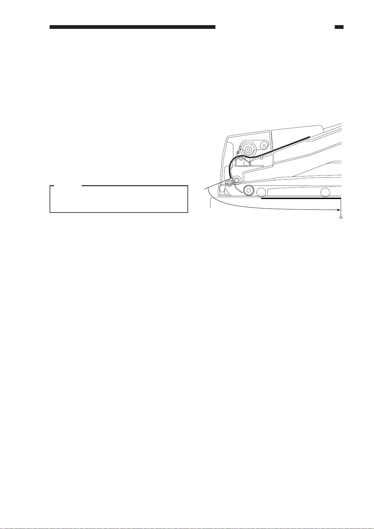
III. NAMES OF PARTS
A. External view
[2]
[1][3]
[6]
[4]
[8]
B. Cross Section
[5]
[7]
Figure 1-301
[1] Original tray
[2] Auxiliary tray
[3] Slide guides
[4] Original Set indicator
[5] Last original sensor
[6] Pickup unit cover
[7] Reversal delivery unit cover
[8] Original delivery tray
[4]
[5]
Pickup Assembly
[1] Pickup roller
[2] Lifter
[3] Separation pad
[4] Separation roller
[5] Registration roller
[3]
[2]
[7] [8] [9]
Pickup assembly
[1]
[12]
[6]
Feeding assembly
Figure 1-302
Feeding Assembly
[6] Feeding belt
[7] Feeding belt drive roller
[8] Retaining roll
[9] Feeding belt linkage roller
Reversal Delivery Assembly
[10] Reversal delivery flapper
[11] Reversal delivery
registration roller
[12] Reversing roller
Reversal
delivery
assembly
[11]
[10]
1-4
COPYRIGHT © 1999 CANON INC. CANON DADF-B1 REV.0 APR. 1999 PRINTED IN JAPAN (IMPRIME AU JAPON)
Page 13
CHAPTER 1 GENERAL DESCRIPITON
IV. OPERATIONS
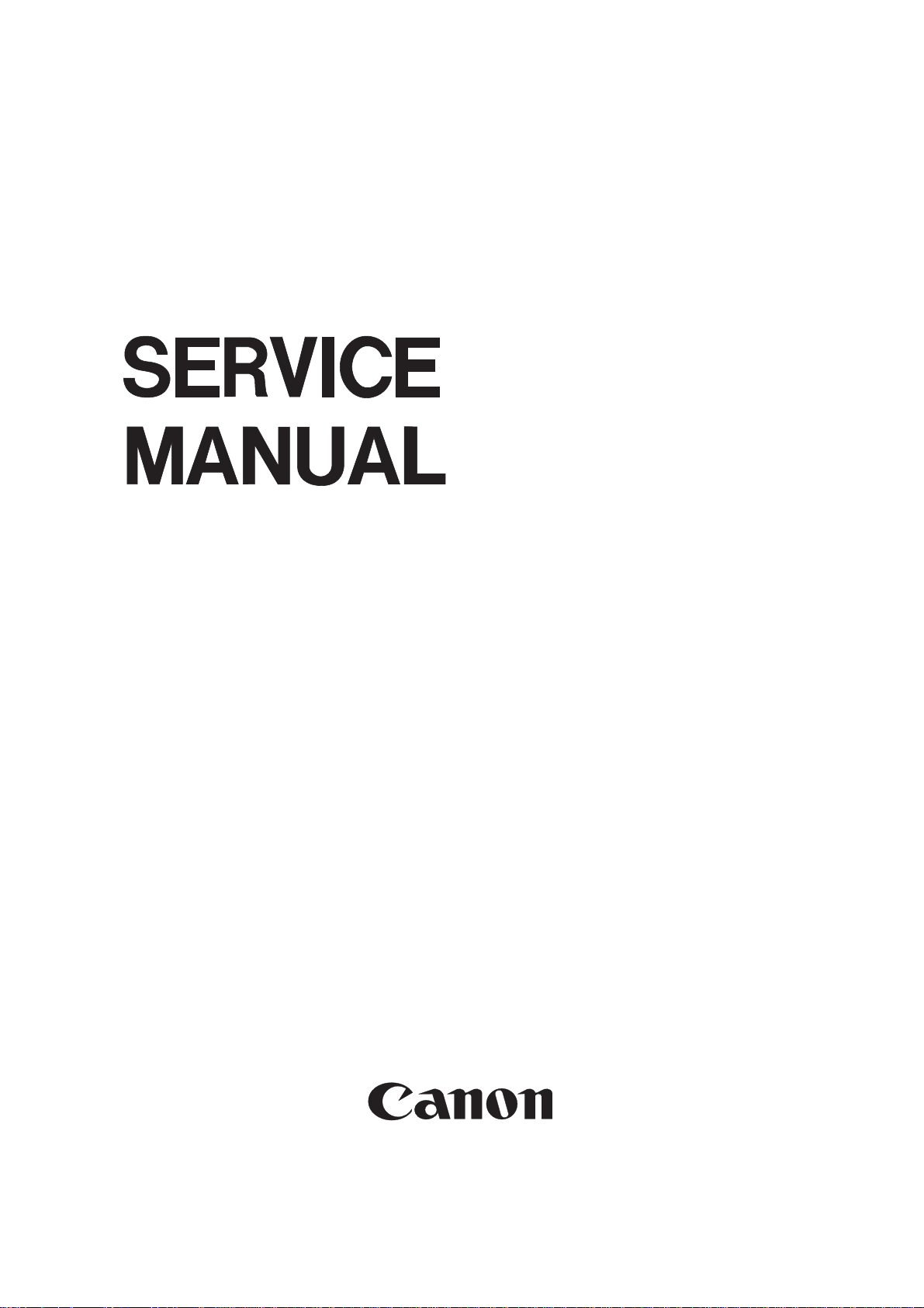
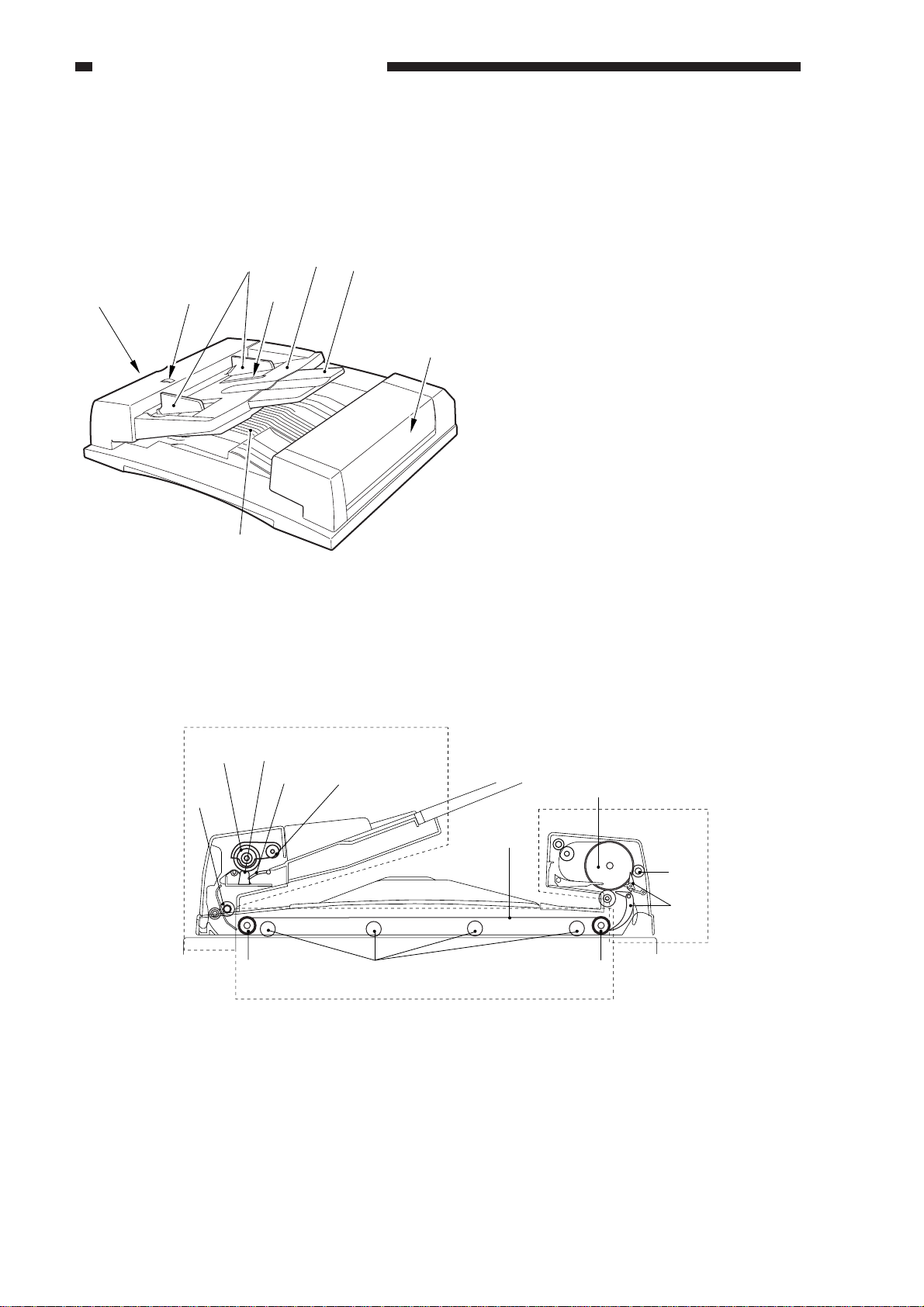
A. Original Set Indicator
The Original Set indicator turns on when an original is on the original tray, and it starts to flash
when a jam occurs.
Figure 1-401
B. Making Copies
1) Adjust the slide guides to suit the size of the originals.
2) Place the stack of originals against the end plate of the original tray with the first page on top.
3) Set the copier to the appropriate copying mode.
4) Press the copier’s Copy Start key.
C. Warnings and Actions
You can suspect an original jam if the Original Set indicator has started to flash. Make the
following checks, and take the appropriate actions:
1) Open the pickup unit cover and the reversal delivery unit; then, remove any original jam.
2) Remove the originals from the original tray.
3) Open the ADF, and remove any original jam.
4) Remove any original from the copyboard glass.
5) Close the ADF.
6) Put the originals back into order, and place the stack on the original tray once again.
7) Press the copier’s Copy Start key.
COPYRIGHT © 1999 CANON INC. CANON DADF-B1 REV.0 APR. 1999 PRINTED IN JAPAN (IMPRIME AU JAPON)
1-5
Page 14

CHAPTER 1 GENERAL DESCRIPITON
D. Routine Inspection by the
User
Instruct the user to clean the following on a regular basis:
1. Copyboard Glass
Clean it using a cloth moistened with water or alcohol; then, dry wipe it.
2. Feeding Belt
Clean it using water or alcohol.
3. Others
If any part of the external panels of the ADF is soiled, clean it with a solution of mild detergent;
then, dry wip it.
1-6
COPYRIGHT © 1999 CANON INC. CANON DADF-B1 REV.0 APR. 1999 PRINTED IN JAPAN (IMPRIME AU JAPON)
Page 15

CHAPTER 2
BASIC OPERATION
I. BASIC CONSTRUCTION........... 2-1
A. Outline of Electrical Circuitry ....2-1
B. Inputs to the ADF Controller
PCB........................................2-2
C. Outputs from the ADF Controller
PCB........................................2-4
II. BASIC OPERATIONS................. 2-5
A. Outline.................................... 2-5
B. Detecting an Original .............2-6
COPYRIGHT © 1999 CANON INC. CANON DADF-B1 REV.0 APR. 1999 PRINTED IN JAPAN (IMPRIME AU JAPON)
C. Picking Up and Separating
Originals...............................2-11
D. Moving Originals .................. 2-18
E. Turning Over an Original/
Delivery................................2-23
F. Movement of Originals .........2-32
G. Detecting an Original Jam ... 2-43
H. Alarm Detection ...................2-47
I. Power Supply ....................... 2-50
Page 16

Page 17
CHAPTER 2 BASIC OPERATION
I. BASIC CONSTRUCTION
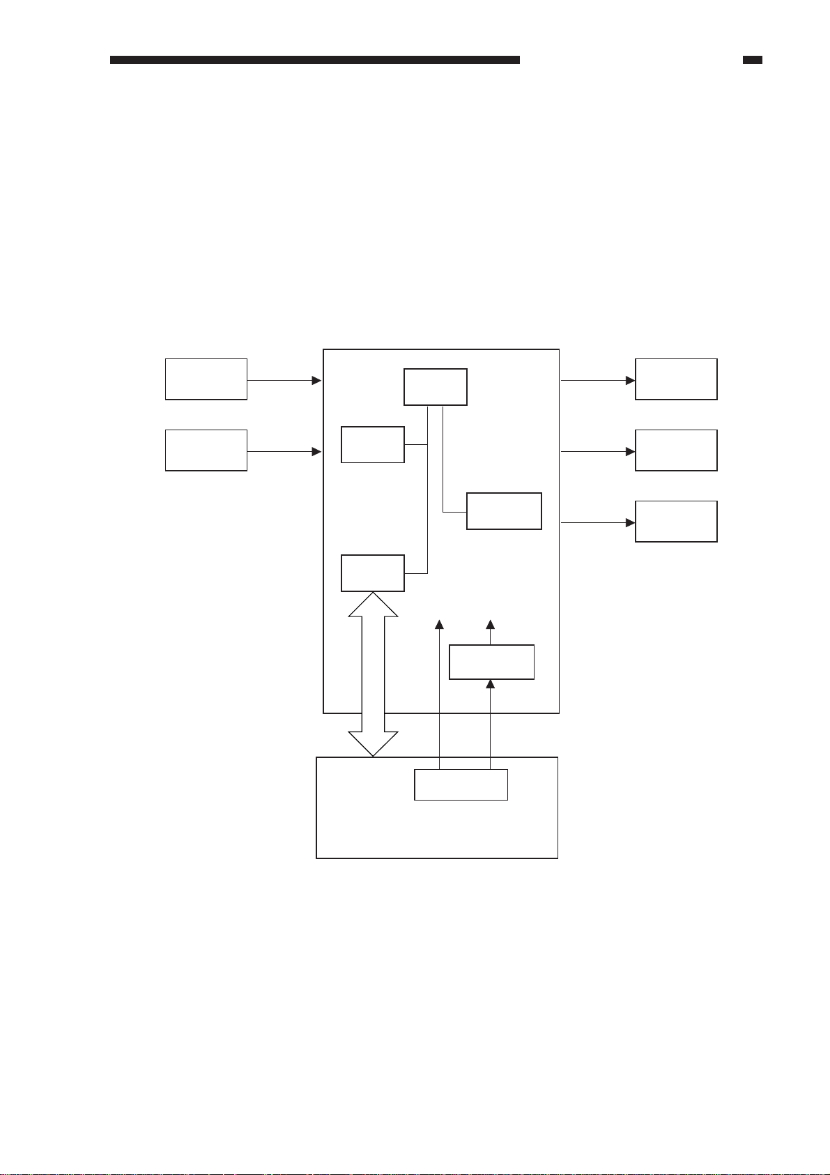
A.
Outline of Electrical Circuitry
The major electrical mechanisms of the ADF are controlled by a microprocessor (CPU) on the
ADF controller PCB.
The microprocessor is designed to read signals from sensors and its host copier to generate
signals used to drive loads (motors, brakes).
ADF controller PCB
Sensor
Variable
resistor
ROM
(Q2)
IPC
(Q3)
CPU
(Q1)
EEPROM
(Q4)
24V 5V
5 VDC
power supply
Power supply
circuit
Motor
Brake
Indicator
LED PCB
Copier
Figure 2-101
COPYRIGHT © 1999 CANON INC. CANON DADF-B1 REV.0 APR. 1999 PRINTED IN JAPAN (IMPRIME AU JAPON)
2-1
Page 18
CHAPTER 2 BASIC OPERATION
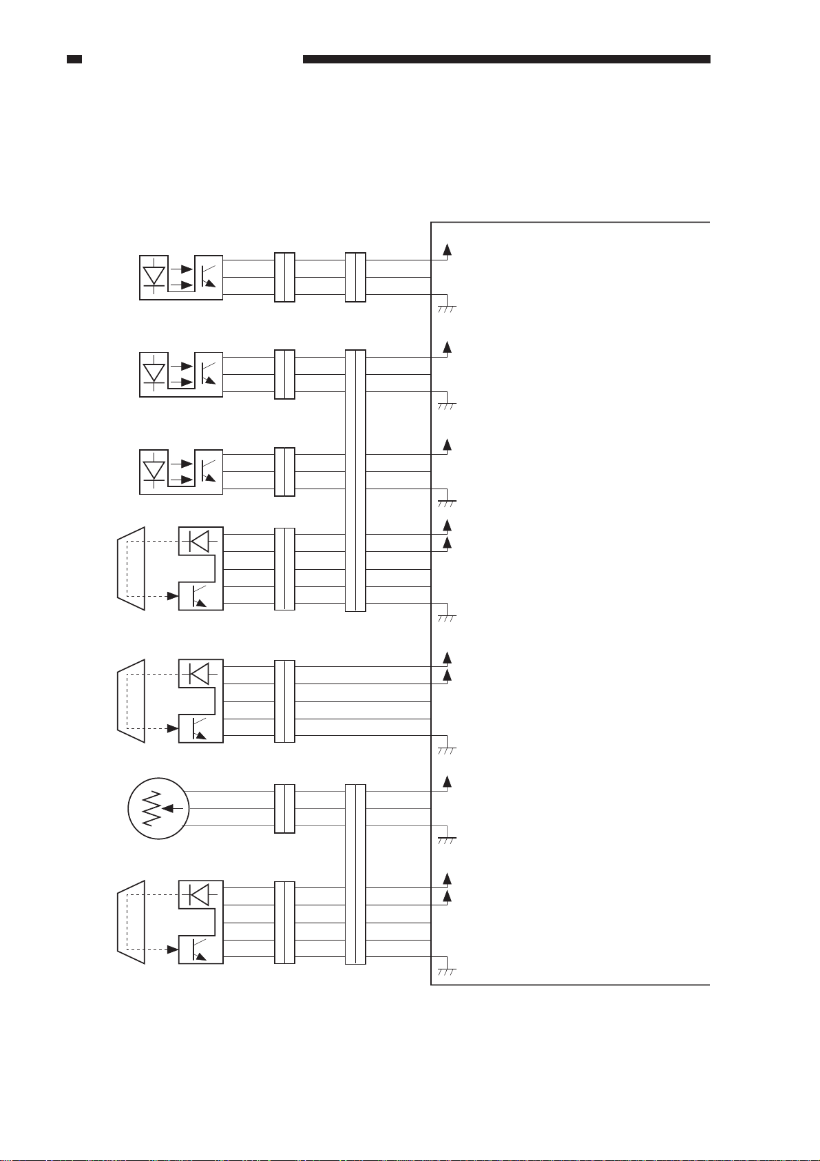
B. Inputs to the ADF Controller PCB
1. Inputs to the ADF Controller PCB (1/2)
ADF controller PCB
Feed motor clock sensor
SR1
Pickup unit cover sensor
SR2
Separation sensor
SR3
Original set sensor
U503
+
3
3
2
2
1
1
3
3
1
1
2
2
J102
3
3
1
1
2
2
J103
4
4
3
3
2
2
1
5
J301
10
1
11
5
1
2
3
J1101J101
1
3
2
4
6
5
8
9
7
J1102
3
2
1
11
9
10
8
6
7
4
3
2
1
5
J6A-3
J6FA-2
J6FA-1
J6A-4
J6FA-6
J6FA-5
J6A-7
J6FA-9
J6FA-8
J6A-11
J6FA-12
J6FA-13
J6FA-14
J6FA-10
5V
FMCK
+
5V
SCVR
+
5V
SPR
+
5V
+
24V
EMP
EPLED
While the feed motor is rotating,
alternates between ’1’ and ’0’.
When the pickup unit cover is
opened, ’0’.
(When the light-blocking plate is
not at the sensor.)
When an original is detected, ’0’.
(When the light-blocking plate is
not at the sensor.)
When an original blocks the
sensor, ’0’.
Pre-registration sensor
U502
Original width detecting
volume
U508
Last original sensor
U504
4
2
3
3
5
5
4
4
1
1
J201
1
3
1
2
2
2
3
1
3
J801
4
4
3
2
1
5
J401 J1801
5
3
6
2
7
1
8
5
4
J6B-6
J6FB-5
J6FB-3
J6FB-4
J6FB-7
J6B-8
8
J6FA-9
7
J6FA-10
6
4
J6B-12
3
J6FB-13
2
J6FB-14
J6FB-15
1
J6FB-11
5
Figure 2-102
+
5V
+
24V
ENT
ETLED
+
5V
WIDE
+
5V
+
24V
LAST
LTLED
When the original blocks the
sensor, ’0’.
Generates an analog voltage to
suit the width of the original placed
on the original tray.
When an original blocks the
sensor, ’1’.
2-2
COPYRIGHT © 1999 CANON INC. CANON DADF-B1 REV.0 APR. 1999 PRINTED IN JAPAN (IMPRIME AU JAPON)
Page 19
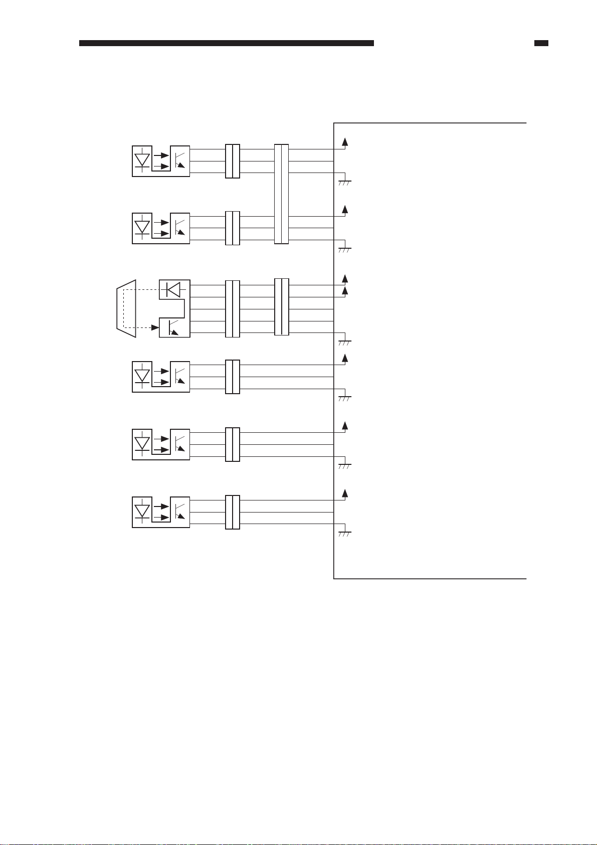
2. Inputs to the ADF Controller PCB (2/2)
Reversal delivery inlet
sensor
SR4
Reversal delivery
registration sensor/delivery sensor
SR5
Reversal outlet sensor
U505
ADF open/closed sensor
SR6
Reversal delivery motor
clock sensor
SR7
Reversal delivery
unit cover sensor
SR8
3
3
1
2
J107
3
1
2
J108
J103
2
3
5
4
1
J501 J502
3
1
2
J109
1
2
3
J110
3
1
2
J111
1
1
3
2
2
4
3
6
1
5
2
2
4
3
3
5
1
4
2
5
1
3
1
2
1
2
3
3
1
2
J1107
6
4
5
3
1
2
2
3
5
4
J6FA-11
1
J7A-1
J6FA-3
J6FA-2
J7A-4
J6FA-6
J6FA-5
J7B-10
J6FA-9
J6FA-7
J6FA-8
J7B-1
J6FA-3
J6FA-2
J7B-6
J6FA-5
J6FA-4
J7B-7
J6FA-9
J6FA-8
+
5V
EENT
+
5V
EREG
+
5V
+
24V
TURN
TULED
+
5V
OPEN*
+
5V
EMCK
+
5V
CHAPTER 2 BASIC OPERATION
ADF controller PCB
When an original is detected, ’1’.
(When the light-blocking plate is at
the sensor.)
When an original is detected, ’1’.
(When the light-blocking plate is at
the sensor.)
When an original blocks the sensor, ’0’.
When the ADF is opened, ’0’.
(When the light-blocking plate is
not at the sensor.)
While the reversing delivery motor is
rotating, alternates between ’1’ and ’0’.
When the reversal delivery unit cover
is opened, ’0’.
(When the light-blocking plate is at
the sensor.)
The asterisk (*) indicates that the signal turns on
when ’0’ (low active).
Figure 2-103
COPYRIGHT © 1999 CANON INC. CANON DADF-B1 REV.0 APR. 1999 PRINTED IN JAPAN (IMPRIME AU JAPON)
2-3
Page 20
CHAPTER 2 BASIC OPERATION
C. Outputs from the ADF Controller PCB
1. Outputs from the ADF Controller PCB (1/1)
Separation motor
J5-1
1
M1
Feed motor
M2
M
M
1
2
1
2
J104
J104
2
1
2
J6FA-2
J6FA-4
J5-3
SPM1
SPM2
FDM1
FDM2
ADF controller PCB
See "Controlling the
Separation Motor (M1)" on p. 2-16.
See "Controlling the
Feed Motor (M2)" on p. 2-21.
Feed motor brake
BK1
BK
Reversal delivery motor
M3
M
Original Set indicator (LED)
U507
1
2
1
2
2
1
J112
J112
J701
1
J6FAJ5-6
2
1
J6FA-2
2
J6B-1
2
J6FA-2
1
J5-5
J9-1
BK
EJM1
EJM2
OGLED
+
24V
When ’0’, the brake (BK1) turns on.
See "Controlling the Reversal
Delivery Motor (M3)" on p. 2-29.
+5
V
When ’0’, the Original Set indicator
turns on.
2-4
Figure 2-104
COPYRIGHT © 1999 CANON INC. CANON DADF-B1 REV.0 APR. 1999 PRINTED IN JAPAN (IMPRIME AU JAPON)
Page 21
CHAPTER 2 BASIC OPERATION
II. BASIC OPERATIONS
A. Outline
The ADF is equipped with three motors for separation, feeding, and delivery (reversal)
and one brake.
The separation motor (M1) is used to separate and pick up originals. The feed motor (M2) is used
to move originals to and stop them at the copyboard glass, while the reversal delivery motor (M3) is
deigned to deliver or reverse originals. The brake (BK) serves to stop the operation of the feed motor
(M2).
ADF controller PCB
Feed motor clock signal (FMCK)
Feed motor drive signal (FDM1, FDM2)
Pickup detection signal (SPR)
Pickup unit cover open/closed detection signal (SCVR)
Feed motor brake drive signal (Bk*)
M1
SR3
SR2
Original pickup tray paper detection signal (EMP)
Original Set indicator ON signal (OGLED)
Separation motor drive signal (SPM1, SPM2)
U507
U508
U503
BK
M2
Last original detection signal (LAST)
Original size detection signal (WIDE)
Pickup registration signal (ENT)
ADF open/closed detection signal (OPEN)
U504
Copier
SR1
Figure 2-201
Reversal/delivery outlet paper detection signal (TURN)
Reversal delivery unit cover open/
closed detection signal (ECVR)
Reversal/delivery motor clock signal (EMCK)
Reversal delivery motor drive signal (EJM1, EJM2)
M3
SR7
SR8
U505
SR6
Reversal/delivery registration signal/
delivery detection signal (EREG)
Reversal/delivery inlet paper detection signal (EENT)
SR5
SR4
COPYRIGHT © 1999 CANON INC. CANON DADF-B1 REV.0 APR. 1999 PRINTED IN JAPAN (IMPRIME AU JAPON)
2-5
Page 22
CHAPTER 2 BASIC OPERATION
B. Detecting an Original
1. Outline
The ADF is equipped with the following
three types of original detecting mechanisms:
a. Detecting the Presence/Absence of
an Original
It detects the presence/absence of an
original on the original tray.
b. Identifying the Size of an Original
It identifies the length (feeding direction)
and width of an original.
c. Detecting the Last Original
It detects the trailing edge of the last
original.
a. Detecting the Presence/Absence of
an Original
The presence/absence of an original on the
original tray is detected by the original set
sensor. When an original is placed on the
original tray, the light from the light-emitting
side of the original set sensor is blocked, and
the light-receiving side of the original set
sensor starts to send the original detection
signal (EMP) to the ADF controller PCB.
In response, the ADF controller PCB
generates the original set indicator ON signal
(OGLED) to turn not the Original Set indicator
(U507).
ADF controller PCB
U507
Original set indicator
ON signal (OGLED)
Original Set sensor Original
Original Set indictor
LED
U503
Figure 2-202
Prism
Original tray paper
detection signal (EMP)
2-6
COPYRIGHT © 1999 CANON INC. CANON DADF-B1 REV.0 APR. 1999 PRINTED IN JAPAN (IMPRIME AU JAPON)
Page 23
CHAPTER 2 BASIC OPERATION
b. Identifying the Size of an Original
The ADF identifies the size of an original
in terms of length (feeding direction) and
width.
The length is computed in reference to the
number of clock signals from the preregistration sensor (U502) and the registration
roller.
When the pre-registration sensor detects
the leading edge of an original (ON) and the
trailing edge (OFF), the ADF controller
computes the time taken by the original to
move past the pre-registration sensor with
reference to the number of clock signals from
the feed motor clock sensor (SR1) to find out
the size in the lengthwise direction (feeding
direction).
The ADF controller uses the result to
identify a default size, and communicates it to
the copier so that copy paper of the appropriate
size may be selected.
The ADF refers to the original width
detecting volume (U508) located inside the
original tray to find out the width of an original.
The original width detecting volume
operates in conjunction with the slide guides,
and the resistance of the voltage varies in
analog mode. The ADF controller uses
changes occurring in the resistance as the
original size detection signal (WIDE), and uses
them to find out the width of a specific original.
Original width detecting volume
ADF controller PCB
Prism
Registration roller
Pre-registration
sensor
U502
BK
Original
Feed motor
M2
SR4
(FMCK)
Feed motor clock signal
Original tray paper detection signal
(ENT)
Figure 2-204
Feed motor clock
sensor
Figure 2-203
COPYRIGHT © 1999 CANON INC. CANON DADF-B1 REV.0 APR. 1999 PRINTED IN JAPAN (IMPRIME AU JAPON)
2-7
Page 24
CHAPTER 2 BASIC OPERATION
Default size Length (mm) Width (mm)
B5R
A5
A4R
B5
B4
COMPUTER
A4
A3
237 to 297
128 to 188
277 to 317
162 to 222
344 to 404
361 to 421
190 to 250
400 to 460
180 to 184
208 to 212
255 to 259
277.4 to 281.4
295 to 299
Default size Length (mm) Width (mm)
STMT
LTRR
FLSC
LGL
LTR
COMPUTER
11x17
(297.4 to 431.8)
120 to 180
259 to 309
310 to 343
343 to 396
196 to 256
361 to 411
412 to 472
213.9 to 217.9
277.4 to 281.4
· Slide Guide Lock
The ADF is equipped with a slide guide
lock so that the slide guides will not move any
farther than 297 mm (A4 length or A3 width).
If an original larger than 297 mm is used,
the slide guide lock may be released (to
accommodate up to 305 mm). The length of the
original, nevertheless, must be 32 mm or less.
The copier assumes that any original is an
original of a default size based on the data on
length and width from the ADF. Tables 2-201,
-202, and -203 show the default sizes that the
copier will assume in reference to the length
and width data.
· A/B-Configured ADF
Figure 2-205
A default size is identified in reference to
±10 mm for the length of an original, and ±5
mm for the width. Any lengths or widths
falling outside these ranges will be assumed to
represent a non-default size original.
Table 2-201
· Inch-Configured ADF
2-8
COPYRIGHT © 1999 CANON INC. CANON DADF-B1 REV.0 APR. 1999 PRINTED IN JAPAN (IMPRIME AU JAPON)
A default size is identified in reference to
±10 mm for the length of an original, and±5
mm for the width. Any lengths or widths falling
outside these ranges will be assumed to
represent a non-default size original.
Table 2-202
Page 25
CHAPTER 2 BASIC OPERATION
U504
U502
Last original sensor
ADF controller PCB
Prism
Original
Pre-registration
sensor
Last original detection signal
(LAST)
Last original sensor
Original
Original tray
· Inch/A/B-Configured ADF
Default size Length (mm) Width (mm)
B5R
A5
A4R
STMT
LTRR
FLSC
LGL
B5
B4
LTR
COMPUTER
11x17
(297.4 to 431.8)
A4
237 to 297
128 to 188
277 to 337
120 to 180
259 to 309
310 to 343
343 to 396
162 to 222
344 to 404
196 to 256
361 to 411
412 to 472
190 to 250
180 to 184
208 to 212
213.9 to 217.9
255 to 259
277.4 to 281.4
295 to 299
assume the original as the last original and
sends the last original detection signal (LAST)
to the copier so as to prevent pickup of copy
paper.
Last Original Detection and Original Sizes
default size: B5, A4, LTR
length: 170 to 190 mm; 205 to
226 mm
A3
400 to 460
A default size is identified in reference to
±10 mm for the length of an original, and ±5
mm for the width. Any lengths or widths
falling outside these ranges will be assumed to
represent a non-default size original.
Table 2-203
c. Identifying the last Original
A copier with a long paper path (from
cassette to drum) is designed to pick up copy
paper early to enable faster copying operation.
As such, when the ADF picks up the last
original and places it on the copyboard glass,
the copier may already have finished picking
up copy paper.
The ADF moves the second original as far
as the pre-registration sensor immediately after
it picks up the first original (advance
separation). If the last original sensor does not
detect an original, the ADF controller will
Figure 2-206
Figure 2-207
COPYRIGHT © 1999 CANON INC. CANON DADF-B1 REV.0 APR. 1999 PRINTED IN JAPAN (IMPRIME AU JAPON)
2-9
Page 26

CHAPTER 2 BASIC OPERATION
· Counting Originals
The number of times that the registration
sensor has turned on in response to the trailing
edge of an original is used as the number of
originals.
The ADF is not equipped with an original
feed mode for counting originals when making
double-sided copies of single-sided originals.
The originals are copied in order of how they
are picked up and delivered accordingly.
2-10
COPYRIGHT © 1999 CANON INC. CANON DADF-B1 REV.0 APR. 1999 PRINTED IN JAPAN (IMPRIME AU JAPON)
Page 27
CHAPTER 2 BASIC OPERATION
C. Picking Up and Separating Originals
1. Outline
The pickup roller and the lifter are moved up so as to hold the entire stack of originals, and the
separation roller is rotated. When this takes place while the stack is butted against the separation pad,
the topmost sheet is separated from the rest of the stack.
The pickup roller is moved down and the lifter is moved up by rotating the separation motor (M1)
counterclockwise. On the other hand, the pickup roller is moved up, the lifter is moved down, and the
separation roller is turned by rotating the separation motor (M1) clockwise.
The separation assembly is equipped with a separation sensor (SR3) to monitor the movement of
originals.
When the copier’s Copy Start key is pressed while originals are placed on the original tray, the
originals are picked up and separated in the following sequence of operations:
Separation
sensor
Registration roller
Separation
roller
Pickup roller
Lifter
Separation pad
Pre-registration sensor
Figure 2-208
COPYRIGHT © 1999 CANON INC. CANON DADF-B1 REV.0 APR. 1999 PRINTED IN JAPAN (IMPRIME AU JAPON)
2-11
Page 28
CHAPTER 2 BASIC OPERATION
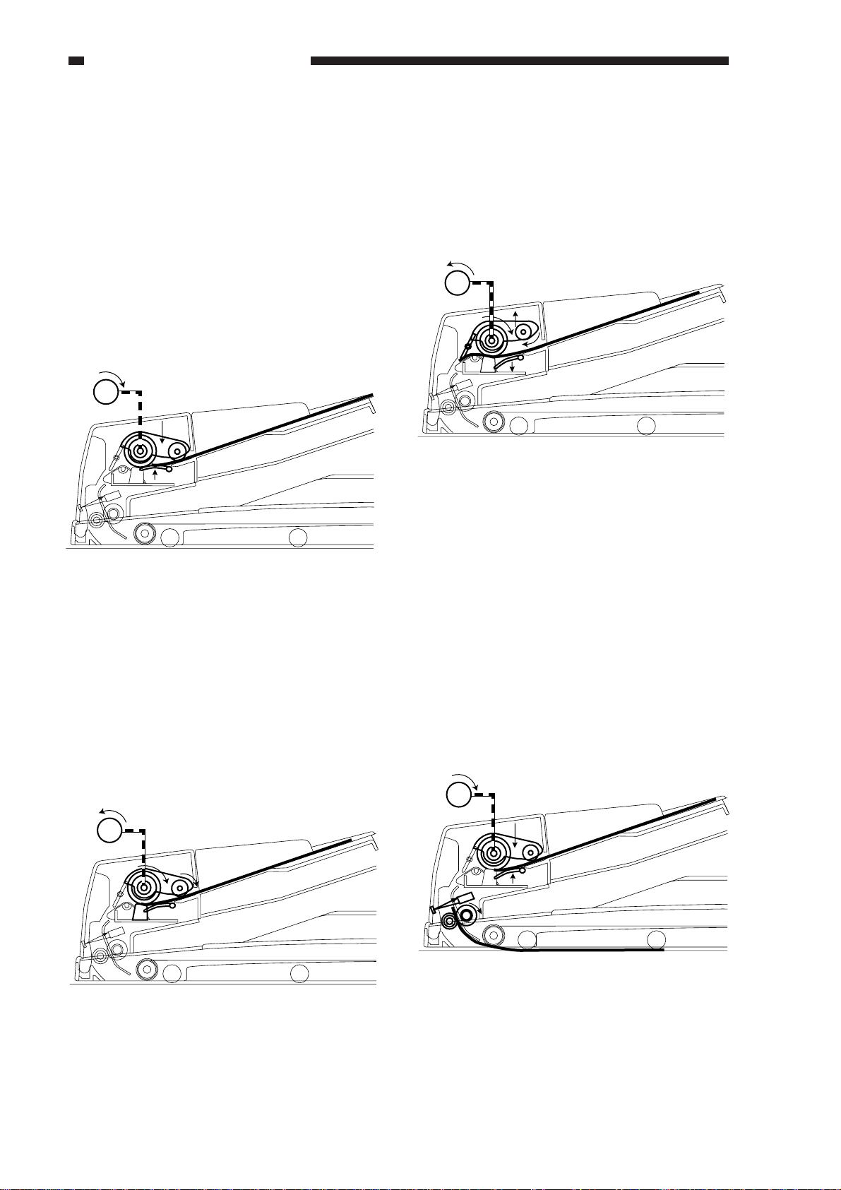
1. Starting Ascent (pre-separation)
When the separation motor (M1) rotates
counterclockwise, the lifter moves up to hold
up the entire stack of originals from under,
while at the same time the pickup roller moves
down onto the stack to hold it in place.
The separation motor rotates
counterclockwise for 250 msec and then stops.
Figure 2-209
3. Arching
The original is butted against the
registration roller, and is made to arch. The
separation roller stops to rotate 52 msec after
the pre-registration sensor (U502) detects the
leading edge of the original.
Figure 2-211
2. Pickup/Separation Operations
When the separation motor (M1) rotates
clockwise, its drive reaches the pickup roller
and the separation roller and, as a result, the
first (topmost) original is picked up. The
separation pad is used to make sure that only
one original is separated and moved to the
registration roller.
At the end of this operation, the lifter starts
to move down, and then the pickup roller
moves up.
2-12
Figure 2-210
COPYRIGHT © 1999 CANON INC. CANON DADF-B1 REV.0 APR. 1999 PRINTED IN JAPAN (IMPRIME AU JAPON)
Page 29
CHAPTER 2 BASIC OPERATION
2. Moving Up the Pickup Roller Unit
The pickup roller and the lifter are designed to operate (move up and down) in conjunction with
the separation motor (M1).
■ Separation Motor Rotating Counterclockwise
When the separation motor rotates counterclockwise, the work of a cam disengages the lock used
to keep the pickup roller in place, and the pickup roller starts to move down on its own weight.
In addition, the drive reaches the arm of the lifter, causing the lifter to move up. This operation
moves up the originals while they are held intact in preparation for pickup operation.
Separation motor
Pickup roller
Lifter
Counter clockwise
Separation roller
Figure 2-212
When the separation motor (M1) rotates clockwise, the work of the cam moves down the lifter,
and then the pickup roller returns to the ascent position. When the separation motor is rotating
clockwise, the work of the one-way clutch lets the rotation drive of the separation motor (M1) to
reach the separation roller and the pickup roller. When the separation motor rotates
counterclockwise, its rotation drive will not reach the separation roller or the pickup roller.
■ Separation Motor Rotating Clockwise
Separation motor
Clockwise
Pickup roller
Separation roller
Lifter
Figure 2-213
COPYRIGHT © 1999 CANON INC. CANON DADF-B1 REV.0 APR. 1999 PRINTED IN JAPAN (IMPRIME AU JAPON)
2-13
Page 30
CHAPTER 2 BASIC OPERATION
1. When the copier’s Copy Start key is
pressed, the separation motor (M1) starts to
rotate counterclockwise. In response, the
lock used to keep the pickup roller in place
becomes disengaged, and the pickup roller
falls down on the original on its own
weight.
The work of a cam, on the other hand,
moves up the lifter and, consequently, the
original.
The separation motor rotates
counterclockwise
for 250 msec and then stops to end ascent.
M1
3. A moment after the separation motor starts
to rotate clockwise, the lifter starts to move
down by the work of the cam.
Then, the pickup roller starts to move up
while rotating, returning to its initial
position.
M1
Figure 2-216
Figure 2-214
2. When the pickup roller stops moving
down and the lifter stops moving up, the
separation motor starts to rotate clockwise
so that its rotation drives the separation
roller and the pickup roller, moving the
first original to the separation assembly.
M1
4. When the pre-registration sensor (U502)
detects the trailing edge of the original
(OFF), the separation motor starts to rotate
counterclockwise once again. In response,
the lock used to keep the pickup roller in
place becomes disengaged, and the pickup
roller falls down onto the original on its
own weight.
The work of the cam, on the other hand,
moves up the lifter to hold up the original.
M1
2-14
Figure 2-217
Figure 2-215
COPYRIGHT © 1999 CANON INC. CANON DADF-B1 REV.0 APR. 1999 PRINTED IN JAPAN (IMPRIME AU JAPON)
Page 31

CHAPTER 2 BASIC OPERATION
Not detected by the separation sensor
within a specific time
Separation sensor (SR3)
Detected by the separation sensor
within a specific time
Separation sensor
3. Separation Sensor (SR3)
The original feeding path is equipped with a separation sensor (SR3) to monitor the movement of
originals.
If the separation sensor does not detect an original a specific time after the separation motor has
started to rotate clockwise to move an original, the ADF controller will assume the condition as a
separation fault (delay), and will stop the machine and cause the copier to indicate the Jam message.
Figure 2-218
COPYRIGHT © 1999 CANON INC. CANON DADF-B1 REV.0 APR. 1999 PRINTED IN JAPAN (IMPRIME AU JAPON)
2-15
Page 32

CHAPTER 2 BASIC OPERATION
4. Controlling the Separation Motor (M1)
Figure 2-219 is a diagram of the control circuit used for the separtion motor (M1).
The separation motor is a DC motor, and the CPU (Q1) on the ADF controller PCB sends the
separation motor rotation speed control signal (SMPWM) and the separation motor rotation direction
signal (SMFWD, SMREV) to the drive circuit, which in response drives the separation motor.
The control circuit does no possess a circuit designed to communicate the state of the separation
motor back to the CPU (Q1). The rotation speed control signal (SMPWM) remains the same at all
times, and no correction is made even when changes occur in the rotation speed of the separation
motor because of external force.
ADF controller PCB
Separation
SMPWM J5F-1
motor
SMFWD
SMREV
Q1
CPU
Drive
circuit
M1
J5F-2
Figure 2-219
The relationship between the separation motor rotation speed control signal (SMPWM), the
separation motor rotation direction signal (SMFWD, SMREV), and the separation motor is as shown
in Table 2-204.
Separation motor rotation
speed control signal
(SMPWM)
’0’
’1’
’1’
2-16
COPYRIGHT © 1999 CANON INC. CANON DADF-B1 REV.0 APR. 1999 PRINTED IN JAPAN (IMPRIME AU JAPON)
Separation motor rotation
direction signal
(SMFWD)
’0’
’0’
’1’
Table 2-204
Separation motor rotation
direction signal
(SMREV)
’0’
’1’
’0’
Separation motor
operation
Stops
Rotates CW
Rotates CCW
Page 33

5. Sequence of Operations (pickup assembly)
Separation sensor
(SR3)
Separation motor
Copying
started
Pre-registration
sensor ON
Pre-registration
sensor ON
Reversal inlet
sensor ON
Lifter ascent
Pickup roller ascent
CCW
CW
CCW
CW
Pickup roller rotation
Separation roller
rotation
Pre-registration
sensor (U502)
Original leading
edge detected
Original trailing
edge detected
Original leading
edge detected
Original trailing
edge detected
Down Up
Up Down
Down Up
Up Down
(separation roller)
(pickup roller holder)
CHAPTER 2 BASIC OPERATION
COPYRIGHT © 1999 CANON INC. CANON DADF-B1 REV.0 APR. 1999 PRINTED IN JAPAN (IMPRIME AU JAPON)
Figure 2-220
2-17
Page 34

CHAPTER 2 BASIC OPERATION
D. Moving Originals
1. Outline
The drive of the feed motor (M2) is used to rotate the registration roller and the feed belt drive
roller, thereby moving originals.
Originals are moved in normal or reverse direction according to the size of the original (small,
large) and operating mode (single-sided, double-sided).
Pre-registration
sensor
Registration roller
Feed belt drive roller
BK
Feed motor brake
Feed motor
M2
Feed belt
Feed belt link roller
Retaining roll
Figure 2-221
2-18
COPYRIGHT © 1999 CANON INC. CANON DADF-B1 REV.0 APR. 1999 PRINTED IN JAPAN (IMPRIME AU JAPON)
Page 35

CHAPTER 2 BASIC OPERATION
1. Starting to Move an Original
When an original has been picked up and moved to the separation assembly, the feed motor (M2)
is rotated clockwise. Its drive reaches the registration roller and the feed belt link roller, and the
original is moved to the copyboard glass.
Figure 2-222
2. Slowing Down the Movement
When the pre-registration sensor (U502) detects the trailing edge of an original (OFF), the length
(in feeding direction) of the original is computed from the time of detection by the pre-registration
sensor and the number of clocks from the feed motor.
At the same time, the movement is decelerated gradually so that the trailing edge of the original is
moved to the image leading edge position on the copyboard glass.
Figure 2-223
COPYRIGHT © 1999 CANON INC. CANON DADF-B1 REV.0 APR. 1999 PRINTED IN JAPAN (IMPRIME AU JAPON)
2-19
Page 36

CHAPTER 2 BASIC OPERATION
3. Stopping the Movement (start of copying)
When the original reaches the image leading edge position on the copyboard glass, the feed
motor brake (CL) is turned on to stop its movement.
If the original is a small-size original (continuous feeding), the next original is picked up at that
point in time, and is butted against the registration roller.
If the original is a large-size original (or mixed sizes), the next original is picked up when the
scanner ended its forward movement.
Figure 2-224
4. Starting Delivery (end of copying)
When the copier has ended its scanning operation, the feed motor (M2) is rotated clockwise once
again to rotate the registration roller and the feed belt drive roller so that the original is moved to the
reversal delivery assembly.
If the original is a small-size original (continuous feeding), the original is moved to the right half
of the copyboard glass; if it is a large-size original, on the other hand, it is moved to the reversal
delivery assembly.
2-20
Figure 2-225
COPYRIGHT © 1999 CANON INC. CANON DADF-B1 REV.0 APR. 1999 PRINTED IN JAPAN (IMPRIME AU JAPON)
Page 37

CHAPTER 2 BASIC OPERATION
2. Controlling the Feed Motor (M2)
Figure 2-225 is a diagram of the control circuit used for the feed motor (M2).
The feed motor is a DC motor. The CPU (Q1) on the ADF controller PCB sends the feed motor
rotation speed control signal (FMPWM) and the feed motor rotation direction signal (FMFWD,
FMREV) to the drive circuit, which in response drives the feed motor.
When the feed motor (M1) starts to rotate, the feed motor clock sensor (SR1) turns on to send the
feed motor lock signal (FMCK) to the CPU (Q1). In response, the CPU (Q1) compares the rotation
speed that has been selected in advance and the feed motor clock signals (FMCK), and varies the
feed motor rotation speed control signal (FMPWM) to enable the selected speed.
ADF controller PCB
Feed motor
FMPWM J5F-3
FMFWD
FMREV
Q1
CPU
FMCK
Drive
circuit
M2
J5F-4
SR1
Feed motor clock
sensor
Figure 2-226
The relationship between the feed motor rotation speed control signal (FMPWM), feed motor
rotation direction signal (FMFWD, FMREV), and feed motor is as follows:
Feed motor rotation
speed control signal
(FMPWM)
’0’
’1’
’1’
Feed motor rotation
direction signal
(FMFWD)
’0’
’0’
’1’
Feed motor rotation
direction signal
(FMREV)
’0’
’1’
’0’
Feed motor operation
Stops
Rotates CW
Rotates CCW
Table 2-205
COPYRIGHT © 1999 CANON INC. CANON DADF-B1 REV.0 APR. 1999 PRINTED IN JAPAN (IMPRIME AU JAPON)
2-21
Page 38

CHAPTER 2 BASIC OPERATION
3. Sequence of Operations (feeding assembly)
Pre-registration
sensor (U502)
Feed motor (M2)
Brake (BK1)
Original leading
edge detected
Original trailing
edge detected
Registration
sensor OFF
Slow down
CW CW
(scanning)
Original leading
edge detected
Figure 2-227
Original trailing
edge detected
Registration
sensor OFF
Slow down
(scanning)
2-22
COPYRIGHT © 1999 CANON INC. CANON DADF-B1 REV.0 APR. 1999 PRINTED IN JAPAN (IMPRIME AU JAPON)
Page 39

CHAPTER 2 BASIC OPERATION
E. Turning Over an Original/Delivery
1. Outline
An original is delivered by the reversal delivery roller and the reversal delivery link roller using
the drive of the reversal delivery motor (M3).
The ADF moves an original by the reversal delivery roller in feeding direction, switches the
feeding path, and rotates the reversal delivery motor counterclockwise to start delivery. In other
words, originals are delivered to the delivery tray face down, starting with the first page.
The feeding path is switched by opening and closing two flappers. The reversal delivery
registration sensor and the delivery sensor operate in conjunction with the two levers located in the
feeding path, and turn on or off according to the direction of rotation of the reversal delivery motor.
M3
Reversal delivery
roller
Reversal delivery
link roller
Reversal delivery
registration roller
Delivery roller
Reversal delivery
outlet sensor
Figure 2-228
Reversal delivery
flapper (upper)
Reversal delivery
registration sensor
Reversal delivery
flapper (down)
Reversal delivery
inlet sensor
COPYRIGHT © 1999 CANON INC. CANON DADF-B1 REV.0 APR. 1999 PRINTED IN JAPAN (IMPRIME AU JAPON)
2-23
Page 40

CHAPTER 2 BASIC OPERATION
a. Small-Size (A5, A4, B5, STMT, LTR)
If the original is a small-size original, the
reversal delivery motor (M3) is rotated
clockwise so that the original is moved to the
small-size switch-back position; then, it is
delivered to the delivery tray face down by
rotating the reversal delivery motor
counterclockwise.
1. Starting Delivery
When the copier ends scanning, the
original on the copyboard glass is moved to the
reversal delivery assembly by rotating the feed
motor (M2) clockwise once again.
2. Delivery (clockwise rotation)
When the reversal delivery registration
sensor (SR5) detects the leading edge of an
original (ON), the reversal delivery motor (M3)
rotates clockwise to move the original to the
reversal delivery assembly.
At this time, the reversal delivery motor is
rotated clockwise so that the original is moved
to the path where the flapper is closed.
Figure 2-230
Figure 2-229
3. Delivery (counterclockwise rotation)
When the reversal delivery registration
sensor (SR5) detects the leading edge of an
original (OFF), the reversal delivery motor
(M3) moves the original over a specific
distance (until the leading edge of the original
reaches the switch-back position), and stops.
Figure 2-231
2-24
COPYRIGHT © 1999 CANON INC. CANON DADF-B1 REV.0 APR. 1999 PRINTED IN JAPAN (IMPRIME AU JAPON)
Page 41

CHAPTER 2 BASIC OPERATION
4. Controlling Deceleration
The reversal delivery motor (M3) starts to
move counterclockwise when the original
reaches and stops at the switch-back position.
The reversal delivery motor rotates
counterclockwise, and the original is moved to
the feeding path where the flapper is open.
The reversal delivery motor is controlled
for deceleration when an original has been
moved over a specific distance after the
delivery sensor (SR5) detects its leading edge.
b. Large-Size Originals (A4R, B5R, A3,
B4, LTRR, LGL, 11X17)
If the original is a large-size original, the
reversal delivery motor (M3) is rotated
clockwise to move the original to the large-size
reversal position; then, the reversal delivery
motor is rotated counterclockwise to move the
original to the delivery tray face down.
1. Start of Delivery
When the copier ends scanning operation,
the original on the copyboard glass is moved to
the reversal delivery assembly by rotating the
feed motor (M2) clockwise once again.
Figure 2-232
5. End of Delivery
The reversal delivery motor (M3) is
decelerated, and then is rotated
counterclockwise until the original reaches the
delivery tray (face down), at which time it is
stopped.
When the reversal delivery motor has
stopped, it is rotated clockwise once again for
an equivalent of 60 mm to close the flapper.
Figure 2-234
Figure 2-233
COPYRIGHT © 1999 CANON INC. CANON DADF-B1 REV.0 APR. 1999 PRINTED IN JAPAN (IMPRIME AU JAPON)
2-25
Page 42

CHAPTER 2 BASIC OPERATION
2. Delivery (clockwise rotation)
When the reversal delivery inlet sensor
(SR4) detects the leading edge of an original
(ON), the reversal delivery motor (M3) rotates
clockwise to move the original to the reversal
delivery assembly.
At this time, the reversal delivery motor
rotates clockwise so that the original is moved
to the paper path where the flapper is closed.
Figure 2-235
4. End of Reversal
When the reversal outlet sensor (U505)
detects the trailing edge of an original (OFF),
the feed motor (M2) moves the original over a
specific distance (until the leading edge of an
original reaches the reversal stop position, and
stops.
Figure 2-237
3. Start of Reversal
When the reversal outlet sensor (U505)
detects the leading edge of an original (ON),
the feed motor (M2) rotates to move the
original back to the original glass.
Figure 2-236
5. Switching the Feeding Path
When the original has stopped at the
reversal stop position, the reversal delivery
motor (M3) is rotated counterclockwise for an
equivalent of 60 mm to keep the flapper open.
Figure 2-238
2-26
COPYRIGHT © 1999 CANON INC. CANON DADF-B1 REV.0 APR. 1999 PRINTED IN JAPAN (IMPRIME AU JAPON)
Page 43

6. Deceleration Control
When the flapper opens, the feed motor
(M2) starts to move clockwise, and the reversal
delivery motor (M3) starts to move
counterclockwise to deliver the original to the
delivery tray.
When the reversal inlet sensor (SR4)
detects the leading edge of an original (ON),
the feed motor starts counting; as soon as the
original leaves the retaining roll, the count is
incremented, and the reversal delivery motor
(M3) is subjected to deceleration control.
CHAPTER 2 BASIC OPERATION
Figure 2-239
7. End of Delivery
After deceleration control, the reversal
delivery motor (M3) rotates counterclockwise
until the original reaches the delivery tray (face
down), at which time it stops.
The reversal delivery motor stops, and then
it rotates for an equivalent of 60 mm once again
to close the flapper.
Figure 2-240
COPYRIGHT © 1999 CANON INC. CANON DADF-B1 REV.0 APR. 1999 PRINTED IN JAPAN (IMPRIME AU JAPON)
2-27
Page 44

CHAPTER 2 BASIC OPERATION
Large-size delivery
Small-size delivery
2. Operation of the Reversal Delivery Flapper
The reversal delivery flapper consists of three flappers as shown, and operates (opens and closes)
in conjunction with the reversal delivery motor (M3).
When the reversal delivery motor rotates counterclockwise, the flapper opens; when the motor
rotates clockwise, on the other hand, it closes, switching the feed path.
Delivery roller
Reversal delivery
flapper (upper)
Reversal delivery
flapper (lower)
Figure 2-241
■ Reversal Delivery Motor Clockwise
Rotation
When the reversal delivery motor (M3)
rotates clockwise, the three flappers close, and
the paper path will be as follows:
■ Reversal Delivery Motor
(counterclockwise rotation)
When the reversal delivery motor (M3)
rotates counterclockwise, the three flappers
open, and the paper path will be as follows:
Reversal delivery flapper closed
2-28
Figure 2-242 Figure 2-243
COPYRIGHT © 1999 CANON INC. CANON DADF-B1 REV.0 APR. 1999 PRINTED IN JAPAN (IMPRIME AU JAPON)
Page 45

CHAPTER 2 BASIC OPERATION
3. Controlling the Reversal Delivery Motor (M3)
Figure 2-243 is a diagram of the control circuit used for the reversal delivery motor (M3).
The reversal delivery motor is a DC motor. The CPU (Q1) on the ADF controller PCB sends the
reversal delivery motor rotation speed control signal (EMPWM) and the reversal delivery motor
rotation direction signal (EMFWD, EMREV) to the drive circuit, which in response drives the
reversal delivery motor.
When the reversal delivery motor (M3) rotates, the reversal delivery motor clock sensor (SR7)
turns on to send the reversal delivery motor clock signal (EMCK) to the CPU (Q1).
The CPU (Q1) compares the rotation speed selected in advance and the reversal delivery motor
clock signal (FMCK), and varies the reversal delivery motor rotation speed control signal (EMPWM)
to suit the selected speed.
ADF controller PCB
Reversal delivery
EMPWM J9F-1
motor
EMFWD
EMREV
Q1
CPU
EMCK
Drive
circuit
M3
J9F-2
SR7
Reversal delivery
motor clock sensor
Figure 2-244
The relationship between the reversal delivery motor rotation speed control signal (EMPWM),
reversal motor rotation direction signal (EMFWD, EMREV), and reversal delivery motor is as
follows:
Reversal delivery motor
rotation speed control
signal (EMPWM)
’0’
’1’
’1’
Reversal delivery motor
rotation speed signal
(EMFWD)
’0’
’0’
’1’
Reversal delivery motor
rotation direction signal
(EMREV)
’0’
’1’
’0’
Reversal delivery motor
operation
Stops
Rotates CW
Rotates CCW
Table 2-206
COPYRIGHT © 1999 CANON INC. CANON DADF-B1 REV.0 APR. 1999 PRINTED IN JAPAN (IMPRIME AU JAPON)
2-29
Page 46

CHAPTER 2 BASIC OPERATION
4. Sequence of Operations (reversal delivery assembly)
a. Small-Size Originals
Feed motor (M2)
Brake (BK1)
Slow down
Reversal delivery
motor (M3)
Reversal delivery
flapper (open/close)
Reversal registration sensor (SR4)
Delivery sensor
Pre-registration
sensor OFF
Slow down
CW CW
Reversal registration
sensor ON OFF
CWCW CW CWCW
Closes Opens Closes Opens
(scanning) (scanning)
Delivery
sensor OFF
Slow down
CCW CCW
Reversal registration
sensor ON OFF
Pre-registration
sensor OFF
Slow down
Delivery
sensor OFF
Slow down
Reversal delivery
inlet sensor (SR4)
Figure 2-245
2-30
COPYRIGHT © 1999 CANON INC. CANON DADF-B1 REV.0 APR. 1999 PRINTED IN JAPAN (IMPRIME AU JAPON)
Page 47

b. Large-Size Originals
CHAPTER 2 BASIC OPERATION
Pre-registration
sensor OFF
Feed motor (M2)
Brake (BK1)
Reversal delivery
motor (M3)
Reversal delivery
flapper (open/close)
Reversal delivery inlet
sensor (SR4)
Reversal delivery
registration sensor (SR5)
Reversal delivery outlet
sensor (U505)
Slow down
CW CCW CCWCWCW
Reversal delivery
inlet sensor ON
Slow down Slow down
Closes ClosesOpens Opens
Reversal delivery
outlet sensor ON OFF
CWCW CWCW CW CWCWCW
CCW CCW
(scanning)
Closes
Reversal delivery
inlet sensor ON
Reversal delivery
outlet sensor ON OFF
Figure 2-246
COPYRIGHT © 1999 CANON INC. CANON DADF-B1 REV.0 APR. 1999 PRINTED IN JAPAN (IMPRIME AU JAPON)
2-31
Page 48

CHAPTER 2 BASIC OPERATION
F. Movement of Originals
1. Small-Size Originals (continuous feeding, single-sided)
When making single-sided copies of small-size originals, the second original is picked up as soon
as the first original is sent to the copyboard glass.
The original sent to the copyboard glass is scanned, and then moved to the right, while the next
original is sent to the copyboard glass.
1. When the Copy Start key is pressed, the separation motor (M1) rotates counterclockwise for a
limited time, causing the pickup roller to move down and the lifter to move up (in wait for
pickup).
Figure 2-247
2. The separation motor (M1) stops once, and then starts to rotate clockwise so that the separation
roller and the pickup roller rotate to separate the first original.
The lifter starts to move down, and then the pickup roller starts to move up.
The separation motor stops when the pre-registration sensor (U502) detects the leading edge of
an original (ON).
Figure 2-248
3) The feed motor (M2) rotates clockwise, and the original is moved to the copyboard glass. When
the pre-registration sensor (U502) detects the trailing edge of an original (OFF), the ADF is in
wait for pickup of the next original.
2-32
Figure 2-249
COPYRIGHT © 1999 CANON INC. CANON DADF-B1 REV.0 APR. 1999 PRINTED IN JAPAN (IMPRIME AU JAPON)
Page 49

CHAPTER 2 BASIC OPERATION
4. When the pre-registration sensor (U502) detects the trailing edge of an original (OFF), the feed
motor (M2) starts to slow down.
The feed motor stops when the trailing edge of the original reaches the image leading position,
and scanning starts when the original reaches a specific position. At this time, the next original is
put through separation operation.
Figure 2-250
5. When the first original has been scanned, the feed motor (M2) rotates clockwise to move the
original to the right. At the same time, the next original is moved to the copyboard glass.
When the pre-registration sensor (U502) detects the trailing edge of the next original (OFF), the
feed motor (M2) starts to slow down.
The feed motor stops when the trailing edge of the next original reaches the image leading edge
position, and scanning starts when the next original reaches a specific position.
Figure 2-251
6. When the reversal delivery registration sensor (SR5) detects the leading edge of an original
(ON), the reversal delivery motor (M3) starts to rotate clockwise. When the reversal delivery
motor is rotating clockwise, the reversal delivery flapper remains closed.
Figure 2-252
COPYRIGHT © 1999 CANON INC. CANON DADF-B1 REV.0 APR. 1999 PRINTED IN JAPAN (IMPRIME AU JAPON)
2-33
Page 50

CHAPTER 2 BASIC OPERATION
7. When the reversal delivery registration sensor (SR5) detects the leading edge of the original
(OFF), the reversal delivery motor (M3) moves the original over a specific distance (to the
switch-back position), stops, and starts to rotate counterclockwise.
When the reversal delivery motor rotates counterclockwise, the reversal delivery flapper opens to
switch the paper path.
Figure 2-253
8. The reversal delivery motor (M3) rotates counterclockwise so that the first original is sent to the
delivery tray. The reversal delivery motor starts to slow down when the delivery sensor (SR5)
detects the trailing edge of the original (OFF).
Figure 2-254
9. The reversal delivery motor (M3) stops when the original reaches the delivery tray. The reversal
delivery motor then stops, and then starts to rotate clockwise for a limited time so that the reversal
delivery flapper closes.
Figure 2-255
2-34
COPYRIGHT © 1999 CANON INC. CANON DADF-B1 REV.0 APR. 1999 PRINTED IN JAPAN (IMPRIME AU JAPON)
Page 51

CHAPTER 2 BASIC OPERATION
2. Large-Size Originals (single-sided)
When making single-sided copies of large-size originals, the second original is sent to the
copyboard glass after the first original has been delivered. In the case of large-size originals, delivery
occurs after the original moved to the reversal delivery assembly is turned over and returned to the
copyboard glass.
1. When the Copy Start key is pressed, the separation motor (M1) rotates counterclockwise for a
limited time so that the pickup roller moves down and the lifter moves up (in wait for pickup).
Figure 2-256
2. The separation motor (M1) stops once, and then starts to rotate clockwise so that the separation
roller and the pickup roller rotate to separate the first original.
The lifter starts to move down, and then the pickup roller starts to move up.
The separation motor stops when the pre-registration sensor (U502) detects the leading edge of
the original (ON).
Figure 2-257
3. The feed motor (M2) rotates clockwise, and the original is moved to the copyboard glass. When
the pre-registration sensor (U502) detects the trailing edge of the original (OFF), the ADF will be
in wait for pickup.
Figure 2-258
COPYRIGHT © 1999 CANON INC. CANON DADF-B1 REV.0 APR. 1999 PRINTED IN JAPAN (IMPRIME AU JAPON)
2-35
Page 52

CHAPTER 2 BASIC OPERATION
4. When the pre-registration sensor (U502) detects the trailing edge of the original (OFF), the feed
motor (M2) slows down.
The feed motor stops when the trailing edge of the original reaches the image leading edge
position, and scanning starts when the original reaches and stops at a specific position.
Figure 2-259
5. When scanning ends, the 2nd original is separated; the separation motor is stopped once 100
msec after the separation sensor has turned on.
When the reversal inlet sensor (SR5) detects the leading edge of the original (ON), the reversal
delivery motor (M3) starts to rotate clockwise.
The reversal delivery flapper remains closed while the reversal delivery motor is rotating
clockwise.
Separation sensor
Figure 2-260
6. When the reversal delivery outlet sensor (U505) detects the leading edge of the original (ON),
the feed motor (M2) stops, and then starts to rotate counterclockwise, moving the original to the
copyboard glass.
Figure 2-261
2-36
COPYRIGHT © 1999 CANON INC. CANON DADF-B1 REV.0 APR. 1999 PRINTED IN JAPAN (IMPRIME AU JAPON)
Page 53

CHAPTER 2 BASIC OPERATION
7. When the reversal outlet sensor (U505) detects the trailing edge of the original (FF), the feed
motor (M2) moves the original over a specific distance (until the trailing edge of the original
reaches the reversal stop position), and then stops.
The feed motor stops once, and then the reversal delivery motor rotates counterclockwise for a
limited time so that the reversal delivery flapper opens to switch the paper path.
The separation motor (M1) rotates clockwise to rotate the separation roll and the pickup roller,
thereby separating the first original.
Figure 2-262
8. When pickup ends, the feed motor (M1) starts to rotate clockwise; the reversal delivery motor
(M3), on the other hand, starts to rotate counterclockwise.
The first original is sent to the delivery tray, and at the same time the next original is moved to the
copyboard glass.
When the reversal delivery inlet sensor (SR4) detects the leading edge of the original (ON), and
the original has been moved over a specific distance, the reversal delivery motor starts to slow
down.
Figure 2-263
9. When the pre-registration sensor (U502) detects the trailing edge of the next original (OFF), the
feed motor (M2) slows down; the motor stops when the trailing edge of the next original reaches
the image leading edge position.
When the reversal delivery inlet sensor (SR4) detects the leading edge of the first original, and the
original is moved over a specific distance, the reversal delivery motor (M3) slows down and
stops when the original reaches the delivery tray.
The reversal delivery motor stops once, and then rotates clockwise so that the reversal delivery
flapper closes.
Figure 2-263
COPYRIGHT © 1999 CANON INC. CANON DADF-B1 REV.0 APR. 1999 PRINTED IN JAPAN (IMPRIME AU JAPON)
2-37
Page 54

CHAPTER 2 BASIC OPERATION
3. Duplexing Copying Mode
When making double-sided copies, the face of an original is scanned, and the original is turned
over while it is moved through the reversal delivery assembly; thereafter, the original is returned to
the pre-registration sensor (U502) once, and matched against the image leading edge position on the
copyboard glass, and its back is scanned before delivery.
1. When the Copy Start key is pressed, the separation motor (M1) rotates counterclockwise for a
limited time so that the pickup roller moves down and the lifter moves up (in wait for pickup).
Figure 2-265
2. The separation motor stops once, and then starts to rotate clockwise so that the separation roller
and the pickup roller rotate to separate the first original.
The lifter starts to move down, and then the pickup roller starts to move up.
When the pre-registration sensor (U502) detects the leading edge of the original (ON), the
separation motor stops.
Figure 2-266
3. The feed motor (M2) rotates clockwise, and the original is moved to the copyboard glass. When
the pre-registration sensor (U502) detects the trailing edge of the original (OFF), the ADF will be
in wait for pickup.
2-38
Figure 2-267
COPYRIGHT © 1999 CANON INC. CANON DADF-B1 REV.0 APR. 1999 PRINTED IN JAPAN (IMPRIME AU JAPON)
Page 55

CHAPTER 2 BASIC OPERATION
4. When the pre-registration sensor (U502) detects the trailing edge of the original (OF), the feed
motor (M2) starts to slow down. The feed motor stops when the original reaches the image
leading edge position, at which time its face is scanned.
Figure 2-268
5. When scanning ends, the feed motor (M2) rotates clockwise, and the original is moved to the
reversal delivery assembly.
When the reversal inlet sensor (SR4) detects the leading edge of the original (ON), the reversal
delivery motor (M3) starts to rotate.
The reversal delivery flapper remains closed while the reversal delivery motor is rotating
clockwise.
Figure 2-269
6. When the reversal outlet sensor (U505) detects the leading edge of the original (ON), the feed
motor (M2) stops once, and starts to rotate counterclockwise, causing the original to reach the
copyboard glass face down.
Figure 2-270
COPYRIGHT © 1999 CANON INC. CANON DADF-B1 REV.0 APR. 1999 PRINTED IN JAPAN (IMPRIME AU JAPON)
2-39
Page 56

CHAPTER 2 BASIC OPERATION
7. The original is moved to the copyboard glass and then to the pickup assembly. When the preregistration sensor (U502) detects the leading edge of the original, the feed motor (M2) stops.
Figure 2-271
8. The feed motor stops once, and starts to rotate clockwise. When the pre-registration sensor
(U502) detects the leading edge of the original (OFF), the feed motor (M2) starts to slow down.
The feed motor stops when the leading edge of the original reaches the image leading edge
position.
Figure 2-272
9. When the original reaches a specific position, the reversal delivery motor (M3) rotates
counterclockwise for a limited time so that the reversal delivery flapper opens to switch the paper
path. The back of the original is then scanned.
Figure 2-273
2-40
COPYRIGHT © 1999 CANON INC. CANON DADF-B1 REV.0 APR. 1999 PRINTED IN JAPAN (IMPRIME AU JAPON)
Page 57

CHAPTER 2 BASIC OPERATION
10. When scanning ends and separation of the 2nd original starts, the feed motor (M2) starts to rotate
clockwise, moving the 1st original to the right side.
Figure 2-274
11. When the feed motor stops, the separation motor (M1) rotates clockwise to separate the original.
When the pre-registration sensor (U502) detects the leading edge of the original (ON), the
separation motor stops.
Figure 2-275
12. After the separation motor stops, the feed motor (M2) starts to rotate clockwise while the reversal
delivery motor (M3) starts to rotate counterclockwise.
The first original is moved to the delivery tray, and the next original is moved to the copyboard
glass.
Figure 2-276
COPYRIGHT © 1999 CANON INC. CANON DADF-B1 REV.0 APR. 1999 PRINTED IN JAPAN (IMPRIME AU JAPON)
2-41
Page 58

CHAPTER 2 BASIC OPERATION
13. When the pre-registration sensor (U502) detects the trailing edge of the next original (OFF), the
feed motor (M2) slows down and stops as soon as the trailing edge of the original reaches the
image leading edge position.
When the reversal delivery inlet sensor (SR4) detects the leading edge of the first original (ON)
and the original is then moved over a specific distance, the reversal delivery motor (M3) slows
down and stops as soon as the original reaches the original delivery tray.
The reversal delivery motor stops once, and rotates clockwise for a limited time so that the
reversal delivery flapper closes.
Figure 2-277
4. Mixed Sizes
The ADF allows placement of originals of different sizes (but of the same configuration width).
Regardless of whether they are small- or large-size, the second original is sent to the copyboard glass
only after the first original has been delivered. The mode of operation is the same as the mode used
for large-size paper or the last of double-sided copying.
5. Jam Removal Mode
When a jam occurs, the originals that may have been copied and that remain on the copyboard
glass are moved without specific operation. The flow of originals is the same as when making singlesided copies, but scanning does not take place.
2-42
COPYRIGHT © 1999 CANON INC. CANON DADF-B1 REV.0 APR. 1999 PRINTED IN JAPAN (IMPRIME AU JAPON)
Page 59

CHAPTER 2 BASIC OPERATION
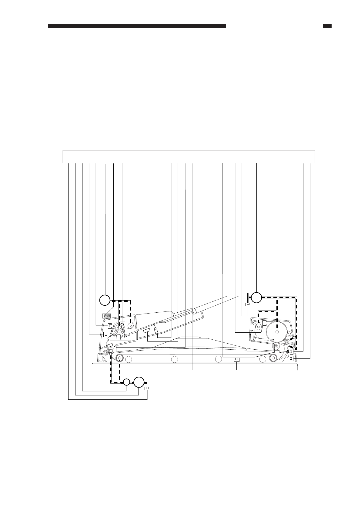
G. Detecting an Original Jam
The ADF uses the following sensors to check for original jams. The timing at which checks are
made is stored in advance in the CPU (Q1) on the ADF controller PCB, and a jam is identified in
relation to the presence/absence of paper over a specific sensor.
In response to a jam, the ADF communicates to the copier in the form of a code, which may be
checked in the copier’s service mode (COPIER>DISPLAY>JAM).
Service Mode Screen (copier)
Display
< JAM >
AA BBBB CCCC DDDD E FFFF G HHHHHH IIIII
AA BBBB CCCC DDDD E FFFF G HHHHHH IIIII
AA BBBB CCCC DDDD E FFFF G HHHHHH IIIII
AA BBBB CCCC DDDD E FFFF G HHHHHH IIIII
AA BBBB CCCC DDDD E FFFF G HHHHHH IIIII
AA BBBB CCCC DDDD E FFFF G HHHHHH IIIII
AA BBBB CCCC DDDD E FFFF G HHHHHH IIIII
AA BBBB CCCC DDDD E FFFF G HHHHHH IIIII
I/O
Adjust
Function
< 1/7 > < READY >
Option Test
+/-
'1' indicates that
the jam is in the ADF.
OK
Jam code
Counter
Figure 2-278
SR3
U503
SR2
U504
SR8
U505
SR2...... pickup unit cover sensor
SR3...... separation sensor
SR4...... reversal inlet sensor
SR5...... reversal registration sensor/
delivery sensor
SR6...... ADF open/closed sensor
SR8...... reversal delivery
unit cover sensor
U502....pre-registration sensor
U503....original set sensor
U504....last original sensor
U505....reversal outlet sensor
U502
U508
SR5
SR4
U508....original detecting volume
Figure 2-279
COPYRIGHT © 1999 CANON INC. CANON DADF-B1 REV.0 APR. 1999 PRINTED IN JAPAN (IMPRIME AU JAPON)
2-43
Page 60

CHAPTER 2 BASIC OPERATION
Note:
1. Response to a Jam
The ADF is stopped immediately in response to any of the jams in Table 2-207.
2. Resetting after a Jam
For a pickup delay jam, remove the originals from the original tray to reset the ADF. For other
types of jams, remove the originals from the original tray and from inside the ADF; then, open
and close the ADF to reset.
3. An alarm indication will turn on when either of the following is executed:
· mixed size operation without selecting mixed size mode
· copying stapled originals
If the original must be removed from inside the machine, both jam and alarm indications will be
turned on.
For example, the "Alarm and 8C Jam" indications may be turned on at the same time. The
alarm indication will remain for 5 sec after removal of the jam and, thereafter, the alarm will
automatically turn off.
2-44
COPYRIGHT © 1999 CANON INC. CANON DADF-B1 REV.0 APR. 1999 PRINTED IN JAPAN (IMPRIME AU JAPON)
Page 61

CHAPTER 2 BASIC OPERATION
The sensors and conditions used to identify jams are as follows:
Jam Code Sensor Condition
Separation delay 0002 SR3 The separation sensor (SR3) does not turn on within 50
Pickup delay 0003 U502 The pre-registration sensor (U502) does not turn on within 1 sec
Pickup stationary 0005 U502
Separation timing
Reversal outlet
delay
Reversal outlet stationary
Duplexing preregistration sensor
delay
Delivery inlet delay 0041 SR4 The reversal inlet sensor (SR4) does not turn on when the feed
Delivery stationary 0042 SR4 The reversal inlet sensor (SR5) does not turn off a specific time
0006 SR3
0011 U505 The reversal outlet sensor (U505) does not turn on a specific
0012 U505 The reversal outlet sensor (U505) does not turn on when the
0023 U502 The pre-registration sensor (U502) does not turn on a specific
msec after the separation motor (M1) has started to rotate.
after the original has left the separation sensor (SR3) in the
case of a small-size original or a point near the separation
sensor in the case of a large-size original.
The pre-registration sensor (U502) does not turn off when the
feed motor has rotated for 500 msec after the original was made
to arch at the registration roller.
The separation sensor (SR3) is on when separation of the
original starts.
time after the trailing edge of the original has moved past the
right edge of the belt registration roller.
delivery motor has rotated for 500 msec after the reversal registration sensor (SR5) detected the trailing edge of the original.
time after the double-sided original has been moved to the pickup unit side from the copyboard glass after it was turned over.
motor (M2) has been rotated for an equivalent of 10 mm after
the original is picked up in the case of a small-size original or
from a point 51 mm of the reversal inlet sensor (SR4) in the case
of a large-size/double-sided original.
after the leading edge of the original has reached the reversal registration roller nip in the case of a small-size original or after the
leading edge of the original has reached the reversal outlet
sensor (U505) in the case of a large-size/double-sided original.
Reversal registration delay
Reversal registration stationary
Reversal flapper
fault
Delivery sensor
delay (small-size)
Delivery sensor
stationary
(small-size)
Delivery sensor
delay (large-size,
double-sided)
0043 SR5 The reversal registrations sensor (SR5) does not turn on a
specific time after the reversal inlet sensor (SR4) has turned don.
0044 SR5 The reversal registration sensor (SR5) doe not turn off a
specific time after the reversal inlet sensor (SR4) has turned off.
0045 U505 The flapper is not switched when the reversal outlet sensor
(U505) checks the switch-over at each delivery.
0046 SR5 The delivery sensor (SR5) does not turn off within a specific time
after the reversal delivery motor (M3) has started to rotate
counterclockwise.
0047 SR5 The delivery sensor (SR5) does not turn off when the trailing
edge of the original has been fed 50 mm after it has moved past
the delivery sensor (SR5).
0048 SR4 The reversal inlet sensor (SR5) doe not turn on a specific period
after delivery has started.
Table 2-207-1
COPYRIGHT © 1999 CANON INC. CANON DADF-B1 REV.0 APR. 1999 PRINTED IN JAPAN (IMPRIME AU JAPON)
2-45
Page 62

CHAPTER 2 BASIC OPERATION
Jam Code Sensor Condition
Reversal delivery
unit cover open
ADF open 0081 SR6 The ADF is opened while the copier is at rest in the absence of
Pickup cover open 0082 SR2 The pickup unit cover is opened while the copier is at rest in the
Residual original 0088 SR4,SR5 An attempt at pickup is made with an original on the copyboard
Timing fault 1 008A When making a double-sided copy, pickup timing for the second
Timing fault 2 008B When originals are fed continuously, a second original has been
Timing fault 3 008C
User ADF open 0091 SR6 The ADF is opened while the ADF is in operation.
0080 SR8 The reversal delivery unit cover is open when the copier is at
rest in the absence of copy paper.
copy paper.
absence of copy paper.
glass. The reversal inlet sensor (SR4) and the reversal registration sensor (SR5) are used.
side fails. Or, the end of the task is not detected after a specific
time.
picked up while the delivery clock sensor (SR7) is used to check
a delivery original, not enabling detection of the encoder pulses
from the reversal delivery motor (M3).
If originals of different sizes are sent without selecting mixed size
mode, the original size error alarm (0014) will be turned on.
This jam indication is turned on to draw attention to the need of
removing the jam.
008C (jam) and 0014 (alarm) are indicated at the same time,
and the machine will reset itself automatically in 5 sec after the
removal of the jam.
User cover open 0092 SR2,SR8 The cover is opened while ADF is in operation.
Separation sensor
initial condition
Pre-registration
sensor initial condition
Reversal inlet sensor
initial condition
Reversal registration
sensor
0094 SR3 The separation sensor (SR3) is on before the first original is
separated.
0095 U502 The pre-registration sensor (U502) is on before the first original
is separated.
0096 SR4 The reversal inlet sensor (SR4) is on before the first original is
separated.
0097 SR5 The reversal registration sensor (SR5) is on before the first
original is separated.
Table 2-207-2
2-46
COPYRIGHT © 1999 CANON INC. CANON DADF-B1 REV.0 APR. 1999 PRINTED IN JAPAN (IMPRIME AU JAPON)
Page 63

CHAPTER 2 BASIC OPERATION
H. Alarm Detection
The machine's alarm code is as follows, and may be checked by making the following selection:
COPIER>DISPLAY>ALARM-1>DF
Alarm Display Screen (copier's service mode)
Display
< ALARM-1 >
DF 00
SORTER 00 00 00 00
I/O
Adjust
Function
< 1/1 > < READY >
Figure 2-280-1
Option Test
Counter
COPYRIGHT © 1999 CANON INC. CANON DADF-B1 REV.0 APR. 1999 PRINTED IN JAPAN (IMPRIME AU JAPON)
2-47
Page 64

CHAPTER 2 BASIC OPERATION
The sensors and conditions used to identify alarms are as follows:
Jam Code Sensor Condition
Separation fault 0003 SR3 When picking up the 1st sheet, the separation sensor (SR3)
Jam recovery count
error
Original extraction 0013 The original has been pulled off the tray while originals are
Original size error 0014 Originals of different sizes are used without selecting mix size
Operation mode
error
0011 The jam recovery count is higher than the number of originals.
0021
does not turn on 500 msec after the separation motor (M1) has
been rotated clockwise.
processed.
mode. Or, originals different in size by ±10 mm or more in
feeding direction have been detected.
The selected combination of operating modes cannot be
executed.
008C (jam) will also be indicated at the same time.
After the removal of the jam, the alarm (0014) will be indicated
for 5 sec; thereafter, the alarm will automatically be reset.
Figure 2-207-3
2-48
COPYRIGHT © 1999 CANON INC. CANON DADF-B1 REV.0 APR. 1999 PRINTED IN JAPAN (IMPRIME AU JAPON)
Page 65

CHAPTER 2 BASIC OPERATION
Reference:
At time of a jam, the copier remembers how may originals it has copied, and sends the
information to the ADF controller upon removal of the jam.
In response, the ADF controller circulates the originals that have been copied already, and
places the originals that have not been copied on the copyboard for copying. For this reason,
normal copying operation would not be possible if the number of originals after removal of
jams differs from the number of originals before the jam.
In the case of [1] in the following diagram, the ADF and the copier will stop to operate, treating
the condition as a “different numbers of originals.” Keep in mind, however that, in the case of
[2], normal operation will continue.
10 originals are placed
on the original tray.
The 8th
original jams.
(7 originals have been
copied)
Error [2]
The 3rd
original jams.
(2 originals have been
copied.)
Normal
The originals are put
back into order, and
placed on the original
tray (10 originals).
Error [1]
3 originals are set
on the original tray.
10 (originals) - 7 (originals that have been copied) = 3 originals
8 originals are placed
on the original tray.
10 (originals) - 2 (originals that have been copied) = 8 originals
Figure 2-280
The first 7 originals (which
have been copied) are counted, and copying starts with
the 8th original.
The number of operations
are counted, and the ADF
is stopped.
The originals are counted,
and then copying starts with
the 2nd original.
1. Resetting
To reset in response to wrong placement of originals, remove all originals from the original tray,
and place them back again. The copier will indicate a message; follow the instructions.
COPYRIGHT © 1999 CANON INC. CANON DADF-B1 REV.0 APR. 1999 PRINTED IN JAPAN (IMPRIME AU JAPON)
2-49
Page 66

CHAPTER 2 BASIC OPERATION
I. Power Supply
The following figure shows an outline of the power supply system.
The ADF is supplied with two channels of 24 V power by the copier. One line (J2) runs through
a circuit breaker (CB1) to reach various loads; the circuit breaker is designed to turn on in response to
an overcurrent threatening the ADF’s circuitry. The other line (J1F) caries power which is converted
into 5 V by a regulator (Q17) and is used by logic and sensor systems; a fuse resistor (FU1, FU2) is
provided to cut off the power in response to an overcurrent in the circuit, thereby protecting the
circuit.
Fuse resistor
24V
J2
Circuit breaker
(CB1)
Fuse resistor
(FU1)
24V
J1
Copier ADF controller PCB
Regulator
IC (Q17)
(FU2)
5V
Figure 2-281
Logic
24V
5V
5V
Break
Motor
Sensor
Sensor
2-50
COPYRIGHT © 1999 CANON INC. CANON DADF-B1 REV.0 APR. 1999 PRINTED IN JAPAN (IMPRIME AU JAPON)
Page 67

CHAPTER 3
MECHANICAL SYSTEM
I. BASIC CONSTRUCTION ...............3-1
A. External Covers .....................3-1
B. Removing the Feed Belt Unit...3-4
C. ADF Controller PCB ..............3-5
II. DRIVE SYSTEM ............................3-6
A. Removing the Pickup Unit .....3-6
B. Removing the Separation
Motor (M1) ..............................3-6
Removing the Feed Motor (M2)
C.
D. Reversal Delivery Unit ...........3-8
E. Removing the Reversal Delivery
Motor (M3) ..............................3-9
III. FEEDING SYSTEM .................. 3-10
A. Removing the Separation Pad
Assembly .............................3-10
B. Removing the Separation
Roller ....................................3-11
C. Removing the Pickup Roller . .3-12
COPYRIGHT © 1999 CANON INC. CANON DADF-B1 REV.0 APR. 1999 PRINTED IN JAPAN (IMPRIME AU JAPON)
....3-7
D. Mounting the Separation
Roller Unit ............................ 3-13
E. Removing the Reversing Roller
and Feed Roller ................... 3-14
F. Replacing the Feed Belt ......3-16
VI. SENSORS ..................................3-18
A. Removing the Original Set Sen-
sor PCB (U503)....................3-18
B. Removing the Original Set Indi-
cator LED PCB.....................3-18
C. Removing the Last Original
Sensor PCB (U504) .............3-19
D . Original Width Detecting Volume
(VR)......................................3-19
E. Removing the Pre-Registration
Sensor (U502)......................3-21
F. Removing the Reversal Outlet
Sensor (U505)......................3-21
Page 68

Page 69

CHAPTER 3 MECHANICAL SYSTEM
[1]
[2]
[5]
[4]
[3]
I. BASIC CONSTRUCTION
A. External Covers
[1]
[1] Original tray
[2] Auxiliary tray
[3] Reversal delivery unit cover
[2]
[3]
Remove the appropriate covers as follows
when cleaning, inspecting, or repairing the
inside of the machine.
1. Removing the Original Tray
1) Mark the position of the original tray in
advance (by referring to the graduations
under the fixing screw).
Figure 3-101
[6]
[1]
[2]
[1] Front cover
[2] Rear cover 1
[3] Rear cover 2
[4] ADF controller cover
[5] Timing belt cover
[6] Feed belt
[7] Pickup unit cover
[4]
[7]
[3]
[5]
Figure 3-103
2) Remove the two fixing screws [1], and
shift the original tray [2] to the front.
3) Remove the screw [4], and disconnect the
connector [5]; then, detach the grounding
wire [3].
4) Detach the original tray.
Figure 3-102
Figure 3-104
COPYRIGHT © 1999 CANON INC. CANON DADF-B1 REV.0 APR. 1999 PRINTED IN JAPAN (IMPRIME AU JAPON)
3-1
Page 70

CHAPTER 3 MECHANICAL SYSTEM
[6]
Figure 3-105
Caution:
When mounting the original tray, try
fitting the original retainer [6] into the
pickup side.
2. Removing the ADF
1) Turn off the copier.
2) Disconnect the communication cable of
the ADF from the copier.
3) Open the ADF fully.
4) Remove the two screws.
[1]
Figure 3-107
5) Shift the ADF to the rear, and lift the ADF
by holding it with both your hands.
Figure 3-106
Caution:
The foot of the hinge is equipped with a
locking mechanism, requiring you to
open the ADF fully when detaching it
from the copier.
3-2
COPYRIGHT © 1999 CANON INC. CANON DADF-B1 REV.0 APR. 1999 PRINTED IN JAPAN (IMPRIME AU JAPON)
Page 71

3. Removing the Cover
[1]
[3]
[5]
[8]
[7]
[9]
[4]
[6]
[2]
Be sure to detach the ADF from the copier
before removing the pickup unit and the
reversal delivery unit.
1) Remove the three mounting screws [2] and
the TP screw [3]; then, detach the front
cover.
2) Remove the three mounting screws [5],
and detach the rear cover 1 [4].
3) Remove the three mounting screws [7],
and detach the rear cover 2 [6].
4) Remove the two mounting screws 8, and
detach the ADF controller cover [9].
[7]
[8]
[3]
[6]
[9]
[5]
CHAPTER 3 MECHANICAL SYSTEM
■■
■ When Removing the Feed Belt
■■
Unit
1) Remove the three mounting screws [2]
and the TP screw [3]; then, detach the
front cover [1].
2) Remove the three mounting screws [5],
and detach the rear cover 1 [4].
3) Remove the three mounting screws [7],
and detach the rear cover 2 [6].
4) Remove the two mounting screws [8],
and detach the ADF controller cover [9].
[1]
[4]
[2]
Figure 3-108
Figure 3-108-1
COPYRIGHT © 1999 CANON INC. CANON DADF-B1 REV.0 APR. 1999 PRINTED IN JAPAN (IMPRIME AU JAPON)
3-3
Page 72

CHAPTER 3 MECHANICAL SYSTEM
B. Removing the Feed Belt Unit
■■
■ When Removing the Pickup Unit and
■■
the Reversal Delivery Unit
1) Remove the mounting screw [2], and
detach the timing belt cover.
[2]
■■
■ When Removing the Feed Belt Unit
■■
1) Remove the mounting screw [2], and
detach the timing belt cover.
[1]
Figure 3-109
2) Remove the four stop clips [4], and detach
the feed belt unit.
[4]
[3]
[1]
[2]
Figure 3-110-1
2) Remove the four stop screws [4], and
detach the feed belt unit [3].
[4]
[5]
Figure 3-110
Caution:
When mounting the feed belt unit, try
lifting the pickup middle guide [5]
slightly.
3-4
COPYRIGHT © 1999 CANON INC. CANON DADF-B1 REV.0 APR. 1999 PRINTED IN JAPAN (IMPRIME AU JAPON)
[3]
Figure 3-110-2
Page 73

CHAPTER 3 MECHANICAL SYSTEM
[3]
[4]
C. ADF Controller PCB
1. Removing the ADF Controller PCB
Caution:
If you must remove the ADF controller
PCB as part of removing the pickup unit
or the reversal delivery unit, be sure to
remove the ADF from the copier first.
1) Remove the two mounting screws [2], and
detach the ADF controller cover [1].
3) Remove the two screws [4], and detach the
ADF controller PCB [3].
Figure 3-112
[1]
[2]
Figure 3-111
2) Disconnect all connectors from the ADF
controller PCB [3].
Caution:
Do not touch the connectors of the ADF
controller PCB unless necessary.
2. Mounting the ADF Controller PCB
When mounting the ADF controller cover,
take care so that the harness shown in the figure
will not be trapped by the cover.
Figure 3-113
COPYRIGHT © 1999 CANON INC. CANON DADF-B1 REV.0 APR. 1999 PRINTED IN JAPAN (IMPRIME AU JAPON)
3-5
Page 74

CHAPTER 3 MECHANICAL SYSTEM
II. DRIVE SYSTEM
A. Removing the Pickup Unit
Be sure to remove the ADF from the
copier before removing any parts of the drive
system.
1) Remove the original tray. (See A.
“External Covers” under I. “Basic
Construction.”)
2) Remove the body covers. (See A.
“External Covers” under I. “Basic
Construction.”)
3) Remove the feed belt unit. (See B.
“Removing the Feed Roller Unit” under I.
“Basic Construction.”)
4) Remove the ADF controller PCB. (See C.
“Removing the ADF Controller PCB”
under I. “Basic Construction.”)
5) Remove the seven mounting screws [2],
and detach the pickup unit [1].
To do so, lift the pickup unit cover side at
an angle, and put your hand underneath to
pull out the cable from the groove while
detaching it.
B. Removing the Separation
Motor(M1)
1) Remove the three mounting screws [2].
2) Disconnect the connector connected to the
harness guide [1].
3) Shift the harness guide [1] upward.
[2]
[1]
(M1)
Figure 3-202
[2]
[1]
4) Detach the timing belt from the separation
motor [3].
5) Remove the two screws [4], and detach the
separation motor [3].
[3]
[4]
Figure 3-201
Figure 3-203
3-6
COPYRIGHT © 1999 CANON INC. CANON DADF-B1 REV.0 APR. 1999 PRINTED IN JAPAN (IMPRIME AU JAPON)
Page 75

CHAPTER 3 MECHANICAL SYSTEM
C. Removing the Feed Motor (M2)
1) Remove the harness guide. (See Figure 3-
202.)
2) Remove the three mounting screws [2],
and detach the motor unit [1] of the pickup
assembly.
[2]
[1]
Figure 3-204
4) Remove the encoder plate [5] of the feed
motor while opening the claw used to keep
it in place.
[5]
Figure 3-206
5) Detach the timing belt [9] of the feed
motor, and detach the relay gear [6].
6) Remove the four mounting screws [8], and
detach the feed motor [7].
3) Remove the mounting screw [4], and
detach the feed motor clock sensor [3].
[3]
[4]
Figure 3-205
[7]
[8]
[9]
[6]
Figure 3-207
COPYRIGHT © 1999 CANON INC. CANON DADF-B1 REV.0 APR. 1999 PRINTED IN JAPAN (IMPRIME AU JAPON)
3-7
Page 76

CHAPTER 3 MECHANICAL SYSTEM
Caution:
The feed motor has its own orientation.
When mounting it, check to make sure
that it is oriented with the harness as
shown.
Figure 3-207-1
D. Reversal Delivery Unit
1. Removing the Reversal Delivery Unit
1) Remove the screw [2] used to keep the
support shaft of the delivery cover [1] in
place, and push the support shaft to detach
the delivery cover while pulling it to the
front.
[1]
[2]
Figure 3-208
2) Remove the ADF controller PCB.
3) Fit the connector on the reversal delivery
unit side into the groove.
4) Remove the five mounting screws [4], and
detach the reversal delivery unit [3].
[4]
[3]
3-8
Figure 3-209
COPYRIGHT © 1999 CANON INC. CANON DADF-B1 REV.0 APR. 1999 PRINTED IN JAPAN (IMPRIME AU JAPON)
Page 77

CHAPTER 3 MECHANICAL SYSTEM
2. Mounting the Reversal Delivery Unit
When mounting the reversal delivery unit
to the feeder, take care so that the unit will not
interfere with the plastic film shown in the
figure.
If deformed, the plastic film [1] can cause
jams in the reversal delivery assembly.
[4]
[3]
[1]
E. Removing the Reversal
Delivery Motor (M3)
1) Remove the reversal delivery unit.
2) Remove the two mounting screws of the
harness guide [1].
3) Disconnect the connectors connected to
the reversal delivery motor and the reversal
delivery motor clock sensor.
4) Remove the two mounting screws [4], and
detach the reversal delivery motor [3].
[2]
[3]
[4]
Figure 3-209-1
[2]
Figure 3-210
COPYRIGHT © 1999 CANON INC. CANON DADF-B1 REV.0 APR. 1999 PRINTED IN JAPAN (IMPRIME AU JAPON)
3-9
Page 78

CHAPTER 3 MECHANICAL SYSTEM
III. FEEDING SYSTEM
A. Removing the Separation
Pad Assembly
1) Set bits 3, 5, and 6 of the DIP switch on the
ADF controller PCB to ON (lifter ascent
mode).
O
F
F
1
2
3
4
5
6
7
8
Figure 3-301
2) Press the push switch. (In about 3 sec, the
lifter will move up and stop automatically.)
3) Close the feeder.
4) Remove the two mounting screws [2], and
detach the separation roller cover [1].
ON
5) Check to make sure that the separation
roller holder is as shown.
Figure 3-301-2
6) Release the guide roll [3] in upward
direction with a flat-blade screwdriver or
tweezers, and remove it.
[3]
[2]
[1]
Figure 3-301-1
Figure 3-302
7) Remove the two screws [5], and detach the
separation pad assembly [4].
[4]
[5]
Figure 3-302-1
3-10
COPYRIGHT © 1999 CANON INC. CANON DADF-B1 REV.0 APR. 1999 PRINTED IN JAPAN (IMPRIME AU JAPON)
Page 79

CHAPTER 3 MECHANICAL SYSTEM
8) Remove the separation pad [6].
[6]
Figure 3-302-2
9) After mounting the separation pad, be sure
to shift bits 3 and 6 of the DIP switch to
ON, and press the push switch (lifter
descent mode; in about 3 sec, the lifter will
move down and stop automatically).
B. Removing the Separation
Roller
1) Remove the separation pad assembly.
2) Move down the separation roller holder
[1], and pull off the stopper [2] as shown.
[1]
[2]
Figure 3-303
3) Move the separation roller coupling [3]
and the separation bushing [4] to the left
with tweezers.
[3]
[4]
Figure 3-303-1
COPYRIGHT © 1999 CANON INC. CANON DADF-B1 REV.0 APR. 1999 PRINTED IN JAPAN (IMPRIME AU JAPON)
3-11
Page 80

CHAPTER 3 MECHANICAL SYSTEM
4) Move down the separation roller holder in
the direction of the arrow [A], and pull the
separation roller unit to the front.
[7]
[A]
Figure 3-304
C. Removing the Pickup Roller
1) Remove the separation unit. (See A.
“Removing the Pickup Roller.”)
2) Remove the E-ring [1] used to keep the
shaft in place.
Then, pull off the shaft [2], and detach the
pickup roller [3].
[3]
[2]
5) Remove the E-ring [5] used to keep the
shaft in place, and pull off the shaft pin [6].
Then, pull off the shaft [7], and detach the
separation roller [8].
[8]
[6]
[5]
[7]
[1]
Figure 3-306
3-12
Figure 3-305
COPYRIGHT © 1999 CANON INC. CANON DADF-B1 REV.0 APR. 1999 PRINTED IN JAPAN (IMPRIME AU JAPON)
Page 81

CHAPTER 3 MECHANICAL SYSTEM
D. Mounting the Separation
Roller Unit
1) While paying attention to the position of
the bushing, fit the separation roller unit
into the pickup unit.
[3]
Figure 3-307
4) Pick the tip of the coupling [3] with
tweezers, slide it to the right, and engage it
with the separation roller shaft.
5) While holding the tip of the coupling to the
right with tweezers, rotate the separation
roller [4] in the direction shown in the
figure to engage the spring pin and the
coupling.
Figure 3-308
2) Check to make sure that the separation
roller holder lever is under the joint shown
in the figure.
Figure 3-307-1
3) Move the bushing [2] to the right.
6) Move the separation roller holder [5] in the
direction of [A] in the figure.
7) Fit in the stopper [7].
[5]
[A]
[6]
Figure 3-309
Caution:
Be sure to mount the stopper from above
the separation roller holder lever.
COPYRIGHT © 1999 CANON INC. CANON DADF-B1 REV.0 APR. 1999 PRINTED IN JAPAN (IMPRIME AU JAPON)
3-13
Page 82

CHAPTER 3 MECHANICAL SYSTEM
8) Move the stopper up and down slightly to
make sure that the stopper is in the groove
of the separation roller coupling.
Figure 3-309-1
9) After mounting the separation pad or the
separation roller, be sure to shift bits 3 and
6 of the DIP switch to ON, and press the
push switch (lifter descent mode; in about
3 sec, the lifter will move down and stop
automatically).
E. Removing the Reversing
Roller and Feed Roller
1) Remove the reversal delivery unit. (See E.
“Removing the Reversal Delivery Unit”
under II. “Drive System.”)
2) Remove the reversal delivery motor. (See
E. “Removing the Reversal Delivery
Motor” under II. “Drive System.”)
3) Remove the E-rings [1] and [2] used to
keep the two gears in place; then, remove
the E-ring [3] used to keep the main shaft
in place.
Pull off the shaft pin [4] from the main
shaft, and detach the two gears [5] and [6].
[6]
[2]
[3]
[5]
Figure 3-310
[4]
[1]
3-14
COPYRIGHT © 1999 CANON INC. CANON DADF-B1 REV.0 APR. 1999 PRINTED IN JAPAN (IMPRIME AU JAPON)
Page 83

CHAPTER 3 MECHANICAL SYSTEM
4) Remove the grip ring [7] used to keep the
gear in place. Remove the gear [9], and
remove the E-ring [8] used to keep the
shaft in place.
[8]
[9]
Figure 3-311
7) Remove the three mounting screws [14],
and detach the gear cover [13].
[7]
[13] [14]
Figure 3-313
8) Pull off the shaft pin from the shaft of the
reversing roller, and detach the reversing
roller [16].
5) Remove the spring [10] of the middle
guide.
6) While lifting the middle guide unit [11],
shift the reversing roller [12] together with
its shaft in the direction of the arrow to
detach.
[11]
[10]
[12]
[15]
[16]
Figure 3-314
Figure 3-312
COPYRIGHT © 1999 CANON INC. CANON DADF-B1 REV.0 APR. 1999 PRINTED IN JAPAN (IMPRIME AU JAPON)
3-15
Page 84

CHAPTER 3 MECHANICAL SYSTEM
9) Remove the E-rings [17] and [18] used to
keep the shaft of the feeding roller in place.
10) Remove the bushings [19] and [20] from
both ends, and detach the feeding roller
[21].
[19]
[17]
[21]
[18] [20]
Figure 3-315
F. Replacing the Feed Belt
1) Remove the feed belt unit. (See B.
“Removing the Feed Belt Unit” under I.
“Basic Construction.”)
2) Remove the two springs [1] from both
ends of the feed belt unit.
[1]
Figure 3-316
3) Pull out the feed belt [2].
Figure 3-317
[2]
3-16
COPYRIGHT © 1999 CANON INC. CANON DADF-B1 REV.0 APR. 1999 PRINTED IN JAPAN (IMPRIME AU JAPON)
Page 85

Caution:
The retaining rolls of the feed belt unit
exert different degrees of spring pressure,
with the one with a gold-colored spring
exerting greater pressure than the one
with a silver-colored spring.
Check to make sure that the correct roll is
used for each location; there are three
types of springs:
[3] : gold-colored spring (2 pc.)
[4] : silver-colored spring (4 cp.)
[3] : other than [4]; silver-colored spring
(8 pc.)
[4]
CHAPTER 3 MECHANICAL SYSTEM
Figure 3-318
[3]
COPYRIGHT © 1999 CANON INC. CANON DADF-B1 REV.0 APR. 1999 PRINTED IN JAPAN (IMPRIME AU JAPON)
3-17
Page 86

CHAPTER 3 MECHANICAL SYSTEM
VI. SENSORS
A. Removing the Original Set
Sensor PCB (U503)
1) Remove the pickup unit. (See A.
“Removing the Pickup Unit.” under II.
“Drive System.”)
2) Shift the harness guide. (See Figure 3-
302.)
3) Remove the mounting screw [2], and
detach the mounting stay [1] of the
original set sensor PCB.
4) Disconnect the connector [5].
5) Remove the two mounting screws [4], and
detach the original set sensor PCB [3].
[2]
B. Removing the Original Set
Indicator LED PCB
1) Remove the pickup unit. (See A.
“Removing the Pickup Unit” under II.
“Drive System.”)
2) Disconnect the connector [3].
3) Remove the mounting screw [2], and
detach the original set indicator LED PCB
[1].
[2]
[3]
[1]
[3]
[4]
Figure 3-401
[5]
[1]
Figure 3-402
3-18
COPYRIGHT © 1999 CANON INC. CANON DADF-B1 REV.0 APR. 1999 PRINTED IN JAPAN (IMPRIME AU JAPON)
Page 87

CHAPTER 3 MECHANICAL SYSTEM
C. Removing the Last Original
Sensor PCB (U504)
1) Remove the original tray. (See 1.
“Removing the Original Tray” under I.
“Basic Construction.”)
2) Remove the two mounting screws [2], and
detach the original tray cover [1].
[2]
[1]
D. Original Width Detecting
Volume (VR)
1. Removing the Original Width
Detecting Volume
1) Remove the original tray. (See 1.
“Removing the Original Tray” under I.
“Basic Construction.”)
2) Remove the cover of the original tray. (See
C. “Removing the Last Original Sensor
PCB (U504).”
3) Disconnect the connector [3].
4) Remove the screw [5], and remove the
grounding wire [4].
5) Remove the two mounting screws [2], and
detach the original width detecting volume
PCB [1].
[2]
Figure 3-403
3) Disconnect the connector [5].
4) Remove the two mounting screws [4], and
detach the last original sensor PCB [3].
[4]
[3]
[5]
[5]
[4]
[1]
[3]
Figure 3-405
figure 3-404
COPYRIGHT © 1999 CANON INC. CANON DADF-B1 REV.0 APR. 1999 PRINTED IN JAPAN (IMPRIME AU JAPON)
3-19
Page 88

CHAPTER 3 MECHANICAL SYSTEM
2. Mounting the Original Width
Detecting Volume
1) Remove the width guide roll.
2) Move the side guides to both ends.
[2]
[1]
Figure 3-406
[2]
5) Turn the volume fully in the direction of
the arrow [A], and turn it back an
equivalent of two teeth [B].
[A]
[B]
[5]
Figure 3-408
6) Mount the original width detecting volume
with two screws.
7) Mount the grounding wire, and connect
the connector.
[10]
3) Mount the volume idler gear against the
arrow marking.
4) Check to make sure that the click claw of
the side guide gear is as shown.
[4]
[3]
Figure 3-407
[8]
[6]
[9]
[7]
Figure 3-409
8) Mount the covers and the width guide roll;
then, mount the original pickup tray to the
feeder.
9) Perform original tray width adjustment
discussed in B. “Electrical System” under
I. “Standard and Adjustments” in Chapter 5.
3-20
COPYRIGHT © 1999 CANON INC. CANON DADF-B1 REV.0 APR. 1999 PRINTED IN JAPAN (IMPRIME AU JAPON)
Page 89

CHAPTER 3 MECHANICAL SYSTEM
[3]
[2]
[1]
[4]
E. Removing the Pre-Registration
Sensor (U502)
1) Remove the pickup unit. (See A.
“Removing the Pickup Unit” under II.
“Drive System.”)
2) Remove the two mounting screws [2], and
detach the pickup lower cover [1].
[1]
Figure 3-410
[2]
F. Removing the Reversal
Outlet Sensor (U505)
1) Remove the reversal delivery unit. (See E.
“Removing the Reversal Delivery Unit”
under II. “Drive System.”)
2) While pushing down the reversal inside
guide [1] with your finger, remove the
mounting screw [3].
3) Slide the reversal outlet sensor PCB [2]
halfway up; then, disconnect the connector
[4].
3) Open the pickup unit cover; then, remove
the two mounting screws [2], and detach
the pre-registration sensor PCB mounting
stay [1].
4) Disconnect the connector [5]; then,
remove the two mounting screws [4], and
detach the pre-registration sensor PCB [3].
[3]
[4]
[1]
[5]
Figure 3-412
[2]
Figure 3-411
COPYRIGHT © 1999 CANON INC. CANON DADF-B1 REV.0 APR. 1999 PRINTED IN JAPAN (IMPRIME AU JAPON)
3-21
Page 90

Page 91

CHAPTER 4
MAINTENANCE AND SERVICING
I. PERIODICALLY REPLACED
PARTS ........................................ 4-1
CONSUMABLES AND
II.
DURABLES..................................
COPYRIGHT © 1999 CANON INC. CANON DADF-B1 REV.0 APR. 1999 PRINTED IN JAPAN (IMPRIME AU JAPON)
4-1
III. SCHEDULED SERVICING
CHART........................................4-2
Page 92

Page 93

CHAPTER 4 MAINTENANCE AND SERVICING
I. PERIODICALLY REPLACED PARTS
The ADF does not have parts that must be replaced on a periodical basis.
II. CONSUMABLES AND DURABLES
Some parts of the ADF need replacement once or more over the period of product guarantee
because of deterioration or damage. Replace them when they prove to be faulty.
As of March. 1999
No.
1
2
3
4
Parts
Feed belt
Separation roller
Separation pad
Pickup roller
Parts No.
FB4-6934
FB5-0466
FF5-9160
FB4-1151
Q’ty
1
1
1
1
Life (copier) Remarks
120,000
180,000
60,000
120,000
Replace it dirt cannot be removed.
Based on the actual number of
sheets dealt with.
Tale 4-201
Note:
The above values do not indicate the copier’s counter readings, but the actual numbers of sheets
that have been deal with. Further, they are estimates only and are subject to change based on
future data.
Be sure to check this reading (actual number) in the copier's service mode:
COPIER>COUNTER>FEEDER-FEED. (For details, see B-4 "COUNTER" in Chapter 5.)
COPYRIGHT © 1999 CANON INC. CANON DADF-B1 REV.0 APR. 1999 PRINTED IN JAPAN (IMPRIME AU JAPON)
4-1
Page 94

CHAPTER 4 MAINTENANCE AND SERVICING
III. SCHEDULED SERVICING CHART
Caution:
Do not use solvents or oils not shown herein.
:Clean :Replace :Lubricate :Adjust :Inspect
Scheduled servicing
No.
1
2
3
4
5
6
7
8
Last original sensor (U504)
Pre-registration sensor (U502)
Pickup roller
Registration roller
Feed roller
Reversal delivery roller
Retaining roll
Drive roller
Parts
every 60,000
or 6 mon
every 60,000
or 1 yr
every 120,000
copies
Remarks
Remove the sensor, and
dry wipe it.
Clean with alcohol
when replacing the feed
belt (120,000 copies).
[4]
[2]
[3]
[8]
Table 4-301
[1]
Figure 4-301
[5]
[6]
[7]
4-2
COPYRIGHT © 1999 CANON INC. CANON DADF-B1 REV.0 APR. 1999 PRINTED IN JAPAN (IMPRIME AU JAPON)
Page 95

CHAPTER 5
TROUBLESHOOTING
I. STANDARDS AND ADJUST-
MENTS........................................5-1
A. Mechanical System................5-1
B. Electrical System ................... 5-4
II. TROUBLESHOOTING................5-9
A. Troubleshooting
Malfunctions......................... 5-10
III. ARRANGEMENT OF THE ELEC-
TRICAL PARTS ........................ 5-12
A. Motors, Solenoids, and
Sensors................................5-12
B. PCBs....................................5-14
COPYRIGHT © 1999 CANON INC. CANON DADF-B1 REV.0 APR. 1999 PRINTED IN JAPAN (IMPRIME AU JAPON)
IV. VARIABLE RESISTORS (VR),
LIGHT-EMITTING DIODES, AND
CHECK PINS BY PCB ............. 5-15
A. ADF Controller PCB ............ 5-15
B. Sensor PCBs ....................... 5-16
C. Indicator PCB.......................5-18
V. SERVICE MODE AND DIP
SWITCH.................................... 5-19
A. Outline..................................5-19
B. Service Mode .......................5-20
C. Using the DIP Switch ...........5-28
VI. SELF DIAGNOSIS .................... 5-32
A. ADF Self Diagnosis ............. 5-32
Page 96

Page 97

CHAPTER 5 TROUBLESHOOTING
< 1/1 > < READY >
DOCST
DOCST-RP
Display
Adjust
Function
Option Test
Counter
I/O
150mm
L2
Horizontal size plate
Copy paper
L1 may be anywhere as long as
it is on the copy paper.
*
I. STANDARDS AND
ADJUSTMENTS
A. Mechanical System
The major adjustments of the ADF are
made using its host copier's service mode. For
all adjustments using the DIP switch on the
ADF controller PCB, see V.C. "DIP Switch
Functions."
1 Selecting Service Mode
1) Press the User Mode key '
control panel.
2) Press '2' and '8' on the keypad at the same
time.
3) Press the User Mode key '
· The display will show the following
screen.
COPIER
FEEDER
SORTER
COPIER copier service mode
FEEDER ADF service mode
SORTER finisher service mode
FAX fax service mode
' on the
' once again.
2 Correcting the Original Skew
1) Set the copier to service mode.
2) Select FEEDER>ADJUST>DOCST (for
functions).
Figure 5-101-1
3) Place one original (A3 or 11x17) on the
original tray, and press 'OK'.
The original will be moved to and stopped
on the copyboard glass.
4) Open the ADF, and check the position of
the original on the copyboard glass.
Check to make sure that the difference
between L1 and L2 in the figure is 1 mm or
less.
FAX
Figure 5-101
Figure 5-102
COPYRIGHT © 1999 CANON INC. CANON DADF-B1 REV.0 APR. 1999 PRINTED IN JAPAN (IMPRIME AU JAPON)
5-1
Page 98

CHAPTER 5 TROUBLESHOOTING
5) If the difference is not as indicated, loosen
the nut found at the rear of the right hinge
unit.
Right hinge unit
Figure 5-103
Adjusting screw
6) Make adjustments by turning the adjusting
screw (hex) so that 1 to 2 is as indicated.
Adjusting screw
Right hinge unit
Hex driver
Figure 5-104
Relationship between and 2 and the
Adjusting Screw
Direction of rotation Relationship between
and
Clockwise direction
Counterclockwise
direction
1
< 2*
1
<
1
2
2
Right hinge unit
Figure 5-103-1
Nut
Hex driver
Range: ±2.0 mm
(The adjusting screw may be given a
maximum of 2 turns.)
The feeder will not move; after turning the
adjusting screw, be sure to move the feeder
by hand.
Table 5-101
7) After adjustment, tighten the nut to secure
the adjusting screw in place.
5-2
COPYRIGHT © 1999 CANON INC. CANON DADF-B1 REV.0 APR. 1999 PRINTED IN JAPAN (IMPRIME AU JAPON)
Page 99

CHAPTER 5 TROUBLESHOOTING
3 Adjusting the Position of the
Reversal Delivery Flapper
If a double-sided original tends to jam or
fold into a Z in the duplexing feeding
assembly, adjust the position of the reversal
delivery flapper as follows:
1) Remove the four mounting screws, and
detach the front cover. (See A. "External
Covers" under I. "Basic Construction.")
2) Open the reversal delivery unit cover [1],
and loosen the screw [2] shown in the
figure.
[1]
[2]
4) If
is not as indicated, turn the adjusting
screw [5] to adjust the position of the
reversal delivery flapper.
If it is too narrow, turn the adjusting screw
clockwise; if too wide, on the other hand,
turn it counterclockwise.
Standards:
= 0.8 to 1.3 mm
(THICKNESS GAUGE)
If is not as indicated, the following
symptoms tend to occur; be sure to make
adjustments so that it is as indicated:
· If it is less than 0.8,
double-sided originals will tend to move
askew.
· If it is more than 1.3,
originals with a bent leading edge
(downward) tend to get hooked on the
reversal inlet assembly.
5) Tighten the screw [2] of the reversal
delivery unit, and close the reversal
delivery unit cover [1].
6) Mount the front cover.
Figure 5-105
3) Open the ADF slowly, and turn the
reversal delivery roller [3]
counterclockwise in the direction of [A]
(working from where the reversal delivery
unit cover was) so that the reversal delivery
flapper [4] is as shown .
[1]
[3]
[A]
[4]
[5]
0.8 to 1.3mm
Figure 5-106-1
Figure 5-106
COPYRIGHT © 1999 CANON INC. CANON DADF-B1 REV.0 APR. 1999 PRINTED IN JAPAN (IMPRIME AU JAPON)
5-3
Page 100

CHAPTER 5 TROUBLESHOOTING
B. Electrical System
1 When Replacing the Major Parts
Major parts Work
ADF controller PCB 1. EEPROM initialization
2. Original tray width adjustment
(A/B-configuration, inch-configuration)
3. Sensor level adjustment
4. Registration position adjustment
5. Duplexing registration adjustment
Last original sensor (U504) 1. Sensor level adjustment
Original set sensor (U503)
Pre-registration sensor (U502)
Reversal outlet sensor (U505)
Original width detecting volume (U508) 1. Original pickup tray width adjustment
Table 5-103
2 EEPROM Initialization
1) Remove the ADF controller cover, and
shift bits 4, 5, and 6 of the DIP switch
(DSW1) on the ADF controller PCB to
ON.
2) Open the pickup unit cover.
O
F
F
1
2
3
4
5
6
7
8
ON
3) While holding down the push switch, turn
off and then on the copier.
This will initialize the backup data of the
EEPROM.
4) Check to make sure that LED2 is on.
5) Close the pickup unit cover, and shift all
bits of the DIP switch (DSW1) to OFF.
6) Turn off the copier; then, turn it on once
again.
Caution:
If you have replaced the ADF controller
PCB once again, be user to initialize the
EEPROM first.
5-4
Figure 5-107
COPYRIGHT © 1999 CANON INC. CANON DADF-B1 REV.0 APR. 1999 PRINTED IN JAPAN (IMPRIME AU JAPON)
 Loading...