

Page 1

Service Bulletin
Issued by Canon Europa N.V.
COPIER
Model :
Subject :
Reason :
Details :
GP605P
DIFFERENCES BET WEEN GP605P AND GP605
This bulletin is prepared to comm unicate the differences between GP605P and GP605 in view of the
introduction of the former.
1. Major Differences
• The scanner f uncti o n and A D F have be en r em o v ed ( no c opying func ti on) .
• The contr ol pane l has be en m o dif ied.
• The fro nt co v er has be en m o dif ied.
No.:
DATE:
GP605-014
(FF-T01-K1-000029-01)
10.08.99
-
1 / 15 -
Page 2
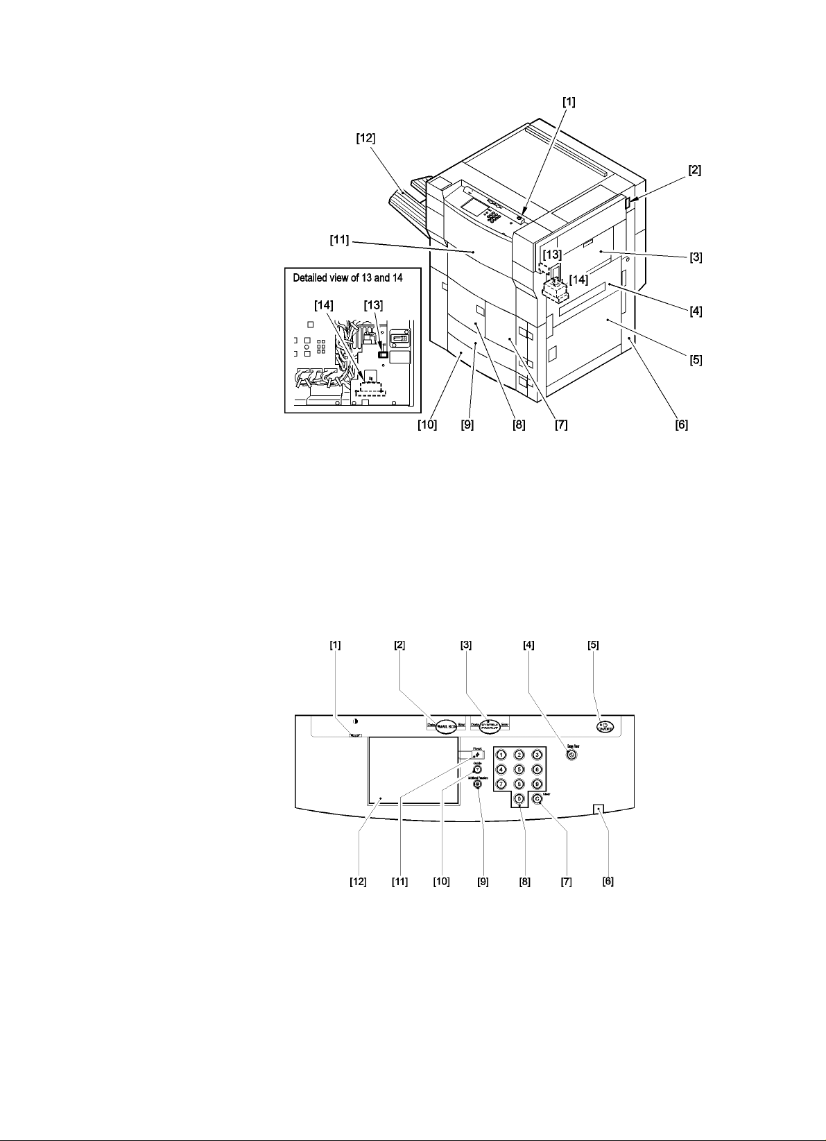
The following shows the external view and the control panel.
< External View >
GP605-014
[1] Control panel power switch [2] Main power switch
[3] Manual feed tray [4] Upper right cover
[5] Lower right cover [6] Waste toner case / drum protective sheet holder
[7] Right deck [8] Left deck
[9] Cassette 3 [10] Cassette 4
[11] Front cover [12] Delivery tray (accessory)
[13] Heater switch (cassette) [14] Leakage breaker
< Contro l Panel >
[1] Screen contrast dial [2] Mail box key
[3] SYSTEM key (may be called by a different name) [4] Save power key
[5] Control panel power key [6] Main power lamp
[7] Clear key [8] Numeric keypad
[9] User Mode key [10] Guide key
[11] Reset key [12] Touch panel
-
2 / 15 -
Page 3
2. Product Notations and Names
Voltage/country Product notation Name Type
230V/AMS
230V/FRN
230V/UK
230V/GER
230V/ITA
F135695
F135675
F135655
F135685
F135625
GP605P
GP605P
GP605P
GP605P
GP605P
3. Power Consumption (reference only)
Operating mode 230V model
Continuous printing ( W h, approx.)
Standby ( Wh, approx.)
Low power mode ( Wh, approx.)
Sleep mode ( Wh, approx.)
Power save mode ( Wh, approx.)
10% 270
25% 222
50% 159
1148
302
112
32
GP605-014
COD
BOD
DOD
AOD
FOD
4. Points to Note for Installation
• The printer board is packaged separately. Install the machine, and then install the board according
to the Installation Procedure that comes with it.
The names o f the keys on the control panel to be used under 3. "Making Checks af t er Installation"
in the Installation Procedures are as follows on the machine:
GP600 GP600P
OPTIONEN SYSTEM
OPTIONS
-
3 / 15 -
Page 4

5. Installation
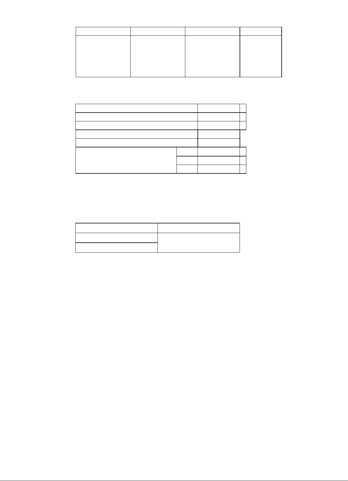
A. Unpacking
No. Work Remarks
1 Unpack the printer. Remove the two
grip covers (front, rear) on the left side,
and shift up the grips.
Grip (front)
2 Take out the grip from inside the
shipping box.
Grip
(rear)
Grip covers
Grip
GP605-014
3 Remove the grip cover (rear) from the
right side of the printer, and shift up the
grip at the rear.
4 Open the upper right door, and slide the
face cover (small) to the rear to remove;
then, detach the face cover (large).
Push in the grip removed in step 2) into
the slot at the front.
Grip
Face cover (small)
Grip
Grip covers
Face cover (large)
-
4 / 15 -
Page 5
No. Work Remarks
5 Holding the grips on the pick-up side
(front, rear), lift the printer slightly, and
remove the pad.
Likewise, holding the grips on the
delivery side, lift the printer slightly,
and remove the pad.
At this time, be sure to remove the
plastic bag.
GP605-014
6 Shift up the two adjusters (front) on the
bottom of the printer, and check to
make sure that they are unlocked.
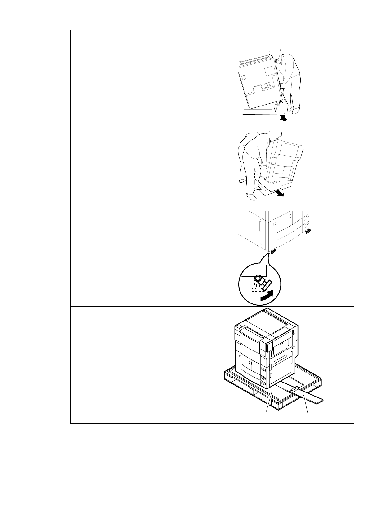
7 Take out the two slope plates stored in
the middle of the skid.
Skid
Slope plate
-
5 / 15 -
Page 6

No. Work Remarks
8 Turn over the slope plates, and match
the pin holes of the skid and the pin
holes of the slope plates; then, fit the
pins (one each).
Holding the grips (front, rear) of the
printer, slide the printer down the slope
plates off the skid.
Cautio n :
The pins are taped in place to the
slopes.
9 Open the cardboard box that comes
with the printer, and take out the parts
and sub members. Check that none of
the attachments is missing.
10 Put away the grip used in step 4) in the
compartment behind the front cover.
GP605-014
Slope plate
Front cover
Grip
11 Mount the face covers (right and left)
that have been removed.
Caution :
Before moving on to the next steps, check to see if there is condensation on the outside or the inside of the
printer right after taking it out of its shipping box. If condensation is found, stop the work and wait until the
printer has become used to the room temperature.
Start the steps that follow after making sure that the printer is free of condensation.
-
6 / 15 -
Page 7

B. Mounting the Fixi ng Assem bly
No. Work Remarks
1 Open the front door.
2 Shift down the fixing/feeding assembly
releasing lever in the direction of the
arrow (left), and unlock the
transfer/separation charging assembly.
Slide out the fixing/feeding unit to the
front.
Fixing/feeding assembly releasing lever
GP605-014
3 Remove the tag and the separation
assembly releasing member from above
the fixing/feeding assembly.
Cautio n :
Be sure to remove all traces of glue
(from tape) and foreign matter from
the feeding belt.
4 Remove the tag retaining tape, and
remove the two fixing nip releasing
screws at the front and the rear.
Fixing/feeding unit
Separation assembly
releasing member
Tape
Screws
-
7 / 15 -
Page 8

C. Mounting the Corona Assemblies
No. Work Remarks
1 Remove the screw, and detach the front
cover of the transfer separation
charging assembly.
Screw
Front cover of the transfer
separation charging assembly
2 Remove the metal fixing (1 screw), and
disconnect the connector.
Screw
While pressing down on the front and
the rear of the transfer separation
charging assembly, pull it to the front
then to the upper left to remove.
Use alcohol solution, and clean the
transfer separation charging wire.
Metal fixing
Connector
GP605-014
3 Mount the transfer separation charging
assembly with the following in mind:
• The charging assembly must be
completely dry.
• The charging wire cleaning member
is at the center.
• The gut wire is not forced against the
transfer guide.
• The grounding plate is positioned on
the outside of the frame. (See the
diagram on the right.)
4 Connect the connector of the transfer
separation charging assembly, and
mount the metal fixing.
5 Mount the front cover of the transfer
separation charging assembly with a
screw.
Push in the fixing/feeding assembly
until it locks in place.
6 Remove the screw, and detach the front
cover of the primary charging assembly.
Charging assembly
Grounding plate
Front cover of the primary charging assembly
Screw
-
8 / 15 -
Page 9

No. Work Remarks
7 Disconnect the connector and unlock
the primary charging assembly; then
Connector
Primary charging
assembly
take out the charging assembly.
Clean the primary charging wire and the
grid wire using alcohol.
Unlock
GP605-014
8 Remove the screw, and detach the front
cover of the pre-transfer charging
assembly.
9 Disconnect the connector; then, unlock
the pre-transfer charging assembly, and
take out the charging assembly.
Clean the pre-transfer charging wire
with alcohol.
Front cover of the pre-transfer
charging assembly
Screw
Connector
Pre-transfer charging assembly
Unlock
10 While keeping the lock released, push
in the primary charging assembly, and
connect the connector.
11 With the lock released, insert the
pre-transfer charging assembly fully
and slowly with care, and connect the
connector.
Cautio n :
Check to make sure that the oneway arm of the transfer charging
assembly is on top of the eccentric
cam.
12 Mount the primary charging assembly
cover and the pre-transfer charging
assembly cover with one screw each.
13 Close the front door.
One-way arm
Eccentric cam
-
9 / 15 -
Page 10

D. Checking the Developing Assembly
No. Work Remarks
1 Open the multifeeder tray, and remove
Door tape
the screw from the door tape.
2 Take out the developing assembly from
the shipping box that comes with the
printer.
Turn the developing assembly cylinder
gear by hand, and check the cylinder
surface for damage.
3 Holding the center of the developing
Developing assembly
assembly (pocket of the grip), mount it
in the printer. Then, connect two
connectors.
GP605-014
Cautio n :
When mounting the developing
assembly, try inserting it from high
above, taking care not to bring the
developing cylinder into contact
with the metal plate of the
developing assembly base.
4 Secure the developing assembly locking
unit in place with six screws (M4 6;
black; attachment).
5 Mount the door tape of the multifeeder
with a screw.
Connectors
Developing assembly locking unit
Screw
Screw
Screws
-
10 / 15 -
Page 11

E. Mounting the Pick- Up Assembly
No. Work Remarks
1 Open the multifeeder door, and shift the
lever in the direction of the arrow.
Then, take out the pick-up roller
releasing spacer.
Pick -up roller releasing spacer
2 Open the upper right door and the lower
right door. Then, push the releasing
button of the front deck (R), cassettes 3
and 4, and slide them out half way.
3 Remove the three pick-up roller
releasing spacers.
GP605-014
4 Secure the deck pressure plate to the
front deck (left) with an RS tightening
screw (M4 6; white).
Pick -up roller releasing spacers
Deck pressure plate
Screw
-
11 / 15 -
Page 12

F. Supplying Toner
No. Work Remarks
1 Take out the toner cartridge from the
Toner cartridge
packaging box.
GP605-014
2 Remove the packing tape
3 Open the hopper cover, and insert the
toner cartridge from the front of the
printer.
Cautio n :
Insert the toner cartridge until the
marking ▲ of the toner cartridge
and the marking ▼ of the printer
come into contact.
Marking
Toner cartridge
Packing tape
Hopper cover
Toner cartridge
4 Close the hopper cover.
-
12 / 15 -
Page 13

G. Checking Images/Operations (user mode)
No. Work Remarks
1 Push the releasing buttons of the
cassettes 3 and 4; then, slide out the
cassettes to the front, and remove the
packing material.
2 Set the side plates of the cassettes 3 and
4 against the holes (A4/A3) of the
Stops
marking M.
Fit the stops into the holes identified as
follows so that the bottom of the
cassette will not lift.
A: STMT-R
H: LTR-R
Cautio n :
This step applies only if the user
does not use Inch-configured paper.
GP605-014
Marking A
Marking H
3 Connect the power plug to the outlet;
then, turn on the main power switch and
the control panel power switch in
sequence.
Cautio n :
In the case of a 230V model, connect
the power plug that comes with the
unit to the printer before making
checks.
230V
4 Place paper into the cassettes according
to paper size.
5 Attach the size stickers to the paper size
plate of the cassettes.
6 Set each cassette to the printer.
• Adjust the contrast of the control panel using the control
dial on the screen. Inform the user of how the dial may be
used.
• Check that the Supply Paper indicator has turned on.
• Press the keys on the keypad and the Clear key to make
sure that the indicated is correct.
Cautio n :
If you need to change the size of the deck (R) or (L),
see H. "Changing the Size of the Front Deck (right
and left)."
-
13 / 15 -
Page 14

No. Work Remarks
7 Attach cassette size stickers to the
cassettes to suit the user's needs.
Sticker
8 If you are not installing the finisher,
mount the copy tray.
9 Start service mode.
Control Panel Key Operations
Select 'COPIER'.
↓
Select 'FUNCTION'.
↓
Select 'INSTALL'.
↓
Make sure that the notation on the
screen for service mode has changed
from ‘WAITING’ to ‘READY’; then,
↓
Select 'TONER-S'.
↓
Check that the message 'CHECK THE
DEVELOPER' is indicated.
↓
After making sure that the developing
assembly and its locking unit are
properly mounted, press the 'OK' key.
↓
The printer will start toner supply
operation (about 10 min).
↓
When the operation ends, press the
Reset key twice to end service mode.
10 Make settings for standard mode in user
mode and service mode to suit the
user's needs.
11 Press the Reset key twice to end service
mode.
12 Clean up the area around the printer.
13 Move the printer to the site of
installation, and fix the printer in place
using the adjusters.
Starting Service Mode
1. Press the User Mode key.
2. Press '2' and '8' of the keypad at the same time.
3. Press the User Mode key.
Cautio n :
Do not turn off the power while the machine i s operating .
For details of service mode, see the VIII. in chapter 13.
GP605-014
-
14 / 15 -
Page 15

No. Work Remarks
14 If you need to install accessories, install
them now according to the instructions
given in the respective Installation
Procedures.
15 Fill out the Service Sheet.
H. Changing the Size of the Front Deck (right and left)
No. Work Remarks
1 Press the releasing button, and slide out
the deck.
2 Remove the screw from the rear guide
plate, and fix the guide plate in position
to suit the new size.
Guide plate
Screw
GP605-014
3 Remove the screw (one each) from the
left and right guide plates. Then, fix the
guide plates in position to suit the new
size.
4 Put paper in the deck.
5 Attach the new size sticker to the paper
size plate of the deck.
6 Slide the deck into printer.
7 Start service mode, and register the new
paper size.
I. Mounting the Pri nt e r Boar d
No. Work Remarks
1 Take out the Printer Board from a box
packaged separately.
For mounting instructions, see the
Installation Procedure that comes with
the Printer Board.
For deck (R): COPIER>OPTION>CST>P-SZ-C1
For deck (L): COPIER>OPTION>CST>P-SZ-C2
A4: 6, B5: 15, LTR: 18
Guide plate
Screws
6. Points to Note for Servicing
• For servicing, see the Service Manual (for GP605, FY8-13F D-000). The periodically replaced
parts and durables are the sam e as those of GP605.
• For service parts, see the newly released Part s Catalog ( for GP605, FY8-31DU-00).
-
15 / 15 -
 Loading...