

Page 1

SERVICE
HANDBOOK
REVISION 0
JAN. 1999
COPYRIGHT © 1999 CANON INC. CANON 405/335 REV.0 JAN. 1999 PRINTED IN JAPAN (IMPRIME AU JAPON)
FY8-23AZ-000
Page 2

IMPORTANT
THE INFORMATION CONTAINED HEREIN IS PUBLISHED BY CANON, INC., JAPAN, AND IS
FOR REFERENCE USE ONLY. SPECIFICATIONS AND OTHER INFORMATION CONTAINED
HEREIN MAY VARY SLIGHTLY FROM ACTUAL MACHINE VALUES OR THOSE FOUND IN
ADVERTISING AND OTHER PRINTED MATTER.
ANY QUESTIONS REGARDING INFORMATION CONTAINED HEREIN SHOULD BE DIRECTED
TO THE COPIER SERVICE DEPARTMENT OF THE SALES COMPANY.
COPYRIGHT © 1999 CANON INC.
Printed in Japan
Imprimé au Japon
Use of this manual should be
strictly supervised to avoid
disclosure of confidential
information.
Prepared by
OFFICE IMAGING PRODUCTS TECHNICAL SUPPORT DEPARTMENT 1
OFFICE IMAGING PRODUCTS TECHNICAL SUPPORT DIVISION
CANON INC.
5-1, Hakusan 7-chome, Toride-shi Ibaraki, 302-8501 Japan
COPYRIGHT © 1999 CANON INC. CANON 405/335 REV.0 JAN. 1999 PRINTED IN JAPAN (IMPRIME AU JAPON)
Page 3

CONTENTS
CHAPTER 1 MAINTENANCE AND INSPECTION
1
2
A. Scheduled Servicing Table........................1-1
1. Copier ..................................................1-1
2. Paper Deck..........................................1-2
B. Periodically Replaced Parts.......................1-3
C. Consumables and Durables ...................... 1-3
1. Copier ..................................................1-3
2. Side Paper Deck..................................1-4
D. Image Basic Adjustment Procedure..........1-5
E. Points of Scheduled Servicing................... 1-6
CHAPTER 2 STANDARDS AND ADJUSTMENTS
A. Image Adjustment...................................... 2-1
B. Exposure System ......................................2-6
C. Image Formation System ..........................2-9
D. Pick-Up/Feeding System.........................2-11
E. Fixing System ..........................................2-16
F. Electrical System .....................................2-18
CHAPTER 3 ARRANGEMENT AND FUNCTIONS OF
ELECTRICAL PARTS
A. Clutches and Solenoids.............................3-2
B. Motors........................................................3-4
C. Fan.............................................................3-6
D. Sensors......................................................3-8
E. Switches and Counters............................3-10
F. PCBs........................................................3-12
G. Side Paper Deck...................................... 3-14
1. Sensors and Switches.......................3-14
2. Motors, Solenoids, and PCBs ...........3-16
H. Variable Resisters, Light-Emitting Diodes,
and Check Pins by PCB ..........................3-18
1. Image Processor PCBs
(main controller).................................3-19
2. DC Controller PCB (DC driver)..........3-21
3. Composite Power Supply CPB .........3-23
4. Deck Driver (side paper deck)...........3-24
I. Upgrading ................................................3-25
1. Removing the DIMM.......................... 3-26
2. Mounting the DIMM ...........................3-27
3. Downloading...................................... 3-28
3
4
5
i
Page 4

CHAPTER 4 SERVICE MODE
A. Outline .......................................................4-1
1. Starting Service Mode and Making
Selections ............................................ 4-1
2. Ending Service Mode .......................... 4-2
3. Backing Up the RAM ...........................4-2
4. Basic Operation ................................... 4-4
B. DISPLAY Control Display Mode................4-7
C. I/O Operation Check Mode ...................... 4-22
1. DC-CON ............................................4-23
2. IP .......................................................4-30
CHAPTER 5 SELF DIAGNOSIS
A. Copier ........................................................ 5-3
B. DADF .......................................................5-10
C. Cassette Feeding Unit-R1/S1 .................. 5-11
D. Multi Output Tray-D1 ...............................5-11
E. Finisher-C1 .............................................. 5-12
3. FEEDER ............................................ 4-31
4. SORTER (Finisher C1, Saddle
Finisher C2, Finisher E1)................... 4-34
D. ADJUST Adjustment Mode...................... 4-45
E. FUNCTION Operation Check Mode........4-53
F. OPTION Settings Mode ........................... 4-65
G. PG test Print ............................................4-73
H. COUNTER Mode ..................................... 4-78
I. FEEDER ..................................................4-81
J. SORTER (finisher, saddle stitcher) .........4-85
F. Saddle Finisher-C2 ..................................5-14
G. Finisher-E1 ..............................................5-18
H. Paper Deck-B1 ........................................5-20
I. SCSI Interface Board-D1.........................5-21
APPENDIX
A. General Timing Chart ............................... A-1
B. Signal name/abbreviation list.................... A-3
C. General Circuit Diagram ........................... A-7
D. General Circuit Diagram Paper Deck ..... A-13
E. Specifications .......................................... A-15
1. Copier ............................................... A-15
2. Paper Deck....................................... A-21
ii
Page 5
CHAPTER 1 MAINTENANCE AND INSPECTION
CHAPTER 1 MAINTENANCE AND INSPECTION
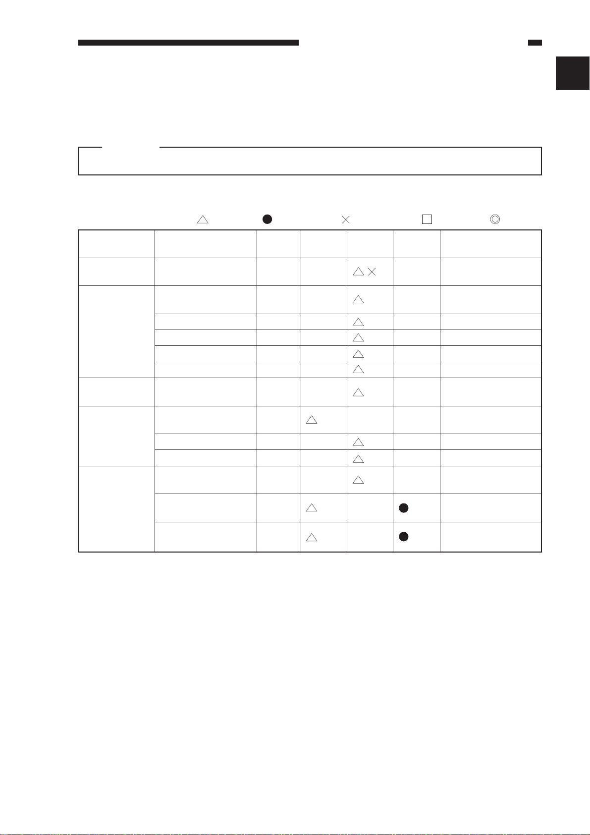
A. Scheduled Servicing Table
Caution:
Do not use solvents/oils not indicated here.
1. Copier
: Clean : Replace : Lubricate : Adjust : Inspect
Unit
Scanner drive
assembly
Optical assembly
Developing
assembly
Feeding assembly
Fixing
assembly
Part
Scanner rail
No. 1 through No. 3
mirrors
Dust-proofing glass
Lens
Reflecting plate
Original size sensor
Developing assembly
roll
Transfer guide
Feeding belt
Feeding assembly base
Fixing assembly
inlet guide
Upper separation claw
Lower separation claw
Installation
every
60,000
every
120,000
every
240,000
Remarks
Use lubricant.
Note
During a visit.
Clean as necessary.
During a visit.
Clean as necessary.
During a visit.
Clean as necessary.
1
Note: For cleaning intervals, use the hardware counter reading as a reference.
1-1
Page 6

CHAPTER 1 MAINTENANCE AND INSPECTION
2. Paper Deck
: Clean : Replace : Lubricate : Adjust : Inspect
Unit
Pick-up
assembly
Pick-up roller
Pick-up/feeding
roller
Separation roller
Feeding roller, roll
Part
Installation
Maintenance intervals
every
250,000
every
500,000
every
750,000
every
1,000,000
Remarks
1-2
Page 7

CHAPTER 1 MAINTENANCE AND INSPECTION
B. Periodically Replaced Parts
The machine does not have parts that need to be replaced on a periodical basis.
C. Consumables and Durables
1. Copier
Some parts of the machine may require replacement once or more over the period of warranty
because of wear or damage. Replace them as necessary.
As of Dec. 1998
No.
1
Pick-up roller
2
Feeding roller
3
Separation roller
4
Pick-up roller (multifeeder)
5
Separation pad (multifeeder)
6
Transfer roller
7
Separation static eliminator
8
Scanning lamp
9
Pre-exposure lamp
10
Developing cylinder
11
Upper fixing roller
12
Lower fixing roller
13
Upper fixing separation claw
14
Lower fixing separation claw
15
Fixing cleaning belt
16
Heat insulating bush
17
Fixing heater (main)
18
Fixing heater (sub)
19
Thermistor
20
Internal delivery roller
21
Internal delivery sensor
Parts name
Parts No.
FF5-4552-020
FF5-4552-020
FF5-4634-020
FB1-8581-000
FC1-9022-030
FF5-6980-000
FF5-7246-000
FH7-3314-000
FG5-6297-000
FG6-0626-000
FB5-0289-000
FB4-2867-000
FB1-7075-000
FA2-9037-000
FA3-8908-000
FB1-6823-000
FH7-4570-000
FH7-4573-000
FG6-3881-000
FB4-2901-000
FH7-7394-000
Q'ty
2
2
2
1
1
1
1
1
1
1
1
1
5
2
1
2
1
1
1
1
1
Life (copies)
120,000
120,000
120,000
240,000
240,000
240,000
240,000
240,000
240,000
480,000
240,000
240,000
240,000
240,000
160,000
240,000
360,000
360,000
240,000
240,000
500,000
Remarks
Actual copies made.
Actual copies made.
Actual copies made.
Actual copies made.
Actual copies made.
1-3
Page 8

CHAPTER 1 MAINTENANCE AND INSPECTION
2. Side Paper Deck
As of Dec. 1998
No.
1
2
3
Parts name
Side paper deck pick-up roller
Side paper deck feeding roller
Side paper deck separation roller
Parts No.
FB4-2033-000
FB4-2034-000
FB2-7777-000
Q'ty
2
2
1
Life (copies)
250,000
250,000
250,000
Remarks
Actual copies made.
Actual copies made.
Actual copies made.
1-4
Page 9
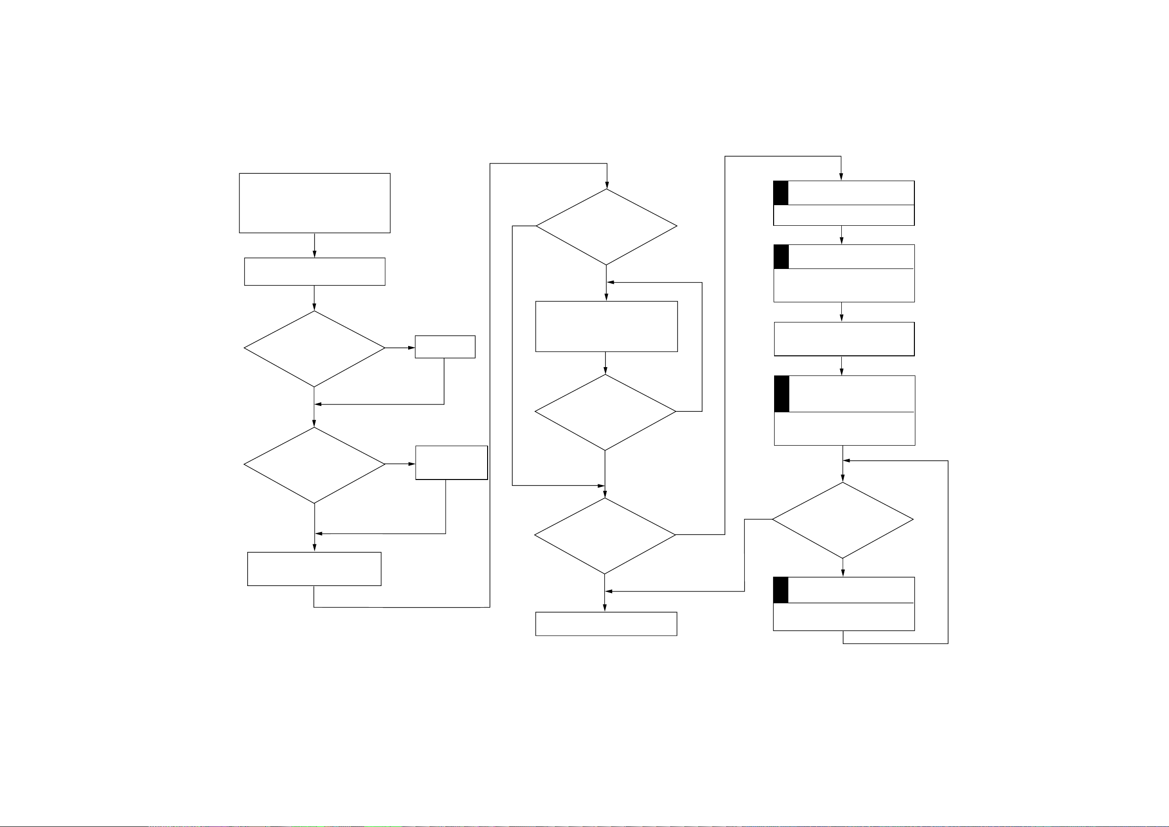
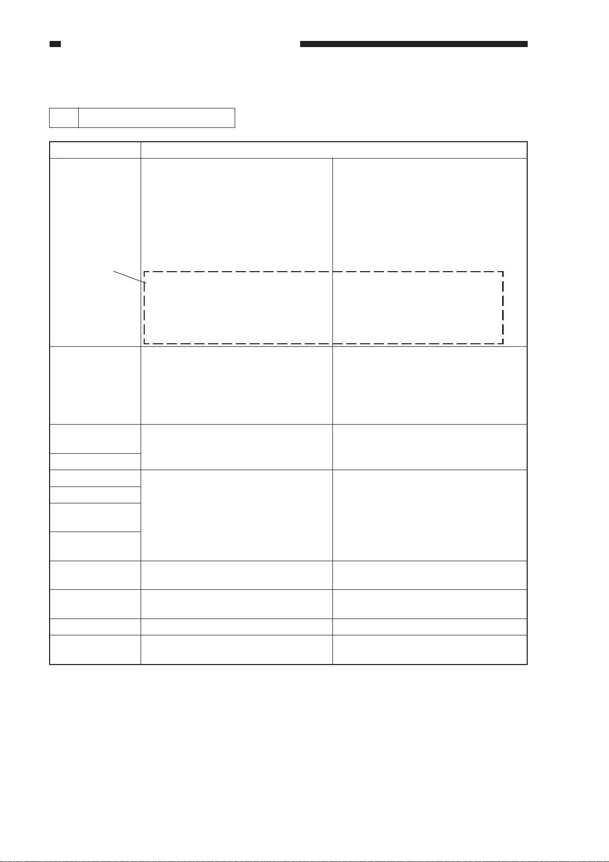
D. Image Basic Adjustment Procedure
Clean the primary charging roller
/transfer charging roller.
¥ To clean the primary/transfer
charging roller, use ’roller clean’
under ’adjustment/clean’ in user mode.
Clean the separation static
eliminator.
Is the
setting of ’density
correction’ under ’adjust/clean’
in user mode the medium
value?
YES
It the
setting of
’ADJUST’ in service
mode the value indicated on the
label attached to the
front door?
NO
Set it to the
medium value.
Enter the value
NO
indicated on the
label.
NO
Are there vertical
lines (white, black)?
YES
Clean the separation static
eliminator, dust-proofing glass,
mirrors (No. 1, No. 2, No. 3),
standard white plate, and lens.
Are the vertical lines gone?
YES
NO
Service Mode
ADJUST>DENS>DENS-ADJ
Set DENS-ADJ to 5.
Service Mode
FUNCTION>CCD>CCD-ADJ
Execute auto correction.
Open the copyboard cover or the
feeder, and make 2 solid black
copies.
Service Mode
Density Auto Adjustment
5 items under FUNCTION>DENS.
WHITE-ME, PD-DENS, PD-ME,
DZ-DENS, DZ-ME
YES
Make 2 to 3 copies in non-AE
at copy density 5.
Is the white
background foggy?
NO
End.
YES
YES
Is the fogging in the white
background gone?
NO
Service Mode
ADJUST/DENS/DENS-ADJ
Set DENS-ADJ lower than 5.
1-5
Page 10
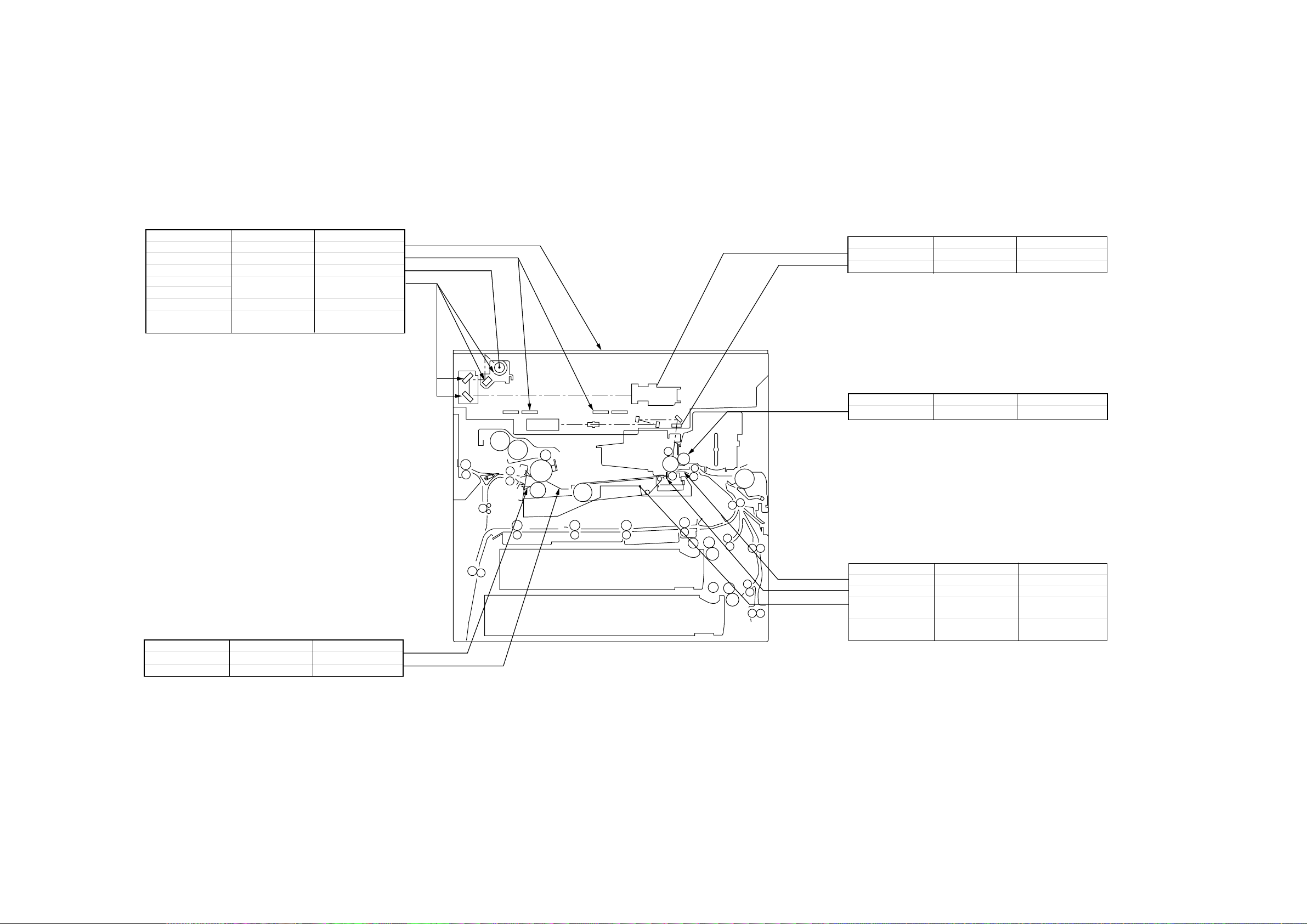
E. Points of Scheduled Servicing
Copyboard/Scanner
Item
Copyboard glass
Original size sensor
Scanning lamp
Reflecting plate
No.1 through No.3 mirrors
Standard white plate
Scanner rail
Tool/solvent
Alcohol
Blower brush
Lint-free paper
Blower brush
Alcohol
Alcohol,
Lubricant
Work/remarks
Clean.
Clean.
Dry-wipe.
As necessary, dry-wipe
with lint-free paper.
Clean
Clean, and lubricate.
Optical Assembly
Item
Lens
Dust-proofing glass
Developing Assembly
Item
Developing roll
Tool/solvent
Blower brush
Blower brush
Tool/solvent
Alcohol Clean.
Work/remarks
Work/remarks
Clean.
Clean.
Fixing/Delivery Assembly
Item
Separation
Inlet guide
Tool/solvent
Solvent
Solvent
Work/remarks
Clean.
Clean.
Transfer/Feeding/Pick-Up Assembly
Item
Transfer guide
Static eliminator
Feeding assembly
base/Feeding belt
Pick-up/feeding/
separator roller
Tool/solvent
Moist cloth*
Special brush
Moist cloth*
Alcohol
*Take care not to leave droplets of water.
Do not turn on the power before it is
completely dry.
Work/remarks
Clean.
Clean.
Clean.
Clean.
1-6
Page 11

CHAPTER 2 STANDARDS AND ADJUSTMENTS
CHAPTER 2 STANDARDS
AND ADJUSTMENTS
A. Image Adjustment
Adjust the image margin, and then the
non-image width.
Adjusting the Image Leading Edge
Margin and the Non-Image Width
a. Change the following settings in service
mode so that they are as indicated on the
service label.
• ADJUST>ADJ-XY>ADJ-X, ADJ-Y
• ADJUST>FEED-ADJ>REGIST
b. Adjusting the Image Margin
1) Put A4 or A3 paper in the cassette, and
select the cassette.
2) Select '6' in service mode (TEST>PG>
TYPE), and generate a solid black copy.
3) Make adjustments so that the margin is
2.5 ±1.5 mm.
<Main Scanning Direction>
Use the horizontal registration mount.
(See A-2.)
<Sub Scanning Direction>
Use service mode (ADJUST>FEEDADJ>REGIST; see A-1).
c. Adjusting the Non-Image Width
1) Select the cassette used for adjusting the
image margin, and make a copy of the
NA-3 Chart.
2) Make adjustments so that the leading edge
and left/right non-image widths are 2.5
mm.
<Main Scanning Direction>
ADJUST>ADJ-XY>ADJ-Y
<Sub Scanning Direction>
ADJUST>ADJ-XY>ADJ-X
2
Caution:
Be sure that the NA-3 is placed on the
copyboard glass correctly.
2-1
Page 12
CHAPTER 2 STANDARDS AND ADJUSTMENTS
Image Leading Edge Margin
(REGIST; registration roller
1
activation timing)
Standard: 2.5 ±1.5 mm
For steps see the previous page.
n COPIER>ADJUST>FEED-ADJ>
REGIST
2.5 ± 1.5mm
Figure 2-1
<Making Adjustments>
• To increase the leading edge margin,
increase the setting of REGIST (thereby
delaying the activation of the registration
roller).
• To decrease the leading edge margin,
decrease the setting of REGIST.
n After adjusting the image leading edge
margin, be sure to make adjustments
under ADJUST>ADJ-XY>ADJ-X. (See
the descriptions for service mode.)
Adjusting the Left/Right
2
Registration (front)
a. Pick-Up from the Cassette
Check to see if the margin on the image
front is 2.5 ±1.5 mm for each cassette.
( ) ( + )
2.5 1.5mm
0
2
4
6
8
10
Figure 2-2
If it is not as indicated, perform the following:
1) Slide out the cassette in question.
2) Remove the two screws [1], and detach
the horizontal registration mount.
2-2
[1]
Horizontal registration mount
Figure 2-3
Page 13
CHAPTER 2 STANDARDS AND ADJUSTMENTS
2.5mm ±2.0
Decrease ADJ-REFE.
(A decrease of 23
causes a change of
1 mm.)
Increase ADJ-REFE.
(An increase of 23
causes a change of
1 mm.)
3) Loosen the hex screw, and move the
horizontal registration plate to the front/
rear to make adjustments.
(front) (rear)
Hex screw diameter
Horizontal
registration plate
Hex screw
Left/Right Registration for the 2nd
Side of a Double-Sided/Overlay
3
Copy (rear/front direction)
Check to see if the image on the 2nd side
of a double-sided/overlay copy is as indicated.
• Standard: 2.5 mm ±2.0 mm
Figure 2-6
b. Pick-Up from the Multifeeder
4mm
Figure 2-4
Caution:
When making adjustments, match the
inside of the L angle of the horizontal
registration plate with the appropriate
graduation of the scale.
+
-
Figure 2-5
Loosen the screw, and move the tray so
that it is 2.5 ±1.5 mm in Direct mode.
If it is not as indicated, make adjustments
using the following in service mode:
COPIER>ADJUST>FEED-ADJ
>ADJ-REFE
2-3
Page 14
CHAPTER 2 STANDARDS AND ADJUSTMENTS
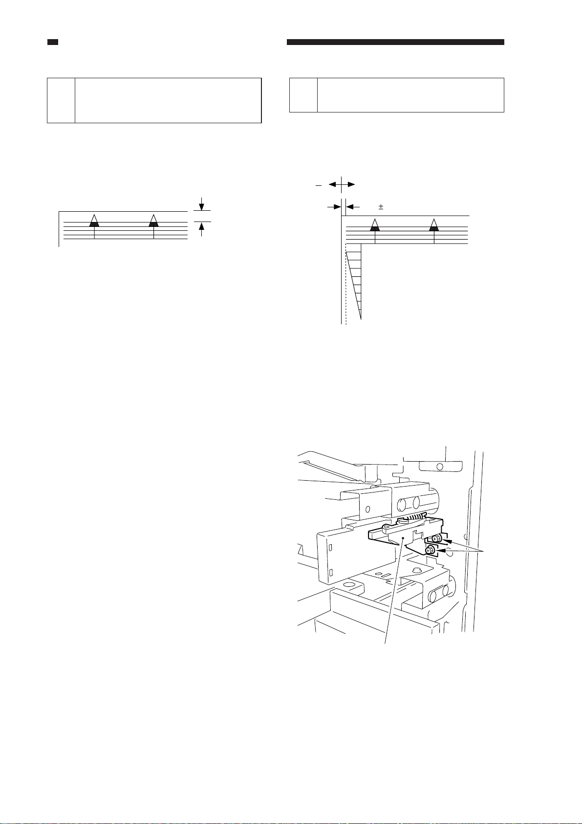
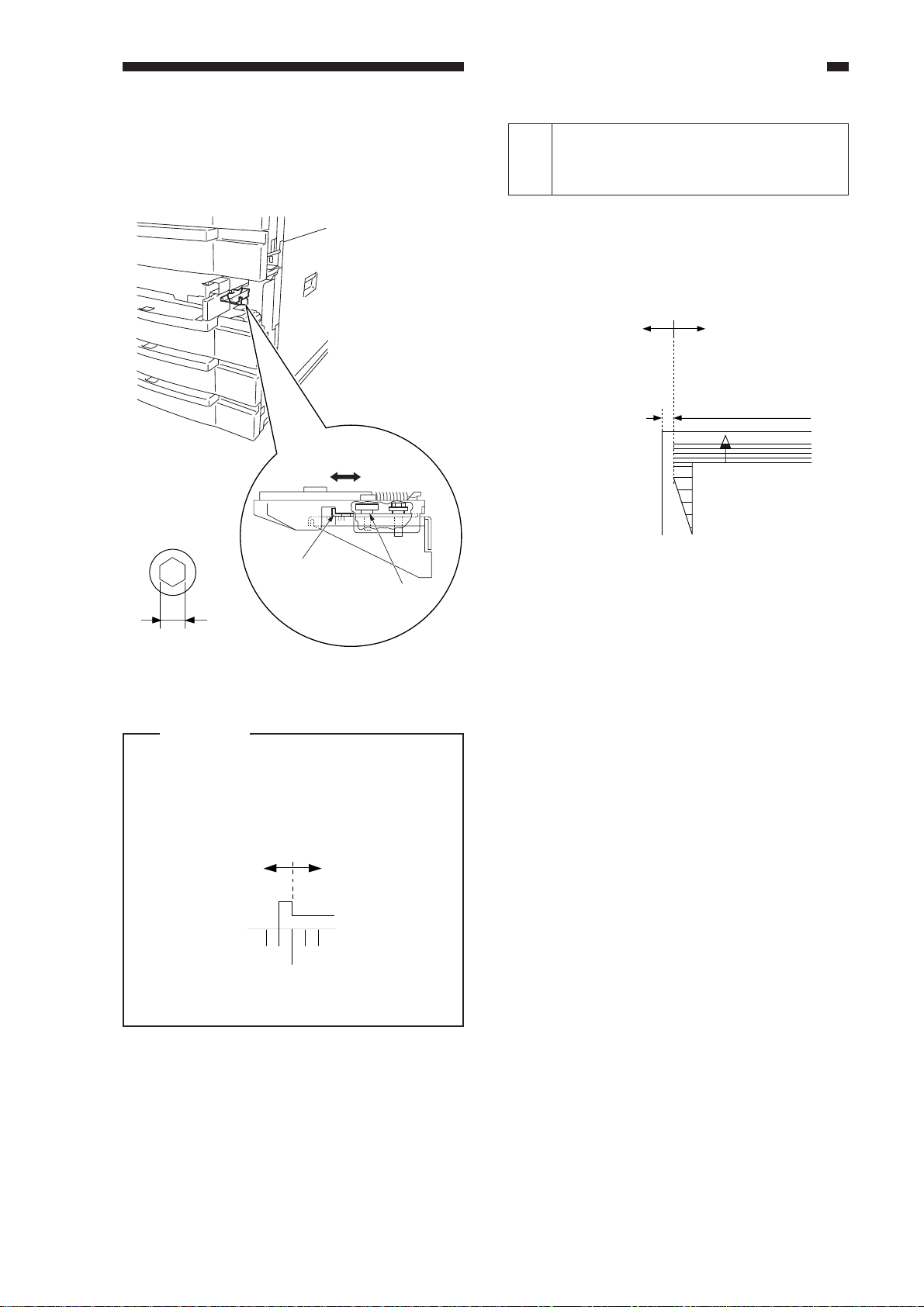
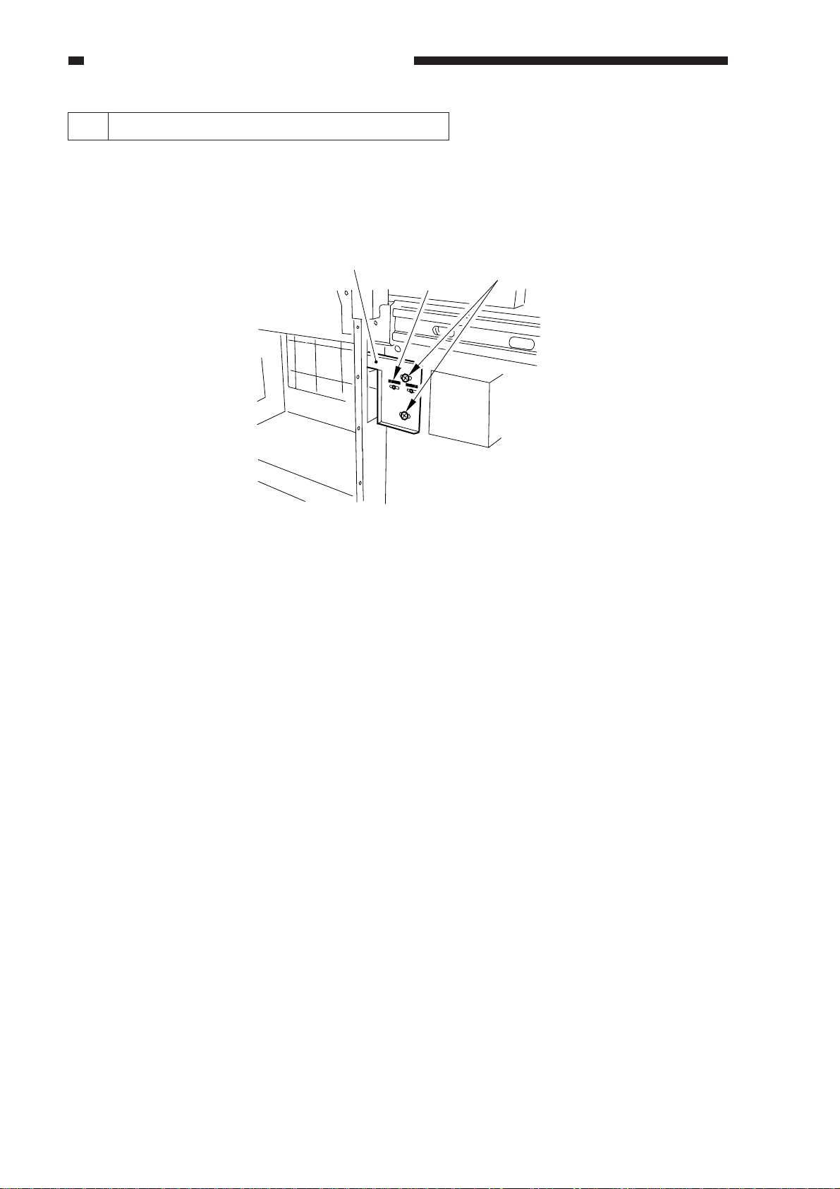
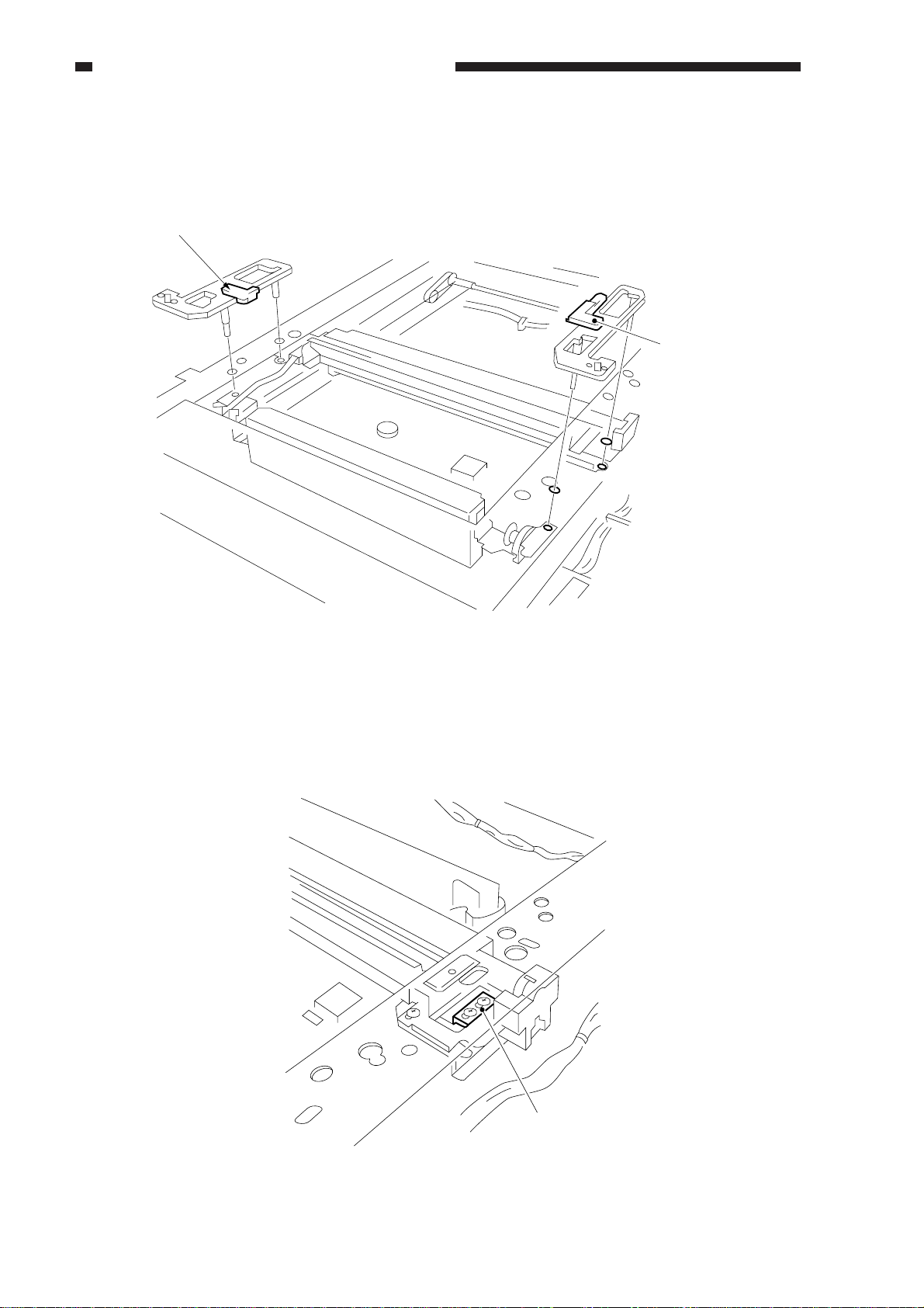
4 Left/Right Registration (side paper deck)
1) Make a copy of the Test Sheet, and check to see if the left/right registration is 0 ±1.5 mm.
2) If it is not as indicated, slide out the compartment, and turn the two screws to adjust the position
of the latch plate of the deck open solenoid. (At this time, refer to the scale on the latch plate.)
Latch plate
Scale
Screws
Figure 2-7 (rear left of the compartment)
2-4
Page 15
CHAPTER 2 STANDARDS AND ADJUSTMENTS
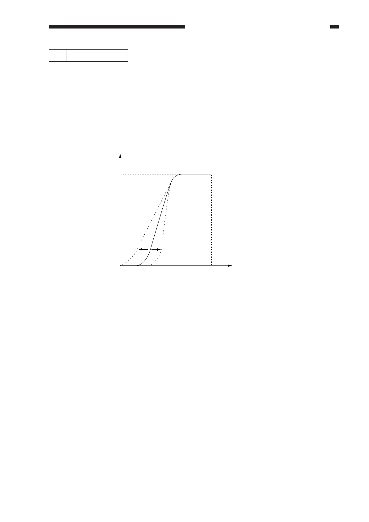
5 AE Adjustment
The machine's AE (auto density adjustment) based on "priority on speed," and its method and
concept are as follows:
1. Adjusting Priority on Speed AE Mode
ADJUST>AE>AE-TBL (1 through 9; 3 at time of shipment)
Adjust the density correction curve (text) for priority on speed AE mode.
• A higher setting makes text lighter.
• A lower setting makes text darker.
Copy density
White
Black
Higher
setting
Black
Lower setting
Original density
White
Figure 2-8
2-5
Page 16
CHAPTER 2 STANDARDS AND ADJUSTMENTS
B. Exposure System
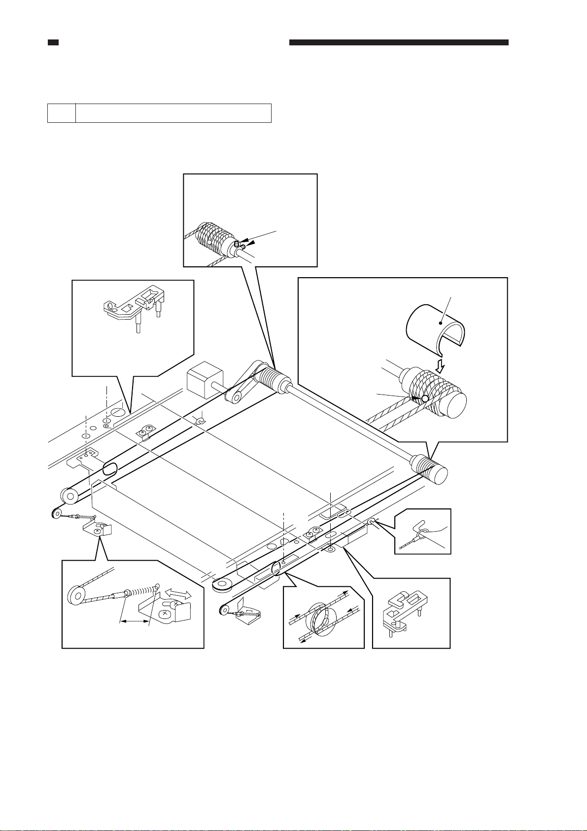
1 Routing the Scanner Drive Cable
Route the cable from [1] through [9]; then, go to the next item, "Adjusting the Mirror Position."
Loosen the set screws
to free the pulley.
Set
screws
[7]
[9]
[2]
Fit the mirror
positioning tool
[5]
Put the steel ball into the
hole in the pulley.
Wind the cable 3.5
times inwardly and
4.5 times outwardly;
then, fit the
pulley clip.
Steel ball
[8]
Pulley clip
[1]
[4]
2-6
38Å`39mm
[6]
[2][3]
Figure 2-9
Page 17
CHAPTER 2 STANDARDS AND ADJUSTMENTS
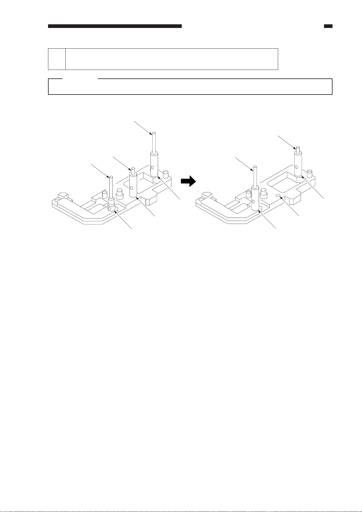
2 Adjusting the Mirror Position
(optical length between No. 1 mirror and No. 2/No. 3 mirror)
Caution:
Use the mirror position tool FY9-3009-040. Be sure to relocate the pins before use.
[C]
[B]
[C][B]
[A]
[2]
[1]
FY9-3009-040 Before Repositioning the Pins
[3]
Figure 2-10
[3]
[2]
[1]
After repositioning the Pins
2-7
Page 18
CHAPTER 2 STANDARDS AND ADJUSTMENTS
1) Loosen the screws on the metal fixings used to secure the cable.
2) Fit the mirror positioning tools (after repositioning its pins) to the No. 1 mirror mount and the
No. 2 mirror mount.
Rear tab
Front tab
Figure 2-11
3) Tighten the screws on the metal fixings.
4) Detach the mirror positioning tools.
2-8
Metal fixing
Figure 2-12
Page 19
CHAPTER 2 STANDARDS AND ADJUSTMENTS
3 Mounting the Scanning Lamp
Keep the following in mind when
mounting the scanning lamp:
1. Orient it so that the side (terminal) with
the manufacturer's name is toward the
rear.
2. Orient it so that its transparent side is
toward the reflecting plate.
3. Do not touch the transparent side.
Transparent side
Reflecting plate
Figure 2-13
C. Image Formation System
1 When Replacing the Drum Unit
• Record the date and the counter reading
on the label, and attach it to the front cover
of the new drum unit.
date
date Datum
counter
compteur Zähler
• Clean the fixing separation claw (upper,
lower).
notes
note Notiz
Make the following adjustments when
replacing the scanning lamp:
1) Shading correction 2
FUNCTION>CCD>MAN-ADJ
2) Auto density correction
FUNCTION>DENS>WHITE-ME
PD-DENS
PD-ME
DZ-DENS
DZ-ME
For details, see the description for
FUCNTION in service mode (VIII. of Chapter
14).
2-9
Page 20
CHAPTER 2 STANDARDS AND ADJUSTMENTS
Positioning the Developing
2
Assembly Magnetic Seal
Mount the magnetic seal by butting it
against the opening as shown.
Check to make sure that the magnetic seal
is in firm contact with the housing.
Magnetic seal
Opening (butted)
Figure 2-14
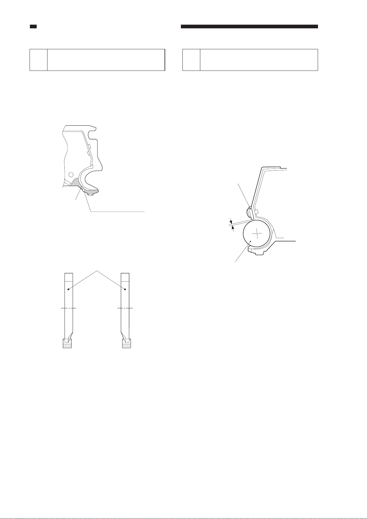
Mounting the Developing
3
Assembly Blade
The blade is adjusted to a high accuracy
when it is mounted to the blade mount. Avoid
detaching it from its mount.
• If you must replace the blade on its own,
be sure to adjust the position of the blade
so that the gap between the blade and the
developing cylinder is 0.21 ±0.03 mm
when measured with a gap gauge (CK-
0057-000).
Blade
0.21± 0.03mm
Magnetic seal
(rear) (front)
Figure 2-15
Developing cylinder
Figure 2-16
The surface of the developing cylinder
can easily be damaged. Be sure to slide the gap
gauge along its both ends.
2-10
Page 21
CHAPTER 2 STANDARDS AND ADJUSTMENTS
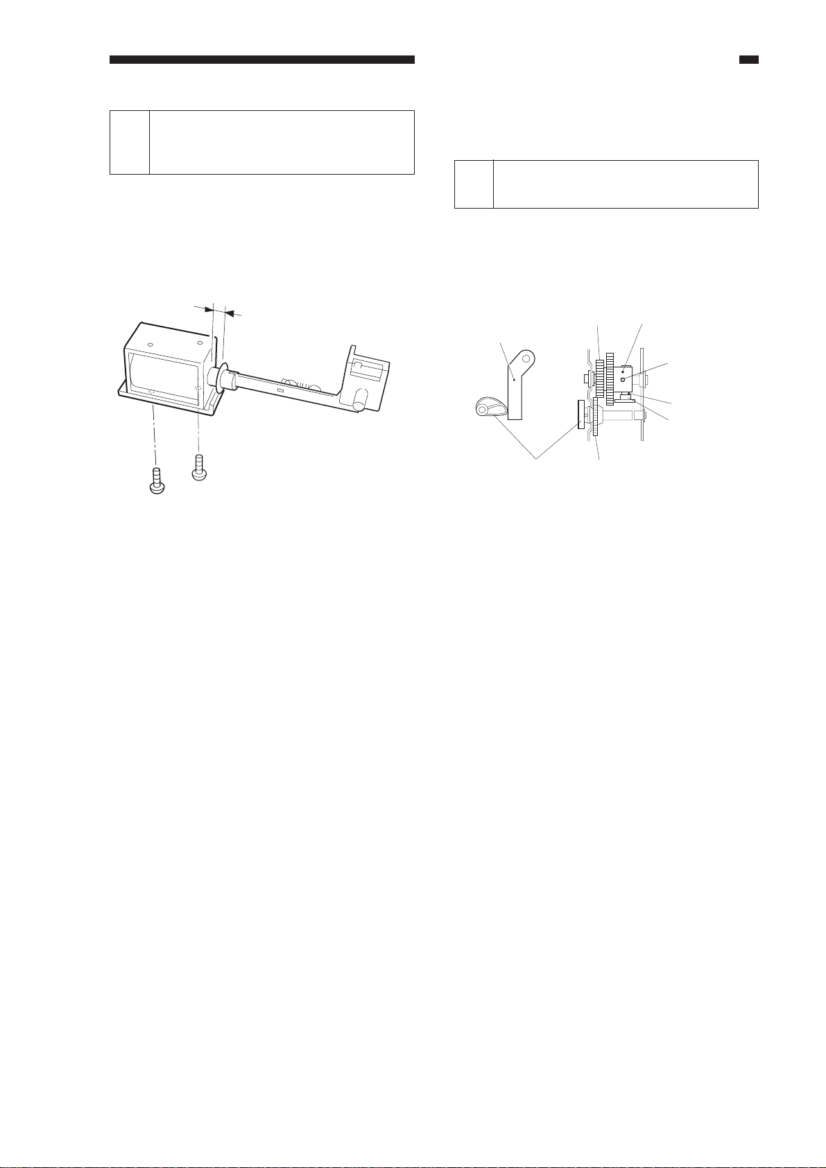
Adjusting the Positioning the
Primary Charging Roller Cleaning
4
Solenoid
Make adjustments so that the length of the
primary charging roller solenoid (SL1)
indicated in the figure is 4.0 ±0.2 mm.
4.0 ± 0.2mm
Figure 2-17
D. Pick-Up/Feeding System
Adjusting the Positioning the
1
Multifeeder paper Guide Cam
Make adjustments so that the paper guide
plate cam is as shown when the solenoid plate
is in contact with the claw of the control ring.
Control ring
Screw w/ hex hole
Claw
Solenoid plate
Paper guide plate
Paper guide plate
Gear 1
Gear 2
Figure 2-18
2-11
Page 22
CHAPTER 2 STANDARDS AND ADJUSTMENTS
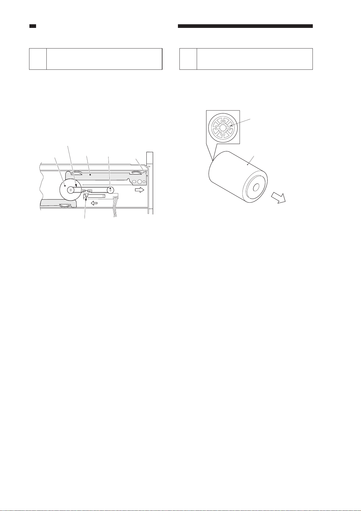
Attaching the Timing Belt in
2
the Multifeeder
1) Butt the side guide plate of the multifeeder
against the end (A; open condition).
2) Move the slide volume to the center
(direction B), and fit the timing belt on the
pulley.
Timing belt
Pulley
Rack plate
Slide volume
Pulley
A
Mounting the Multifeeder Pick-
3
Up Roller
Mount the multifeeder pick-up roller [1]
so that the side with a cross [2] on its collar is
toward the rear.
[2]
[1]
Figure 2-20
Figure 2-19
2-12
Page 23

Mounting the Delivery
Assembly Paper Deflecting
4
Plate Solenoid (SL2)
1) Remove the delivery assembly.
2) Place the delivery assembly upright on a
flat desk.
3) Push in the steel core of the paper
deflecting plate 1 solenoid (SL2) until it
stops.
4) Loosen the adjusting screw, and make
adjustments so that the gap between the
steel core E-ring of the solenoid and the
solenoid frame is about 0.2 mm.
5) Mount the delivery assembly.
CHAPTER 2 STANDARDS AND ADJUSTMENTS
Paper deflecting plate
1 solenoid (SL2)
Figure 2-21
0.2mm
2-13
Page 24

CHAPTER 2 STANDARDS AND ADJUSTMENTS
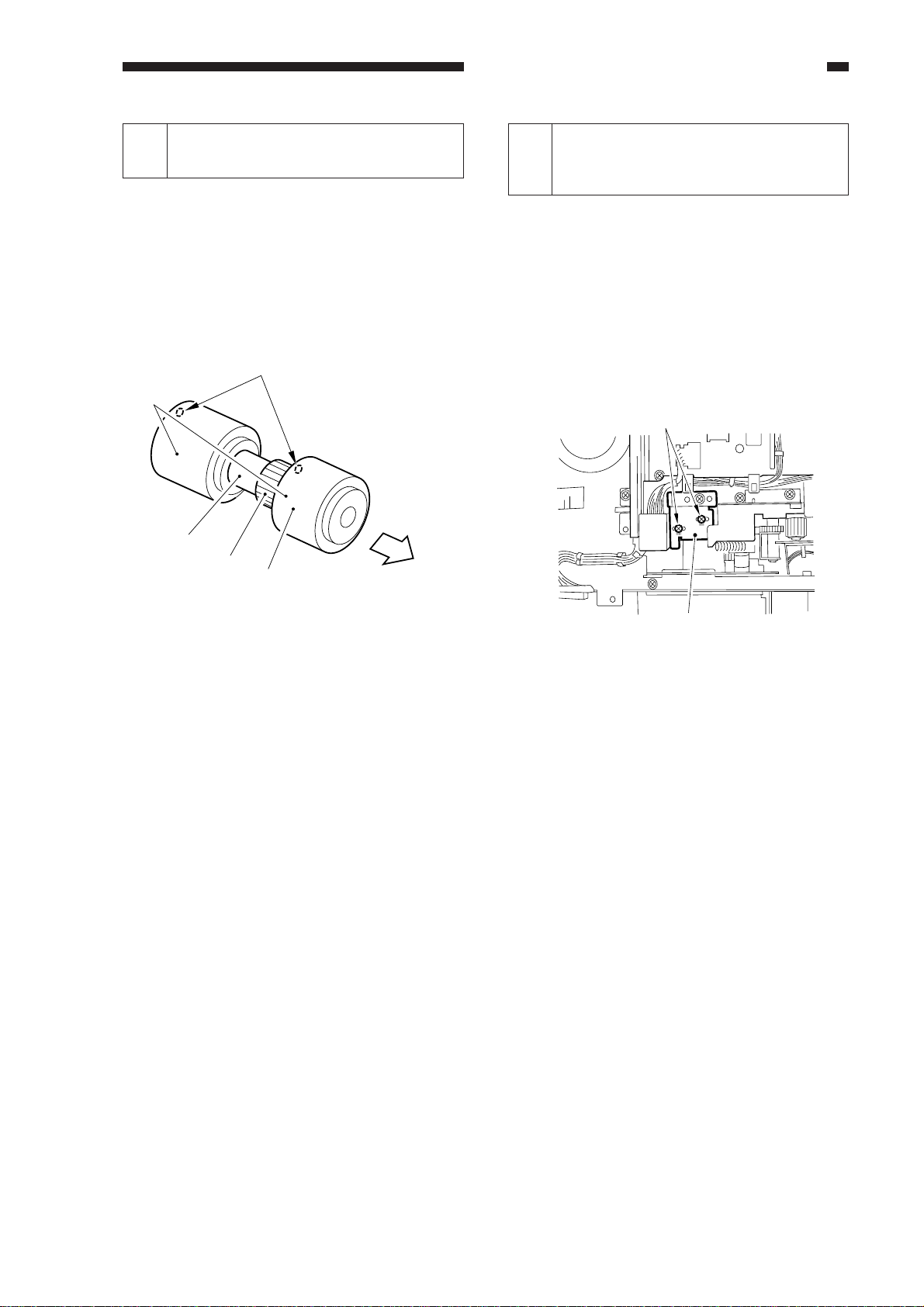
Orienting the Multifeeder Pick-Up Roller
5
(side paper deck)
Mount the multifeeder pick-up roller by reversing the steps used to remove it with the
following in mind:
• The pick-up roller used at the front and the one used at the rear are not interchangeable.
• The collar of the pick-up roller used at the front is silver in color.
When mounting the deck pick-up roller [1] for the front, orient it so that the marking [2] on the
collar (silver) is toward the front, and the marking [3] on the side of the roller is toward the rear.
[3]
(direction
of rotation)
[1]
Collar (silver)
[2]
(front)
Figure 2-22 Pick-Up Roller for the Front
• The collar of the pick-up roller used at the rear is gold in color.
When mounting the deck-pick-up roller [4] for the rear, orient it so that the marking [5] on the
side and the marking [6] on the collar (gold) are toward the rear.
[5]
(direction
of rotation)
[6]
2-14
[4]
Collar (gold)
(rear)
Figure 2-23 Pick-Up Roller for the Rear
Page 25
CHAPTER 2 STANDARDS AND ADJUSTMENTS
Orienting the Side Paper Deck
6
Feeding Roller
Mount the feeding roller [1] to the side
paper deck pick-up assembly so that the belt
pulley [2] is toward the front.
When attaching the pick-up/feeding roller
rubber to the pick-up/feeding roller shaft, be
sure that the marking [3] is toward the rear.
[5]
[3]
[4]
[2]
[1]
(front)
Positioning the Side Paper
Deck Pick-Up Roller Releasing
7
Solenoid
Take note of the position of the two fixing
screws of the deck pick-up roller releasing
solenoid with reference to the scale on the
support plate before removing the solenoid.
Or, mark the position of the solenoid on the
support plate with a scriber.
When mounting the solenoid on its own,
be sure to secure it back to its initial position.
[2]
Figure 2-24
[1]
Figure 2-25
2-15
Page 26
CHAPTER 2 STANDARDS AND ADJUSTMENTS
E. Fixing System
When Mounting the Fixing
1
Heater
1) Do not touch the heater surface.
2) Orient it so that the side with the longer
heater wire is toward the front.
3) Mount the main heater (700 W) to the
right and the sub heater (600 W) to the left
when viewing the fixing assembly from
the front.
4) Connect the right faston of the heater to
the main heater and the upper faston to the
sub heater when viewing it from the rear.
(The fastons are found at the rear.)
Sub heater
(Delivery side)
Main heater
(pick-up side)
Adjusting the Lower Fixing
3
Roller Pressure (nip)
If you have replaced the upper fixing
roller or the lower fixing roller, or if fixing
faults occur, make the following adjustments:
If you are taking measurements while the
fixing roller is cold, leave the machine alone
for 15 min after it ends its wait period and
make 20 copies before taking measurements:
<Taking Measurements>
1) Make an A4 solid black copy, and make a
copy of it. Set the output in the
multifeeder.
2) Select NIP-CHK in service mode
(FUNCTION>FIXING), and press the
OK key.
3) The paper will be picked up and is stopped
between the fixing rollers temporarily;
then, it will automatically be discharged in
about 20 sec.
4) Measure the width of the area where toner
is shiny (Figure 2-27).
Upper fixing roller
Figure 2-26
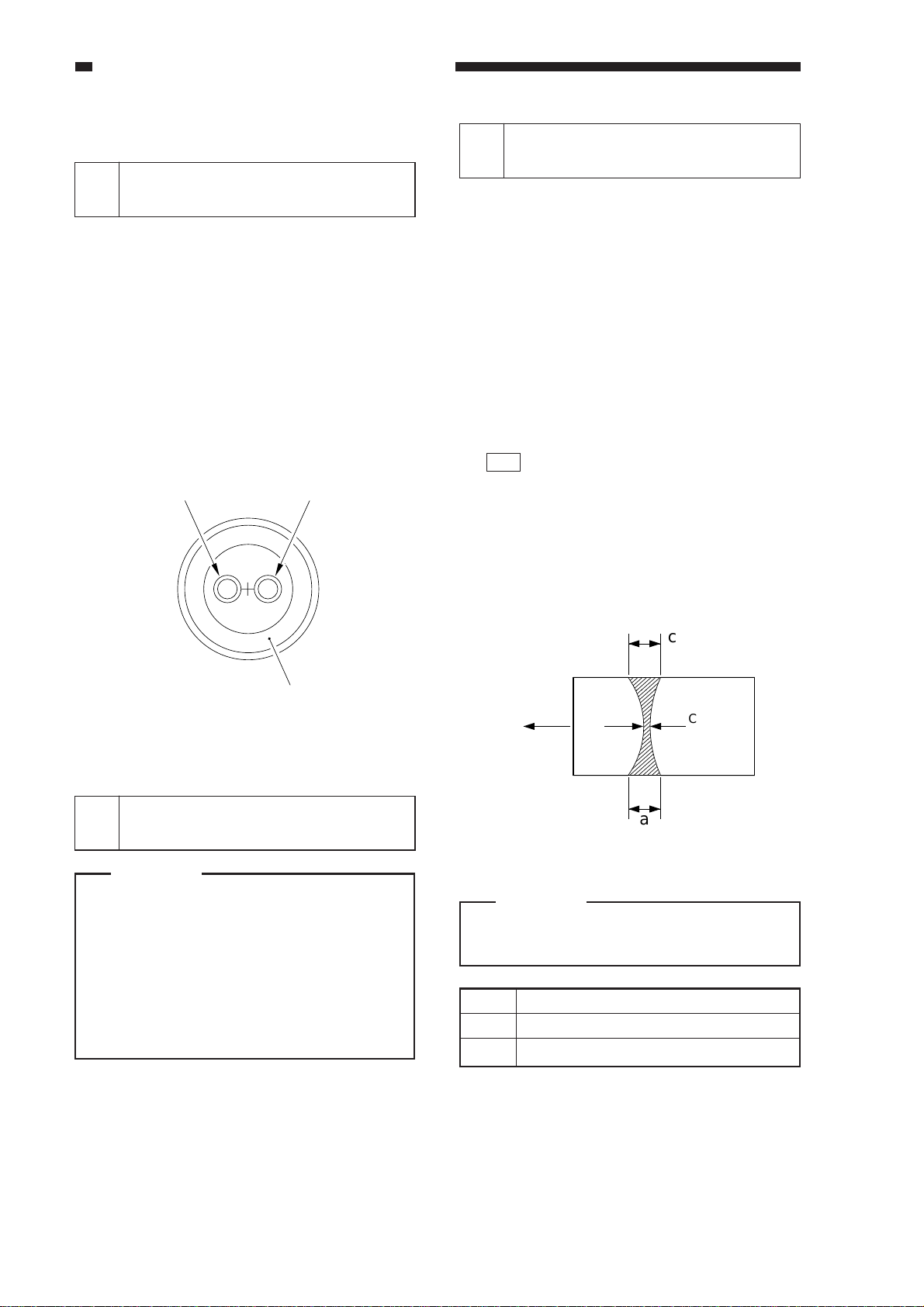
Positioning the Fixing
2
Assembly Paper Guide
Caution:
If you removed the inlet guide plate, you
would need to adjust the position of the
inlet guide. To avoid the work, do not
loosen the mounting screw (paintlocked) on the inlet guide mount;
otherwise, be sure to set it to its initial
position by referring to the scale on the
fixing assembly.
c
(Feeding
direction)
A3
b
Center of
the copy
a
Figure 2-27
Caution:
a and c are points 10 mm from both
edges of the copy paper.
Point
b
a-c
* Measured when the upper/lower roller is
adequately heated.
Measurements*
5.5 ±0.3 mm
0.5 mm or less
2-16
Table 2-1
Page 27

5) If not as indicated, turn the pressure
adjusting screw 1 found at the rear and the
front of the fixing assembly to make
adjustments.
[1]
Figure 2-28
When Replacing the Lower
4
Fixing Roller
CHAPTER 2 STANDARDS AND ADJUSTMENTS
When replacing the lower fixing roller or
the bearing of the lower roller shaft, be sure to
apply heat-resisting grease (MO-138S) to the
shaft to prevent adhesion of the shaft and the
bearing.
2-17
Page 28
CHAPTER 2 STANDARDS AND ADJUSTMENTS
F. Electrical System
1 Replacing the Major Part
Parts
Image processor
PCB
[A]
Composite power
supply PCB
Laser scanner
unit
Laser unit
CCD unit
Scanning lamp
DC controller
PCB
Standard white
plate
Control panel LCD
Multifeeder size
detecting volume
Fixing assembly
Fixing cleaning
belt
Description/Service mode
n Before Replacement
Generate stored data of ADJUST,
OPTION, and COUNTER.
n After Replacement
1) Execute RAM clear (image
processor PCB).
2) Enter data under AJDUST and
OPTION.
3) Execute shading auto correction 2.
4) Execute density correction.
4-1) Execute standard white plate
density read.
4-2) Execute density auto correction.
4-3) Execute DZ density auto
correction.
n After Replacement
1) Enter the values indicated on the
label attached to the composite
power supply PCB in service mode.
2) Execute shading auto correction 1.
3) Execute auto density correction.
1) Execute shading auto correction 1.
2) Execute auto density correction.
1) Execute shading auto correction 2.
2) Execute auto density correction.
Adjust the coordinate position of the
analog touch panel.
Store the paper width basic value for
the multifeeder.
Nip (as indicated?)
Execute cleaning belt clear.
FUNCTION>MISC-P>P-PRINT
FUNCTION>CLEAR>IP
YAKUNUKE
FUNCTION>CCD>MAN-ADJ
FUNCTION>DENS>WHITE-ME
FUNCTION>DENS>PD-DENS
FUNCTION>DENS>DZ-DENS
FUNCTION>DENS>DZ-ME
FUNCTION>CCD>CCD-ADJ
Same as [A] above.
FUNCTION>CCD>CCD>ADJ
Same as [A] above.
FUNCTION>CCD>MAN-ADJ
Same as {A] above.
FUNCTION>PANEL>TOUCHKEY
FUNCTION>CST>MF-A4R, A6R, A4
FUNCTION>FIXING>NIP-CHK
COUNTER>MISC>FIX-WEB
2-18
Page 29
CHAPTER 2 STANDARDS AND ADJUSTMENTS
2 Shading Auto Correction
• Shading auto correction may be either of two types (CCD-ADJ, MAN-AJD). Select the
appropriate mode.
• In shading auto correction, various data measurements are taken and stored in the RAM on the
image processor PCB for use as the target value for shading correction performed before
scanning operation.
The following are service mode item related to shading auto correction; see the appropriate
service mode item for details:
ADJUST
FUNCTION
ADJ-XY
CCD
CCD
ADJ-S
PPR
W-PLT
CCD-ADJ
MAN-ADJ
standard white plate read position
standard white paper density data
standard white plate density data
shading auto correction 1 (for normal image adjustment)
shading auto correction 2 (for PCB, lamp replacement)
n Using CCD-ADJ
• Start service mode.
1) Press the asterisk key.
2) Press '2' and '8' on the keypad at the same time.
3) Press the asterisk key.
4) On the screen, select <COPIER>, <FUNCTION>, and <CCD> in sequence.
5) Select <CCD-ADJ>, and press the OK key. (You need not place standard white paper.)
n Using MAN-ADJ
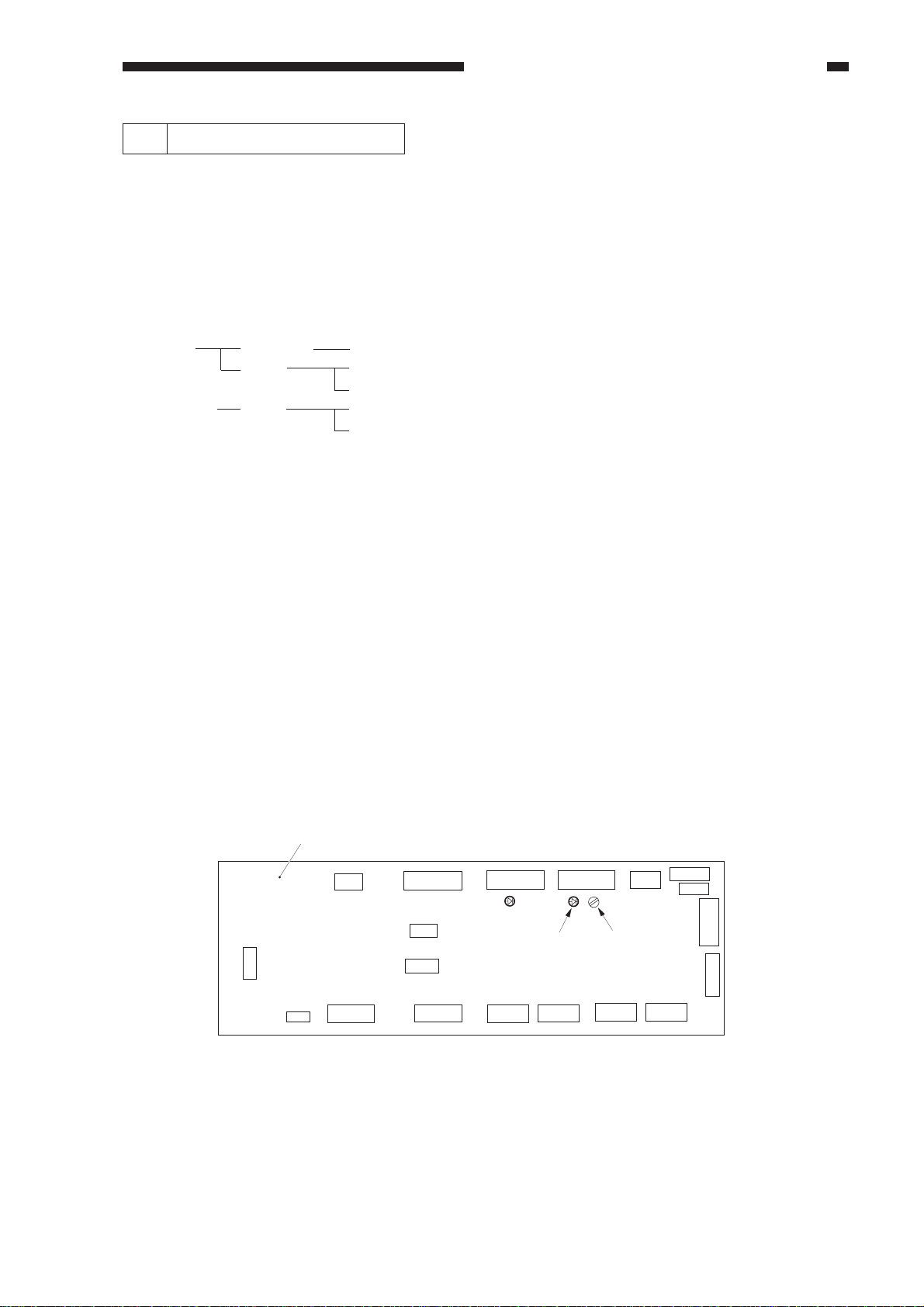
1) Remove the rear cover, and check the position of VR200 on the DC controller PCB.
2) Place the standard white paper on the copyboard glass.
3) Start service mode. (See steps 1) through 4) under "Using CCD-ADJ.")
4) Select <MAN-ADJ>, and press the OK key.
5) When VO is indicated and the beep is sounded, press the OK key. If the beep is not heard, turn
VR200 on the DC controller PCB; when the beep is sounded, press the OK key. Adjustments
are needed if LED201 turns on.
6) Check to see if END is indicated.
DC controller PCB
Figure 2-29
LED201
VR200
2-19
Page 30

CHAPTER 2 STANDARDS AND ADJUSTMENTS
3 Copy Density Auto Correction
n Execute copy density auto correction for the following:
The copy image is not proper (image fault).
The laser unit has been replaced.
The image processor has been replaced.
The composite power supply PCB has been replaced.
n When executing copy density auto correction, be sure to execute the following three types (five
items) as a set. Be sure to execute shading correction before executing density correction.
• Standard white paper density read FUNCTION>DENS>WHITE-ME
• PD density auto correction FUNCTION>DENS>PD-DENS
(text, text/photo mode) FUNCTION>DENS>PD-ME
• DZ density auto correction FUNCTION>DENS>DZ-DENS
(photo mode) FUNCTION>DENS>DZ-ME
n The following blocks are subjected to correction processing:
Laser characteristic correction
Developing bias correction
n Executing the Mode
a. Executing Shading Correction
1) Start service mode.
2) Select COPIER>FUNCTION>CCD in sequence; then, select <CCD-ADJ>.
3) Press the OK key. (You need not place standard white paper.)
4) End service mode; then, make two solid black copies while holding the feeder or the copyboard
glass open. Check to make sure that white lines did not occur.
2-20
Page 31

CHAPTER 2 STANDARDS AND ADJUSTMENTS
b. Executing WHITE-ME
1) Place five sheets of standard white paper, and close the feeder or the copyboard cover.
• Be sure that the paper is A4 or larger and placed vertically.
2) Start service mode, and select COPIER>FUNCTION-DNS>WHITE-ME.
3) Press the Copy Start key.
• The scanner moves forward and reads the white paper.
White paper
Figure 2-30
c. Executing PD-DENS
1) Select COPIER>FUNCTION>DENS>PD-DENS, and press the OK key.
• A 15-graduation patter will be generated. (The patches are black.)
d. Executing PD-ME
1) Remove the white paper from the copyboard, and place the PD-DENS output on the
copyboard.
• Place the printed side down (for reading the pattern).
• Place the white side as the leading edge and the black side toward the center.
• Be sure to place originals against the marking V on the copyboard glass.
In practice, place
it so that the printed
side is down.
PD-DENS output
Figure 2-31
2-21
Page 32

CHAPTER 2 STANDARDS AND ADJUSTMENTS
2) Select <PD-ME> under <PD-DENSE>; then, press the OK key.
• The scanner makes 13 scans.
3) After reading operation, PD auto density correction ends when OK is indicated to the right of
<PD-ME>. If NG, check the following:
• Is the original placed correctly?
• Is the original the PD-DENS output? (The patches are black.)
After checking the above, execute PD-DENS once again. If still NG, go to the next page.
d. Executing DZ-DENS
1) Select COPIER>FUNCTION>DENS>DZ-DENS; then, press the OK key.
• A 15-gradation pattern will be generated. (The patches are white.)
e. Executing DZ-ME
1) Remove the PD-DENS output (black patches), and place the DZ-DENS output (white patches)
on the copyboard glass.
In practice, place the
printed side down.
DZ-DENS output
Figure 2-32
2) Select <DZ-ME> under DZ-DENS, and press the OK key.
• The scanner makes 13 scans.
3) After read operation, PD auto density correction ends when OK is indicated to the right of
<DZ-ME>. If NG, check the following:
• Is the read original placed correctly?
• Is the read original the DZ-DESN output? (The patches are white.)
After checking the above, execute DZ-DENS once again. If still NG, go to the next page.
2-22
Page 33

CHAPTER 2 STANDARDS AND ADJUSTMENTS
n If PD-ME/DZ-ME Is NG
1. Clean the scanner.
2. Isolate the problem.
Execute toner stirring COPIER>FUNCTION>INSTALL>TONER-S
Execute drum resistance measurement COPIER>FUNCTION>DPC>D-GAMMA
A this time, take notes of the measurement of D-GAMMA.
3. Execute copy density correction once again.
If the result is still NG, perform the following according to the measurement of D-GAMMA.
If 2.3 or higher, replace the drum cartridge.
If 0.1 or lower, replace the developing assembly.
2-23
Page 34

CHAPTER 2 STANDARDS AND ADJUSTMENTS
4 Storing the Multifeeder Paper Width Basic Value
Execute this mode if you have replaced the multifeeder paper width detecting volume.
Be sure to try A4R, A6R, and A4 in the order indicated.
n Execution
1) Replace the paper width detecting VR.
2) Start service mode.
asterisk key -> '2' and '8' at the same time -> asterisk key
3) Select COPIER>FUNCTION>CST, and highlight <A4R>.
Display
< CST >
MF-A4R
MF-A6R
MF-A4
I/O
Adjust
Function
< 1/1 > < READY >
Option Test
+/-
OK
Counter
Figure 2-33
4) Place A4R paper in the multifeeder, and adjust the side guide to the paper width.
5) Press the OK key.
6) Repeat steps 3) through 5) for A6R and A4 as in A4R.
7) Press the Reset key to end service mode; then, turn off and then on the main power switch.
2-24
VR output ➞
A4
A4R
A6R
A6R
(105mm)
Paper width ➞
Figure 2-34
A4R
(210mm)A4(297mm)
Page 35

CHAPTER 2 STANDARDS AND ADJUSTMENTS
5 Checking the Photointerrupters
The photointerrupters may be checked in either of the following two methods:
a. Using a meter.
b. Using service mode (I/O mode).
a. Using a Meter
You cannot insert the meter probe directly into the connectors of the machine's PCBs, as they
are designed specially to enable smooth connection. Obtain a probe extension tool (FY9-3038-000/
FY9-3039-000).
1) Set the digital multimeter range to 12 VDC.
2) Connect the meter probe to GND (0 VDC) of the DC controller PCB.
3) Make a check as indicated. (Use the probe extension and the clip as necessary.)
[ Connection 1 ]
Pinch the pin.
FY9-2003-000
Meter
[ Connection 2 ]
Pinch the pin
Probe extension
(FY9-3038)
FY9-2004-000
Probe extension
Clip
7537
04
DIGITAL
MULTIMETER
YOKOGAWA
D•H
Å|
4
2
mV
0
2
Å{
REL/%
POWER
4
MIN/MAX
DATA-H
RANGE
AVG
SELECT
/Å`/Hz
mA
ÉA
10A
Å}
/
Åé
É∂
/Å`/ADP/KÅé
mV
+
Å`
/
LoHz/rpm
V
OPEN
Å`V
Hz
TERMINAL
SHUTTER
20
TRUE RMS
10
kHz
A
0.1% V
mA•ÉA
COM
FUSED
V•
FUSED
É∂
•
1000V
MAX
!
Meter
7537
04
DIGITAL
MULTIMETER
YOKOGAWA
D•H
Å|
4
2
mV
0
2
Å{
REL/%
POWER
4
MIN/MAX
DATA-H
RANGE
AVG
SELECT
/Å`/Hz
mA
ÉA
10A
Å}
/
Åé
É∂
/Å`/ADP/KÅé
mV
+
Å`
/
LoHz/rpm
V
OPEN
Å`V
Hz
TERMINAL
SHUTTER
20
TRUE RMS
10
kHz
A
0.1% V
mA•ÉA
COM
FUSED
V•
FUSED
É∂
•
1000V
MAX
!
Figure 2-35
b. Using Service Mode
1) Start service mode.
2) Press COPIER>I/O, and select DC-CON.
The bit number notations in the tables that follow represent the following:
ex.P001 00000000
bit7 bit0
2-25
Page 36

CHAPTER 2 STANDARDS AND ADJUSTMENTS
Notation
name
Meter probe
Service mode
Check (Normal if
described.)
Display reading
Meter reading (approx.)
Notation
name
Meter probe
Service mode
Check (Normal if
described.)
Display reading
Meter reading (approx.)
PS1
Scanner home position
sensor (PS1S)
J112-B5
While in standby, move
the scanner from the
home position.
When the
scanner is
at the
home
position,
-
5 V
Registration paper
sensor (PS4S)
While in standby, open
the right door, and
insert paper.
When
paper is
not
inserted,
1
5 V
When the
copyboard
cover is
closed,
1
0 V
PS4
J108-B11
P004-bit3
When
paper is
inserted,
0
0 V
PS2
Copyboard cover open/
closed sensor (PS2S)
J108-B2
P003-bit13
While in standby, open
and close the
copyboard cover.
When the
scanner is
not at the
home
position,
-
5 V
Internal delay sensor
(PS6S)
While in standby, open
the delivery assembly,
and move the flag of
PS6.
When the
flag is
blocking
the sensor
(paper
absent),
1
5 V
When the
cupboard
cover is
opened,
0
0 V
PS6
J106-2
P004-bit8
When the
flag is not
blocking
the sensor
(paper
present),
0
0 V
PS3
Multifeeder paper
sensor (PS3S)
J108-B17
P005-bit1
While in standby, place
paper on the
multifeeder tray.
When
paper is
placed,
1
5 V
External delivery
sensor (PS7S)
While in standby, open
the delivery assembly,
and move the flag of
PS7.
When the
flag is not
blocking
the sensor
(paper
present),
1
5 V
When
paper is
not
placed,
0
0 V
PS7
J107-2
P004-bit5
When the
flag is
blocking
the sensor
(paper
absent),
0
0 V
2-26
Page 37

CHAPTER 2 STANDARDS AND ADJUSTMENTS
Notation
name
Meter probe
Service mode
Check (Normal if
described.)
Display reading
Meter reading (approx.)
Notation
name
Meter probe
Service mode
Check (Normal if
described.)
PS8
Duplexing assembly
inlet paper sensor
(PS8S)
J114-B2
P004-bit5
While in standby, open
the delivery assembly,
and move the flag of
PS8.
When the
flag is
blocking
the sensor
(paper
absent),
1
5 V
Vertical path sensor
(PS11)
While in standby, move
up the lever of PS11.
When the
flag is not
blocking
the sensor
(paper
present),
0
0 V
PS11
J108-B8
P004-bit2
PS9
Re-pick up sensor
(PS9S)
J114-B5
P004-bit10
While in standby, open
the duplexing unit, and
move the flag of PS9.
When the
flag is
blocking
the sensor
(paper
absent),
1
5 V
Right cover open/
closed detecting sensor
(PS12S)
While in standby, open
the right door.
When the
flag is not
blocking
the sensor
(paper
present),
0
0 V
PS12
J108-B14
P003-bit13
PS10
Horizontal registration
paper sensor (PS10S)
J102-A8
P004-bit11
While in standby, open
the right door; then,
insert paper into the repick up assembly, and
slide it to the rear.
When the
paper is
slid to the
rear,
1
5 V
Left cover open/closed
sensor (PS13S)
While in standby, open
the left door.
When the
paper is
not slid to
the rear,
0
0 V
PS13
J114-5
P003-bit11
Display reading
Meter reading (approx.)
When the
lever is
moved up
(paper
present),
1
5 V
When the
lever is
moved
back
(paper
absent),
0
0 V
When the
right door
is closed,
1
5 V
When the
right door
is open,
0
0 V
When the
left door
is closed,
1
5 V
When the
left door
is open,
0
0 V
2-27
Page 38

CHAPTER 2 STANDARDS AND ADJUSTMENTS
Notation
name
Meter probe
Service mode
Check (Normal if
described.)
Display reading
Meter reading (approx.)
Notation
name
Meter probe
Service mode
Check (Normal if
described.)
PS14
Front cover open/
closed sensor (PS14S)
J102-A11
P003-bit4
While in standby, open
the front cover.
When the
front
cover is
open,
1
5 V
Fixing assembly outlet
sensor (PS40S)
While in standby, push
the lever on the fixing
assembly outlet
assembly.
When the
lever is
pushed,
When the
front
cover is
closed,
0
0 V
PS40
J114-A2
P004-bit9
When the
lever is
not
pushed,
PS18
Cassette 1 pick-up
sensor (PS18S)
J108-A17
P004-bit0
While in standby, slide
out the cassette, and
insert paper between
the pick-up rollers.
When
paper is
inserted,
1
5 V
When
paper is
not
inserted,
0
0 V
PS19
Cassette 1 pick-up
sensor (PS19S)
J108-A18
P004-bit1
While in standby, slide
out the cassette, and
insert paper between
pick-up rollers.
When
paper is
inserted,
1
5 V
When
paper is
not
inserted,
0
0 V
Display reading
Meter reading (approx.)
2-28
1
5 V
0
0 V
Page 39

CHAPTER 3 ARRANGEMENT AND FUNCTIONS OF ELECTRICAL PARTS
CHAPTER 3
ARRANGEMENT AND FUNCTIONS OF
ELECTRICAL PARTS
3
3-1
Page 40

CHAPTER 3 ARRANGEMENT AND FUNCTIONS OF ELECTRICAL PARTS
A. Clutches and Solenoids
SL2
SL6
SL4
CL4
SL1
CL2
SL3
CL1
CL3
SL5
3-2
Figure 3-1
Page 41

CHAPTER 3 ARRANGEMENT AND FUNCTIONS OF ELECTRICAL PARTS
Clutches and Solenoids
Symbol Part
Clutch
C L
Solenoid
S L
Notation
CL1
CL2
CL3
CL4
SL1
SL2
SL3
SL4
SL5
SL6
Function
Drives the registration roller.
Drives the multifeeder pick-up
mechanism.
Drives the vertical path roller.
Drives the developing cylinder.
Moves down the pick-up roller.
Drives the delivery flapper.
Releases the multifeeder holding
plate.
Cleans the primary charging roller.
Drives the fixing cleaning belt.
Drives the fixing assembly inlet
guide.
3-3
Page 42

CHAPTER 3 ARRANGEMENT AND FUNCTIONS OF ELECTRICAL PARTS
B. Motors
M3
M1
M8
M10
M6
M5
M9
M4
M2
M7
3-4
Figure 3-2
Page 43

Motor
CHAPTER 3 ARRANGEMENT AND FUNCTIONS OF ELECTRICAL PARTS
Symbol Part
Motor
M
Notation
M1
M2
M3
M4
M5
M6
M7
M8
M9
M10
Function
Main motor
Fixing motor
Scanner motor
Laser scanner motor
Pick-up motor
Lower feeder motor
Reversal delivery motor
Delivery motor
Horizontal registration sensor shift
motor
Duplexing reversal motor
3-5
Page 44

CHAPTER 3 ARRANGEMENT AND FUNCTIONS OF ELECTRICAL PARTS
FM10
FM11
FM8
FM7
FM17
FM18
C. Fan
FM13
FM12
FM3
FM4
FM9
FM2
FM1
FM5
FM16
FM15
FM14
FM6
Figure 3-3
3-6
Page 45

Fans
CHAPTER 3 ARRANGEMENT AND FUNCTIONS OF ELECTRICAL PARTS
Symbol Part
fan
* Rotates at half speed during standby.
Notation
FM1
FM2*
FM3*
FM4*
FM5*
FM6*
FM7*
FM8*
FM9
FM10
FM11
FM12*
FM13*
FM14
FM15
FM16
FM17*
FM18*
Function
Feeding fan
Fixing heat discharging fan 1
Fixing heat discharge fan 2
Laser drive cooling fan
Laser scanner motor cooling fan 1
Laser scanner motor cooling fan 2
Cleaner cooling fan
System cooling fan
Reversal guide cooling fan
Low-voltage power supply cooling
fan 1
Low-voltage power supply cooling
fan 2
Reader cooling fan 1
Leader cooling fan 2
Drum cartridge cooling fan 1
Drum cartridge cooling fan 2
Drum cartridge cooling fan 3
DC controller PCB cooling fan
Scanner motor cooling fan
3-7
Page 46

CHAPTER 3 ARRANGEMENT AND FUNCTIONS OF ELECTRICAL PARTS
D. Sensors
PS2
PS14
PS4
SD4
PS1
SD3
PS11
PS18
PS3
PS12
PS13
PS7
PS8
PS6
PS40
SD1
PS9
SD2
PS19
PS10
TS1
3-8
Figure 3-4
Page 47

Sensors
CHAPTER 3 ARRANGEMENT AND FUNCTIONS OF ELECTRICAL PARTS
Symbol Name
Photointerrupter
Piezoelectric
oscillating
element
Notation
PS1
PS2
PS3
PS4
PS6
PS7
PS8
PS9
PS10
PS11
PS12
PS13
PS14
PS18
PS19
PS40
TS1
Remarks
Scanner home position detection
Copyboard cover open/closed
detection
Multifeeder paper detection
Pre-registration paper detection
Internal delivery assembly paper
detection
External delivery assembly paper
detection
Re-pick up assembly paper detection
Re-pick up assembly paper detection
Horizontal registration paper
detection
Vertical path paper detection
Right door open/closed detection
Left door open/closed detection
Waste toner detection
Cassette 1 retry paper detection
Cassette 2 retry paper detection
Fixing assembly outlet paper
detection
Toner level detection
Reflecting type
sensor
SD1
SD2
SD3
SD4
Original size sensor 1
Original size sensor 2
Original size sensor 3
Original size sensor 4
3-9
Page 48

CHAPTER 3 ARRANGEMENT AND FUNCTIONS OF ELECTRICAL PARTS
E. Switches and Counters
SW1
SW3
SW2
FL1
TH2
TH1
RL1
SSR1
CB1
THSW1
H1
H2
VZ1
LCD1
CNT1
3-10
Figure 3-5
Page 49

CHAPTER 3 ARRANGEMENT AND FUNCTIONS OF ELECTRICAL PARTS
Switches, Counters, Heaters, Varistors, and Fuses
Part
Switch
Counter
Varistor
SSR
Scanning lamp (fluorescent
lamp)
Heater
Thermistor
Thermal switch
Circuit breaker
Notation
SW1
SW2
SW3
CNT1
VZ1
SSR1
FL1
H1
H2
TH1
TH2
THSW
CB1
Name
Main power supply switch
Front door switch
Cassette heater switch
Total copy counter 1
Pre-registration guide varistor
Solid state relay
Scanning lamp
Fixing main heater
Fixing sub heater
Fixing heater main thermistor
Fixing heater sub thermistor (end)
Fixing heater thermal switch
Circuit breaker
3-11
Page 50

CHAPTER 3 ARRANGEMENT AND FUNCTIONS OF ELECTRICAL PARTS
18
21
20
19
22
17
16
F. PCBs
12
8
9
10
11
15
3
4
5
6
2
7
23
13
14
1
3-12
Figure 3-6
Page 51

CHAPTER 3 ARRANGEMENT AND FUNCTIONS OF ELECTRICAL PARTS
Switches, Counters, Heaters, Varistors, and Fuses
Part
1
2
3
4
5
6
7
8
9
10
11
12
13
14
15
16
17
18
19
20
21
22
23
Notation
Composite power supply PCB
DC controller PCB
Image processor PCB
Accessories power supply
Pick-up unit PCB
Low-voltage power supply PCB
Noise filter
Control panel key PCB
Control panel CPU PCB
Inverter PCB
Downloading PCB
Function key PCB
Upper cassette size detection PCB
Lower cassette size detection PCB
Multifeeder paper width detection
PCB
Laser driver PCB
Laser scanner driver PCB
Analog processor PCB
BD PCB
Pre-exposure lamp PCB
Environment sensor PCB
Intensity sensor PCB
Battery PCB (accessory)
Name
HVT, lamp regulator, DC power
supply
DC load control (DC driver)
Image processing (main controller)
DADF, side paper deck
Pick-up assembly sensor
DC power supply
AC power supply noise removal
LCD (back light) power supply
Upper cassette size detection
Lower cassette size detection
Multifeeder paper width detection
Laser dive
Laser scanner motor drive
CCD drive, analog image processing
Laser beam detection
Photosensitive drum residual charge
removal
Machine internal humidity detection
Scanning lamp intensity detection
Fax image memory retention
3-13
Page 52

CHAPTER 3 ARRANGEMENT AND FUNCTIONS OF ELECTRICAL PARTS
G. Side Paper Deck
1. Sensors and Switches
PS104
PS102
PS109
SW102
PS107
SW101
PS108
PS106
PS105
SW100
PS103
PS101
3-14
Figure 3-7a (side paper deck)
Page 53

CHAPTER 3 ARRANGEMENT AND FUNCTIONS OF ELECTRICAL PARTS
Symbol Part
Photointerrupter
Switch
Microswitch
Table 3-1a (side paper deck)
Notation
PS102
PS103
PS104
PS105
PS106
PS107
PS108
PS110
SW100
SW102
SW103
Function
Deck lifter upper limit detection
Deck paper supply position detection
Deck set detection
Deck pick-up guide open detection
Deck vertical path paper detection
Deck pick-up paper detection
Deck paper detection
Deck lifter position detection
Deck open switch
Deck open detecting switch
Deck lifter upper limit detecting
switch
3-15
Page 54

CHAPTER 3 ARRANGEMENT AND FUNCTIONS OF ELECTRICAL PARTS
2. Motors, Solenoids, and PCBs
SL101
CL101
CL102
SL102
M102
[1]
M101
[2]
3-16
Figure 3-7b (paper deck)
Page 55

CHAPTER 3 ARRANGEMENT AND FUNCTIONS OF ELECTRICAL PARTS
Symbol Part
Motor
M
Clutch
C L
Solenoid
S L
PCB
Table 3-1b (paper deck)
Notation
M101
M102
CL101
CL102
SL101
SL102
[1]
[2]
Function
Deck main motor
Deck lifter motor
Deck vertical path clutch
Deck pick-up clutch
Deck pick-up roller releasing
solenoid
Deck open solenoid
Side deck driver PCB
Open switch PCB
3-17
Page 56

CHAPTER 3 ARRANGEMENT AND FUNCTIONS OF ELECTRICAL PARTS
H. Variable Resisters, Light-
Emitting Diodes, and
Check Pins by PCB
Of the variable resistors (VR), lightemitting diodes (LED), and check pins used in
the machine, those needed in the field are
discussed.
Caution:
1. Some LEDs emit dim light when they
are off because of leakage current.
This is a normal condition, and must
be kept in mind.
2. VRs that may be used in the field.
:
VRs that must not be used in the field.
:
Caution:
Those VRs and check pins not listed
in the tables are for factory use only,
requiring special tools and high
accuracy. Do not touch them in the
field.
3-18
Page 57

CHAPTER 3 ARRANGEMENT AND FUNCTIONS OF ELECTRICAL PARTS
1. Image Processor PCBs (main controller)
J715 J716
J714
J713
J723
J724
J712
J722 J721
SW702
2
1
OFF
3
ON
J720
J717
J702
J703
J701
J704
J705
J706
SW701
J711
J710
J709
J718
J707
J708
Figure 3-8
J721: Flash ROM slot for the IP-CPU (IP, DIMM); use the bottom slot for a 4-MB DIMM,
and the top slot for a 1-MB DIMM.
J722: Flash ROM slot for the DC-CPU (DCC DIMM); 1-MB, DIMM
K723, J724: Slot for expansion memory (32 MB each); however, be sure to use J723 first (as when
installing only one DIMM).
J720: Not used.
3-19
Page 58

CHAPTER 3 ARRANGEMENT AND FUNCTIONS OF ELECTRICAL PARTS
n SW701 States
SW1
SW2
SW3
SW4
SW5
SW6
AB
OFF
OFF
OFF
OFF
OFF
OFF
Inch
ON
OFF
ON
OFF
ON
OFF
AB/Inch
ON
ON
OFF
ON
OFF
OFF
A
OFF
ON
ON
ON
OFF
ON
n Size Configuration
Use service mode to set the appropriate size (COPIER>OPTION>BODY>MODEL-SZ).
MODEL-SZ setting
AB
Inch
A
AB/Inch
0
1
2
3
The setting will affect the following items:
• Pattern for default enlargement/reduction.
• Size detection by the feeder. (If the setting under FEEDER>OPTION>SIZE-SW in service
mode is '1', AB/Inch detection will be made regardless of the country of installation.
n Arrangement of the Original Sensor
The arrangement of original sensors may be changed. If the feeder is used, these switch settings
need not be changed, since detection will be by the feeder. For sensor arrangement, see
"Identifying the Size of Originals" in Chapter 3.
Use SW5 and SW6.
AB
Inch
A
AB
OFF
ON
OFF
Inch
OFF
OFF
ON
3-20
Page 59

CHAPTER 3 ARRANGEMENT AND FUNCTIONS OF ELECTRICAL PARTS
2. DC Controller PCB (DC driver)
J101
J114
J113 J112
J111
J110
J109
LED201
J116
J118
J115
J117
J119
J102
LED200
J103J104
VR200
J105
J106
J108
J107
Figure 3-9
LED200: Check it to find out the state of the composite power supply PCB is indicated by
flashing at different intervals. For details, see Table 13-601.
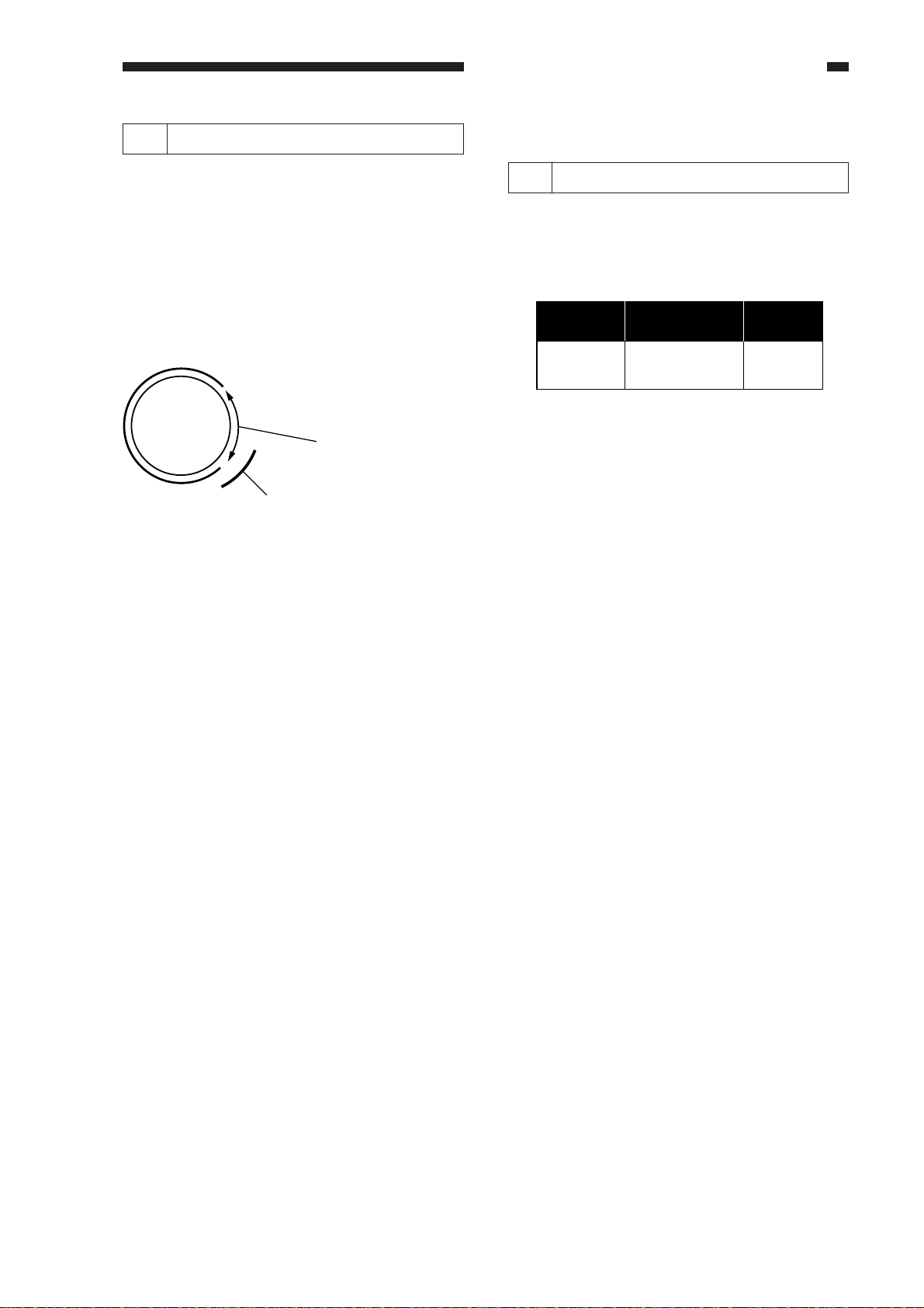
VR200: Turn it to adjust the lamp intensity used when shading auto correction
(FUNCTION>CCD>MAN-ADJ) is executed in service mode. The result is good if
LED201 turns on. Its adjustment range is equal to 3 rotations.
If LED201 does not turn on after a single rotation, try rotating it in the opposite
direction.
LED201: Check it to find out whether VR200 is correctly adjusted (it should turn on).
3-21
Page 60

CHAPTER 3 ARRANGEMENT AND FUNCTIONS OF ELECTRICAL PARTS
States and LED Flashing Intervals
Flashing intervals
u Flashes at 0.5-sec intervals
0.5 sec
ON
OFF
0.5 sec
u OFF for 4 sec; then, flashes twice
at 0.5-sec intervals
0.5 sec
ON
OFF
4 sec
Twice
u OFF for 4 sec; then, flashes 5 times
at 0.5-sec intervals.
0.5 sec
ON
OFF
4 sec
3 times
u OFF for 4 sec; then, flashes 3times
at 0.5-sec intervals.
0.5 sec
ON
OFF
4 sec
5 times
u OFF for 4 sec; then, flashes 4 times
at 0.5-sec intervals.
0.5 sec
ON
OFF
4 sec
4 times
u OFF for 4 sec; then, flashes 6 times
at 0.5-sec intervals.
0.5 sec
ON
OFF
4 sec
6 times
State
Normal
Over-current/over-
voltage detected
Error in
communication
with the DC
controller PCB
Low-voltage
control error* in
standby
Low-voltage
control error*
during copying
DC controller PCB
check sum
Error detection
Description
The composite power supply PCB is
operating normally.
An over-current/over-voltage condition
has been detected in the +24-VU or
+24-VR output.
An over-current condition has been
detected because of wire trapping or the
like.
n The control panel indicates 'E803'.
An error has occurred in
communication between the DC
controller PCB and the composite
power supply PCB, not updating the
communication data for 8 sec or more.
Note that this error may not flash/turn
on LED100 on the DC controller PCB.
• The output of the main transformer
stops.
• The control panel indicates 'E191'.
In standby, the difference between the
+24-VR setting and the actual control
value is larger than indicated.
• The output of the main transformer
stops.
• Error data is sent to the DC
controller PCB.
• The control panel indicates 'E803'.
During copying, the difference between
the +24-VR setting and the actual
control value is larger than indicated.
• +24 VR is set to standby voltage
(+18 VR).
• Error data is sent to the DC
controller PCB.
• The control panel indicates 'E803'.
The CPU on the DC controller PCB has
detected a check sum of communication
data twice or more continuously.
• The output of the main transformer
stops.
• The control panel indicates 'E191'.
* The same error can occur owing to activation error in the fluorescent lamp (because of deterioration
over time). If the LED flashes in threes or fours, check to see if the glass around the filament on
both sides of the lamp is not black.
3-22
Page 61

CHAPTER 3 ARRANGEMENT AND FUNCTIONS OF ELECTRICAL PARTS
3. Composite Power Supply CPB
J204
J206
J208
J220
J205
J209
J203
J201
J210
Figure 3-10
Label: Enter the values indicated on the label in service mode when replacing the composite
power supply CPB.
OFST-DC
AGS-GAIN
AGS-OFST
OFST1-AC
FL-OFST
xx
xxx
xxx
xxx
xxx
Table 3-2 Label on the Composite Power Supply PCB
3-23
Page 62

CHAPTER 3 ARRANGEMENT AND FUNCTIONS OF ELECTRICAL PARTS
4. Deck Driver (side paper deck)
13 6
J103
1
J104
12
1
J107
10
11
J105
2
J106
Figure 3-11
1
3
J101
1
7
J102
1
8
J108
1
3
J109
1
3-24
Page 63

CHAPTER 3 ARRANGEMENT AND FUNCTIONS OF ELECTRICAL PARTS
I. Upgrading
The machine may be upgraded in either of the following two ways:
• By replacing the DIMM on the image processor PCB.
• By updating the DIMM contents through downloading from a computer.
1. Replacing the DIMM
The DIMM (flash ROM) used in the machine comes in two types; both types are mounted on
the image processor PCB. Figure 3-12 shows a view in which the IP small cover has been removed:
• DIMM for the IP-CPU
4 MB: bottom of 2-layer slot
1 MB: top of 2-layer slot
• DC-CPU DIMM (1 MB)
DIMMs lot for
Image
processor PCB
DC-CPU
IP cover
Figure 3-12
DIMM slot for
IP-CPU
3-25
Page 64

CHAPTER 3 ARRANGEMENT AND FUNCTIONS OF ELECTRICAL PARTS
1. Removing the DIMM
1) Turn off the main power switch, and
disconnect the power cord.
2) Remove the copyboard glass; then,
remove the screw, and detach the small
cover from the IP cover.
Small cover
M4 × 4bis
3) Open the slot claw, and pull off the
DIMM as if to lift it.
IP,DIMM(1MByte)
Push
Push
Figure 3-13
Figure 3-14
3-26
Page 65

CHAPTER 3 ARRANGEMENT AND FUNCTIONS OF ELECTRICAL PARTS
2. Mounting the DIMM
1) Check the DIMM slot on the IP PCB. The
wrong slot can cause malfunction; pay
attention. (Figure 3-12)
2) Insert the DIMM into the slot at an angle.
At this time, check to be sure that the
DIMM is fully inserted into the slot.
3) Shift down the DIMM until the claw of
the slot clicks into position.
At this time, do not force in the DIMM;
such can damage the DIMM.
IP, DIMM (1 MB)
Cut-off
4) Mount the IP small cover (M4x4 screw, 1
pc.); then, mount the copyboard cover.
Connect the power cord, and turn on the
main power supply.
Figure 3-15
3-27
Page 66

CHAPTER 3 ARRANGEMENT AND FUNCTIONS OF ELECTRICAL PARTS
3. Downloading
1. Before Starting the Work
Obtain the following:
• PC to which the downloading tool
(service tool) has been installed.
• Bi-Centronics cable (with an IEEE 1284
Standard-compliant marking)
2. Downloading
a. Connection
• Check to make sure that the
communication memory lamp is off.
1) Turn off the machine's main power
switch; then, disconnect the power plug,
and disconnect the modular cable
(telephone).
2) Open the front door, and open the
connector cover for downloading.
3) Connect the machine to the PC with a biCentronics cable.
• Make sure that the PC is off.
• Connect the 25-pin connector of the cable
to the PC, and 36-pin connector to the
machine.
4) Slide the switch to LOAD.
Downloading switch
COPY
LOAD
Bi-Centronics interface
connector
Figure 3-17
5) Turn on the PC, and start the downloading
tool.
Connector cover
for downloading
Figure 3-16
Downloading
switch
COPY LOAD
Connector cover
opened
3-28
Page 67

CHAPTER 3 ARRANGEMENT AND FUNCTIONS OF ELECTRICAL PARTS
6) Connect the machine's power plug to the
power outlet, and turn on the main power
switch.
b. Downloading
1) Select 'To Main Menu' in response to the
start-up message of the downloading tool.
End
To Main Menu
2) Select 'Next' under the Download/Upload.
Manage Data
Next
Download/Upload
Next
3)
Click the model and PCB for downloading.
IP: DIMM for the IP-CPU
DC-CON: DIMM for the DC-CPU
4) Start upgrading the flash ROM following
the instructions on the PC screen.
5) When downloading is done, operate as
follows to turn off the PC:
OK → To Main Menu → End Tool →
End
To Main Menu
End
End Tool
3-29
Page 68

CHAPTER 3 ARRANGEMENT AND FUNCTIONS OF ELECTRICAL PARTS
c. After Downloading
1) Turn off the machine's main power
switch, and disconnect the power plug.
2) Disconnect the bi-Centronics cable from
the PC and the machine.
3) Slide the download switch to COPY.
Downloading switch
COPY
LOAD
Figure 3-18
4) Close the connector cover, and close the
front door.
5) If the machine is equipped with fax
functions, connect the modular cable.
6) Turn on the main power switch.
7) Start service mode, and check the ROM
version.
COPIER> DISPLAY>VERSION
3-30
Page 69

CHAPTER 4 SERVICE MODE
A. Outline
The machine's service mode is divided into the following seven:
CHAPTER 4 SERVICE MODE
Cause
1
2
3
4
5
6
7
Step
DISPLAY
I/O DISPLAY
ADJUST
FUNCTION
OPTION
TEST
COUNTER
Display Mode
I/O Display Mode
Adjustment Mode
Function Mode
Setting Mode
PG Test Mode
Counter Mode
Check
Table 4-1
1. Starting Service Mode and Making Selections
1) Press the asterisk key '
Display
Adjust
Function
OptionTest
Counter
I/O
<1/1> <READY>
<LAMP>
<(yyyyy) {aaaaa~ bbbbb}
xxxxx
FL-OFST
A press on
xxxxx: value before change
an item highlights
yyyyy: input value
the notation.
aaaaa-bbbbb: value input range
FL-OFST
' on the control panel.
+/-
OK
2) Press '2' and '8' on the keypad at the same time.
3) Press the asterisk key '
' on the control panel.
• The display changes to the screen shown in Figure 13-801, indicating the connected
accessories (FEEDER, SORTER, FAX).
4
COPIER
FEEDER
SORTER
FAX
COPIER Copier service mode
FEEDER DADF service mode
SORTER Finisher service mode
FAX Fax service mode
Figure 4-1
4-1
Page 70

CHAPTER 4 SERVICE MODE
2. Ending Service Mode
Press the Reset key once to return to the Service Mode Initial screen (Figure 4-1).
Press the Reset key twice to end service mode and return to the User screen (standard).
3. Backing Up the RAM
The RAM data may be backed up in either of the following two ways:
Service Label: The label is found on the left side of the back of the front cover (Figure 4-2).
Each machine is adjusted at the factory, and the adjustment values are recorded
in the label.
List Print: The command generates a back-up output of ADJUST, OPTION, and
COUNTER.
COPIER>FUNCTION>MISC-P>P-PRINT
• When Replacing the Image Processor PCB
Enter the values indicated in the list print obtained before replacement.
• When Replacing the Composite Power Supply PCB
Enter the values indicated on the label attached to the composite power supply.
4-2
Page 71

CHAPTER 4 SERVICE MODE
COPIER/ADJUST
Service Date
LAPM FL-OFST
FL-DUTY
FL-PDUTY
AE AE-TBL
ADJ-XY ADJ-X
ADJ-Y
ADJ-S
CCD PPR
W-PLT
LASER
DEVELOP DE-DC
DENS
HV-PRI P-DC
Boby No.
PVE-OFST
LA-OFF
DE-NO-DC
DE-OFST
DENS-ADJ
P-NO-DC
P-AC
P-NO-AC
Factory
1
Date.
COPIER/ADJUST
2
Service Date
HV-PRI
HV-TR TR-N1
FEED-ADJ REGIST
CST-ADJ MF-A4R
AGS-GAIN
AGS-OFST
OFST1-DC
OFST1-AC
OFST2-AC
P-AC2
P-AC3
TR-N2
TR-OFST
TR-SPP
LOOP-CST
LOOP-MF
ADJ-REFE
RVS-FD1
RVS-FD2
RVS-DUP
MF-A6R
MF-A4
Factory
FB4-3277
1 2
Figure 4-2 Service Label
OFST-DC
AGS-GAIN
AGS-OFST
OFST1-AC
FL-OFST
xx
xxx
xxx
xxx
xxx
Figure 4-3 Label on the Composite Power Supply PCB
4-3
Page 72

CHAPTER 4 SERVICE MODE
4. Basic Operation
The screen design consists of three layers: Level 1, Level 2, and Level 3 screens.
a. Initial Screen
COPIER
FEEDER
SORTER
FAX
Initial items
However, FEEDER, SORTER,
and FAX appear only when they are
installed.
Figure 4-4
• An initial item is selected when the highlighted notation is pressed.
b. Level 1/Level 2 Screen
Display
VERSION
USER
ACC-STS
ANALOG
CST-STS
JAM
ERR ALARM-1
HV-STS
I/O
Adjust
Function
Option Test
Level 1 item
Level 2 item
Counter
Figure 4-5
• To select a Level 1 item, press an item at the top of the screen.
• To select a Level 2 item, press a highlighted item.
4-4
Page 73

c. Level 3 Screen
FL-OFST
FL-OFST
<LAMP>
<1/1> <READY>
xxxxx
< (yyyyy) {aaaaa ~ bbbbb}
A press on
an item highlights
the notation.
xxxxx: value before change
yyyyy: input value
aaaaa-bbbbb: value input range
+/-
OK
Display
Adjust
Function
Option Test
Counter
I/O
Level 1 items
Level 2 item
CHAPTER 4 SERVICE MODE
Number of pages
; e.g., 1/3
Display
DC-CON
IP
PANEL
ANAPRO
POWER
I/O
<VERSION>
To previous page
Adjust
Function
< 1/3 > < READY >
Status
READY
JAM Paper jam
SERVICE Service operation
WAITING Initial rotation, etc.
DOORDoor open
COPYING Copying
ERROR Service error
Reverse + and -
To next page
Figure 4-6
Option Test
Ready for servicing/copying
+/-
Counter
OK
To store
Figure 4-7
• A level 3 item may be selected by pressing it, and the selection is indicated by highlighting
the item.
4-5
Page 74

CHAPTER 4 SERVICE MODE
d. Selecting a Screen
User screen
( )(2,8)( )
Level 1/2 screen
Reset key
Initial screen
Select an item
Select a Level 1 item at the top;
then, select a Level 2 item.
Level 3 screen Level 3 screen
To previous
/next screen
Reset key
From Level
1/2 screen
To previous
/next screen
Level 3 screen
Level 3 screen
To previous
/next screen
e. Guide to Keys
1. Keypad
Use it to enter a numeral (0 through 9).
2. User Mode Key
Use it to start user mode.
3. Reset Key
Use it to end service mode.
4. Stop Key
Use it to stop ongoing operation.
5. Clear Key
Use it to initialize settings in service mode or software counter readings.
6. Copy Start Key
Use it to make copies without ending service mode after making adjustments.
7. Previous Page Key
Use it to return to the previous page.
8. Next Page Key
Use it to move to the next page.
9. +/- Key
USe it to switch between + and -.
10. OK Key
Use it to store an input value.
Figure 4-8
4-6
Page 75

B. DISPLAY Control Display Mode
Figure 4-9 shows the DISPLAY mode Level 2 screen and its items.
CHAPTER 4 SERVICE MODE
Display
VERSION
USER
ACC-STS
ANALOG
CST-STS
JAM
ERR
HV-STS
I/O
Adjust
ALARM-1
Function
Option Test
Figure 4-9 DISPLAY Level 2 Screen
Counter
4-7
Page 76

CHAPTER 4 SERVICE MODE
Level 1
DISPLAY
Level 2
VERSION
USER
ACC-STS
ANALOG
CST-STS
JAM
ERR
HV-STS
ALARM1
Level 3
DC-CON
IP
PANEL
POWER
FEEDER
SORTER
PS-PCL
LIPS
SCSI
SDL-STCH
LANGUAGE
COUNTER
FEEDER
SORTER
DECK
CARD
PCB
RAM
TEMP
HUM
ABS-HUM
DR-TEMP
FIX-C
WIDTH-C1
WIDTH-C2
WIDTH-C3
WIDTH-C4
WIDTH-C5
WIDTH-C6
WIDTH-MF
WIDTH-DK
PRIMARY
BIAS
TR-V
DF
SORTER
DISPLAY Items
Outline
Indicates the DIMM version of the DC controller PCB.
Indicates the DIMM version of the image processor PCB.
Indicates the ROM version of the control panel controller PCB.
Indicates the ROM version of the composite power supply PCB.
Indicates the ROM version of the feeder controller PCB.
Indicates the ROM version of the sorter controller PCB.
Indicates the version of the ROM of the PS-PCL board.
Indicates the ROM version of the LIPS board.
Indicates the version of the ROM on the SCSI Board.
Indicates the version of the ROM of the saddle.
Indicates the ROM version of the LIPS board.
Indicates the selected language.
Indicates the counter control type for the copy counter.
Indicates the connection of a feeder.
Indicates the connection of the sorter.
Indicates the connection of the paper deck.
Indicates the connection of the control card.
Indicates the connection of various boards (accessories*).
Indicates the total size of the RAM recognized by the machine.
Indicates the machine internal temperature (environment sensor).
Indicates the machine internal humidity (environment sensor).
Indicates the absolute humidity.
Indicates the drum ambient temperature (drum ambient
temperature sensor).
Indicates the temperature of the upper fixing roller (main
thermistor).
Indicates the width of the paper in the cassette 1 and the output of
the paper size sensor.
Indicates the width of the paper in the cassette 2 and the output of
the paper size sensor.
Indicates the width of the paper in the cassette 3 and the output of
the paper size sensor.
Indicates the width of the paper in the cassette 4 and the output of
the paper size sensor.
Indicates the width of the paper in the cassette 5 and the output of
the paper size sensor.
Indicates the width of the paper in the cassette 6 and the output of
the paper size sensor.
Indicates the width of paper in the multifeeder and the output of
the paper size sensor.
Indicates the width of paper in the deck and the output of the
paper size sensor.
Indicates the jam history.
Indicates the error history.
Indicates the current value (A) of the primary charging roller.
Indicates the developing bias DC value (V).
Indicates the ATVAC value.
Indicates the most recent alarm of the feeder.
Indicates the most recent alarm of the sorter.
* Varies depending on the country.
4-8
Page 77

CHAPTER 4 SERVICE MODE
<VERSION> DISPLAY
Indicates the ROM version of the machine and the accessories PCBs.
Level 3
DC-CON
IP
PANEL
POWER
FEEDER
SORTER
SDL-STCH
LIPS
DIMM version f the DC controller PCB
DIMM version of the image processor PCB
ROM version of the control panel controller
PCB
ROM version of the composite power supply
PCB
ROM version of the feeder controller PCB
ROM version of the sorter controller PCB
ROM version of the saddle stitcher controller
PCB
ROM version of the LIPS board
Description
<USR>
Indicates the items related to the User screen and the user.
Level 3
LANGUAGE
COUTER
Notation: <LANGUAGE AA.BB.CC.DD>
Indicates the selected language.
AA: country code (not used in the machine)
BB: language code
CC: site code (See Table 14-803-1.)
DD: Paper configuration code (Table 14-802)
Notation: <COUNTER EE>
Indicates the type of copy counter count control.
EE: Counter code detail (Table 13-803)
Remarks
Notation: xx, yy
xx: version number
yy: R&D control number
RemarksDescription
Paper Configuration Code: DD
Code
00
01
02
03
Configuration
AB
Inch
A
AB/Inch
Table 4-2
Site Code: CC
Code
00
01
Model
Common model
Canon model
Table 4-3-1
Type Code: EE
Code
00
01
10
11
Total
Total
Copy total
All sizes
Counter 1
Counter 2
Pint total
Table 4-3
Counter 3
Fax print
Fax print
4-9
Page 78

CHAPTER 4 SERVICE MODE
<ACC-STS> DISPLAY
Indicates accessory connection.
Level 3
FEEDER
SORTER
DECK
CARD
PCB
RAM
Description
Feeder connection
Sorter connection
Paper deck connection (if the paper deck is
required or not)
Control card connection (if a control card is
required)
Accessory board connection
Indicates the number of the board recognized
by the copier.
Indicates the size of the RAM recognized by
the machine.
If standard, 32 MB; with 1 addition, 64 MB;
with 2 additions, 96 MB.
Note: that any first addition must be installed
to J723.
Remarks
0: not connected.
1: connected.
0: disable operation.
The cable of the paper deck is
connected to the copier, but the
deck is not recognized by the
copier.
1: enable operation.
The paper deck is fully
recognized by the copier; or, no
paper deck is installed to the
copier as an accessory.
0: disable operation. (The control
card function is effective, but no
card is set.)
1: enable operation. (A control
card is set; or, the control card
function is not effective.)
1: Network board
2: not used.
3: Standard board
3: Standard memory (always 1)
4: Printer
5: SCSI board
6: G3FAX board
7: G3FAX (expansion) board
<ANALOG>
Indicates the analog sensor readings.
Level 3
TEMP
HUM
ABS-HUM
DR-TEMP
FIX-C
Machine internal temperature (environment sensor)
Machine relative humidity (environment sensor)
Machine absolute humidity (environment sensor)
Indicates in terms of g of water in 100 m3 of air.
Photosensitive drum ambient temperature
Upper fixing roller temperature (°C)
Indicates the temperature detected by the main
thermistor (TH1).
Normally, controlled to 195°C.
Description
4-10
Remarks
°C
% RH
g
°C
°C
Page 79

<CST-STS>
Indicates the use of cassettes and multifeeder.
CHAPTER 4 SERVICE MODE
Level 3
WIDTH-C1
WIDTH-C2
WIDTH-C3
WIDTH-C4
WIDTH-C5
WIDTH-C6
WIDTH-MF
WIDTH-DK
Description
Indicates the width (mm) of paper in the
cassette 1 and paper size.
Indicates the width (mm) of paper in the
cassette 1 and paper size.
Indicates the width (mm) of paper in the
cassette 1 and paper size.
Indicates the width (mm) of paper in the
cassette 1 and paper size.
Indicates the width (mm) of paper in the
cassette 1 and paper size.
Indicates the width (mm) of paper in the
cassette 1 and paper size.
Indicates the width (mm) of paper in the
multifeeder and paper size.
Indicates the width (mm) of paper in the deck
and paper size.
Remarks
Indicates paper widths in whole
numbers, omitting decimal places.
4-11
Page 80

CHAPTER 4 SERVICE MODE
<JAM>
Indicates jam data.
Level 3
AA
BBBB
CCCC
DDDD
E
FFff
G
HHHHHH
IIIII
Display
< JAM >
AA BBBB CCCC DDDD E FFFF G HHHHHH IIIII
AA BBBB CCCC DDDD E FFFF G HHHHHH IIIII
AA BBBB CCCC DDDD E FFFF G HHHHHH IIIII
AA BBBB CCCC DDDD E FFFF G HHHHHH IIIII
AA BBBB CCCC DDDD E FFFF G HHHHHH IIIII
AA BBBB CCCC DDDD E FFFF G HHHHHH IIIII
AA BBBB CCCC DDDD E FFFF G HHHHHH IIIII
AA BBBB CCCC DDDD E FFFF G HHHHHH IIIII
I/O
Adjust
Function
< 1/7 > < READY >
Option Test
+/-
Figure 4-10
Description
Order of jam (larger, the less recent)
Day of occurrence
Time of occurrence
Time of recovery
Location: 0 for copier, 1 for feeder, 2 for
sorter.
Jam code
First 2 digits (FF): type of jam (Table 4-4)
Last 2 digits (ff): sensor detecting the jam
(Table 4-5)
Pick-up position (Table 4-5-1)
Pick-up holder software counter reading
Paper size
Counter
OK
Remarks
1 to 50 (50 max.)
Moth, day; 2 digits each
24-hour notation
24-hour notation
4-12
Page 81

CHAPTER 4 SERVICE MODE
Jam Type
Code
01xx
02xx
03xx
04xx
10xx
11xx
12xx
See Table 4-5-2.
Delay jam
Stationary jam
Timing jam
Protection jam
Residual jam at power-on
Do open during copying
Double feeding
Table 4-4
G. Pick-Up Position
Code
1
2
3
4
5
6
7
8
9
Cassette 1
Cassette 2
Cassette 3
Cassette 4
Cassette 5
Cassette 6
Paper deck
Multifeeder
Duplexing assembly
Type
Source
Sensor
Code
xx01
xx02
xx03
xx04
xx05
xx06
xx07
xx08
xx09
xx0A
xx0B
xx31
xx32
xx33
xx34
xx35
xx36
xx37
xx38
xx39
xx3A
xx61
xx62
Sensor
Pre-registration sensor
Vertical path 1 sensor
Vertical path 2 sensor
Cassette 1 pick-up sensor
Cassette 2 pick-up sensor
Cassette 3 pick-up sensor
Cassette 4 pick-up sensor
Cassette 5 pick-up sensor
Cassette 6 pick-up sensor
Deck pick-up sensor
Pre-registration paper sensor for
multifeeder
Internal delivery sensor
Bin 1 delivery sensor
Bin 2 delivery sensor
Bin 3 delivery sensor
Bin 3 inlet sensor
Fixing assembly outlet sensor
Bin 1 delivery sensor via reversal
delivery
Bin 2 delivery sensor via reversal
delivery
Bin 3 delivery sensor via reversal
delivery
Bin 3 inlet sensor via reversal
delivery
Duplexing assembly inlet sensor
Re-pick, up sensor
Logic Jams
9004
9005
9006
Table 4-5-1
Description
The communication between the IP-CPU
and the DC-CPU is faulty.
The communication between the finisher
and the image processor PCB is faulty.
An excess volume of paper is placed in
the Finisher-E1 at the start of copying or
printing.
Table 4-5-2
Table 4-5
Correction
Remove the paper. Open and close the
front cover.
Remove the paper from the delivery tray.
4-13
Page 82

CHAPTER 4 SERVICE MODE
n Jam Detection by the DADF DISPLAY
S14
S6
S3
S8
S1 ...... Original tray paper sensor
S3 ...... Registration paper sensor
S4 ...... Upper cover sensor
S4
S1
S7
S6 ...... Delivery sensor 1
S7 ...... Pick-up sensor
S8 ...... Reverse sensor
Figure 4-10-1
MS1
M4
MS2
S12
S12 .... Delivery sensor 2
S14 .... Recirculating sensor
MS1 .. RF switch
MS2 .. Upper cover switch
Jam type
Original out
Pick-up delay
Pick-up
Registration
delay
Sensor
S1, S7
S7
S3, S7
Description
After the pick-up motor M1 has turned on, the sensor S7
does not detect the leading edge of an original and, in
addition, the sensor S1 does not detect an original.
After the pick-up motor M1 has turned on, the sensor S7
does not detect the leading edge of an original in 1500
msec.
After the sensor S7 has detected the leading edge of an
original, the sensor S3 does not detect the leading edge of
an original in 350 msec.
Table 4-5-2
Code
0001
0002
0003
4-14
Page 83

CHAPTER 4 SERVICE MODE
DISPLAY
Jam type
Double
feeding
Original
Pick-up
leading edge
retreat
Reversal delay 1
Reversal
stationary
Reversal delay 2
Reversal
Reversal
initial paper
Reversal pickup delay
Reversal pickup stationary
Delivery delay
Delivery
stationary
DADF open
Upper cover
open
Original
re-circulating
Delivery
Jam original
Residual
original
Re-circulating
bar idle swing
(2nd original
and later)
Sensor
S3
S3
S8
S8
S8
S8
S3
S3
S6
S6
MS1
MS2
S4
S1
S6, S3
S8, S7
S8
S14
Description
When the 1st original is set on the copyboard glass, the
sensor S3 detects an original.
When starting original pick-up, the sensor S3 does not
detect the leading edge of an original.
When reversing or delivering an original, the sensor S8
does not detect the leading edge of an original 140 mm or
225 msec after the belt motor M3 has started to rotate
clockwise.
When reversing or delivering an original, the sensor S8
does not detect the leading edge of an original after a
reversal delay has been checked.
When delivering or picking up an original, the original (to
be delivered) is moved back to the copyboard glass
together with the original being picked up, causing the
sensor S8 to fail to detect the preceding original 50 mm
after the belt motor starts to rotate counterclockwise.
When reversing an original, the sensor S8 detects an
original.
When reversing an original, the sensor S3 does not detect
the leading edge of the reversed original in 100 mm or
300 msec after the sensor S8 has detected the original.
After the sensor S8 has turned on and a feed length of
'original size + 180 mm', the sensor S3 does not detect the
trailing edge of the reversed original.
When delivering an original, the sensor S6 does not detect
an original in 100 mm or 250 msec after the sensor S8 has
detected the leading edge of an original.
After a check for reversal stationary, the sensor S6 does
not detect the trailing edge of an original in 100 mm or
250 msec.
The DADF is opened while it is in operation.
The upper cover is opened while the DADF is in
operation.
The sensor S1 does not detect the original delivered to the
original tray.
At the start of original pick-up, the sensor S6, S3, or S8
(or S7 if the paper stopper is up) detects an original.
When picking up the 1st original, an original is detected
on the copyboard glass.
For the 2nd and subsequent originals, the re-circulating
lever rotated without coming into contact with an original.
Code
0006
0008
0011
0012
0013
0020
0032
0023
0041
0042
0081
0082
0083
0084
0088
0089
Table 4-5-3
4-15
Page 84

CHAPTER 4 SERVICE MODE
DISPLAY
Jam type
Delivery failure
DADF open
Upper cover open
Re-circulating
lever idle swing
Sensor
S3, S6
MS1
MS2, S4
S13
Description
When delivering an original in lower separation pick-up
mode, the original on the pick-up side is not stopped (e.g.,
the original being picked up is longer than the original
being delivered).
The DADF is opened while the copier is at reset because
of the absence of copy paper.
The upper cover is opened while the copier is at rest
because of the absence of copy paper.
The re-circulating lever moved off existing originals
during original pick-up.
Code
008A
0091
0092
0093
4-16
Page 85

<ERR>
Indicates error codes/alarm codes.
CHAPTER 4 SERVICE MODE
Level 3
AA
BBBB
CCCC
DDDD
EEEE
FFFF
G
Display
AA BBBB CCCC DDDD EEEE FFFF G
AA BBBB CCCC DDDD EEEE FFFF G
AA BBBB CCCC DDDD EEEE FFFF G
AA BBBB CCCC DDDD EEEE FFFF G
AA BBBB CCCC DDDD EEEE FFFF G
AA BBBB CCCC DDDD EEEE FFFF G
AA BBBB CCCC DDDD EEEE FFFF G
AA BBBB CCCC DDDD EEEE FFFF G
I/O
< ERR >
Adjust
Function
< 1/3 > < READY >
Option Test
+/-
Figure 4-11
Description
Error number (larger, less recent)
Date of occurrence
Time of occurrence
Time of recovery
Error code (Exxx)
Detail code
E01, E004, E805 has detail code.
Location: 0 for copier, 2 for feeder, 2 for
sorter/finisher.
Counter
OK
Remarks
1 to 20 (20 max.)
Month, day
24-hour notation
24-hour notation
For descriptions of each error code, see Chapter 5.
4-17
Page 86

CHAPTER 4 SERVICE MODE
<ALARM1>
Indicates the most recent alarms for the sorter and the feeder.
Level 3
DF
SORTER
RemarksDescription
Indicates the most recent alarm for the feeder.
I no alarm, indicates '00'.
For the DADF alarms, see the following
pages.
Indicates the most recent alarm for the
finisher/saddle finisher.
SORTER: aa bb cc dd
aa: stapler alarm for the finisher
bb: stapler alarm of the saddle finisher
cc: stack alarm
dd: tray alarm
4-18
Page 87

CHAPTER 4 SERVICE MODE
n DADF Alarms DISPLAY
Re-circulating lever
S14
M4
S1
S7
S3
Paper stopper
S1 ...... Original tray paper sensor
S3 ...... Registration paper sensor
Figure 4-11-1
S7 ...... Pick-up sensor
S14 .... Re-circulating sensor
4-19
Page 88

CHAPTER 4 SERVICE MODE
Original
placement
Re-circulating
lever idle
swing
Pick-up fault
Paper stopper
overriding
Number of
originals
Sensor
S1
S7
S7
S3
Description
Immediately after the re-circulating lever
motor M4 has operated, the re-circulating
lever swung idly without coming into contact
with an original.
At time of pick-up, the sensor S7 does not
detect the leading edge of an original in 1500
ms.
When being placed, the original has
overridden the paper stopper.
After jam removal, the number of originals
set on the original tray has changed; see Note:
number of
originals copied
number of originals
>
on the tray
RDF operation
The on-going
operation stops
immediately
upon detection.
The separation
belt, feeding
roller, and pickup roller stop
immediately.
The DADF stops
after discharging
the copy of the
preceding
original.
The ongoing
operation stops
immediately
upon detection.
The ongoing
operation stops
immediately
upon detection.
Code
01
03
05
11
Number of
originals
Original out
Original size
Original size,
Mixed sizes
(in reduce
image
composition)
Note: To reset, remove the originals form the original tray, and open the DADF.
S3
S14
S3
S3
The re-circulating lever does not fall on the
original tray for some reason, not enabling
detection of the last original.
Reference:
Normally, as many as 50 sheets of A5,
STMT, A4, B5, or LTR may be placed; or, 25
sheets of A3, B4, 279x432-mm (11"x17"), or
LGL.
The re-circulating lever has fallen to the
original tray while an original is being
processed.
The size of the original which has been
picked up is not of a default size.
[1]The original which has been picked up is
of a size not supported by reduce image
composition mode.
[2]The original which has been picked up is
of a size different from the first original.
As many as 100
sheets are
counted, and the
operation stops.
Stops
immediately
upon detection.
Stops
immediately
upon detection.
Stops
immediately
upon detection.
Table 4-5-4
12
13
14
15
4-20
Page 89

<HV-STS>
Indicates the measurements of voltage and current.
CHAPTER 4 SERVICE MODE
Level 3
PRIMARY
BIAS
TR-V
Description
Current applied to the primary charging roller.
Developing bias Dc value
ATVC detection voltage
If the level of 'TR-V' is 30 to 100, transfer is
assumed to be normal.
Remarks
Unit: µA; about 200 µA
Unit: V
Unit: V
4-21
Page 90

CHAPTER 4 SERVICE MODE
C. I/O Operation Check Mode
Figure 4-12 shows the Level 2 screen and its items.
Display
DC-CON
DC-CON
IP
IP
FEEDER
FEEDER
SORTER
I/O
Adjust
Function
Option Test
Figure 4-12 I/O Level 2 Screen
I/O DC-CON P001 to P027
IP P001 to P011
FEEDER P001 to P010
SORTER P001 to P024
Counter
4-22
Page 91

CHAPTER 4 SERVICE MODE
1. DC-CON DC-CON
Address
P001
P002
bit
bit0
bit1
bit2
bit3
bit4
bit5
bit6
bit7
bit8
bit9
bit10
bit11
bit12
bit13
bit14
bit15
bit0
bit1
bit2
bit3
bit4
bit5
bit6
bit7
bit8
bit9
bit10
bit11
bit12
bit13
bit14
bit15
Display
duplexing reversal motor A
duplexing reversal motor A*
duplexing reversal motor B
duplexing reversal motor B*
lower feeder motor A
lower feeder motor A*
lower feeder motor B
lower feeder motor B*
3-bin motor A
3-bin motor A*
3-bin motor B
3-bin motor B*
pick-up motor 12A
pick-up motor 12A*
pick-up motor 12B
pick-up motor 12B*
horizontal registration motor
phase A
horizontal registration motor
phase A*
horizontal registration motor
phase B
horizontal registration motor
phase B*
delivery motor phase A
delivery motor phase A*
delivery motor phase B
delivery motor phase B*
delivery reversal motor A
delivery reversal motor A*
delivery reversal motor B
delivery reversal motor B*
Signal
M10A
M10A*
M10B
M10B*
M6A
M6A*
M6B
M6B
3BMA
3BMA*
3BMB
3BMB*
M5_A
M5_B
M5_M0
M5_M1
SIDE_A
SIDE_A*
SIDE_B
SIDE_B*
M8_A
M8_A*
M8_B
M8_B*
M7_A
M7_A*
M7_B
M7_B*
Connector
J114-A12
J114-A11
J114-A14
J114-A13
J114-B8
J114-B7
J114-B10
J114-B9
J110-12
J110-11
J110-13
J110-14
J108-A6
J108-A7
J108-A8
J108-A9
J102-A3
J102-A4
J102-A5
J102-A6
J106-8
J106-9
J106-12
J106-13
J107-11
J107-10
J107-13
J107-12
Action
4-23
Page 92

CHAPTER 4 SERVICE MODE
DC-CON
Address
P003
P004
bit
bit0
bit1
bit2
bit3
bit4
bit5
bit6
bit7
bit8
bit9
bit10
bit11
bit12
bit13
bit14
bit15
bit0
bit1
bit2
bit3
bit4
bit5
bit6
bit7
bit8
bit9
bit10
bit11
bit12
bit13
bit14
bit15
Display
main motor clock detection
laser scanner motor clock
detection
fixing motor lock detection
toner sensor
waste toner sensor
left door open/closed sensor
copyboard cover open/closed
sensor
right door open/closed sensor
front door open/closed sensor
24 VR detection
cassette 1 pick-up sensor
cassette 2 pick-up sensor
No. 2 registration sensor
registration sensor
1-bin delivery sensor
2-bin delivery sensor
3-bin delivery sensor
reversal delivery sensor
fixing assembly outlet sensor
re-pick up sensor
horizontal registration sensor
3-bin shift tray HP sensor
3-bin inlet sensor
duplexing assembly inlet
sensor
Signal
M1LCK
M4LK
M2LK
TS1S
PS14S
PS13S
PS2S
PS12S
FDOOR_PD*
(24V)
PS18S
PS19S
PS11S
PS4S
PS7S
3BEX2
3BEX3
PS6S
PS40S
PS9S
PS10S
3BMHPS
3BINLT
PS8S
Connector
J114-A12
J114-A1
J114-A14
J114-A13
J114-B8
J114-B7
J114-B10
J114-B9
J110-12
J110-11
J110-13
J110-14
J108-A6
J108-A7
J108-A8
J108-A9
J102-A3
J102-A4
J102-A5
J102-A6
J106-8
J114-A2
J106-12
J102A-8
J107-11
J107-10
J107-13
J107-12
Action
STBY 1, ON 0
STBY 1
STBY 1, ON 0
STBY 1
STBY 1
when open, 0; when closed, 1.
when open, 0; when closed, 1.
when open, 0; when closed, 1.
when open, 1; when closed, 0.
when open, 1; when closed, 0.
when paper is present, 1;
absent, 0.
when paper is present, 1;
absent, 0.
when paper is present, 1;
absent, 0.
when paper is present, 1;
absent, 0.
when paper is present, 1;
absent, 0.
When paper is present, 0;
absent, 1.
when paper is present, 1;
absent, 0.
when paper is present, 0;
absent, 1.
when edge is detected, 0.
when paper is present, 0;
absent, 1.
4-24
Page 93

CHAPTER 4 SERVICE MODE
DC-CON
Address
P005
P006
bit
bit0
bit1
bit2
bit3
bit4
bit5
bit6
bit7
bit8
bit9
bit10
bit11
bit12
bit13
bit14
bit15
bit0
bit1
bit2
bit3
bit0
bit5
bit6
bit7
bit8
bit9
bit10
bit11
bit12
bit13
bit14
bit15
Display
main motor drive
pre-exposure lamp drive
laser scanner motor drive
registration roller clutch
vertical path 12 clutch drive
developing clutch
multifeeder pick-up clutch
multifeeder solenoid
pick-up 12 solenoid drive
primary charging roller solenoid
delivery flapper solenoid
3-bin delivery flapper solenoid
3-bin flapper solenoid
3-bin shift motor drive
fixing motor drive
cleaning belt solenoid
scanner motor step switch signal 0
scanner motor step switch signal 1
scanner motor step switch signal 2
scanner motor step switch signal 3
scanner motor current control
signal 0
scanner motor current control
signal 1
scanner motor hold control
signal
intensity sensor level setting
fixing assembly inlet guide
solenoid (pull: down)
fixing inlet guide solenoid
(back: up)
reversing guide cooling fan
Signal
M1D*
PED
M4D
CL1D
CL3D*
CL4D*
CL2D*
SL3D*
SL1D*
SL6BK
SL2D*
SBLSLD
3BSLD*
3BMD_F
M2D*
SL5D
SL6
SL6BK
FM9D
Connector
J102-B11
J112-A1
J104-A2
J102-B4
J108-A4
J102-B8
J102-B2
J102-B6
J108-A5
J104-A7
J106-7
J110-10
J110-9
J110-8
J115-A6
J115-A4
-
-
-
-
-
-
-
-
J104-A4
J104-A5
J106-4
Action
when 0, ON.
4-25
Page 94

CHAPTER 4 SERVICE MODE
DC-CON
Address
P007
P008
bit
bit0
bit1
bit2
bit3
bit4
bit5
bit6
bit7
bit8
bit9
bit10
bit11
bit12
bit13
bit14
bit15
bit0
bit1
bit2
bit3
bit4
bit5
bit6
bit7
bit8
bit9
bit10
bit11
bit12
bit13
bit14
bit15
Display
multifeeder sensor
3-bin ID
cassette 1 size detection bit 0
cassette 1 size detection bit 1
cassette 1 size detection bit 2
cassette 1 size detection bit 3
cassette 1 size detection bit 4
cassette 2 size detection bit 0
cassette 2 size detection bit 1
cassette 2 size detection bit 2
cassette 2 size detection bit 3
cassette 2 size detection bit 4
cassette 1 paper sensor
cassette 2 paper sensor
cassette 1 paper level detection
bit 0
cassette 1 paper level detection
bit 1
cassette 2 level detection bit 0
cassette 2 level detection bit 1
Signal
PS3S
CS1B0
CS1B1
CS1B2
CS1B3
CS1B4
CS2B0
CS2B1
CS2B2
CS2B3
CS2B4
UPPD
LWPD
1RPD0
1RPD1
2RPD0
2RPD1
Connector
J108-B17
J110-15
J115-B4
J115-B5
J115-B6
J115-B7
J115-B8
J115-B10
J115-B11
J115-B12
J115-B13
J115-B14
J108-A10
J108-A11
J108-A13
J108-A14
J108-A15
J108-A16
Action
when paper is present, 0;
absent, 1.
when paper is present, 0;
absent, 1.
when paper is present, 0;
absent, 1.
4-26
Page 95

CHAPTER 4 SERVICE MODE
DC-CON
Address
P009
P010
bit
bit0
bit1
bit2
bit3
bit4
bit5
bit6
bit7
bit8
bit9
bit10
bit11
bit12
bit13
bit14
bit15
bit0
bit1
bit2
bit3
bit4
bit5
bit6
bit7
bit8
bit9
bit10
Display
primary
developing DC
developing AC
static eliminator
primary charging mode
developing DC mode
transfer mode 00
transfer mode 01
transfer mode 02
transfer mode 03
transfer mode 04
relay shut-off drive
feeding fan
fixing heat discharge fan 1 (full
speed)
fixing heat discharge fan 2
fixing heat discharge fan 1 (half
speed)
fixing heat discharge fan 2
reader cooling fan 1
reader cooling fan 2
scanner motor cooling fan
laser driver cooling fan
laser scanner motor cooling fan
(full speed) cleaner heat
discharge fan
laser scanner fan
laser scanner motor cooling fan
(half speed) cleaner heat
discharge fan
cartridge cooling fan
system cooling fan
(full speed) DC controller
cooling fan
Signal
HVPDC*
HDCON*
HACON*
SEPON*
HVPH*
HDCH*
HVTM00*
HVTM01*
HVTM02*
HVTM03*
HVTM04*
RELAY_D
FM1D
FM2D
FM3D
FM2D
FM3D
FM12D
FM13D
FM18D
FM4D
FM5D
FM7D
FM4D
FM5D
FM7D
FM6D
FM8D
FM7D
Connector
J103-B4
J103-B1
J103-B1
J103-B3
J103-B11
J103-B10
J103-B5
J103-B6
J103-B7
J103-B8
J103-B9
J104-B11
J115-A1
J107-A4
J107-A7
J107-A4
J107-A7
J104-B5
J104-B8
J104-A11
J112-B7
J112-A7
J112-B13
J112-B7
J112-A7
J112-B13
J112-A10
J112-B16
J112-A13
Action
when in error, '0'.
4-27
Page 96

CHAPTER 4 SERVICE MODE
Address
P010
P011
bit
bit11
bit12
bit13
bit14
bit15
bit0
bit1
bit2
bit3
bit4
bit5
bit6
bit7
bit8
bit9
bit10
Display
cartridge coiling fan
system cooling fan (half speed)
DC controller cooling fan
low-voltage power supply
cooling fan 1
low-voltage power supply
cooling fan 2
drum cartridge cooling fan 1
drum cartridge cooling fan 2
(full speed)
drum cartridge cooling fan 3
drum cartridge cooling fan 1
drum cartridge cooling fan 2
(half speed)
drum cartridge cooling fan 3
fan rotation detection
(fixing heat discharge fan 1)
fan rotation detection 2
(fixing heat discharge fan 2)
fan rotation detection 3
(laser scanner motor cooling fan)
fan rotation detection 4
(laser diver cooling fan)
fan rotation detection 5
(cleaner heat discharge fan)
fan rotation detection 6
(system cooling fan)
fan rotation detection 7
(DC controller cooling fan)
fan rotation detection 8
(cartridge cooling fan)
fan rotation detection 9
(drum cartridge cooling fan 1)
fan rotation detection 10
(drum cartridge cooling fan 2)
fan rotation detection 11
(drum cartridge cooling fan 3)
Signal
FM6D
FM8D
FM17D
FM10D
FM11D
FM14D
FM15D
FM16D
FM14D
FM15D
FM16D
FM2LK
FM3LK
FM4LK
FM5LK
FM7LK
FM8LK
FM17LK
FM6LK
FM14LK
FM15LK
FM16LK
Connector
J112-A10
J112-B16
J112-A13
J118-1
J118-4
J119-9
J119-5
J119-3
J119-9
J119-5
J119-3
J107-5
J107-8
J112-B8
J112-A8
J112-B14
J112-B17
J112-B11
J112-A11
J119-2
J119-5
J119-8
Action
4-28
Page 97

CHAPTER 4 SERVICE MODE
Address
P011
P012
bit
bit11
bit12
bit13
bit14
bit15
bit0
bit1
bit2
bit3
bit4
bit5
bit6
bit7
bit8
bit9
bit10
bit11
bit12
bit13
bit14
bit15
Display
fan rotation detection 12
(low-voltage power supply
cooling fan 1)
fan rotation detection 13
(low-voltage power supply
cooling fan 2)
fan rotation detection 14
(reader cooling fan 1)
fan rotation detection 15
(reader cooling fan 2)
fan rotation detection 16
(scanner motor cooling fan)
main heater SSR short circuit
detection
sub heater SSR short circuit
detection
sub thermistor error detection
sub thermistor phase detection
counter 1 open circuit detection
counter 2 open circuit detection
counter 3 open circuit detection
fixing relay shut-off 0 (main
thermistor)
fixing relay shut-off 1 (sub
thermistor)
fixing relay shut-off 2 (SSR short
circuit)
Signal
FM10LK
FM11LK
FM12LK
FM13LK
FM18LK
H1_ERR
H2_ERR
Connector
J118-2
J118-3
J104-B6
J104-B9
J104-A9
J114-B11
J114-B14
-
-
-
-
-
-
-
-
Action
upon detection, '1'.
upon detection, '1'.
when in error, '1'.
4-29
Page 98

CHAPTER 4 SERVICE MODE
2. IP
P001
P002
P003
P004 to P007
P008
P009 to P011
bit 0
bit 1
bit 2
bit 3
bit 4
bits 5 to 7
bit 0, bit 1
bit 2
bit 3
bit 4
bits 5 to 7
bit0
bit1
bit2
bit3
bit4
bit5
bit6
bit7
not used
hardware version
not used
hardware version
hardware version
not used
not used
not used
Indicates the connection 0: SCSI board not connected
of the SCSI board to the 1: SCSI boar connected
fax motherboard.
Indicates the connection 0: FAX board not connected
of the AX board to the 1: FAX board connected
fax motherboard.
Indicates the connection 0: PDL I/F not connected
of the PDL I/F board to 1: PDL I/F board connected
the FAX motherboard.
not used
not used
not used
control panel reset 0: reset disabled
1: reset enabled
control panel back light 0: OFF 1: ON
not used
DC controller PCB LED201 0: OFF 1: ON
laser bias output 0: ON 1: OFF
control card count 0: OFF 1: ON
not used
not used
Indicates the hardware version of the image processor PCB in respect of combinations of the
states of bits 1, 3, and 4 (P001):
<bit1, bit3, bit4>=<0, 0, 1> System supported
4-30
Page 99

3. FEEDER
CHAPTER 4 SERVICE MODE
Address
P001
P002
P003
P004
bit
bit0
bit1
bit2
bit3
bit4
bit5
bit6
bit7
bit0
bit1
bit2
bit3
bit4
bit5
bit6
bit7
bit0
bit1
bit2
bit3
bit4
bit5
bit6
bit7
bit0
bit1
bit2
bit3
bit4
bit5
bit6
bit7
Display
stopper plate solenoid (SL1) drive
paper deflecting plate solenoid (SL3)
drive
stamp solenoid (SL4) drive
belt motor (M3) rotation direction
signal
PCB signal
PCB signal
PCB signal
PCB signal
reversal sensor (S8)
delivery sensor (S8)
pick-up sensor (S7)
not used
PCB signal
PCB signal
not used
not used
PCB signal
PCB signal
PCB signal
PCB signal
PCB signal
recirculatio sensor (S14)
PCB signal
PCB signal
feeder motor clock sensor (S9)
belt motor clock sensor (S10)
registration roller clock sensor (S11)
delivery motor clock sensor (S3)
pick-up roller sensor (S5)
not used
not used
not used
Remarks
when 1, ON.
when 1, ON.
when 1, ON.
when right delivery, '1'.
when paper is present, '1'.
when paper is present, '1'.
when paper is present, '1'.
when paper is present , '1'.
in rotation, repeats '0' an '1'.
in rotation, repeats '0' an '1'.
in rotation, repeats '0' an '1'.
in rotation, repeats '0' an '1'.
when at home position, '1'.
4-31
Page 100

CHAPTER 4 SERVICE MODE
Address
P005
P006
P007
P008
bit
bit0
bit1
bit2
bit3
bit4
bit5
bit6
bit7
bit0
bit1
bit2
bit3
bit4
bit5
bit6
bit7
bit0
bit1
bit2
bit3
bit4
bit5
bit6
bit7
bit0
bit1
bit2
bit3
bit4
bit5
bit6
bit7
Display
PCB signal
PCB signal
PCB signal
PCB signal
PCB signal
PCB signal
not used
not used
PCB signal
PCB signal
belt motor (M3) rotation speed signal
belt motor (M3) dive signal
feeder motor (M2) rotation speed signal
PCB signal
pick-up motor (M1) rotation speed
signal
pick-up motor (M1) drive signal
delivery motor (m5) rotation speed
signal
pick-up motor (M1) rotation direction
signal
recirculatio motor (m5) drive signal
original indicator LD (LD101, LED102)
PCB signal
brake (BK) drive
clutch (CL) drive
paper holding plate solenoid (SL2)
PCB signal
not used
DADF switch (MS1)
upper cover switch (MS2), upper cover
sensor (S4)
delivery sensor (S12)
SW3 on DADF controller PCB
SW2 on DADF controller PCB
SW1 on DADF controller
Remarks
changes between '0' and '1' according to
speed.
when '1', ON.
changes between '0' and '1' according to
speed.
changes between '0' and '1' according to
speed.
when '1', ON.
changes between '0' and '1' according to
speed.
in top separation, '1'.
when '1', ON.
when '0', ON.
when '1', ON.
when '1', ON.
when '1', ON.
when DADF is open, '0'.
when upper cover is open, '0'.
when paper is present, '1'.
when pressed, '1'.
when pressed, '1'.
when pressed, '1'.
4-32
 Loading...