

Canon FY8-13HW-000, Unit-M2, imagePASS-M2 Service Manual
Network Multi-PDL
Printer Unit-M2/
imagePASS-M2
REVISION 0
JULY 2002
COPYRIGHT© 2002 CANON INC. NM-PDL REV.0 JULY 2002 PRINTED IN U.S.A. (IMPRIME AU U.S.A.)
FY8-13HW-000

IMPORTANT
THE INFORMATION CONTAINED HEREIN IS PUBLISHED BY CANON, INC., JAPAN.
SPECIFICATIONS AND OTHER INFORMATION CONTAINED HEREIN MAY DIFFER
SLIGHTLY FROM ACTUAL MACHINE VALUES OR THOSE FOUND IN ADVERTISING AND
OTHER PRINTED MATTER.
ANY QUESTIONS REGARDING INFORMATION CONTAINED HEREIN SHOULD BE
DIRECTED TO THE COPIER SERVICE DEPARTMENT OF THE SALES COMPANY.
COPYRIGHT © 2002 CANON INC.
Printed in U.S.A.
Imprimé au U.S.A.
CAUTION
Use of this manual should be strictly supervised to avoid disclosure of confidential information.
COPYRIGHT© 2002 CANON INC. NM-PDL REV.0 JULY 2002 PRINTED IN U.S.A. (IMPRIME AU U.S.A.)
Preface
The Service Manual is intended for certified imagePASS-M2/Network Multi-PDL Printer
Unit-M2 and copier service technicians installing or servicing the imagePASS-M2/Network
Multi-PDL Printer Unit-M2.
About this guide
The term “iR-M2” is used in this manual to refer to the imagePASS-M2/
Network Multi-PDL Printer Unit-M2.
Memo
This guide is divided into the following topics:
• “Preface”
General information about this guide and about installing the iR-M2
• Chapter 1, “Introduction”
General information about the iR-M2.
• Chapter 2, “Preparing for Installation”
Unpacking and the steps you need to take before you install the unit
• Chapter 3, “Connecting the iR-M2”
How to connect the iR-M2 to the copier and the network and verify that the system is
working correctly; overview of the Control Panel
• Chapter 4, “Service Procedures”
Removal and replacement procedures for iR-M2 components; system software installation
• Chapter 5, “Troubleshooting”
Common problems and ways of correcting them; startup error codes; diagnostic tools
iR-M2 customers should not use the technical service documentation. Do
not leave your copy of the Service Manual at the customer site after you
make a service call.
Memo
About the illustrations in this guide
The illustrations in this guide reflect the current shipping version of the iR-M2 at the time
of publication. Components shown in these illustrations are subject to change.
COPYRIGHT
©
2002 CANON INC. 2000 2000 2000 2000 NM-PDL REV.0 JULY 2002
i
Terminology and Conventions
The terms “replace” and “replacing” are typically used throughout this manual to mean
reinstallation of existing components. Install new components only when necessary.
The term “Control Panel” refers to the area on the front of the iR-M2, including the
green/red activity light, the display window (LCD—liquid crystal display), and the buttons
to the right of and below the display window.
The term “system software” refers to the software installed on the iR-M2 hard disk drive.
The term “10BaseT” is used throughout this manual to refer to 10BaseTX.
The term “100BaseT” is used throughout this manual to refer to 100BaseTX.
The note format highlights important messages and additional information.
Memo
The Caution icon indicates a need for special care and safety when handling
the equipment.
ii
COPYRIGHT
©
2002 CANON INC. 2000 2000 2000 2000 NM-PDL REV.0 JULY 2002

Contents
CHAPTER 1 INTRODUCTION
1 Features ........................................ 1-1
2 How the iR-M2 Operates ............. 1-2
3 Print Options ................................ 1-4
CHAPTER 2 PREPARING FOR INSTALLATION
1 Installation sequence .................... 2-1
2 Checking the customer site .......... 2-3
2.1 Copier Model ........................ 2-3
2.2 Power .................................... 2-4
2.3 Network ................................ 2-4
2.4 Parallel Port........................... 2-4
CHAPTER 3 CONNECTING THE iR-M2
1 Installation .................................... 3-1
1.1 Preliminary Checkout ........... 3-1
1.1.1 TO CONNECT POWER
AND START THE
iR-M2 ............................ 3-1
1.2 Connecting to the Copier ...... 3-2
1.2.1 TO CONNECT TO THE
COPIER ......................... 3-2
1.3 Verifying the Connection ...... 3-3
1.3.1 Printing the Test Pages and
Configuration page ........ 3-3
1.4 Installing additional
options ................................... 3-6
1.5 Connecting to the network .... 3-6
1.5.1 TO CONNECT A
TWISTED PAIR
CABLE .......................... 3-7
4 User Software ............................... 1-5
5 Fiery WebTools............................. 1-6
2.5 System Contact Person ......... 2-4
2.6 Setting customer
expectations .......................... 2-5
3 Unpacking the iR-M2 ................... 2-6
3.1 To Unpack the iR-M2 ........... 2-6
3.2 Front and back panels ........... 2-8
2 Control Panel ................................ 3-8
2.1 Using the Control Panel ........ 3-8
2.1.1 Activity Light ................ 3-9
2.1.2 Buttons .......................... 3-9
2.1.3 Control Panel screens
and icons ...................... 3-10
2.2 Functions Menu .................. 3-13
3 Shutting down and restarting ..... 3-15
3.1 TO SHUT DOWN THE
iR-M2 .................................. 3-15
3.2 TO RESTART THE
iR-M2 .................................. 3-16
3.3 TO REBOOT THE
IR-M2 ................................. 3-16
COPYRIGHT
©
2002 CANON INC. 2000 2000 2000 2000 NM-PDL REV.0 JULY 2002
iii

CHAPTER 4 SERVICE PROCEDURE
1 Before Disassembling the Unit .... 4-1
1.1 Overview ............................... 4-1
1.2 System software .................... 4-1
1.3 Accessing Internal
Components .......................... 4-3
1.3.1 TO SHUT DOWN THE
iR-M2 ............................ 4-3
2 Externals ....................................... 4-4
2.1 TO OPEN THE iR-M2 ......... 4-4
2.2 Accessing Front Panel
Components .......................... 4-7
2.2.1 TO REMOVE THE
FRONT PANEL ............ 4-7
2.2.2 TO REPLACE THE
FRONT PANEL ............ 4-8
3 Checking internal connections ..... 4-9
3.1 TO CHECK BOARD AND
CABLE CONNECTIONS .... 4-9
3.2 TO CHECK MOTHERBOARD
DIMM CONNECTIONS .... 4-12
3.3 Restoring and verifying func-
tionality after service .......... 4-13
3.3.1 TO REASSEMBLE THE
iR-M2 .......................... 4-13
3.3.2 Verifying
functionality ................ 4-15
3.4 Removing and replacing
boards .................................. 4-16
3.5 Copier interface board ........ 4-17
3.5.1 TO REMOVE THE
COPIER INTERFACE
BOARD
..................................... 4-18
3.5.2 TO REPLACE THE
COPIER INTERFACE
BOARD ....................... 4-18
4 User interface board ................... 4-19
4.1 User interface board ............ 4-19
4.1.1 TO REMOVE THE USER
INTERFACE BOARD
FROM THE FRONT
PANEL ........................ 4-20
4.1.2 TO REPLACE THE USER
INTERFACE BOARD IN
THE FRONT
PANEL ........................ 4-21
4.2 Motherboard ....................... 4-22
4.2.1 Removing the
motherboard ................ 4-22
4.2.2 TO REMOVE BOARDS
AND CABLES FROM
THE MOTHER
BOARD ....................... 4-24
4.3 Replacing the
motherboard ........................ 4-26
4.3.1 TO REPLACE THE
MOTHERBOARD ...... 4-26
4.3.2 TO REPLACE BOARDS
AND CABLES ............ 4-27
4.3.3 Replacing parts on the
motherboard ................ 4-28
4.3.4 DIMM ......................... 4-28
4.4 To Replace a DIMM ........... 4-29
4.4.1 Motherboard CPU ....... 4-30
4.4.2 TO REMOVE A
CPU ............................. 4-31
4.4.3 TO REPLACE A
CPU ............................. 4-32
4.4.4 Motherboard battery .... 4-34
4.4.5 Motherboard
jumpers ........................ 4-35
4.4.6 BIOS Chip ................... 4-35
4.5 Fans ..................................... 4-37
4.5.1 Front fan ...................... 4-37
4.5.2 Back panel fan ............. 4-39
4.5.3 Power Supply .............. 4-40
4.5.4 Removing and replacing
the power supply ......... 4-42
4.6 Hard disk drive .................... 4-44
4.6.1 Proper handling ........... 4-44
4.7 CD-ROM drive ................... 4-48
4.7.1 TO REMOVE THE
CD-ROM DRIVE ........ 4-49
4.7.2 TO REPLACE THE
CD-ROM DRIVE ........ 4-50
iv
COPYRIGHT
©
2002 CANON INC. 2000 2000 2000 2000 NM-PDL REV.0 JULY 2002

4.7.3 TO REMOVE THE CDROM DRIVE FROM
THE BRACKET.......... 4-51
4.7.4 TO REPLACE THE
CD-ROM DRIVE IN
THE BRACKET.......... 4-52
4.8 Front panel components ...... 4-53
4.8.1 Jewels .......................... 4-54
4.8.2 Buttons ........................ 4-54
5 System software service ............. 4-55
5.1 Installing system
software ............................... 4-56
5.1.1 TO INSTALL SYSTEM
CHAPTER 5 TROUBLESHOOTING
1 Preliminary On-site Checkout ...... 5-1
1.1 The Troubleshooting
process .................................. 5-1
1.2 Preliminary on-site
checkout ................................ 5-2
1.2.1 Checking external connec-
tions ............................... 5-3
1.2.2 Checking internal compo-
1.2.3 Inspecting the system .... 5-5
1.3 Normal startup sequence..... 5-10
1.4 Error messages and
conditions ............................ 5-11
1.5 Printing the Test Pages ........ 5-22
CHAPTER 6 PARTS CATALOG
APPENDIX
1 Specifications .............................. A-1
1.1 Hardware Features ............... A-1
1.2 Networking and
connectivity .......................... A-1
1.3 User software ....................... A-1
2 Special Tools ............................... A-2
3 Installation Procedure .................. A-3
3.1 Unpacking and Check of In-
cluded Items ......................... A-3
3.2 lnstall the Network Interface
Adapter................................. A-4
3.3 Preliminary Adjustment ....... A-7
3.4 Installation ........................... A-8
SOFTWARE ................ 4-56
nents .............................. 5-4
COPYRIGHT
©
2002 CANON INC. 2000 2000 2000 2000 NM-PDL REV.0 JULY 2002
v

Precautions
Always observe the following general precautions when installing and servicing the iR-
M2:
1. Report any shipping damage.
If there is any evidence of shipping or handling damage to the packing boxes or their
contents, save the damaged boxes and parts, call the shipper immediately to file a claim,
and notify your authorized service/support center.
2. Never alter an existing network without permission.
The iR-M2 will probably be connected to an existing Local Area Network (LAN) based
on Ethernet hardware. The network is the link between the customer’s computer, existing laser printers, and other prepress equipment. Never disturb the LAN by breaking or
making a network connection, altering termination, installing or removing networking
hardware or software, or shutting down networked devices without the knowledge and
express permission of the system or network administrator or the shop supervisor.
3. Never assign an IP address in iR-M2 Network Setup.
Only the network administrator should assign an IP address to a network device.
Assigning the iR-M2 an incorrect IP address may cause unpredictable errors on any or
all devices connected to the network.
4. Always disconnect power before opening the iR-M2.
5. Use care when handling parts of the iR-M2, as some edges on the unit may be sharp.
For example, be careful when:
• Accessing the CD-ROM drive (keep the drive door closed when not in use)
• Plugging in cables at the back of the unit
• Using the power switch to power on/off the unit
vi
COPYRIGHT
©
2002 CANON INC. 2000 2000 2000 2000 NM-PDL REV.0 JULY 2002

6. Follow standard electrostatic discharge (ESD) precautions while working on the internal
components.
Static is always a concern when servicing electronic devices. It is highly unlikely that
the area around the copier and the iR-M2 is static-free. Carpeting, leather-soled shoes,
synthetic clothing fibers, silks, and plastics may generate a static charge of more than
10,000 volts. Static discharge is capable of destroying the circuits etched in silicon microchips, or dramatically shortening their life span. By observing standard precautions,
you may avoid extra service calls and save the cost of a new board.
When possible, work on a ground-connected antistatic mat. Wear an antistatic grounding
strap, grounded at the same place as the antistatic mat. If that is not possible:
• Attach a grounding strap to your wrist. Attach the other end to a good ground.
• When you unpack the iR-M2 from the carton for the first time, touch a metal area of
the copier to discharge the static on your body.
• Before you remove the access panel and handle internal components, touch a metal
part of the iR-M2.
• Leave new electronic components inside their antistatic bags until you are ready to
install them. When you remove components from an antistatic bag, place them on a
grounded antistatic surface, component-side up.
• When you remove an electronic component, place it into an antistatic bag immedi-
ately. Do not walk across a carpet or vinyl floor while carrying an unprotected board.
7. Handle printed circuit boards by their opposing edges only, and avoid touching the contacts on the edge of the board.
8. Never set any liquid on or near the iR-M2 or the copier.
COPYRIGHT
©
2002 CANON INC. 2000 2000 2000 2000 NM-PDL REV.0 JULY 2002
vii

CHAPTER 1
INTRODUCTION
COPYRIGHT
©
2002 CANON INC. 2000 2000 2000 2000 NM-PDL REV.0 JULY 2002
CHAPTER 1 INTRODUCTION
1 Features
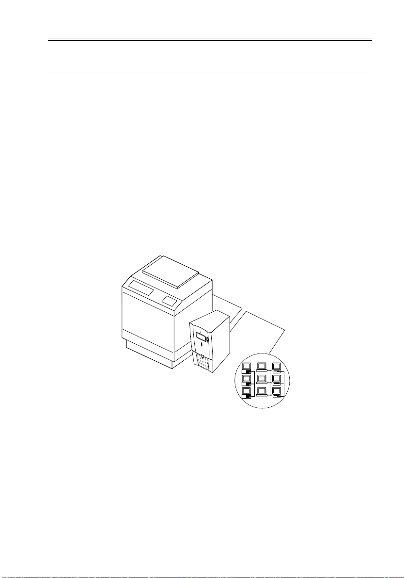
The iR-M2 adds computer connectivity and highly efficient Adobe PostScript 3 and PCL
printing capability to copiers. It is optimized for high-speed network communications, processing, rasterization, and printing.
The iR-M2, as an integral part of your organization’s printing system, enables users to:
• Send images over AppleTalk, TCP/IP, and IPX networks to print on iR-M2-supported
devices.
• Spool print jobs and select a printing priority for each job. Users can control spooled
print jobs sent to the iR-M2 with remote user software running on networked PC and
Mac OS computers.
• Print files in gray-scale and black and white.
• Use 136 resident fonts (126 Adobe Type 1 PostScript and 10 TrueType), plus two
Adobe Multiple Master fonts used for font substitution when printing PDF files. Fiery
Downloader™ or any third-party LaserWriter downloader, such as the Adobe Font
Downloader, can be used to download additional fonts.
COPYRIGHT
©
Copier
iR-M2
Networked computers
or work stations
F01-100-01 iR-M2 printing system
2002 CANON INC. 2000 2000 2000 2000 NM-PDL REV.0 JULY 2002
1-1

CHAPTER 1 INTRODUCTION
2 How the iR-M2 Operates
The iR-M2 enables users to print to the copier from networked PCs running Microsoft
Windows, from networked Mac OS computers, and from networked UNIX workstations
running TCP/IP.
The iR-M2 custom-designed boards and system software are responsible for efficient image processing and printing controls. The main functions of components and software are
described below.
The iR-M2 uses specialized circuit boards, the motherboard, and the copier interface
board to process image data for printing and scanning images.
The motherboard includes a 866MHz CPU that controls the image data transfer to and
from the copier interface board and runs the interpreter. The interpreter rasterizes the page
description file and then compresses the image pattern into memory using compression technology.
The interpreter sends compressed raster data through the image frame buffer memory to
the copier interface board. The copier interface board decompresses the image data and
sends it to the copier through the copier interface cable. The raster data supplied to the laser
in the copier charges the drum and renders the final image on paper at full copier engine
speed.
High-speed dual in-line memory modules (DIMMs) on the motherboard hold the image
data during printing. The iR-M2 is configured with one 128MB DIMM for a total of
128MB of memory.
1-2
COPYRIGHT
©
2002 CANON INC. 2000 2000 2000 2000 NM-PDL REV.0 JULY 2002
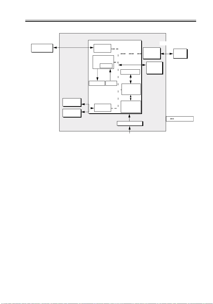
External Devices CopieriR-M2
Networked
computers
Network
interface
I/O Control
BIOS
Motherboard
CPU
CHAPTER 1 INTRODUCTION
Print
Copier
interface
board
User
interface
board
Copier
Hard disk
drive
CD-ROM
drive
Speaker
Reset
IDE
interface
Memory
Controller
Memory
Interpreter
Power supply
AC power
F01-200-01 iR-M2 functional diagram
PCI/
&
+3.3/+5/±12V DC
PCI Bus
COPYRIGHT
©
2002 CANON INC. 2000 2000 2000 2000 NM-PDL REV.0 JULY 2002
1-3

CHAPTER 1 INTRODUCTION
3 Print Options
The iR-M2’s efficient capabilities allow users to use a variety of applications to create and
print pages of text and/or images. The iR-M2 operates over a network.
Printing over a network allows users to print documents directly from applications in
which they were created. In addition, the iR-M2 offers an efficient way to print files that
have been saved as PostScript, Encapsulated PostScript (EPS), Portable Document Format
(PDF), or Tagged Image File Format (TIFF). These files can be downloaded directly to the
iR-M2 using Fiery Downloader, one of the remote utilities for use with the iR-M2.
1-4
COPYRIGHT
©
2002 CANON INC. 2000 2000 2000 2000 NM-PDL REV.0 JULY 2002

CHAPTER 1 INTRODUCTION
4 User Software
The following user software is provided on the User Software CD.
Adobe PS Printer Driver Enables users to print to the iR-M2 from Windows
9x/Me, Windows NT 4.0, Windows 2000, Windows
XP and Mac OS computers; also supports special iRM2 and PostScript 3 features.
PostScript Printer Files for use with the PostScript printer driver that
Description files (PPDs) allow the iR-M2 to appear in popular applications’
Print and Page Setup dialog boxes. The PPD provides information about the iR-M2 and the particular
copier model to the application and printer driver.
PostScript Screen Fonts PostScript screen fonts for the 136 PostScript printer
(for Mac OS only) fonts installed on the iR-M2 (126 Adobe Type 1 and
10 TrueType).
Fiery Downloader Enables the user to print PostScript, EPS, PDF, and
TIFF files directly to the iR-M2 without opening the
application in which they were created. Fiery
Downloader also enables the user to manage the
printer fonts installed on the iR-M2.
Fiery Spooler™ (Mac OS only) Enables the user to view the order and priority of
print jobs, customize printer settings for jobs, delete
jobs, move jobs between queues, and view job accounting information.
Fiery Scan Plug-in modules for Photoshop that enable the user
to scan images from the copier directly into the application.
Command WorkStation software Enables the operator to control the iR-M2 functions
from Windows 9x/Me/2000/XP and Windows NT
4.0 workstations. For more information on Command WorkStation, see the Job Management Guide.
Fiery Link™ Enables the customer to monitor the status of con-
nected.
COPYRIGHT
©
2002 CANON INC. 2000 2000 2000 2000 NM-PDL REV.0 JULY 2002
1-5

CHAPTER 1 INTRODUCTION
5 Fiery WebTools
The iR-M2 can support Internet or intranet access with Fiery WebTools™, which include
Status, WebSpooler, WebLink, and WebSetup. For more information on Fiery WebTools, see
the user documentation.
Fiery WebSetup is supported on Windows computers only.
1-6
COPYRIGHT
©
2002 CANON INC. 2000 2000 2000 2000 NM-PDL REV.0 JULY 2002

CHAPTER 2
PREPARING FOR INSTALLATION
COPYRIGHT
©
2002 CANON INC. 2000 2000 2000 2000 NM-PDL REV.0 JULY 2002

CHAPTER 2 PREPARING FOR INSTALLATION
1 Installation sequence
This chapter includes the following information:
• Summary of the installation sequence
• Checking the customer site
• Unpacking the iR-M2
• iR-M2 front and back overview
Familiarize yourself with this chapter and Chapter 3 of this Service Manual before you
attempt an installation. The installation sequence described in this chapter is designed to
make your job as easy as possible. Installation problems are easier to avoid and diagnose if
you proceed from the component to the system level and verify functionality at each stage.
F02-100-01 on page 2-2 outlines the recommended installation procedure for connecting
the iR-M2 to the copier.
Because the iR-M2 is a node on the customer’s computer network, make sure you coordinate your scheduled installation with the network administrator at the customer site. Refer
the network administrator to the Configuration Guide for network setup information.
COPYRIGHT
©
2002 CANON INC. 2000 2000 2000 2000 NM-PDL REV.0 JULY 2002
2-1

CHAPTER 2 PREPARING FOR INSTALLATION
Copier
iR-M2
Check installation
requirements and
Unpack the iR-M2,
verify site conditions;
page 2-3
Connect to the copier; page3-2
Print a Test Page and Conguration Page;
page 3-4
Network administrator connects the iR-M2 to the
network and veries the connection; see page 3-6 and
Network administrator congures Setup
Network administrator installs user software on
networked computers that print to the iR-M2; see
F02-100-01 Recommended installation steps and references
page 2-6
Initial startup;
page 3-1
Mac OS
computers
computers
Verify network operation
without the iR-M2 connected.
the Conguration Guide
options; see the Conguration Guide
Getting Started
Full iR-M2 functionality
PC
UNIX
workstaions
2-2
COPYRIGHT
©
2002 CANON INC. 2000 2000 2000 2000 NM-PDL REV.0 JULY 2002
CHAPTER 2 PREPARING FOR INSTALLATION
2 Checking the customer site
Before you install the iR-M2, check site conditions and inform the customer of any
installation requirements.
2.1 Copier Model
■ What copier model is installed?
■ Is the service mode COPIER>OPTION>INT-FACE>IMG–CONT set to 4?
■ Has the INTERFACE BOARD been installed on the copier?
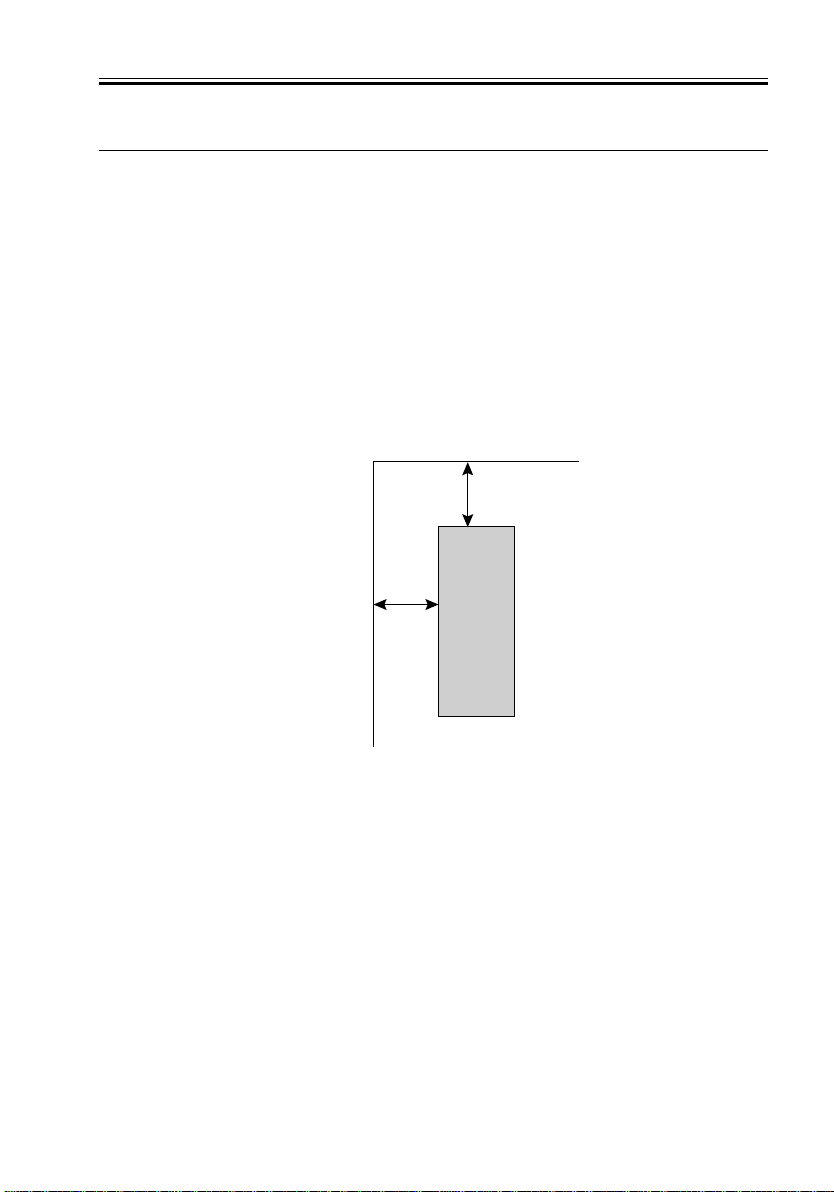
■ Is there space near the copier for the iR-M2?
Make sure that there is space for the iR-M2. Allow enough space at the back panel for
the cables to route easily and at the side panel so that the iR-M2 does not interfere with
use of or service to the copier (such as clearing a paper jam). You may need to move the
copier out from the wall so that its interface connectors are accessible.
20cm / 8inch min.
Back side
20cm / 8inch min.
F02-201-01
■ Does the copier require service or adjustments?
Copy the copier test page before you install the iR-M2.
After getting approval, complete the copier service needed.
COPYRIGHT
©
2002 CANON INC. 2000 2000 2000 2000 NM-PDL REV.0 JULY 2002
iR-M2
Front side
2-3

CHAPTER 2 PREPARING FOR INSTALLATION
2.2 Power
■ Is there a dedicated, grounded electrical outlet near the copier for the iR-M2?
Locate the grounded electrical outlet that will supply power to the iR-M2. You should
not run the iR-M2 and the copier on the same circuit. Make sure to use a surge suppressor for the iR-M2 if the customer has provided one.
• Do not use a 3-prong adapter in a 2-hole ungrounded outlet.
• Do not use an extension cord.
• Do not plug the iR-M2 into a circuit with heating or refrigeration equipment
(including water coolers).
• Do not plug the iR-M2 into a switchable wall outlet. This can result in the iR-M2 being turned off accidentally.
2.3 Network
■ What is the network cable and connection type?
• Unshielded twisted pair (10BaseT/100BaseT)
• Optional Token Ring (shielded twisted pair or unshielded twisted pair?)
■ Is the network connection ready and tested for iR-M2 installation?
To verify that the network is functioning before you attach the iR-M2:
• Ask the network administrator to print a document on a shared printer over the network.
• Ask the network administrator to verify the computer and network requirements as
specified in Getting Started.
2.4 Parallel Port
■ Is there space for both the iR-M2 and the PC that will be connected to the iR-M2?
2.5 System Contact Person
■ Will the person responsible for the computers and the network be available at the time
set for installation? Get a name as a contact.
2-4
COPYRIGHT
©
2002 CANON INC. 2000 2000 2000 2000 NM-PDL REV.0 JULY 2002

CHAPTER 2 PREPARING FOR INSTALLATION
2.6 Setting customer expectations
If the site is ready, installation takes about one hour. The customer should be informed of
the following:
• Some nodes on the network may be unavailable for up to one hour.
• The copier may be unavailable for up to one hour.
• The network administrator needs to be available during the installation for network
connectivity.
Equipment downtime and impact on the network can be minimized if the network administrator installs a network connector for the iR-M2 and confirms network functionality with the connector in place before the date scheduled for the iR-M2 installation.
• The network administrator should have a networked computer available during the
installation. The appropriate software should already be installed. Documentation for
the networked computer and the network operating software should be available.
• The network administrator should install the user software shipped with the iR-M2
(user documentation is also included) onto networked PC and Mac OS computers that
will print to the iR-M2.
This guide covers hardware installation and service. It provides general information on connecting the iR-M2 to the customer’s network. Network
Memo
setup and configuration information goes beyond the scope of this guide.
For network setup and configuration information, refer the network administrator to the Configuration Guide.
COPYRIGHT
©
2002 CANON INC. 2000 2000 2000 2000 NM-PDL REV.0 JULY 2002
2-5

CHAPTER 2 PREPARING FOR INSTALLATION
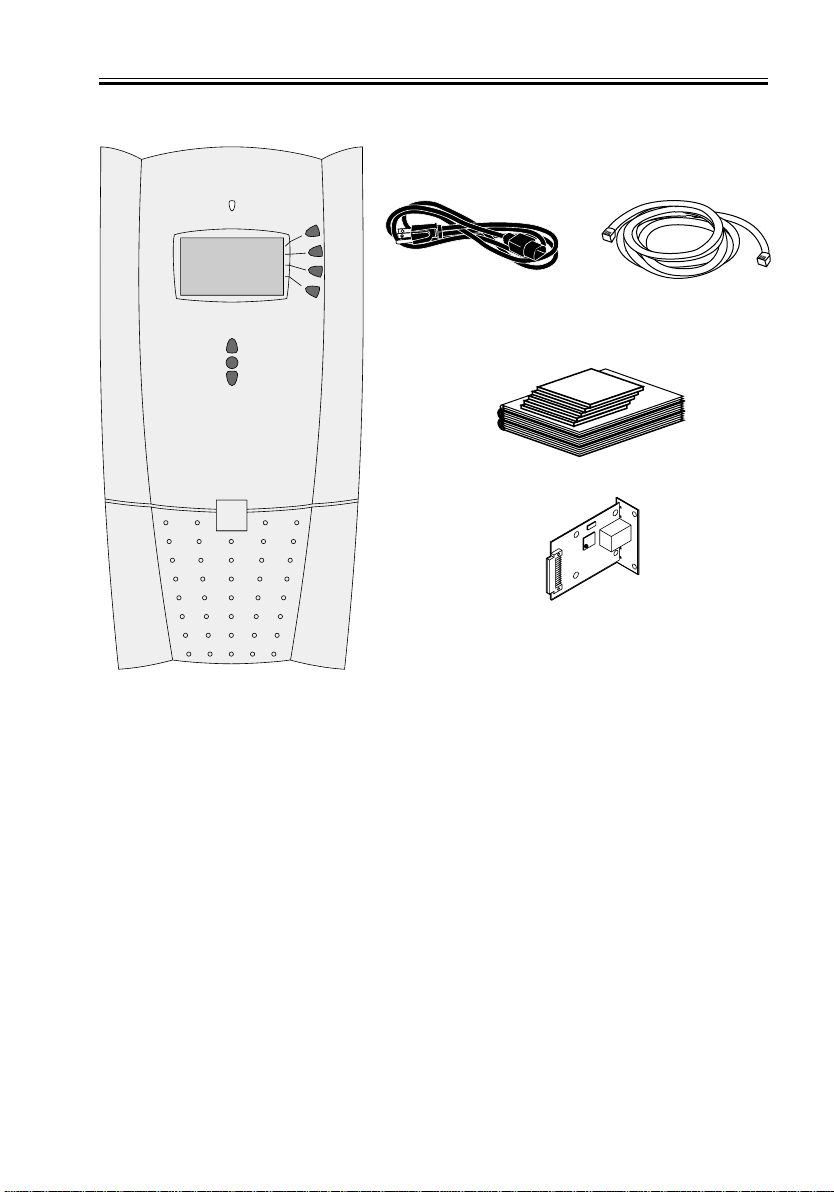
3 Unpacking the iR-M2
The iR-M2 is assembled and shipped from the factory in a box that includes all necessary
cables and documentation, as shown in F02-301-01 on page 2-7.
3.1 To Unpack the iR-M2
1. Open the box and remove the packing material.
You may want to save the original boxes and packing materials if you need to transport
the iR-M2 at a later date.
2. Remove the contents from the top container. Inspect the contents for visible damage.
The top container should include the following items:
• Bags containing one copier interface cable and one AC power cable
• Network Interface Adapter
• Media package (includes CDs for user software, user documentation and system soft-
ware CD)
System software is for service use only.
3. Give the media package to the customer or the network administrator.
Let the customer or network administrator know that in order to take full advantage of
the iR-M2, the user software must be installed on computers that will print to the iRM2.
4. Set aside the remaining components from the top container.
5. Remove the top container and any packing materials.
Set aside the packing material and note the orientation of the iR-M2 inside the shipping
container, in case you need to repack it later.
6. Carefully lift the iR-M2 out of the box.
If you notice shipping damage to any component, be sure to save the shipping container
in case the carrier needs to see it. Call the carrier immediately to report the damage and
file a claim, then call your authorized service/support center. Be ready to furnish the se-
2-6
COPYRIGHT
©
2002 CANON INC. 2000 2000 2000 2000 NM-PDL REV.0 JULY 2002
CHAPTER 2 PREPARING FOR INSTALLATION
rial number printed on the back of the iR-M2.
Power cable
iR-M2
F02-301-01 Contents of iR-M2 shipping box
Copier interface cable
Media pack
Network Interface Adapter
COPYRIGHT
©
2002 CANON INC. 2000 2000 2000 2000 NM-PDL REV.0 JULY 2002
2-7
CHAPTER 2 PREPARING FOR INSTALLATION
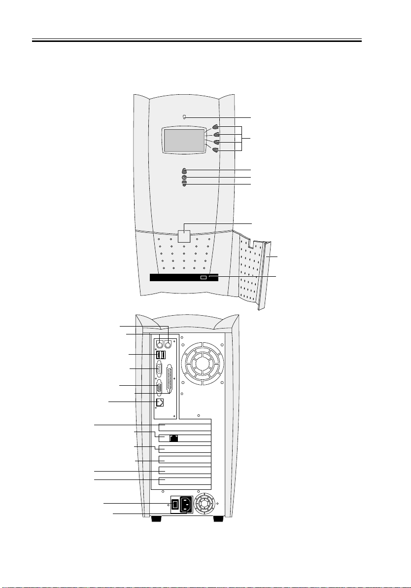
3.2 Front and back panels
After unpacking the iR-M2, familiarize yourself with the front and back panels before
you connect it to the copier.
Activity light
First
Line selection
buttons
Fourth
Up button
Menu button
Down button
Jewel
Drive door
CD-ROM drive
Front panel
Mouse (not used)
Keyboard (not used)
USB ports (not used)
Serial port (not used)
Monitor (not used)
Parallel port (not used)
10/100BaseT
Empty slot
Copier interface board
Empty slot (reserved
for Token Ring option)
Empty slot (reserved
for parallel port option)
Empty slot
Empty slot
Power switch
Power connector
2-8
Back panel
F02-302-01 Front and back panels
COPYRIGHT
©
2002 CANON INC. 2000 2000 2000 2000 NM-PDL REV.0 JULY 2002

CHAPTER 3
CONNECTING THE iR-M2
COPYRIGHT
©
2002 CANON INC. 2000 2000 2000 2000 NM-PDL REV.0 JULY 2002
CHAPTER 3 CONNECTING THE iR-M2
1 Installation
After you unpack or service the iR-M2, power on the system and allow diagnostics to run
before you connect the iR-M2 to the copier and the network. Diagnostics run automatically
during startup to check the iR-M2 for internal problems.
1.1 Preliminary Checkout
The following procedure describes how to connect power and start the iR-M2.
1.1.1 TO CONNECT POWER AND START THE iR-M2
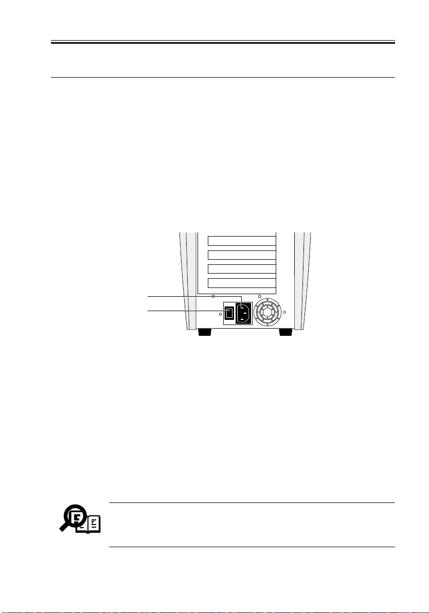
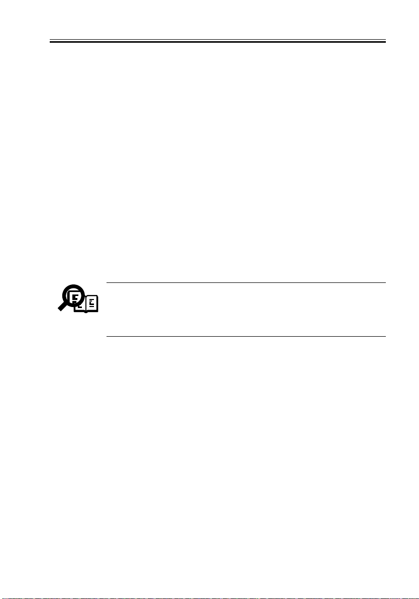
1. Connect the power cable to the power connector at the back of the iR-M2 (see F03-101-
01 below).
2. Make sure the power switch is in the off position (press 0), and then connect the other
end of the power cable to a wall outlet.
Power connector
Power switch
F03-101-01 iR-M2 power
3. Power on the iR-M2 using the power switch on the back panel. The power supply auto-
matically senses the correct voltage.
4. Allow startup to proceed without interruption while you watch the iR-M2 Control Panel.
Do not press any buttons on the Control Panel.
5. Wait for the iR-M2 to reach the Idle screen to confirm that the iR-M2 is operating prop-
erly.
When the iR-M2 reaches the Idle screen, you are ready shut down and connect the network and copier interface cables. Setup options should be configured after making these
connections. The network administrator is responsible for configuring Setup according
to the network and user environment. Refer the network administrator to the Configuration Guide for Setup information.
The message Copier connection failure. Reboot may appear on the Control
Panel the startup process is complete. After you shut down the iR-M2, connect the it to the copier, and then power back on, the message will no longer
Memo
appear.
6. Following a successful startup, shut down the iR-M2 (see page 3-15).
COPYRIGHT
©
2002 CANON INC. 2000 2000 2000 2000 NM-PDL REV.0 JULY 2002
3-1

CHAPTER 3 CONNECTING THE iR-M2
1.2 Connecting to the Copier
After completing the preliminary checkout, connect the iR-M2 to the copier. The iR-M2
communicates with the copier through a cable from the copier interface board to the interface port on the copier.
1.2.1 TO CONNECT TO THE COPIER
1. Power off the copier.
Check with the network administrator or supervisor before powering off the copier.
2. Connect one end of the copier interface cable to the interface connector on the copier
and the other end of the cable to the iR-M2 copier interface connector (see F03-102-01
below).
3-2
Slot1
Slot2
Slot3
Slot4
Slot5
Slot6
Copier interface port (RJ-45)
F03-102-01 Copier interface connection
COPYRIGHT
©
2002 CANON INC. 2000 2000 2000 2000 NM-PDL REV.0 JULY 2002
Copier interface cable
CHAPTER 3 CONNECTING THE iR-M2
1.3 Verifying the Connection
After you connect the iR-M2 to the copier, print the PS and PCL Test Pages and the Con-
figuration page to verify that the connection between the iR-M2 and the copier is good.
1.3.1 Printing the Test Pages and Configuration page
Before connecting the iR-M2 to the network, print the PS and PCL Test Pages and the
Configuration page.
• PS and PCL Test Pages—printing the PS and PCL Test Pages verifies that all the components of the iR-M2-to-copier interface are working. The Test Page are files that reside
on the HDD (hard disk drive).
• Configuration page—printing the Configuration page can be helpful during installation,
setup, and service. After you install the iR-M2 and before any default settings are
changed, you can obtain a record of the defaults by printing the Configuration page.
After you make the physical connection to the network, the network administrator can
customize Setup options according to the network and user environment. Using the
Configuration page as a guide can help speed up this process. For more information, see
the Configuration Guide.
Before you perform any service procedure, you should print the Configuration page, if
possible, so that you can return the settings to their former configuration, if necessary.
The iR-M2 supports the iR8500/iR7200/iR105/iR85. In the meantime, be
sure to execute Factory Default before you connect the iR-M2 which is
Memo
once connected to a certain copier or printer to another type of copier or
printer. Executing Factory Default enables the iR-M2 to be connected to another type of or printer.
COPYRIGHT
©
2002 CANON INC. 2000 2000 2000 2000 NM-PDL REV.0 JULY 2002
3-3
CHAPTER 3 CONNECTING THE iR-M2
a. T O PRINT THE TEST P A GES
1. Power on the copier and allow it to warm up.
The iR-M2 starts automatically when you power on the copier. Wait as the iR-M2 runs
through its startup diagnostics.
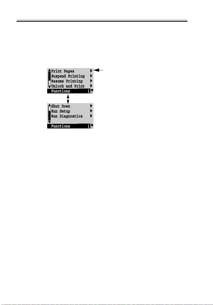
2. At the Idle screen, press the Menu button once (see “Using the Control Panel” on page
3-8). The Functions menu appears.
Use the Up and Down buttons to
scroll through these options. Use
the line selection buttons to the
right to select Print Pages.
3. Press the line selection button to the right of Print Pages. and then select PS Test Page.
The iR-M2 sends the PS Test Page to the copier.
4. Press the line selection button to the right of Print Pages. and then select PCL Test Page.
The iR-M2 sends the PCL Test Page to the copier.
5. Examine the quality of the Test Pages.
The Test Pages confirm that the iR-M2 is functional and that the connection between the
iR-M2 and the copier is good. When you examine the Test Pages, keep in mind that:
• All patches should be visible, even though they may be very faint in the 5% and 2%
range.
• Each patch set should show uniform gradation from patch to patch as the shade light-
ens from 100% to 0%.
Poor image quality may indicate a need to service the copier. For more information, see
the documentation provided with the copier.
3-4
COPYRIGHT
©
2002 CANON INC. 2000 2000 2000 2000 NM-PDL REV.0 JULY 2002
 Loading...