

Canon FY8-13HR-000, iR-M1, image PASS-M1, Unir-M1 Service Manual
Network Multi-PDL
Printer Unit-M1/
image PASS-M1
REVISION 0
JULY 2001
COPYRIGHT© 2001 CANON INC. NM-PDL REV.0 JULY 2001 PRINTED IN U.S.A.
FY8-13HR-000

IMPORTANT
THE INFORMATION CONTAINED HEREIN IS PUBLISHED BY CANON, INC., JAPAN.
SPECIFICATIONS AND OTHER INFORMATION CONTAINED HEREIN MAY DIFFER
SLIGHTLY FROM ACTUAL MACHINE VALUES OR THOSE FOUND IN ADVERTISING AND
OTHER PRINTED MATTER.
ANY QUESTIONS REGARDING INFORMATION CONTAINED HEREIN SHOULD BE
DIRECTED TO THE COPIER SERVICE DEPARTMENT OF THE SALES COMPANY.
COPYRIGHT © 2001 CANON INC.
Printed in U.S.A.
CAUTION
Use of this manual should be strictly supervised to avoid disclosure of confidential information.
COPYRIGHT© 2001 CANON INC. NM-PDL REV.0 JULY 2001 PRINTED IN U.S.A.
Preface
The Installation and Service Guide is intended for certified Network Multi-PDL Printer
Unit-M1 ™/image PASS-M1 service technicians installing or servicing a Network MultiPDL Printer Unit-M1/image PASS-M1. If you have not received installation and service certification, you should not attempt to install or service a Network Multi-PDL Printer UnitM1/image PASS-M1. Electronics For Imaging does not warrant the performance of a iR-M1
if installed or serviced by non-certified personnel.
About this guide
The term “iR-M1” is used in this manual to refer to the Network Multi-PDL
Printer Unit-M1/image PASS-M1. The term “copier” is used to refer to the
Memo
This guide is divided into the following sections:
• “Preface”
General information about this guide and about installing the iR-M1.
• Chapter 1, “Introduction”
General information about the iR-M1.
• Chapter 2, “Preparing for Installation”
Unpacking and the steps you need to take before you install the unit.
• Chapter 3, “Connecting the iR-M1”
How to connect the iR-M1 to the copier and the network and verify that the system is
working correctly; overview of Control Panel.
• Chapter 4, “Service Procedures”
Removal and replacement procedures for iR-M1 components.
• Chapter 5, “Troubleshooting Procedures”
Common problems and ways of correcting them; startup errors.
Canon iR 8500 copier.
iR-M1 customers should not use this technical service documentation.
Please don’t leave your copy of the Installation and Service Guide behind
after you make a service call.
Memo
About the illustrations in this guide
The illustrations in this guide reflect the current shipping version of the iR-M1 at the time
of publication. Components shown in these illustrations are subject to change. To receive
information about any iR-M1 components that do not match illustrations in this guide, contact your authorized service/support center.
COPYRIGHT
©
2001 CANON INC. 2000 2000 2000 2000 NM-PDL REV.0 JULY 2001
i
Terminology and conventions
The term “network administrator” refers to the person responsible for maintaining the net-
work at the customer site.
The term “Control Panel” refers to the area on the front of the iR-M1 including the green/
red activity light and the display window (LCD—liquid crystal display), and the black oval
plastic disk surrounding the display window.
The term “system software” refers to the software installed on the iR-M1 hard disk drive.
The term “PC” refers to any IBM PC or compatible computer running Windows.
The term “10BaseT” is used throughout this manual to refer to 10BaseTX.
The term “100BaseT” is used throughout this manual to refer to 100BaseTX.
References to other iR-M1 manuals, such as the Configuration Guide, are displayed in
italics.
The note indicator highlights important messages and additional information.
Memo
The caution icon indicates a need for special care and safety when handling
the equipment.
ii
COPYRIGHT
©
2001 CANON INC. 2000 2000 2000 2000 NM-PDL REV.0 JULY 2001

Contents
CHAPTER 1 INTRODUCTION
1 Features ........................................ 1-1
2 How the iR-M1 Operates ............. 1-2
3 Print Options ................................ 1-3
CHAPTER 2 PREPARING FOR INSTALLATION
1 Outline .......................................... 2-1
2 Checking the Customer Site ......... 2-3
2.1 Copier Model ........................ 2-3
2.2 Power .................................... 2-3
2.3 Network ................................ 2-4
2.4 Parallel Port........................... 2-4
CHAPTER 3 INSTALLATION
1 Installation .................................... 3-1
1.1 Preliminary Checkout ........... 3-1
1.1.1 To Connect Power and
Start the iR-M1 .............. 3-1
1.2 Connecting to the Copier ...... 3-3
1.2.1 To Connect the iR-M1
to the Copier .................. 3-3
1.3 Verifying the Connection ...... 3-4
1.3.1 Printing the iR-M1
Test Pages ...................... 3-4
1.4 Installing Additional
Options .................................. 3-5
1.5 Connecting to the Network ... 3-5
1.5.1 To Connect a Twisted Pair
Cable to the iR-M1 ........ 3-6
2 Connecting a PC to
the Parallel Port ............................ 3-7
4 User Software ............................... 1-4
5 Fiery WebTools ............................. 1-5
2.5 System Contact Person ......... 2-4
2.6 Setting Customer
Expectations .......................... 2-5
3 Unpacking the iR-M1 ................... 2-6
3.1 To Unpack the iR-M1 ........... 2-6
3.2 iR-M1 Panels ........................ 2-8
2.1 To Connect the iR-M1 to
a PC ....................................... 3-7
2.2 Using the Control Panel ........ 3-9
2.2.1 Activity Light .............. 3-10
2.2.2 Buttons ........................ 3-10
2.2.3 Control Panel Screens
and Icons ..................... 3-11
2.3 Functions Menu .................. 3-14
3 Shutting Down and Restarting
the iR-M1 ................................... 3-15
3.1 To Shout Down
the iR-M1 ............................ 3-15
3.2 To Restart the iR-M1 .......... 3-15
3.3 To Reboot the System ......... 3-15
COPYRIGHT
©
2001 CANON INC. 2000 2000 2000 2000 NM-PDL REV.0 JULY 2001
iii

CHAPTER 4 DISASSEMBLY/ASSEMBLY
1 Before Disassembling the Unit .... 4-1
1.1 Overview ............................... 4-1
1.2 System Software Service ...... 4-1
1.3 Accessing Internal
Components .......................... 4-3
1.3.1 To Shout Down
the iR-M1 ...................... 4-3
2 Externals ....................................... 4-4
2.1 To Open the iR-M1 ............... 4-4
2.2 Accessing Front Panel
Components .......................... 4-6
2.2.1 To Remove
the Front Panel .............. 4-6
2.2.2 To Replace
the Front Panel .............. 4-7
3 Checking Internal Connections .... 4-8
3.1 To Check Board and
Cable Connections ................ 4-8
3.2 To Check Motherboard DIMM
Connections ........................ 4-10
3.3 Restoring Functionality After
Service ................................ 4-11
3.3.1 To Reassemble
the iR-M1 .................... 4-11
4 Electrical Parts ............................ 4-13
4.1 Outline ................................ 4-13
4.2 User Interface Board ........... 4-13
4.2.1 To Remove the UIB ..... 4-14
4.2.2 To Replace the UIB ..... 4-15
4.3 Copier Interface Board........ 4-16
4.3.1 To Remove the Copier
Interface Board ............ 4-16
4.3.2 To Replace the Copier
Interface Board ............ 4-16
4.4 Motherboard ....................... 4-17
4.4.1 Removing the iR-M1
Motherboard ................ 4-18
4.5 Replacing Parts on
the Motherboard .................. 4-20
4.5.1 DIMM ......................... 4-20
4.5.2 Motherboard
Battery ......................... 4-21
4.6 Fans ..................................... 4-22
4.6.1 Exhaust Fan ................. 4-22
4.6.2 CPU Fan ...................... 4-24
4.6.3 Power Switch............... 4-25
4.7 Power Supply ...................... 4-28
4.7.1 To Remove
the Power Supply ........ 4-29
4.7.2 To Replace
the Power Supply ........ 4-29
4.7.3 Power Supply Cable
Voltages ....................... 4-31
4.8 Hard Disk Drive .................. 4-32
4.8.1 Proper Handling .......... 4-32
4.9 Front Panel Components..... 4-34
4.9.1 Jewels .......................... 4-35
4.9.2 Buttons ........................ 4-35
5 Installing the System Software ... 4-36
5.1 Download Tool .................... 4-36
5.1.1 Outline ......................... 4-36
5.1.2 Installing the Download
Tool .............................. 4-37
5.2 Installing the System
Software .............................. 4-39
5.2.1 Caution ........................ 4-39
5.2.2 Items to Prepare ........... 4-39
5.2.3 Preparing the iR-M1 .... 4-39
5.2.4 Preparing the PC ......... 4-39
5.2.5 Connecting the iR-M1
and the PC ................... 4-40
5.2.6 Operating the iR-M1 ... 4-40
5.2.7 Operating the PC ......... 4-41
iv
COPYRIGHT
©
2001 CANON INC. 2000 2000 2000 2000 NM-PDL REV.0 JULY 2001

CHAPTER 5 TROUBLESHOOTING
1 Preliminary On-site Checkout ...... 5-1
1.1 The Troubleshooting
Process .................................. 5-1
1.2 Where Problems Occur ......... 5-2
1.3 Before You Go to
the Customer Site .................. 5-3
1.4 Preliminary On-site
Checkout ............................... 5-5
1.4.1 Checking Interface
Cables ............................ 5-5
1.4.2 Checking Internal
Components ................... 5-6
2 Checking the iR-M1 as
a Stand-alone Unit ........................ 5-8
2.1 To Isolate the iR-M1 ............. 5-8
2.2 General iR-M1 System Error
Conditions ............................. 5-8
3 iR-M1 Diagnostic Sets ............... 5-11
3.1 To Run iR-M1 Start Up
Diagnostics ......................... 5-11
3.2 To Run iR-M1 Custom
Diagnostics ......................... 5-12
4 Checking the Entire iR-M1
System ........................................ 5-14
4.1 Checking the Copier
Interface .............................. 5-14
4.1.1 Printing the Test
4.2 Checking Network
Connections ........................ 5-15
4.3 Printing to the iR-M1 .......... 5-16
CHAPTER 6 PARTS CATALOG
APPENDIX
1 Specifications .............................. A-1
1.1 Hardware Features ............... A-1
1.2 Networking and
Connectivity ......................... A-1
1.3 User Software ...................... A-1
1.4 Safety and Emissions
Compliance .......................... A-1
1.4.1 Safety Approvals .......... A-1
1.4.2 EMI Approvals ............. A-1
Pages ............................ 5-14
COPYRIGHT
©
2001 CANON INC. 2000 2000 2000 2000 NM-PDL REV.0 JULY 2001
v

Precautions
Always observe the following general precautions when installing and servicing the iR-
M1:
1. Report any shipping damage.
If there is any evidence of shipping or handling damage to the iR-M1 packing boxes or
their contents, save the damaged boxes and parts, call the shipper immediately to file a
claim and notify your authorized service/support center.
2. Never alter an existing network without permission.
The iR-M1 will probably be connected to an existing Local Area Network (LAN) based
on Ethernet hardware. The network is the link between the customer’s computer, existing copier, and other equipment. Never disturb the LAN by breaking or making a network connection, altering termination, installing or removing networking hardware or
software, or shutting down networked devices without the knowledge and express permission of the network administrator or the shop supervisor.
3. Never enter an IP address in iR-M1 Network Setup.
Only the network administrator should enter an IP address on a network device.
Assigning a iR-M1 an incorrect IP address can cause unpredictable errors on any or all
devices connected to the network.
4. Always disconnect power before opening the iR-M1 chassis.
Although iR-M1 circuitry operates on 3.3V DC, 5V DC, and ±12V DC, 100-240V AC
is present when the chassis cover is removed. Inside the chassis, the power supply is not
encased. Before you service the iR-M1, shut it down completely and unplug the AC
power cable from the back.
5. Handle the iR-M1 glass display window with care.
If the glass on the user interface board breaks and the liquid crystal inside leaks out,
avoid contact with it. If you do come in contact with the liquid crystal, wash it off with
soap and water immediately.
Avoid pressing the surface of the glass display window. Applying pressure to the glass
display window on the user interface board will cause it to change color.
Use a soft cloth moistened with isopropyl or ethyl alcohol to clean the glass display
window. Other solvents, such as water, may damage the polarizer.
vi
COPYRIGHT
©
2001 CANON INC. 2000 2000 2000 2000 NM-PDL REV.0 JULY 2001

6. Follow standard ESD (electrostatic discharge) precautions while working on the internal
components of the iR-M1.
Static is always a concern when servicing electronic devices. It is highly unlikely that
the area around the copier and the iR-M1 is static-free. Carpeting, leather-soled shoes,
synthetic clothing fibers, silks, and plastics may generate a static charge of more than
10,000 volts. Static discharge is capable of destroying the circuits etched in silicon microchips, or dramatically shortening their life span. By observing standard precautions,
you may avoid extra service calls and save the cost of a new board.
When possible, work on a ground-connected antistatic mat. Wear an antistatic wristband, grounded at the same place as the antistatic mat. If that is not possible:
• Attach a grounding strap to your wrist. Attach the other end to a good ground.
• When you unpack the iR-M1 from the carton for the first time, touch a metal area to
discharge the static on your body.
• Before you handle internal components, touch a metal part of the iR-M1.
• Leave new electronic components inside their antistatic bags until you are ready to
install them. When you remove components from an antistatic bag, place them on a
grounded antistatic surface, component-side up.
• When you remove an electronic component, place it into an antistatic bag immedi-
ately. Do not walk across a carpet or vinyl floor while carrying an unprotected board.
7. Handle printed circuit boards by opposing edges only, but avoid touching the contacts
on the edge of the board.
8. Use care when handling parts of the iR-M1 as some edges on the unit may be sharp. For
example, be careful when:
• Plugging in cables at the back of the unit
• Using the power switch to power on/off the unit
9. Never set a cup of coffee—or any liquid—on or near the iR-M1 or the copier.
COPYRIGHT
©
2001 CANON INC. 2000 2000 2000 2000 NM-PDL REV.0 JULY 2001
vii

Tools you will need
To install or service the iR-M1, you should bring the following tools:
• ESD wrist grounding strap
• Antistatic mat
• Wire cutters
• #1 and #2 Phillips head screwdrivers (non-magnetic)
• Small flat-blade screwdriver (non-magnetic)
• 3/16" hex nut driver
• Small needlenose pliers
• M3 metric wrench
• Flashlight
Also recommended:
• Ribbon cable connector extractor
You should also bring this guide and any technical notes you may have for the iR-M1.
viii
COPYRIGHT
©
2001 CANON INC. 2000 2000 2000 2000 NM-PDL REV.0 JULY 2001

CHAPTER 1
INTRODUCTION
COPYRIGHT
©
2001 CANON INC. 2000 2000 2000 2000 NM-PDL REV.0 JULY 2001

CHAPTER 1 INTRODUCTION
1 Features
The iR-M1 server adds highly efficient printing capacity to a black and white copier. It is
optimized for high-speed network communications, processing, rasterization, and printing
of continuous tone black and white and monochrome pages.
The iR-M1 is an integral part of a printing system that includes networked computers running Windows, Mac OS, and UNIX. The iR-M1 enables users to:
• Take advantage of printing features of Macintosh and Windows 95/98/Me, Windows
NT, and Windows 2000 Professional.
• Send images over AppleTalk, TCP/IP, and Novell networks and print to a iR-M1 supported copier.
• Send images through a PC connected to the parallel port and print to a iR-M1 supported copier.
• Spool print jobs and select a printing priority for each job.
• Use iR-M1 user software running on networked PC and Mac OS computers to control
spooled print jobs sent to the iR-M1.
• Print text and images in grayscale, and black and white.
• Use resident PostScript and PCL fonts. Fiery Downloader can be used to download additional fonts as needed.
Networked
computers
Copier
COPYRIGHT
©
iR-M1
F01-100-01 iR-M1 printing system
2001 CANON INC. 2000 2000 2000 2000 NM-PDL REV.0 JULY 2001
PC
1-1
CHAPTER 1 INTRODUCTION
2 How the iR-M1 Operates
The iR-M1 enables the customer to access the copier through the network and use it to
print files using advanced spooling and job control functions. Users can print to the iR-M1
from networked PCs, Mac OS computers, and UNIX workstations running TCP/IP. In addition, the iR-M1 parallel port can be used to print directly from a connected PC.
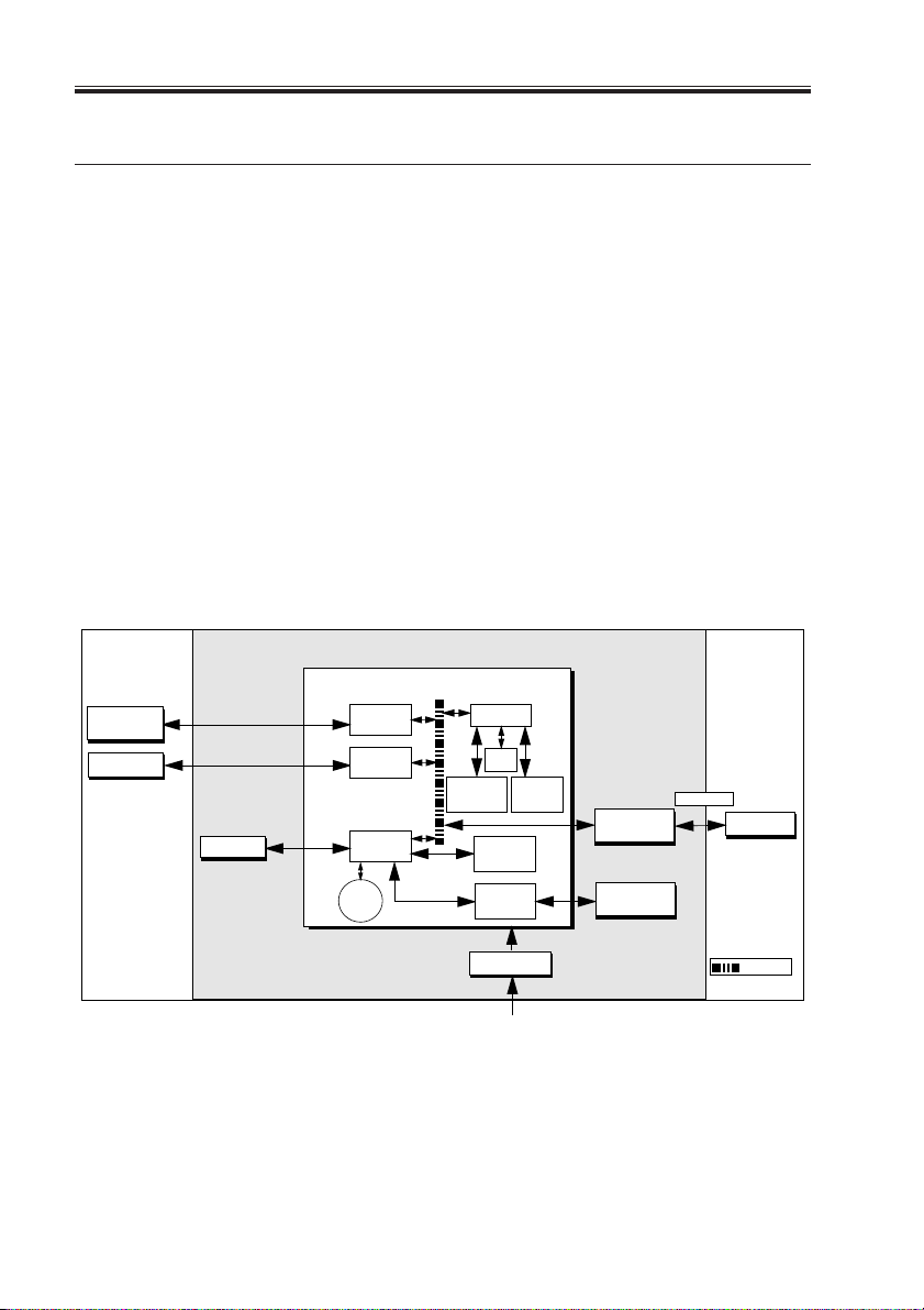
The iR-M1 custom-designed boards and system software are responsible for efficient image processing and printing controls. The main functions of iR-M1 components and software are described below.
The iR-M1 uses a specialized motherboard to process image data for printing images. The
motherboard includes a Intel Mobile Pentium III 500MHz CPU. The PostScript Interpreter
interprets the page description file. The RipChip ™ on the motherboard controls data management and other system functions, freeing up the CPU for efficient image data processing.
High-speed DIMMs (dual in-line memory modules) on the motherboard hold the image
data during printing. The iR-M1 is originally configured for a minimum of 128MB of
memory.
External devices
Networked
computers
PC
1-2
Motherboard
Network
interface
Parallel
HDD
interface
PCI-ISA
Battery
RTC/
Memory &
Interpreter
Super I/O
Power supply
AC power 100-240V AC
F01-200-01 iR-M1 functional diagram
COPYRIGHT
©
2001 CANON INC. 2000 2000 2000 2000 NM-PDL REV.0 JULY 2001
RipChip
Flash
controller
UIB
interface
CPU
+5/±12VDC
Copier
interface board
User interface
board
CopieriR-M1
Print
Copier
PCI Bus

CHAPTER 1 INTRODUCTION
3 Print Options
The iR-M1’s efficient capabilities allow customers to use a variety of applications to cre-
ate and print pages of text and/or images over a network or through the parallel port.
Because the iR-M1 has the ability to print part of a file while processing another part of
the file (RIP-While-Print ™ ), it is capable of printing files at full copier speeds.
Users printing over a network can print files directly from the applications in which they
were created. The iR-M1 also offers an efficient way to print files that have been saved in
PostScript, Encapsulated PostScript (EPS), or Portable Document Format (PDF). These files
can be downloaded directly to the iR-M1 using Fiery Downloader ™ , a remote utility provided with the iR-M1.
Users can print files from a PC directly connected to the iR-M1’s parallel port. PostScript
files can be printed over the parallel port from Windows, including the MS-DOS window,
and from various Windows applications running on the PC.
COPYRIGHT
©
2001 CANON INC. 2000 2000 2000 2000 NM-PDL REV.0 JULY 2001
1-3

CHAPTER 1 INTRODUCTION
4 User Software
iR-M1 user software is provided on the User Software CD. Some of the software can also
be installed from the Fiery WebTools Installer (see Getting Started for more information on
WebTools). The network administrator or the user at the customer site is responsible for installing software onto computers that will use the iR-M1 over a network.
The following software is included on the User Software CD:
1-4
COPYRIGHT
©
2001 CANON INC. 2000 2000 2000 2000 NM-PDL REV.0 JULY 2001

CHAPTER 1 INTRODUCTION
5 Fiery WebTools
The iR-M1 can support Internet or intranet access with Fiery WebTools. WebTools include Status, WebSpooler, Installer, WebDownloader, WebSetup, and WebLink. For more
information about WebTools, see the Configuration Guide and the Printing Guide.
COPYRIGHT
©
2001 CANON INC. 2000 2000 2000 2000 NM-PDL REV.0 JULY 2001
1-5

CHAPTER 2
PREPARING FOR INSTALLATION
COPYRIGHT
©
2001 CANON INC. 2000 2000 2000 2000 NM-PDL REV.0 JULY 2001

CHAPTER 2 PREPARING FOR INSTALLATION
1 Outline
This chapter includes the following information:
• Summary of the installation sequence
• Checking the customer site
• Unpacking the iR-M1
• iR-M1 front and back overview
Familiarize yourself with Chapters 2 and 3 of this guide before you attempt an installation. The installation sequence described in this chapter is designed to make your job as
easy as possible. Installation problems are easier to avoid and diagnose if you proceed from
the component to the system level and verify functionality at each stage.
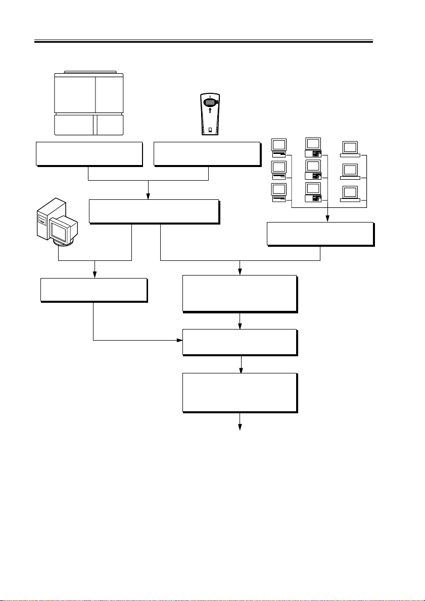
F02-100-01 on page 2-2 outlines the recommended installation procedure for connecting
the iR-M1 to the copier.
Because the iR-M1 is a node on the customer’s computer network, make sure that you coordinate your scheduled installation with the network administrator at the customer site. Refer the network administrator to the Configuration Guide for network Setup information.
COPYRIGHT
©
2001 CANON INC. 2000 2000 2000 2000 NM-PDL REV.0 JULY 2001
2-1
CHAPTER 2 PREPARING FOR INSTALLATION
Copier
iR-M1
Check installation requirements
and verify site conditions,
page 2-3.
PC
Connect copier interface cable, page 3-3.
Print the iR-M1 Test Pages, page 3-4.
Connect a PC to the iR-M1 parallel
port, page 3-7.
Unpack the iR-M1, page 2-6.
Initial startup, page 3-1.
Network administrator connects the
iR-M1 to the network and verifies
the connection (see the Configuration
Guide).
Network administrator configures
Setup options (see the Configuration
Guide).
Network administrator installs the
iR-M1 user software on networked
computers that will print to the iR-M1
(see Getting Started).
Mac OS
computers
Verify network operation without
the iR-M1 connected.
PCs
workstations
UNIX
2-2
Full iR-M1 functionality
F02-100-01 Recommended installation steps and references
COPYRIGHT
©
2001 CANON INC. 2000 2000 2000 2000 NM-PDL REV.0 JULY 2001

CHAPTER 2 PREPARING FOR INSTALLATION
2 Checking the Customer Site
Before you install the iR-M1, check site conditions and inform the customer of any installation requirements.
2.1 Copier Model
■ What copier model is installed?
■ Is there space near the copier for the iR-M1?
Make sure there is space for the iR-M1. You may need to move the copier out from the
wall for easier access.
■ Does the copier require service or adjustment?
Copy the copier test page before you install the iR-M1.
If the copied image indicates that the copier needs adjustment, inform the customer.
After getting approval, complete the copier service needed.
2.2 Power
■ Is there a dedicated grounded electrical outlet near the copier for the iR-M1?
Locate the grounded electrical outlet that will supply power to the iR-M1. The iR-M1
and the copier should not run on the same circuit. Use a surge suppressor for the iR-M1.
• Do not use a 3-prong adapter in a 2-hole ungrounded outlet.
• Do not use an extension cord.
• Do not plug the iR-M1 into a circuit with heating or refrigeration equipment
(including water coolers).
• Do not plug the iR-M1 into a switchable wall outlet. This can result in the iR-M1 being turned off accidentally.
COPYRIGHT
©
2001 CANON INC. 2000 2000 2000 2000 NM-PDL REV.0 JULY 2001
2-3

CHAPTER 2 PREPARING FOR INSTALLATION
2.3 Network
• Did the customer order the Token Ring network option?
■ Is the network connection ready and tested for iR-M1 installation?
To verify that the network is functioning before you attach the iR-M1:
• Ask the network administrator to print a document on a shared printer over the network.
• Ask the network administrator to verify the computer and network requirements as
specified in Getting Started.
2.4 Parallel Port
■ Is there space for both the iR-M1 and the PC that will be connected to the iR-M1?
■ If system software installation is required and will be done over the parallel port:
• Can the parallel port on the PC be configured for ECP mode?
• Is the PC running Windows 95/98/Me?
2.5 System Contact Person
■ Will the person responsible for the computers and the network be available at the time
set for installation? Get a name as a contact.
2-4
COPYRIGHT
©
2001 CANON INC. 2000 2000 2000 2000 NM-PDL REV.0 JULY 2001

CHAPTER 2 PREPARING FOR INSTALLATION
2.6 Setting Customer Expectations
If the site is ready, installation takes about one hour. The customer should be informed of
the following:
• Some nodes on the network may be unavailable for up to one hour.
• The copier may be unavailable for up to one hour.
• The network administrator needs to be available during the installation for network
connectivity.
Equipment downtime and impact on the network can be minimized if the network administrator installs a network connector for the iR-M1 and confirms network functionality with the connector in place before the date scheduled for the iR-M1 installation.
• The network administrator should have a networked computer available during the
installation. The appropriate software should already be installed. Documentation for
the networked computer and the network operating software should be available.
• The network administrator should install the user software shipped with the iR-M1
onto networked PC and Mac OS computers that will print to the iR-M1. User documentation is provided with the iR-M1.
This guide covers iR-M1 installation and service. It provides general information on connecting the iR-M1 to the customer’s network. Network Setup
Memo
and configuration information goes beyond the scope of this guide. For network Setup and configuration information, the network administrator
should refer to the Configuration Guide.
COPYRIGHT
©
2001 CANON INC. 2000 2000 2000 2000 NM-PDL REV.0 JULY 2001
2-5

CHAPTER 2 PREPARING FOR INSTALLATION
3 Unpacking the iR-M1
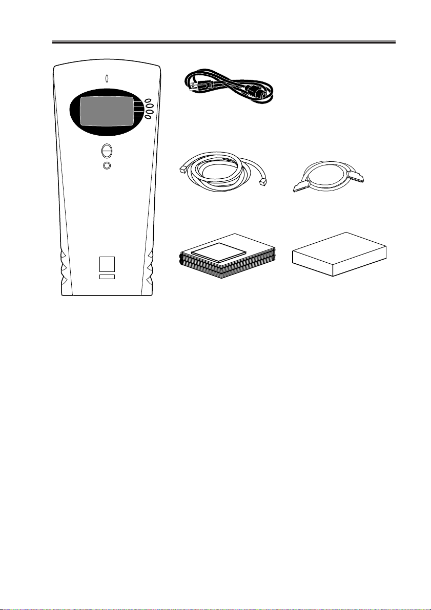
The iR-M1 is assembled and shipped from the factory in a box that includes all necessary
cables and documentation, as shown in F02-301-01 on page 2-7.
3.1 To Unpack the iR-M1
1. Open the box and remove any packing materials.
Save the original boxes and packing materials. If you need to transport the iR-M1 at a
later date, the original box and packing material will ensure safe shipment.
2. Remove the contents from the top container. Inspect the contents for visible damage.
The contents should include the following items:
• Bags containing the power cable and copier interface cable.
• iR-M1 media package (includes the user documentation).
3. Give the media package to the customer or the network administrator.
Let the customer or network administrator know that in order to take full advantage of
the iR-M1, user software must be installed on all computers that will print to it.
4. Set aside the remaining components from the top container.
5. Remove the top container and any packing materials. Set aside the packing material in
case you need to reship the unit.
6. Carefully lift the iR-M1 out of the box.
If you notice shipping damage to any iR-M1 component, be sure to save the shipping
container in case the carrier needs to see it. Call the carrier immediately to report the
damage and file a claim, then call your authorized service/support center. Be ready to
furnish the serial number, printed on the bottom of the chassis.
2-6
COPYRIGHT
©
2001 CANON INC. 2000 2000 2000 2000 NM-PDL REV.0 JULY 2001
CHAPTER 2 PREPARING FOR INSTALLATION
Power cable
Copier interface cable
(Cross Ethernet cable)
Media package
iR-M1
F02-301-01 Contents of the iR-M1 shipping box
Parallel cable
Network Interface Adapter
COPYRIGHT
©
2001 CANON INC. 2000 2000 2000 2000 NM-PDL REV.0 JULY 2001
2-7
CHAPTER 2 PREPARING FOR INSTALLATION
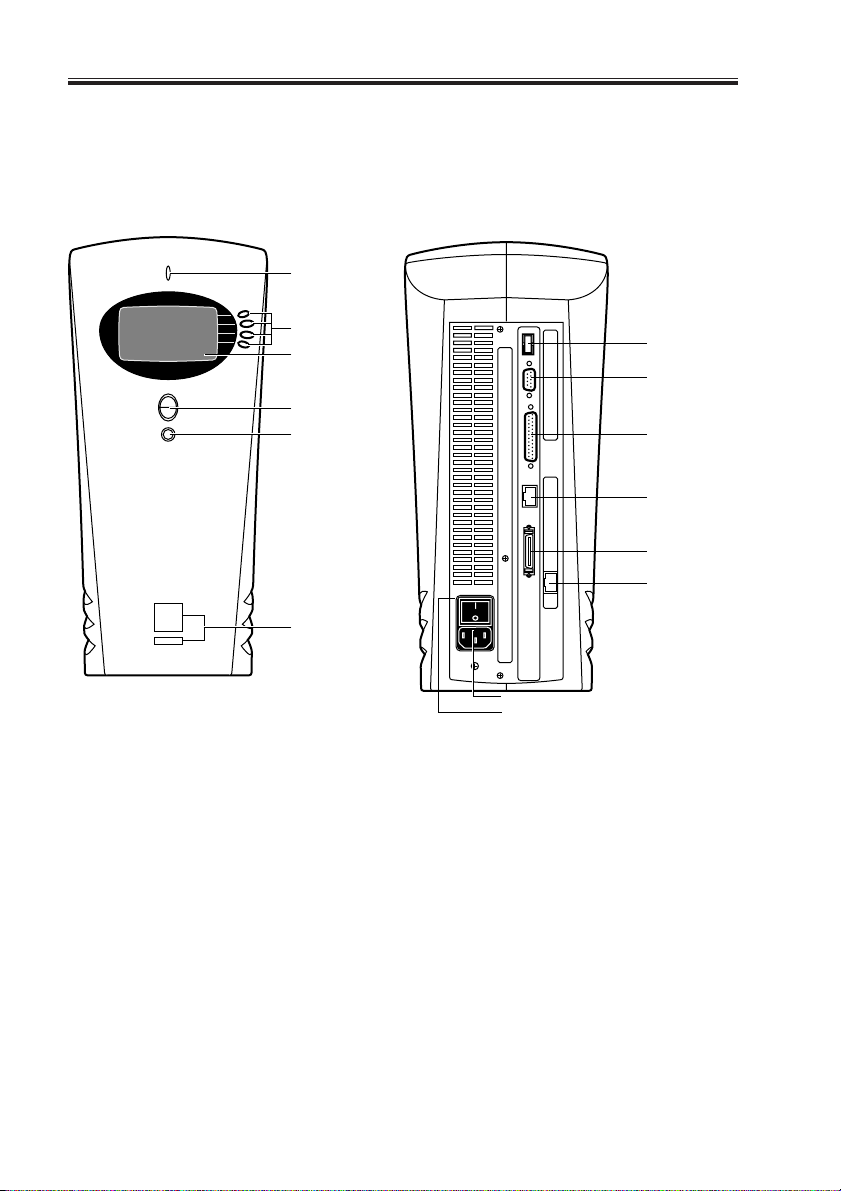
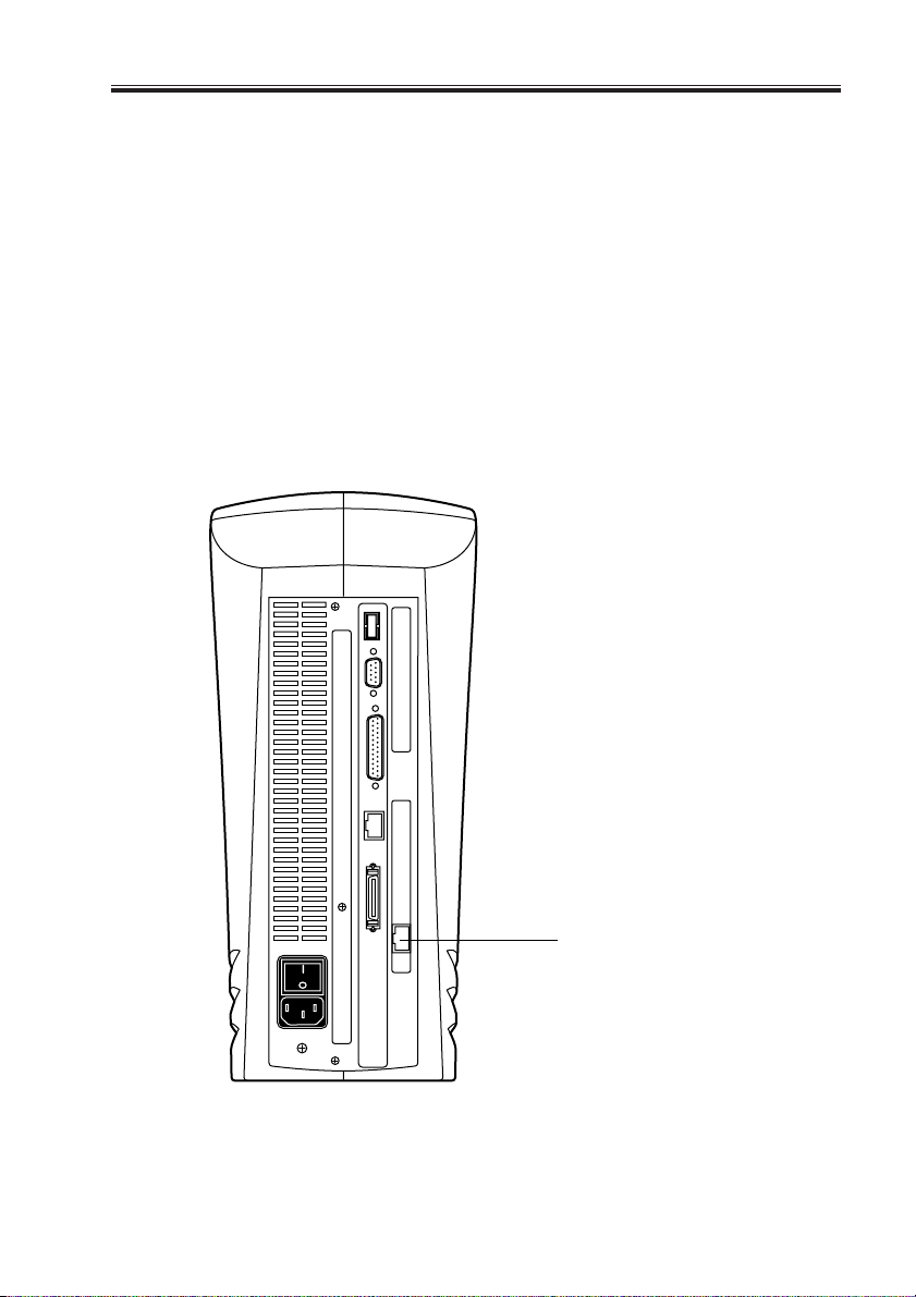
3.2 iR-M1 Panels
Once you have unpacked the iR-M1, you can familiarize yourself with the front and back
of the iR-M1 before you install it.
Front Back
Activity light
Line selection
buttons
Display window
Up and down
button
Menu button
Jewels
Not used
Not used
Not used
RJ-45 port
network
connection
Parallel port
Copier interface
port
2-8
Power connector
Power switch
F02-302-01 Front and back panels
COPYRIGHT
©
2001 CANON INC. 2000 2000 2000 2000 NM-PDL REV.0 JULY 2001

CHAPTER 3
INSTALLATION
COPYRIGHT
©
2001 CANON INC. 2000 2000 2000 2000 NM-PDL REV.0 JULY 2001
CHAPTER 3 INSTALLATION
1 Installation
This chapter includes the following information:
• Connecting power and checking out the iR-M1 (see below)
• Connecting the iR-M1 to the copier (page 3-3)
• Printing the Test Pages (page 3-4)
• Connecting to the network (page 3-5)
• Connecting a PC to the parallel port (page 3-7)
• Shutting down and restarting the iR-M1 (page 3-15)
This chapter also includes information on Control Panel screens and icons.
1.1 Preliminary Checkout
When you have just unpacked or serviced a iR-M1, power it on before you connect it to
the copier and the network. Diagnostics are run automatically during startup; the iR-M1 is
checked for internal problems.
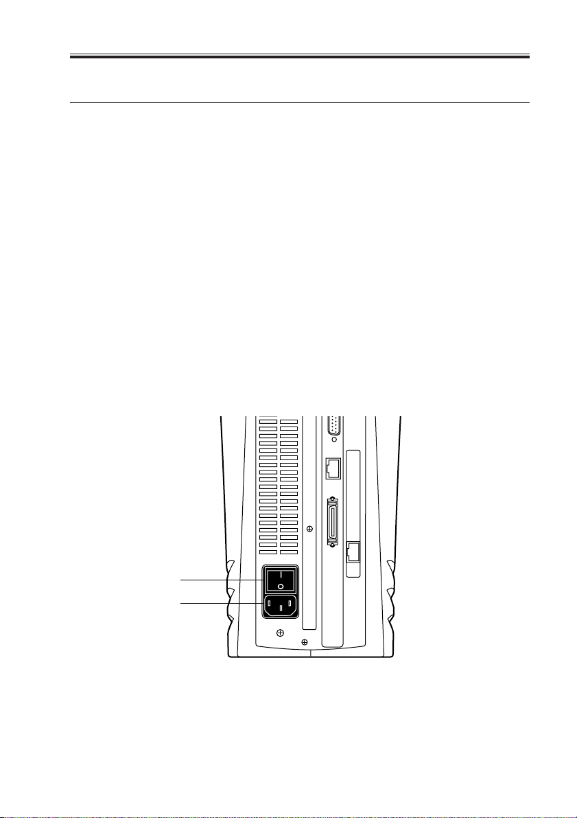
1.1.1 To Connect Power and Start the iR-M1
1. Connect the recessed end of the iR-M1 power cable to the power connector on the back
panel of the iR-M1.
2. Make sure that the iR-M1 power switch is in the Off position (press O), and plug the
other end of the power cable into a wall outlet.
Power switch
Power connector
COPYRIGHT
©
F03-101-01 Connecting the power cable
2001 CANON INC. 2000 2000 2000 2000 NM-PDL REV.0 JULY 2001
3-1

CHAPTER 3 INSTALLATION
3. Power on the iR-M1 using the switch at the back of the iR-M1. The power supply automatically senses the correct voltage.
4. To confirm that the iR-M1 is operating properly allow iR-M1 startup to proceed without
interruption while you watch the Control Panel. Do not press any buttons on the Control
Panel.
5. If the Select Language screen is displayed, select the language for the Control Panel.
The language screen is displayed the first time you start the iR-M1 after unpacking it.
Once you select the language the system reboots and beings initializing the system in
that language.
To select a language different from the one initially highlighted on the Control Panel,
use the up and down buttons to scroll through the list and select OK when the desired
language is highlighted.
6. Allow the system to proceed to Idle to confirm that the iR-M1 is operating correctly.
Once the iR-M1 reaches the idle state, you are ready to connect it to the copier and the
network. Setup options should be configured after making these connections. It is the
network administrator’s responsibility to configure Setup according to the network and
user environment. Refer the network administrator to the Configuration Guide for Setup
information.
Server Name
Idle
1047MB X.0
Info
3-2
F03-101-02
COPYRIGHT
©
2001 CANON INC. 2000 2000 2000 2000 NM-PDL REV.0 JULY 2001
CHAPTER 3 INSTALLATION
1.2 Connecting to the Copier
After successfully starting the iR-M1 by itself, you are ready to connect the iR-M1 to the
copier. The iR-M1 communicates with the copier through the copier interface cable.
1.2.1 To Connect the iR-M1 to the Copier
Before connect the iR-M1 to the copier, install the Ethernee Network Interface Adapter to
the copier.
1. Power off the iR-M1 as described on page 3-15.
2. Power on the copier and set ‘1’ to COPIER > OPTION > INT-FACE > IMG-CONT in
Service Mode.
3. Power off the copier.
4. Locate the copier interface cable. Connect one end of the cable to the iR-M1 interface
port on the copier.
5. Connect the other end of the copier interface cable to the iR-M1 copier interface port.
COPYRIGHT
©
Copier interface port
F03-102-01 iR-M1 copier interface port connection
2001 CANON INC. 2000 2000 2000 2000 NM-PDL REV.0 JULY 2001
3-3

CHAPTER 3 INSTALLATION
1.3 Verifying the Connection
After you connect the iR-M1 to the copier, print the Test Page to verify that the connec-
tion between the iR-M1 and the copier is good.
1.3.1 Printing the iR-M1 Test Pages
Before connecting the iR-M1 to the network, print the Test Pages to verify that it is connected properly to the copier. The PS and PCL Test Pages are PostScript files that reside on
the iR-M1 hard disk drive. Print both pages to make sure the connection is operating.
a. To Print the Test Page from the Control Panel
1. Power on the copier and allow it to warm up.
2. Power on the iR-M1 using the power switch on the back panel.
Messages will appear on the Control Panel as the iR-M1 runs through its Start-up diagnostics.
3. Before proceeding, make sure that the copier is not in use.
4. At the Idle screen, press the menu button (see “Using the Control Panel” on page 3-9).
The Functions menu displays.
Print Pages
Select
Suspend Printing
Resume Printing
Reboot Server
Functions
Run Setup
Run Diagnostics
Functions
F03-103-01
5. Press the line selection button to the right of Print Pages and then select PS Test Page.
The iR-M1 sends the PS Test Page to the copier and displays the RIP and Print status
screens so you can monitor the job.
6. Press the line selection button to the right of Print Pages again and then select PCL Test
Page.
The iR-M1 sends the PCL Test Page to the copier and displays the RIP and Print status
screens so you can monitor the job.
7. Examine the quality of the Test Pages from the copier.
3-4
COPYRIGHT
©
2001 CANON INC. 2000 2000 2000 2000 NM-PDL REV.0 JULY 2001
 Loading...