

Canon imageRUNNER iR2270, imageRUNNER iR2870, imageRUNNER iR3570, imageRUNNER iR4570, Finisher-S1 Service Manual
SERVICE
MANUAL
imageRUNNER
COPYRIGHT 2004 CANON INC. CANON imageRUNNER Finisher-S1 REV. 0 PRINTED IN U.S.A.
DU7-1130-000
SEPT. 2004
REV. 0
iR2270/2870/
3570/4570
Finisher-S1

Application
This manual has been issued by Canon Inc. for qualified persons to learn technical theory, installation,
maintenance, and repair of products. This manual covers all localities where the products are sold. For
this reason, there may be information in this manual that does not apply to your locality.
Corrections
This manual may contain technical inaccuracies or typographical errors due to improvements or changes
in products. When changes occur in applicable products or in the contents of this manual, Canon will
release technical information as the need arises. In the event of major changes in the contents of this
manual over a long or short period, Canon will issue a new edition of this manual.
The following paragraph does not apply to any countries where such provisions are inconsistent with
local law.
Trademarks
The product names and company names used in this manual are the registered trademarks of the
individual companies.
Copyright
This manual is copyrighted with all rights reserved. Under the copyright laws, this manual may not be
copied, reproduced or translated into another language, in whole or in part, without the written consent
of Canon Inc.
COPYRIGHT © 2001 CANON INC.
Printed in Japan
Caution
Use of this manual should be strictly supervised to avoid disclosure of confidential information.

Introduction
Symbols Used
This documentation uses the following symbols to indicate special information:
Symbol Description
Indicates an item of a non-specific nature, possibly classified as Note,
Caution, or Warning.
Indicates an item requiring care to avoid electric shocks.
Indicates an item requiring care to avoid combustion (fire).
Indicates an item prohibiting disassembly to avoid electric shocks or
problems.
Indicates an item requiring disconnection of the power plug from the electric
outlet.
Memo
REF.
Indicates an item intended to provide notes assisting the understanding of the
topic in question.
Indicates an item of reference assisting the understanding of the topic in
question.
Provides a description of a service mode.
Provides a description of the nature of an error indication.

Introduction
The following rules apply throughout this Service Manual:
1. Each chapter contains sections explaining the purpose of specific functions and the
relationship between electrical and mechanical systems with reference to the timing of
operation.
In the diagrams, represents the path of mechanical drive; where a signal name
accompanies the symbol, the arrow indicates the direction of the electric
signal.
The expression "turn on the power" means flipping on the power switch, closing the front
door, and closing the delivery unit door, which results in supplying the machine with
power.
2. In the digital circuits, '1'is used to indicate that the voltage level of a given signal is
"High", while '0' is used to indicate "Low".(The voltage value, however, differs from
circuit to circuit.) In addition, the asterisk (*) as in "DRMD*" indicates that the DRMD
signal goes on when '0'.
In practically all cases, the internal mechanisms of a microprocessor cannot be checked
in the field. Therefore, the operations of the microprocessors used in the machines are
not discussed: they are explained in terms of from sensors to the input of the DC
controller PCB and from the output of the DC controller PCB to the loads.
The descriptions in this Service Manual are subject to change without notice for product
improvement or other purposes, and major changes will be communicated in the form of
Service Information bulletins.
All service persons are expected to have a good understanding of the contents of this
Service Manual and all relevant Service Information bulletins and be able to identify and
isolate faults in the machine."

Contents
Contents
Chapter 1 Specifications
1.1 Product Specifications ............................................................................................... 1-1
1.1.1 Specifications ...................................................................................................... 1-1
1.2 Names of Parts ........................................................................................................... 1-6
1.2.1 External View ..................................................................................................... 1-6
1.2.2 Cross-sectional View .......................................................................................... 1-7
Chapter 2 Functions
2.1 Basic Construction ..................................................................................................... 2-1
2.1.1 Overview ............................................................................................................. 2-1
2.1.2 Outline of Electric Circuits ................................................................................. 2-2
2.2 Basic Operation.......................................................................................................... 2-3
2.2.1 Basic Operation................................................................................................... 2-3
2.3 Feed Drive System..................................................................................................... 2-8
2.3.1 Overview ............................................................................................................. 2-8
2.3.2 Feed Roller Control............................................................................................. 2-9
2.3.3 Offset Roller Control ........................................................................................ 2-10
2.3.4 Feed Motor Control........................................................................................... 2-14
2.3.5 Offset Motor Control ........................................................................................ 2-15
2.4 Staple Operation ...................................................................................................... 2-16
2.4.1 Functional Configuration .................................................................................. 2-16
2.4.2 Staple Motor Control ........................................................................................ 2-18
2.5 Stack Tray Operation ............................................................................................... 2-19
2.5.1 Overview ........................................................................................................... 2-19
2.5.2 Stack Ejection ................................................................................................... 2-20
2.5.3 Stack Slide Motor Control ................................................................................ 2-22
2.5.4 Stack Tray Shift Motor Control ........................................................................ 2-23
2.6 Detecting Jams ......................................................................................................... 2-24
2.6.1 Overview ........................................................................................................... 2-24
2.7 Power Supply........................................................................................................... 2-26
2.7.1 Overview ........................................................................................................... 2-26
2.7.2 Protection Function ........................................................................................... 2-26

Contents
Chapter 3 Parts Replacement Procedure
3.1 External Covers.......................................................................................................... 3-1
3.1.1 Upper Cover ........................................................................................................3-1
3.1.1.1 Removing the PCB Cover ............................................................................ 3-1
3.1.1.2 Removing the Top Harness Cover ............................................................... 3-1
3.1.1.3 Removing the Upper Cover.......................................................................... 3-2
3.1.2 Left Cover ........................................................................................................... 3-2
3.1.2.1 Removing the Left Cover ............................................................................. 3-2
3.1.3 PCB Cover .......................................................................................................... 3-3
3.1.3.1 Removing the PCB Cover ............................................................................ 3-3
3.1.4 Top Harness Cover ..............................................................................................3-3
3.1.4.1 Removing the PCB Cover ............................................................................ 3-3
3.1.4.2 Removing the Top Harness Cover ............................................................... 3-4
3.1.5 Bottom Cover ......................................................................................................3-4
3.1.5.1 Removing the Bottom Cover........................................................................ 3-4
3.1.6 Tray Guide Top Cover ........................................................................................ 3-5
3.1.6.1 Removing the Bottom Cover........................................................................ 3-5
3.1.6.2 Removing the Tray Guide Top Cover .......................................................... 3-6
3.2 Drive System.............................................................................................................. 3-7
3.2.1 Feed Motor ..........................................................................................................3-7
3.2.1.1 Removing the PCB Cover ............................................................................ 3-7
3.2.1.2 Removing the Top Harness Cover ............................................................... 3-7
3.2.1.3 Removing the Upper Cover.......................................................................... 3-8
3.2.1.4 Removing the Stapler Cover ........................................................................ 3-8
3.2.1.5 Removing the Drive Unit ............................................................................. 3-9
3.2.1.6 Removing the Process Tray Unit.................................................................. 3-9
3.2.1.7 Removing the Feed Motor.......................................................................... 3-10
3.2.2 Stack Tray Shift Motor ......................................................................................3-10
3.2.2.1 Removing the PCB Cover .......................................................................... 3-10
3.2.2.2 Removing the Top Harness Cover ............................................................. 3-11
3.2.2.3 Removing the Upper Cover........................................................................ 3-11
3.2.2.4 Removing the Bottom Cover...................................................................... 3-12
3.2.2.5 Removing the Left Cover ........................................................................... 3-12
3.2.3 Stapler ...............................................................................................................3-13
3.2.3.1 Removing the PCB Cover .......................................................................... 3-13
3.2.3.2 Removing the Top Harness Cover ............................................................. 3-13
3.2.3.3 Removing the Upper Cover........................................................................ 3-14
3.2.3.4 Removing the Stapler Cover ...................................................................... 3-15
3.2.3.5 Removing the Stapler ................................................................................. 3-15

Contents
3.2.4 Drive Unit ......................................................................................................... 3-15
3.2.4.1 Removing the PCB Cover .......................................................................... 3-15
3.2.4.2 Removing the Top Harness Cover ............................................................. 3-16
3.2.4.3 Removing the Upper Cover........................................................................ 3-16
3.2.4.4 Removing the Stapler Cover ...................................................................... 3-17
3.2.4.5 Removing the Drive Unit ........................................................................... 3-17
3.2.5 Offset Motor ...................................................................................................... 3-18
3.2.5.1 Removing the PCB Cover .......................................................................... 3-18
3.2.5.2 Removing the Top Harness Cover ............................................................. 3-19
3.2.5.3 Removing the Upper Cover........................................................................ 3-19
3.2.5.4 Removing the Offset Motor ....................................................................... 3-20
3.2.6 Stack Slide Motor .............................................................................................. 3-20
3.2.6.1 Removing the PCB Cover .......................................................................... 3-20
3.2.6.2 Removing the Top Harness Cover ............................................................. 3-21
3.2.6.3 Removing the Upper Cover........................................................................ 3-21
3.2.6.4 Removing the Stapler Cover ...................................................................... 3-22
3.2.6.5 Removing the Drive Unit ........................................................................... 3-22
3.2.6.6 Removing the Process Tray Unit ............................................................... 3-23
3.2.6.7 Removing the Stack Slide Motor ............................................................... 3-24
3.3 Document Feeding System ...................................................................................... 3-25
3.3.1 Stack Tray Assembly ........................................................................................ 3-25
3.3.1.1 Removing the PCB Cover .......................................................................... 3-25
3.3.1.2 Removing the Top Harness Cover ............................................................. 3-25
3.3.1.3 Removing the Upper Cover........................................................................ 3-26
3.3.1.4 Removing the Bottom Cover...................................................................... 3-26
3.3.1.5 Removing the Left Cover ........................................................................... 3-27
3.3.1.6 Removing the Tray Guide Top Cover ........................................................ 3-27
3.3.1.7 Removing the Stapler Cover ...................................................................... 3-28
3.3.1.8 Removing the Stack Tray Assembly .......................................................... 3-28
3.3.2 Process Tray Assembly ..................................................................................... 3-28
3.3.2.1 Removing the PCB Cover .......................................................................... 3-28
3.3.2.2 Removing the Top Harness Cover ............................................................. 3-29
3.3.2.3 Removing the Upper Cover........................................................................ 3-29
3.3.2.4 Removing the Stapler Cover ...................................................................... 3-30
3.3.2.5 Removing the Drive Unit ........................................................................... 3-30
3.3.2.6 Removing the Process Tray Unit ............................................................... 3-31
3.3.3 Feed Rollor ........................................................................................................ 3-32
3.3.3.1 Removing the PCB Cover .......................................................................... 3-32
3.3.3.2 Removing the Top Harness Cover ............................................................. 3-32
3.3.3.3 Removing the Upper Cover........................................................................ 3-33

Contents
3.3.3.4 Removing the Feed Roller.......................................................................... 3-33
3.4 Electrical System ..................................................................................................... 3-35
3.4.1 Stack Tray Paper Surface Sensor ......................................................................3-35
3.4.1.1 Removing the PCB Cover .......................................................................... 3-35
3.4.1.2 Removing the Top Harness Cover ............................................................. 3-35
3.4.1.3 Removing the Upper Cover........................................................................ 3-36
3.4.1.4 Removing the Stapler Cover ...................................................................... 3-36
3.4.1.5 Removing the Stapler ................................................................................. 3-37
3.4.1.6 Removing the Drive Unit ........................................................................... 3-37
3.4.1.7 Removing the Process Tray Unit................................................................ 3-38
3.4.1.8 Removing the Stack Tray Paper Surface Sensor ........................................ 3-38
3.4.2 Stack Tray Lower Limit Sensor ........................................................................ 3-39
3.4.2.1 Removing the Stack Tray Lower Limit Sensor .......................................... 3-39
3.4.3 Process Tray Paper Sensor ................................................................................ 3-39
3.4.3.1 Removing the PCB Cover .......................................................................... 3-39
3.4.3.2 Removing the Top Harness Cover ............................................................. 3-40
3.4.3.3 Removing the Upper Cover........................................................................ 3-40
3.4.3.4 Removing the Stapler Cover ...................................................................... 3-41
3.4.3.5 Removing the Drive Unit ........................................................................... 3-41
3.4.3.6 Removing the Process Tray Unit................................................................ 3-42
3.4.3.7 Removing the Process Tray Paper Sensor .................................................. 3-43
3.4.4 Finisher Controller PCB ....................................................................................3-43
3.4.4.1 Finisher Controller PCB ............................................................................. 3-43
3.4.5 Front Cover Safety Switch ................................................................................ 3-45
3.4.5.1 Removing the PCB Cover .......................................................................... 3-45
3.4.5.2 Removing the Front Door Safety Switch ................................................... 3-45
3.4.6 Inlet Sensor ........................................................................................................3-45
3.4.6.1 Removing the PCB Cover .......................................................................... 3-45
3.4.6.2 Removing the Top Harness Cover ............................................................. 3-46
3.4.6.3 Removing the Upper Cover........................................................................ 3-46
3.4.6.4 Removing the Inlet Sensor ......................................................................... 3-47
3.4.7 Stack Slide HP Sensor ....................................................................................... 3-48
3.4.7.1 Removing the PCB Cover .......................................................................... 3-48
3.4.7.2 Removing the Top Harness Cover ............................................................. 3-48
3.4.7.3 Removing the Upper Cover........................................................................ 3-48
3.4.7.4 Removing the Stapler Cover ...................................................................... 3-49
3.4.7.5 Removing the Drive Unit ........................................................................... 3-49
3.4.7.6 Removing the Process Tray Unit................................................................ 3-50
3.4.7.7 Stack Slide HP Sensor ................................................................................ 3-51
3.4.8 Offset HP Sensor ............................................................................................... 3-51

Contents
3.4.8.1 Removing the PCB Cover .......................................................................... 3-51
3.4.8.2 Removing the Top Harness Cover ............................................................. 3-51
3.4.8.3 Removing the Upper Cover........................................................................ 3-52
3.4.8.4 Removing the Offset HP Sensor ................................................................ 3-53
3.4.9 Tray Clock Sensor ............................................................................................. 3-53
3.4.9.1 Removing the PCB Cover .......................................................................... 3-53
3.4.9.2 Removing the Top Harness Cover ............................................................. 3-54
3.4.9.3 Removing the Upper Cover........................................................................ 3-54
3.4.9.4 Removing the Bottom Cover...................................................................... 3-55
3.4.9.5 Removing the left cover ............................................................................. 3-56
3.4.9.6 Removing the Tray Guide Top Cover ........................................................ 3-56
3.4.9.7 Removing the Stack Tray Assembly .......................................................... 3-57
3.4.9.8 Removing the Tray Clock Sensor .............................................................. 3-57
3.4.10 Offset Solenoid ............................................................................................... 3-58
3.4.10.1 Removing the PCB Cover ........................................................................ 3-58
3.4.10.2 Removing the Top Harness Cover ........................................................... 3-58
3.4.10.3 Removing the Upper Cover...................................................................... 3-58
3.4.10.4 Removing the Offset Solenoid ................................................................. 3-59
3.4.11 Paper Holder Solenoid .................................................................................... 3-60
3.4.11.1 Removing the PCB Cover ........................................................................ 3-60
3.4.11.2 Removing the Top Harness Cover ........................................................... 3-60
3.4.11.3 Removing the Upper Cover...................................................................... 3-60
3.4.11.4 Removing the Stapler Cover .................................................................... 3-61
3.4.11.5 Removing the Stapler ............................................................................... 3-61
3.4.11.6 Removing the Drive Unit ......................................................................... 3-62
3.4.11.7 Removing the Process Tray Unit ............................................................. 3-62
3.4.11.8 Removing the Paper Holder Solenoid ...................................................... 3-63
Chapter 4 Maintenance
4.1 Maintenance and Inspection ...................................................................................... 4-1
4.1.1 Periodically Replaced Parts ................................................................................ 4-1
4.1.1.1 Periodically Replaced Parts.......................................................................... 4-1
4.1.2 Durables .............................................................................................................. 4-1
4.1.2.1 Durables ....................................................................................................... 4-1
4.1.3 Periodical Servicing ............................................................................................ 4-2
4.1.3.1 Periodical Servicing ..................................................................................... 4-2
4.2 Adjustment................................................................................................................. 4-3
4.2.1 Adjustment at Time of Parts Replacement ......................................................... 4-3

Contents
4.2.1.1 Making Adjustments When Replacing the Finisher Controller PCB........... 4-3
4.3 Outline of Electrical Components.............................................................................. 4-4
4.3.1 Outline of Electrical Components....................................................................... 4-4
4.4 Variable Resistors (VR), Light-Emitting Diodes (LED), and Check Pins by PCB... 4-7
4.4.1 Light-Emitting Diodes and Check Pins by PCB ................................................. 4-7
4.4.2 Finisher Controller PCB...................................................................................... 4-8
4.4.3 DIP Switch Functions ......................................................................................... 4-9
Chapter 5 Error Code
5.1 Service Error Code..................................................................................................... 5-1
5.1.1 Service Error Code .............................................................................................. 5-1

Chapter 1
Specifications

Contents
Contents
1.1 Product Specifications................................................................................1-1
1.1.1 Specifications ...................................................................................... 1-1
1.2 Names of Parts ...........................................................................................1-6
1.2.1 External View......................................................................................1-6
1.2.2 Cross-sectional View ..........................................................................1-7
1.1 Product Specifications
Chapter 1
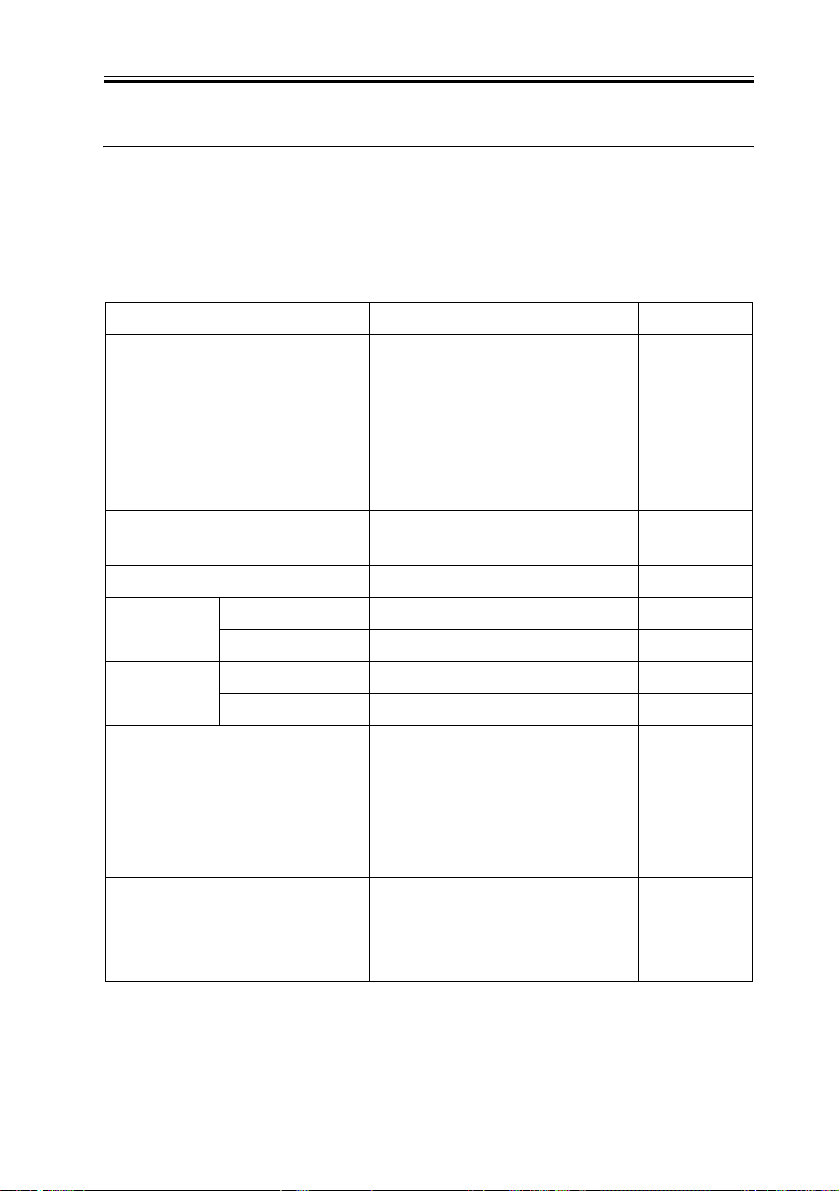
1.1.1 Specifications
T-1-1
Item Description Remarks
Stack tray 1-stage tray and extension tray for large size
paper
Stacking method Lowering stack tray
(1-bin self-running)
Loading method Face-down
Loading paper
size
Paper weight
Paper size A3, B4, A4, A4R, B5, B5R, A5R, postcard,
Media type Plain paper, recycled paper, colored paper,
Longitudinal 139.7 mm to 457 mm
Lateral 98.4 mm to 320 mm
Staple loading 64g/m2 to 80g/m2
Non-staple loading 64g/m2 to 128g/m2
double postal card, 4-leaf postcard, irregular
sizes (182 x 140 mm to 297 x 432 mm),
envelope (105 mm x 235 mm, COM10,
Monarch, DL, ISO-B5, ISO-C5)
64g/m2 to 128g/m2
punched paper, thick paper, secondary
original drawing, transparency, label sheet,
postcard, double postal card, 4-leaf postcard
0006-1918
Two-bin
configuration can
be used by
attaching
additional
finisher tray
(B1).
1-1

Chapter 1
Item Description Remarks
Staple loading A3,A4,A4R,B4,B5,LDR,LGL,LTR,LTRR
Non-staple loading A3,A4,A4R,A5,A5R,B4,B5,B5R,LDR,LGL,
LTR,LTRR, postcard, envelope
Modes
Stack offset loading A3,A4,A4R,B4,B5,LDR,LGL,LTR,LTRR - Shift amount:
43.5 to 87 mm
- Shiftable width:
210 mm to 297
mm
1-2
Number of
loadable sheets
Alignment range
Chapter 1
Item Description Remarks
Standard tray Non-sort, sort, group
A4, B5, A5R: 1000 sheets (height = 130 mm)
A3, B4, A4R, B5R: 500 sheets (height = 65
mm)
Staple sort
A4, B5: 1000 sheets/30 copies (height = 130
mm)
Non-sort, sort, group (Mixed size): 500
sheets (height = 65 mm)
Staple sort (Mixed size): 500 sheets/30 copies
(height = 65 mm)
Optional tray Non-sort, soft, group
A4, B5, A5R: 300 sheets (height = 40 mm)
A3, B4, A4R, B5R: 150 sheets (height = 20
mm)
Staple sort
A4, B5: 300 sheets/30 copies (height = 40
mm)
A3, B4, A4R: 150 sheets/30 copies (height =
20 mm)
Non-sort, sort, group (Mixed size):,150
sheets (height = 20 mm)
Staple sort (Mixed size): 150 sheets/30 copies
(height = 20 mm)
When optional tray is
installed
Staple stack A4, B4: 50 sheets (64 to 80 g/m2)
Staple loading Paper width: 210.0 mm to 297.0 mm
Non-staple loading Paper width: 210.0 mm to 297.0 mm
Stack offset loading Paper width: 210.0 mm to 297.0 mm
Upper tray
Small size: Height = 40 mm; Large size:
Height = 20 mm
Lower tray
Small size: Height = 40 mm; Large size:
Height = 20 mm
A3, B4, A4R: 30 sheets (64 to 80 g/m2)
80 g/m2 paper
1-3

Chapter 1
Paper detection Intermediate process
Number of mixed
sheets
Operation panel None
Display screen None
Installation type Built-in
Dimensions 480mm(W) x 520mm(D) x 300mm(H)
Weight 12kg
Power supply Powered from main body (24 V/13 V)
Max. power
consumption
Operating noise Main body + DF +
Options Additional finisher tray-B1
Item Description Remarks
Detected
tray
Stack tray Detected
Mixed size 65 mm or lower in height 20 mm when
Mixed staple 65 mm or lower in height or 30 or fewer
copies
Mixed mode 65 mm or lower in height or 30 or fewer
copies
Powered from main
body
Finisher
Approx. 45 W or less
Noise specification for main body + 3 dB (full
system)
Puncher unit-R1/S1/T1
additional
finisher tray (B1)
is installed
(loadability is not
quaranteed)
T-1-2
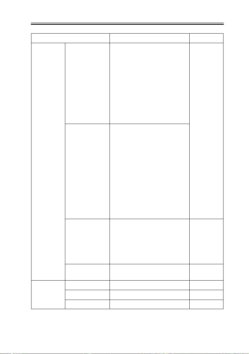
Item Description
Stapling method Stapling by rotary cam
Stapling position - Oblique stapling at one position
Number of sheets that can
be stapled
Staple loading method Replacement of dedicated staple sheet cartridge
Small size: 50 sheets; Large size: 30 sheets
Maximum: Two 128 g/m2 sheets + Forty-eight 80
g/m2 sheets (small size)
(5000 staples)
1-4
Remarks
A3,A4,A4R,B4,B5,LD
R,LGL,LTR,LTRR
Paper thickness: 5.5 mm
max.

No staple detection Detected
Manual stapling Disabled
Standby function Provided
- Stapling position (one position, rear)
5.0 2mm
45
5.0 2mm
A3 , B4 , A4 , A4R , B5 , LDR , LGL , LTR , LTR-R
F-1-1
Chapter 1
1-5
Chapter 1
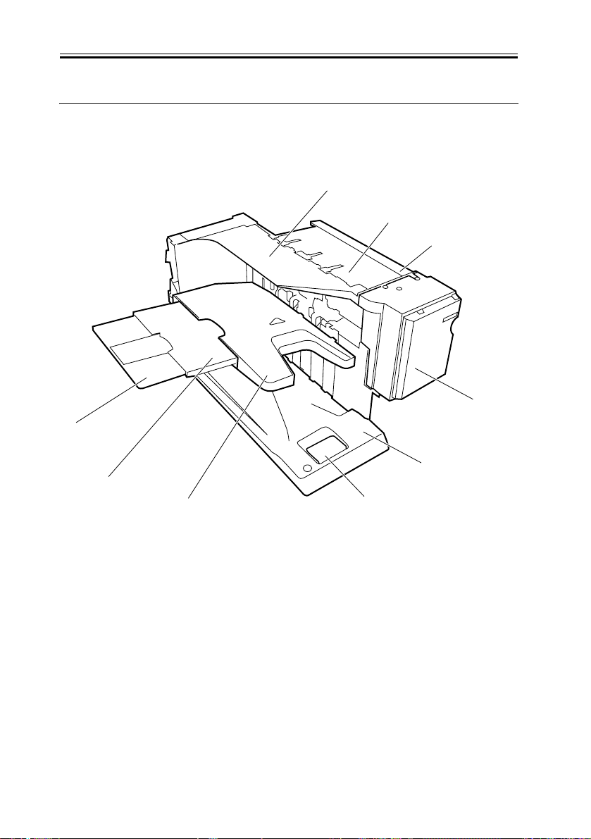
1.2 Names of Parts
1.2.1 External View
[9]
[8]
[7]
F-1-2
0006-1920
[1]
[2]
[3]
[4]
[5]
[6]
[1] Top harness cover
[2] Top cover
[3] Reversal guide
[4] PCB cover
[5] Bottom cover
[6] Pulling handle
[7] Stack tray
[8] Stack extension tray 1
[9] Stack extension tray 2
1-6
Chapter 1
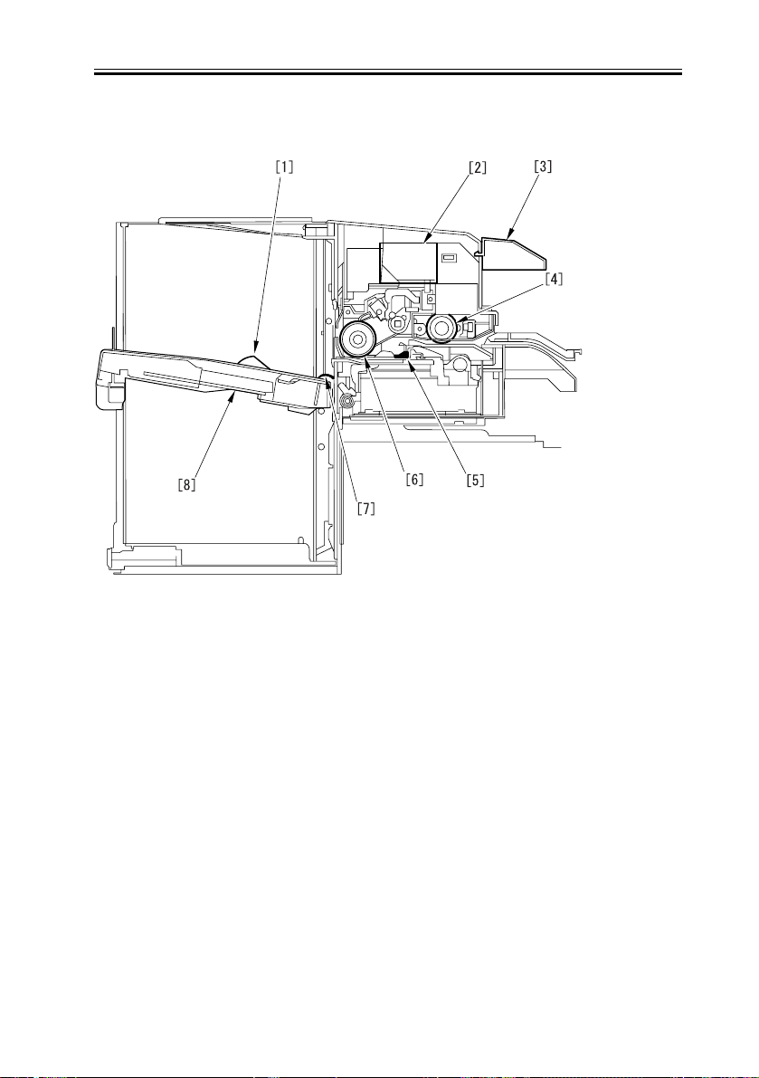
1.2.2 Cross-sectional View
F-1-3
0006-1922
[1] Stack tray paper presence sensor
[2] Stapler
[3] Reversal guide
[4] Feed roller
[5] Stack slider
[6] Offset roller
[7] Paper holder
[8] Stack tray
1-7

Chapter 2
Functions

Contents
Contents
2.1 Basic Construction .....................................................................................2-1
2.1.1 Overview .............................................................................................2-1
2.1.2 Outline of Electric Circuits ................................................................. 2-2
2.2 Basic Operation..........................................................................................2-3
2.2.1 Basic Operation...................................................................................2-3
2.3 Feed Drive System .....................................................................................2-8
2.3.1 Overview .............................................................................................2-8
2.3.2 Feed Roller Control.............................................................................2-9
2.3.3 Offset Roller Control.........................................................................2-10
2.3.4 Feed Motor Control...........................................................................2-14
2.3.5 Offset Motor Control.........................................................................2-15
2.4 Staple Operation.......................................................................................2-16
2.4.1 Functional Configuration ..................................................................2-16
2.4.2 Staple Motor Control.........................................................................2-18
2.5 Stack Tray Operation ...............................................................................2-19
2.5.1 Overview ...........................................................................................2-19
2.5.2 Stack Ejection....................................................................................2-20
2.5.3 Stack Slide Motor Control ................................................................2-22
2.5.4 Stack Tray Shift Motor Control ........................................................2-23
2.6 Detecting Jams ......................................................................................... 2-24
2.6.1 Overview ...........................................................................................2-24
2.7 Power Supply ........................................................................................... 2-26
2.7.1 Overview ...........................................................................................2-26
2.7.2 Protection Function ...........................................................................2-26
2.1 Basic Construction
Chapter 2
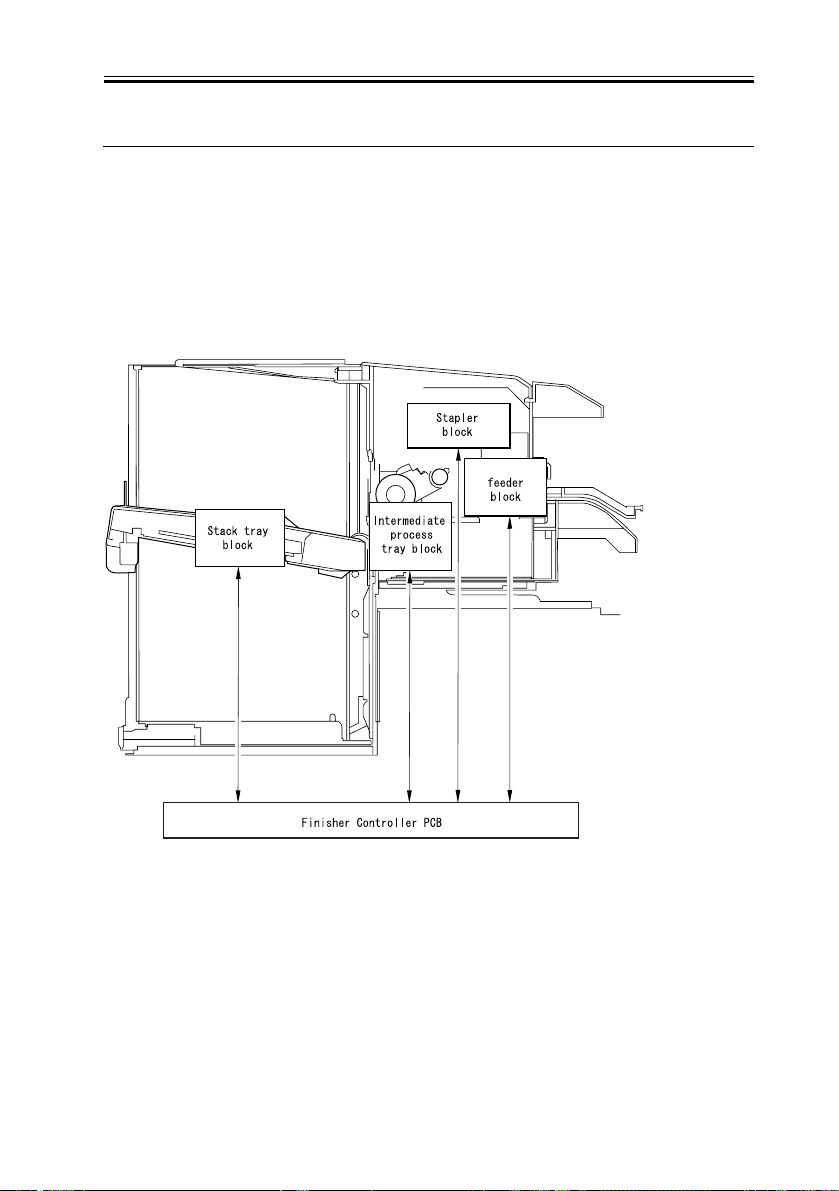
2.1.1 Overview
The finisher consists of four blocks: a stack tray, stapler, intermediate process tray, and
feeder blocks.
The following illustration shows locations of these four blocks and the finisher controller
PCB.
0006-1928
F-2-1
2-1
Chapter 2
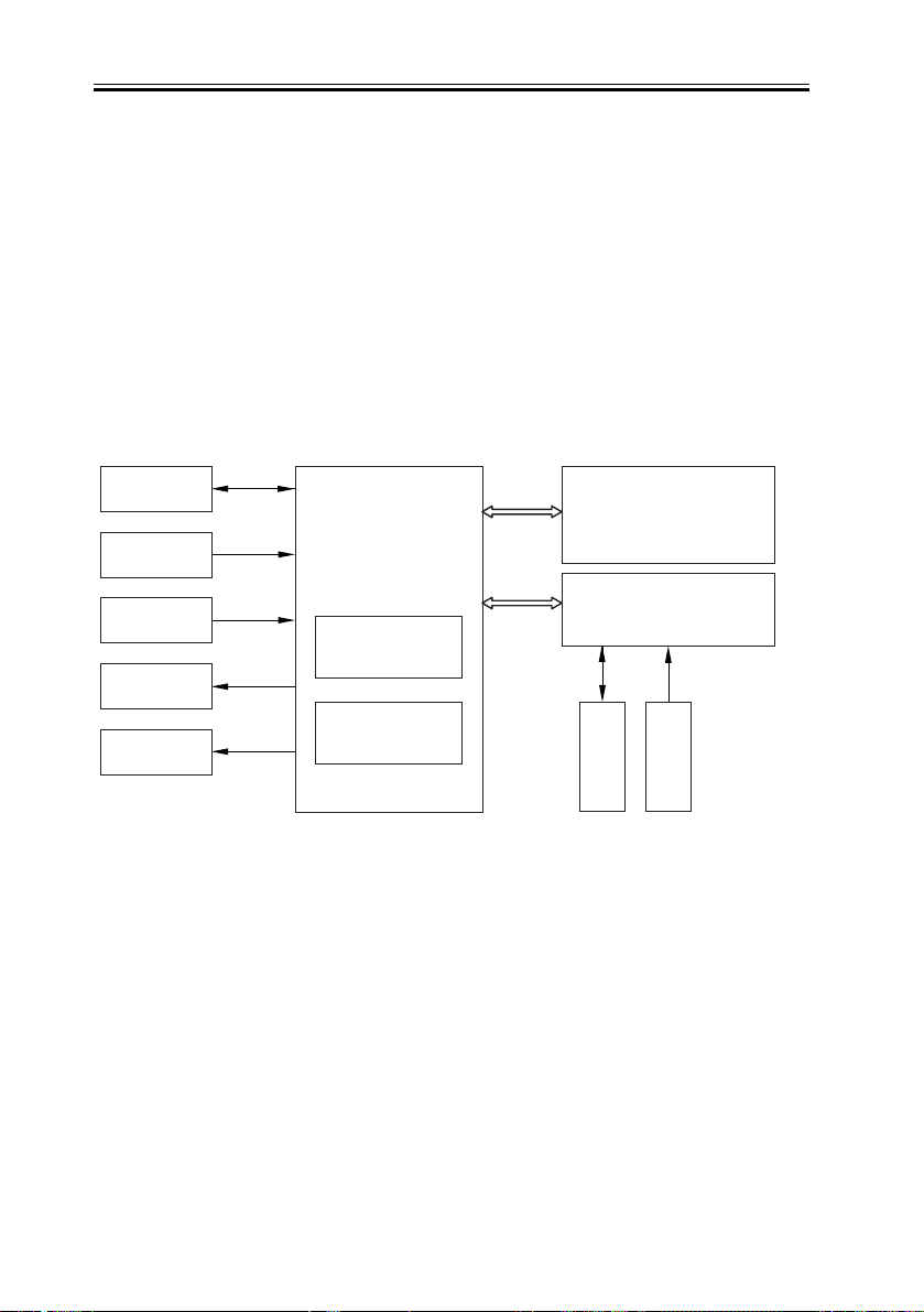
2.1.2 Outline of Electric Circuits
0006-1929
The operation sequence of the finisher is controlled by the finisher controller PCB.
The finisher controller PCB incorporates a 16-bit CPU to perform sequence control (and
serial communication with the host machine).
The CPU on the finisher controller PCB incorporates a ROM that stores an operation
sequence program.
The finisher controller PCB drives motors in response to the commands sent from the host
machine via a serial communication line.
The finisher controller PCB also sends information about various sensors and switches to
the host machine via the serial communication line.
Motor
Sensor
Switch
Solenoid
Clutch*1
Finisher controller
PCB
CPU
Motor driver
Host machine
(DC controller PCB
with CPU)
Option tray PCB*1
Motor*1
Sensor*1
*1: Only when option tray is installed
F-2-2
2-2
2.2 Basic Operation
Chapter 2
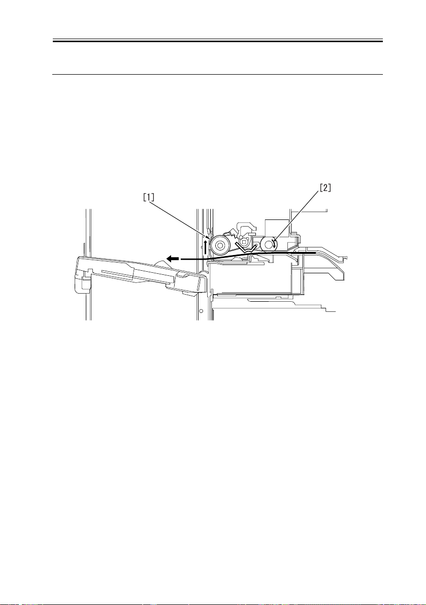
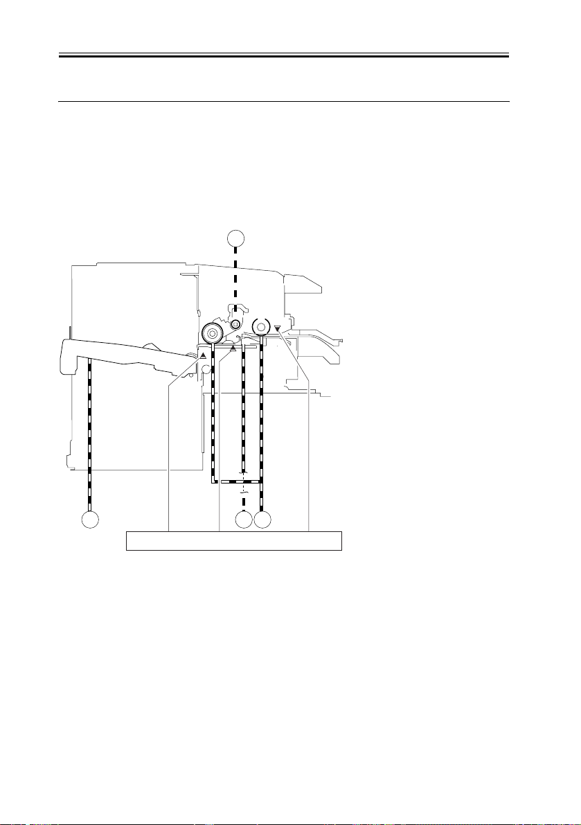
2.2.1 Basic Operation
- Ejection of 3-sheet stack (after offsetting and stapling)
1) The offset roller [1] rises.
2) Paper is fed only with the feed roller [2]. (The offset roller and feed roller are driven
together.)
F-2-3
3) The offset roller [3] lowers to feed paper together with the feed roller [4].
4) After passing through the feed roller [4], paper is fed only with the offset roller [3] and
then it stops on the process tray.
0006-1931
2-3
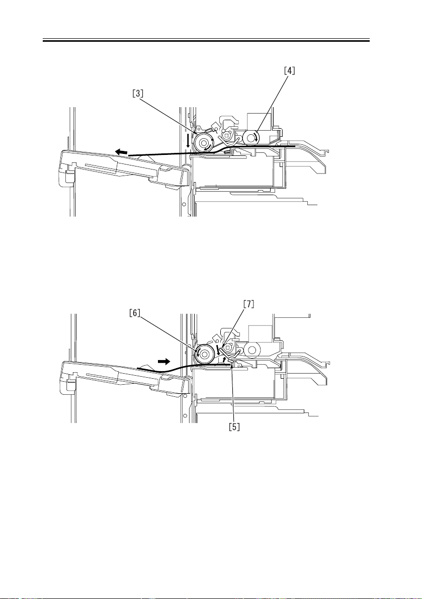
Chapter 2
F-2-4
5) The paper holder [5] opens.
6) The offset roller [6] turns reversely to push the paper against the restriction plate.
7) The anti-curl plate [7] blocks the path with the rotation of the feed roller.
F-2-5
8) The offset roller [8] is brought into contact with the upper surface of the paper to offset
the paper. Next, the paper is pushed against the rear restriction plate for alignment.
9) The offset roller [8] is raised to close the paper holder.
2-4
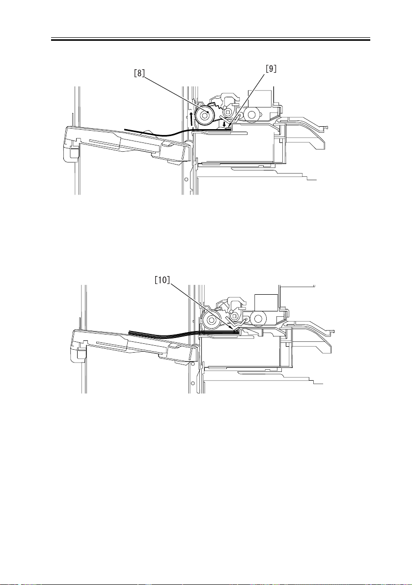
Chapter 2
F-2-6
10) Steps 2 to 10 are repeated to put the succeeding sheet in the process tray.
11) After completion of alignment or stapling, the paper holder [10] catches hold of the
paper stack.
F-2-7
12) With the paper stack held by the paper holder, the stack slider [11] moves toward the
stack tray and stops.
13) The return wall [12] is pressed by the stack slider, being raised on the process tray.
14) The tray paper holder [13] moves away from the stack tray.
2-5
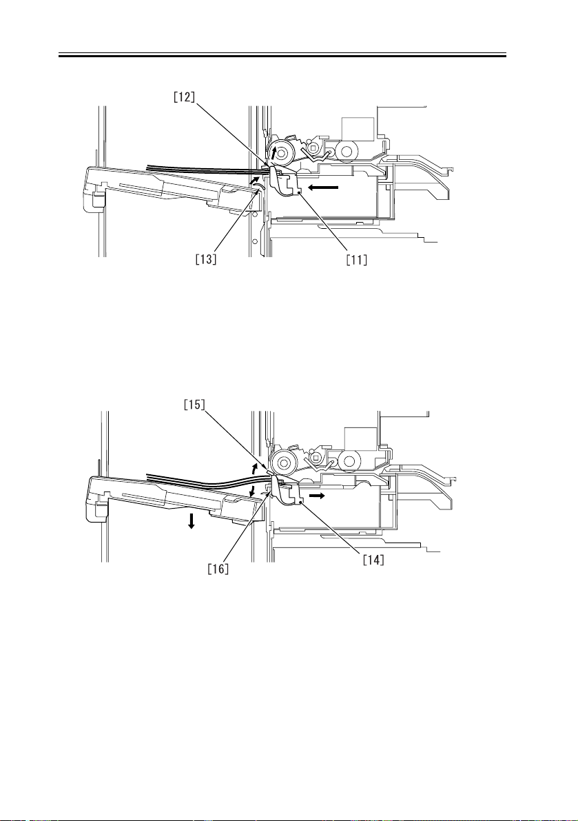
Chapter 2
F-2-8
15) The stack slider [14] moves in the opposite direction from the stack tray.
16) The lever of the paper holder [15] is engaged with the groove in the tray and the paper
holder opens while moving.
17) The stack stops at the return wall [16], falling into the stack stay.
F-2-9
2-6
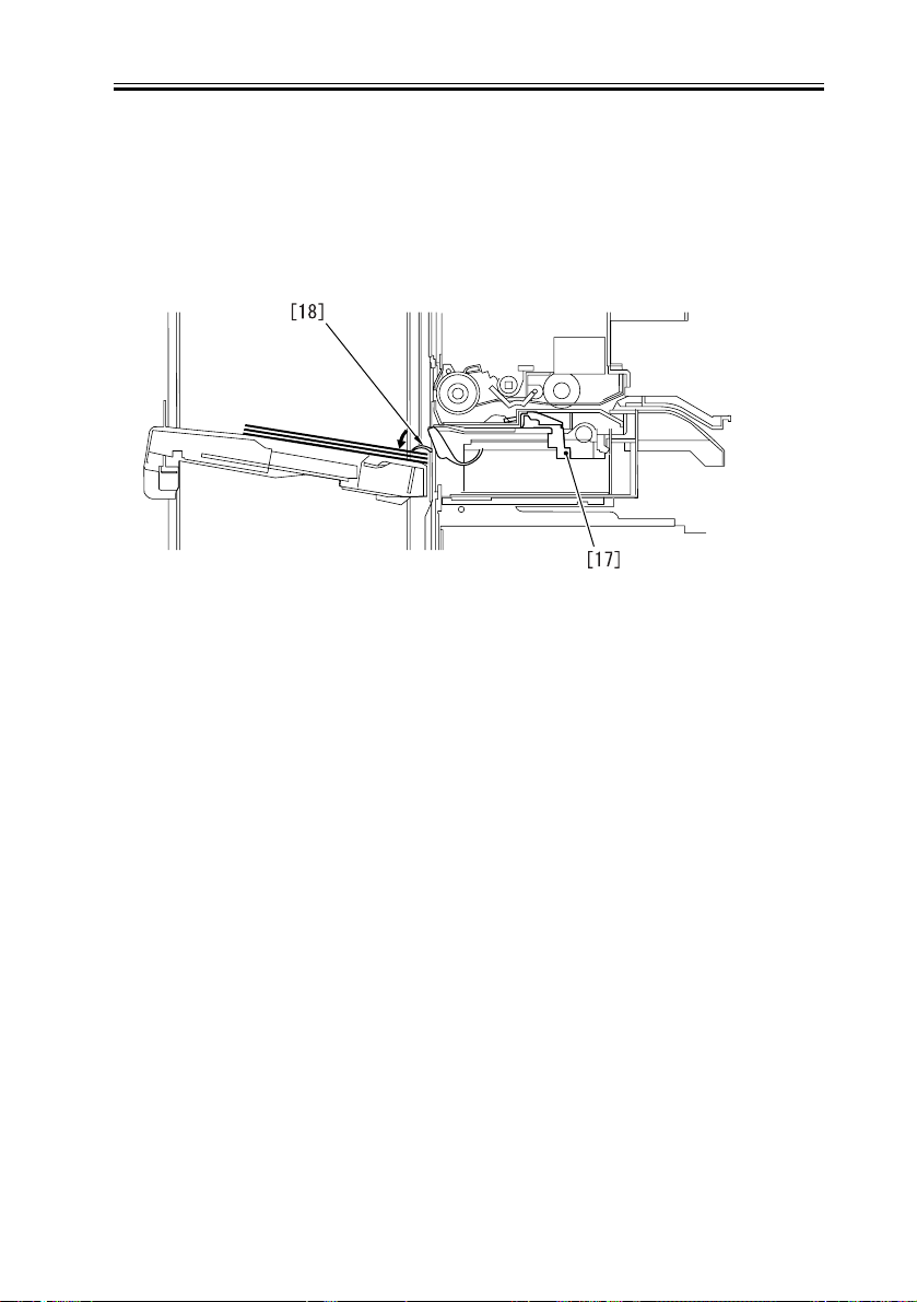
Chapter 2
17) The slider [17] moves to the original position.
18) The tray paper holder [18] catches hold of the sheets dropped in the stack tray.
F-2-10
2-7
Chapter 2
2.3 Feed Drive System
2.3.1 Overview
0006-1934
Sheets of paper fed from the host machine are put in the process tray.
The sheets are aligned and stapled in the process tray and then ejected to the stack tray.
The following illustration shows major components of the feed system.
M4
M1 M3[2]
M2
[4][3]
[1]
F-2-11
M1: Stach tray shift motor
M2: Feed motor
M3: Stack slide motor
M4: Offset motor
[1]: Finisher controller PCB
[2]: Paper surface sensor signal
[3]: Process tray papepr presence sensor signal
[4]: Inlet sensor signal
2-8
Chapter 2
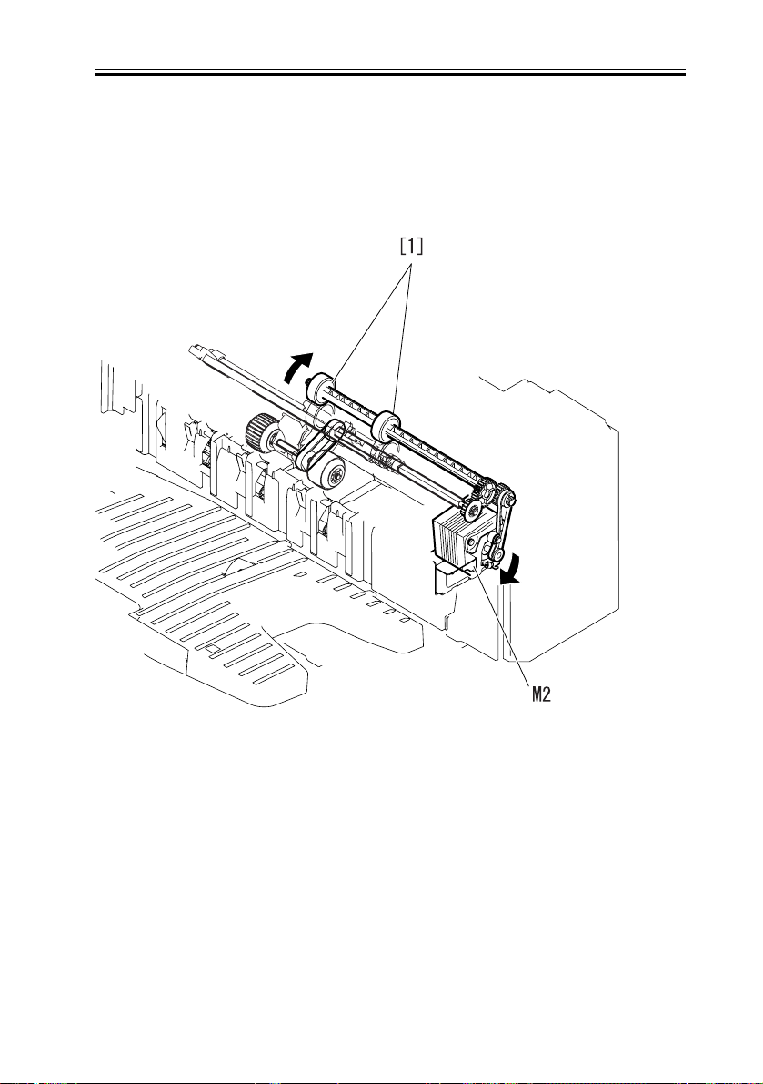
2.3.2 Feed Roller Control
The feed roller is driven by the feed motor (M2).
When the motor turns in the normal direction, the feed roller [1] is driven to eject paper
toward the stack tray.
0007-5484
F-2-12
2-9
 Loading...