

Canon Finisher-AB1, Saddle Finisher-AB2 Service Manual
SERVICE
MANUAL
Finisher-AB1
Saddle
Finisher-AB2
COPYRIGHT 2007 CANON INC. CANON Finisher-AB1 / Saddle Finisher-AB2 REV. 0 PRINTED IN U.S.A.
DU7-1230-000
MAY 2007
REV. 0

Application
This manual has been issued by Canon Inc. for qualified persons to learn technical theory, installation,
maintenance, and repair of products. This manual covers all localities where the products are sold. For this reason,
there may be information in this manual that does not apply to your locality.
Corrections
This manual may contain technical inaccuracies or typographical errors due to improvements or changes in
products. When changes occur in applicable products or in the contents of this manual, Canon will release technical
information as the need arises. In the event of major changes in the contents of this manual over a long or short
period, Canon will issue a new edition of this manual.
The following paragraph does not apply to any countries where such provisions are inconsistent with local law.
Trademarks
The product names and company names used in this manual are the registered trademarks of the individual
companies.
Copyright
This manual is copyrighted with all rights reserved. Under the copyright laws, this manual may not be copied,
reproduced or translated into another language, in whole or in part, without the written consent of Canon Inc.
COPYRIGHT © 2001 CANON INC.
Printed in Japan
Caution
Use of this manual should be strictly supervised to avoid disclosure of confidential information.

Introduction
Symbols Used
This documentation uses the following symbols to indicate special information:
Symbol Description
Indicates an item of a non-specific nature, possibly classified as Note, Caution, or
Warning.
Indicates an item requiring care to avoid electric shocks.
Indicates an item requiring care to avoid combustion (fire).
Indicates an item prohibiting disassembly to avoid electric shocks or problems.
Indicates an item requiring disconnection of the power plug from the electric outlet.
Indicates an item intended to provide notes assisting the understanding of the topic in
question.
Indicates an item of reference assisting the understanding of the topic in question.
Provides a description of a service mode.
Provides a description of the nature of an error indication.
Memo
REF.

Introduction
The following rules apply throughout this Service Manual:
1. Each chapter contains sections explaining the purpose of specific functions and the relationship between electrical and mechanical systems with reference to the timing of operation.
In the diagrams, represents the path of mechanical drive; where a signal name accompanies the
symbol, the arrow indicates the direction of the electric signal.
The expression "turn on the power" means flipping on the power switch, closing the front door, and closing
the delivery unit door, which results in supplying the machine with power.
2. In the digital circuits, '1'is used to indicate that the voltage level of a given signal is "High", while '0' is used
to indicate "Low".(The voltage value, however, differs from circuit to circuit.) In addition, the asterisk (*) as
in "DRMD*" indicates that the DRMD signal goes on when '0'.
In practically all cases, the internal mechanisms of a microprocessor cannot be checked in the field.
Therefore, the operations of the microprocessors used in the machines are not discussed: they are explained
in terms of from sensors to the input of the DC controller PCB and from the output of the DC controller PCB
to the loads.
The descriptions in this Service Manual are subject to change without notice for product improvement or other
purposes, and major changes will be communicated in the form of Service Information bulletins.
All service persons are expected to have a good understanding of the contents of this Service Manual and all
relevant Service Information bulletins and be able to identify and isolate faults in the machine."

Contents
Contents
Chapter 1 Specifications
1.1 Product Specifications...................................................................................... 1-1
1.1.1 Specifications (finisher) ............................................................................................. 1-1
1.2 Names of Parts.................................................................................................. 1-4
1.2.1 External View.............................................................................................................. 1-4
1.2.2 Cross Section ............................................................................................................. 1-5
Chapter 2 Installation
2.1 Making Pre-Checks........................................................................................... 2-1
2.1.1 Checking the Contents.............................................................................................. 2-1
2.2 Installation Procedure....................................................................................... 2-3
2.2.1 Points to Note When Turning ON/OFF the power of Host Machine.................. 2-3
2.2.2 Before Installing Finisher .......................................................................................... 2-3
2.2.3 Connecting with Machine.......................................................................................... 2-4
2.2.4 Connecting with High-Capacity Stacker ................................................................. 2-6
2.2.5 After Installation........................................................................................................ 2-10
2.3 Making Adjustments ....................................................................................... 2-11
2.3.1 Height Adjustment.................................................................................................... 2-11
2.4 Attaching the Labels etc................................................................................. 2-14
2.4.1 Affixing Labels .......................................................................................................... 2-14
Chapter 3 Functions
3.1 Basic Construction ............................................................................................ 3-1
3.1.1 Overview...................................................................................................................... 3-1
3.2 Electrical Control Unit....................................................................................... 3-2
3.2.1 Overview...................................................................................................................... 3-2
3.2.2 Finisher Controller PCB ............................................................................................ 3-3
3.3 Stacking Unit...................................................................................................... 3-4
3.3.1 Overview...................................................................................................................... 3-4
3.3.2 Tray Ascent/Descent Control ................................................................................... 3-5
3.3.3 Auxiliary Tray Lift Control.......................................................................................... 3-6
3.3.4 Tray Paper Surface Detection.................................................................................. 3-7
3.4 Feeding Unit....................................................................................................... 3-8

Contents
3.4.1 Overview..................................................................................................................... 3-8
3.4.2 Basic Sequence of Operations ............................................................................. 3-11
3.4.3 Horizontal Registration Detection......................................................................... 3-12
3.4.4 Horizontal Registration Correction/Alignment Operation .................................. 3-14
3.4.5 Buffer Operation ...................................................................................................... 3-17
3.4.6 Switching Over the Paper Path............................................................................. 3-19
3.5 Intermediate Process Tray Assembly........................................................... 3-20
3.5.1 Overview................................................................................................................... 3-20
3.5.2 Basic Sequence of Operations ............................................................................. 3-23
3.5.3 Stacking Operation ................................................................................................. 3-24
3.5.4 Alignment.................................................................................................................. 3-28
3.5.5 Stapling Operation .................................................................................................. 3-30
3.5.6 Delivery Operation .................................................................................................. 3-32
3.6 Detecting Jams................................................................................................. 3-33
3.6.1 Jam Detection in the Finisher Assembly ............................................................. 3-33
3.7 Power Supply ................................................................................................... 3-35
3.7.1 Overview................................................................................................................... 3-35
3.7.2 Protective Mechanism ............................................................................................ 3-36
Chapter 4 Parts Replacement Procedure
4.1 Removing from the Host Machine................................................................... 4-1
4.1.1 Finisher Assembly ..................................................................................................... 4-1
4.2 External Covers.................................................................................................. 4-2
4.2.1 Rear Lower Cover ..................................................................................................... 4-2
4.2.2 Rear Upper Cover ..................................................................................................... 4-2
4.2.3 Upper Cover Unit ...................................................................................................... 4-3
4.2.4 Delivery Tray .............................................................................................................. 4-4
4.2.5 Stack Wall (Upper) .................................................................................................... 4-5
4.2.6 Stack Wall (Lower) .................................................................................................... 4-5
4.2.7 Rear Middle Cover .................................................................................................... 4-6
4.2.8 Inside Cover (Upper) ................................................................................................ 4-6
4.2.9 Inside Cover (Lower) ................................................................................................ 4-7
4.3 Drive System ...................................................................................................... 4-7
4.3.1 Staple Unit .................................................................................................................. 4-8
4.3.2 Front Alignment Motor .............................................................................................. 4-9
4.3.3 Rear Alignment Motor .............................................................................................. 4-9
4.3.4 Tray Shift Motor ....................................................................................................... 4-11
4.3.5 Shift Motor ................................................................................................................ 4-12
4.3.6 Belt Controller Unit .................................................................................................. 4-15
4.4 Document Feeding System............................................................................ 4-18
4.4.1 Stack Delivery Roller .............................................................................................. 4-18

Contents
4.4.2 Process Tray Assembly ..........................................................................................4-20
4.4.3 Process Tray .............................................................................................................4-21
4.4.4 Feed Belt ...................................................................................................................4-22
4.4.5 Paddle Unit ................................................................................................................4-24
4.4.6 Paddle ........................................................................................................................4-24
4.4.7 Tray Unit ....................................................................................................................4-24
4.5 Electrical System............................................................................................. 4-28
4.5.1 Finisher Controller PCB ..........................................................................................4-28
4.5.2 Static Charge Eliminator .........................................................................................4-28
4.5.3 Horizontal Registration Sensor Unit ......................................................................4-30
Chapter 5 Maintenance
5.1 User Maintenance............................................................................................. 5-1
5.1.1 User Maintenance Items (finisher) .......................................................................... 5-1
5.2 Maintenance and Inspection ........................................................................... 5-1
5.2.1 Periodically Replaced Parts .....................................................................................5-1
5.2.1.1 Periodically Replaced Parts in the Finisher...................................................................... 5-1
5.2.2 Durables ......................................................................................................................5-1
5.2.2.1 Durables in the Finisher ...................................................................................................... 5-1
5.2.2.2 Durables in the Saddle Stitcher.......................................................................................... 5-2
5.2.3 Periodical Servicing ...................................................................................................5-2
5.2.3.1 Scheduled Servicing for the Finisher ................................................................................ 5-2
5.2.3.2 Scheduled Servicing for the Saddle Stitcher.................................................................... 5-2
5.3 Adjustment ......................................................................................................... 5-3
5.3.1 Basic Adjustment .......................................................................................................5-3
5.3.1.1 Adjusting the Height ............................................................................................................. 5-3
5.3.1.2 Adjusting the Horizontal Registration/Angle..................................................................... 5-6
5.3.1.3 Adjusting the Sensor Intensity............................................................................................ 5-8
5.3.2 Adjustment at Time of Parts Replacement ..........................................................5-10
5.3.2.1 Adjusting the Tray A/B Position........................................................................................ 5-10
5.3.2.2 Adjusting the Angle of the Aligning Plate (orthogonal) ................................................. 5-11
5.3.2.3 Adjusting the Stapler Position .......................................................................................... 5-12
5.3.2.4 Adjusting the Speed of the Swing Guide ........................................................................ 5-12
5.3.2.5 Adjusting the Aligning Plate Width................................................................................... 5-13
5.3.2.6 Adjusting the Transport Belt Position .............................................................................. 5-16
5.3.2.7 Adjusting the Stapling Position (rear 1-point) ................................................................ 5-17
5.3.2.8 Adjusting the Stapling Position (front 1-point)................................................................ 5-20
5.3.2.9 Adjusting the Stapling Position (2-point)......................................................................... 5-22
5.3.2.10 Adjusting the Delivery of Stapled Stacks (lower delivery).......................................... 5-25
5.3.2.11 Adjustment of EEPROM (IC107) on the Finisher Controller PCB After Replacement 5-
27
5.3.2.12 Bufferless mode 1 ............................................................................................................ 5-29

Contents
5.3.2.13 Bufferless mode 2 ............................................................................................................ 5-30
5.3.2.14 Assist stopper position adjustment................................................................................ 5-30
5.3.2.15 Staple inlet guide height adjustment............................................................................. 5-32
5.3.2.16 Paddle height adjustment .............................................................................................. 5-34
5.3.2.17 Adjustment at poor tray stackability (when the upper curl occurs) ......................... 5-36
5.3.2.18 Adjustment at poor tray stackability (when the lower curl occurs) .......................... 5-37
5.3.2.19 Adjustment at poor tray stackability (run over when using thin paper) ................... 5-39
5.3.2.20 Tray stacking limit cancellation adjustment ................................................................. 5-41
5.3.2.21 Saddle staple alignment adjustment............................................................................. 5-43
5.3.2.22 Saddle disengage roller position adjustment............................................................... 5-46
5.3.2.23 The amount of sending of a saddle disengage roller adjustment............................. 5-49
5.3.2.24 Saddle staple position adjustment................................................................................. 5-51
5.3.3 Other ......................................................................................................................... 5-53
5.3.3.1 Service Mode (by DIP switch)<Incerter>........................................................................ 5-53
5.4 Troubleshooting ............................................................................................... 5-56
5.4.1 Malfunction ............................................................................................................... 5-56
5.4.1.1 Malfunction/Faulty Detection............................................................................................ 5-56
5.5 Outline of Electrical Components.................................................................. 5-58
5.5.1 Sensors (Finisher Unit)........................................................................................... 5-58
5.5.2 Microswitches (Finisher Unit) ................................................................................ 5-62
5.5.3 Solenoids (Finisher Unit)........................................................................................ 5-64
5.5.4 Motors (Finisher Unit) ............................................................................................. 5-66
5.5.5 Fans (Finisher Unit) ................................................................................................ 5-69
5.5.6 PCBs (Finisher Unit)............................................................................................... 5-70
5.6 Variable Resistors (VR), Light-Emitting Diodes (LED), and Check Pins by PCB
5-71
5.6.1 Overview................................................................................................................... 5-71
5.6.2 Finisher Controller PCB ......................................................................................... 5-71
5.7 Upgrading.......................................................................................................... 5-72
5.7.1 Upgrading ................................................................................................................. 5-72
5.8 Service Tools.................................................................................................... 5-72
5.8.1 Solvents and Oils .................................................................................................... 5-72
Chapter 6 Error Code
6.1 Jam Codes.......................................................................................................... 6-1
6.1.1 Jam Codes ................................................................................................................. 6-1
6.2 Error Codes......................................................................................................... 6-2
6.2.1 Error Codes .................................................................................................................. 6-2

Chapter 1
SPECIFICATIONS

Contents
Contents
1.1 Product Specifications .......................................................................................... 1-1
1.1.1 Specifications (finisher).................................................................................................1-1
1.2 Names of Parts...................................................................................................... 1-4
1.2.1 External View ................................................................................................................1-4
1.2.2 Cross Section .................................................................................................................1-5

Chapter 1
1-1
1.1 Product Specifications
1.1.1 Specifications (finisher)
0015-2057
T-1-1
Item Description Remarks
Stacking
mechanism
tray A/B by tray lift
Stacking orientation tray A face-down/face-up
tray B face-down
Stack size tray A A3,A4,A4R,A5R,B4,B5,B5R,Jpn postcard
R,279.4mmx432.8mm(11x17),LGL,LTR,EXE,LT
RR,STMTR,EXER
in feed direction, 182 to 487.7 mm;
in cross-feed direction,139.7 to
320.2 mm
tray B A3,A4,A4R,B4,B5,B5R,279.4mmx432.8mm(11x
17),LGL,LTR,EXE,LTRR,EXER
in feed direction, 182 to 457.2 mm;
in cross-feed direction, 182 to
304.8mm
Types of Paper Plain paper (64g/m2 to 90g/m2), Heavy paper (91 g/m2 to 200 g/
m2), Recycled paper, Colored paper, Postcard, Label, Index
paper, Tracing paper, 3-hole paper.
Number of trays 2
Mode type non-staple, staple
Number of sheets
(Note 1)
non-staple
sort
tray A: if small-/large-size, equivalent of 1000
sheets(147 mm in height)
in multiple mode, the number of
sheets are as follows:
if small-size, equivalent of 3000
sheets (423 mm in height); if largesize, 1500 sheets (216 mm in height)
tray B: if small-size, equivalent of 2000 sheets
(285mm in height),if large-size, equivalent of 1000
sheets(147 mm in height)
staple sort tray A: if small-/large-size, equivalent of 1000
sheets (147 mm in height), or 100 sets
tray B: if small-size, equivalent of 2000 sheets (285
mm in height), or 100 sets; if large-size, equivalent
of 1000 sheets (147 mm in height), or 100 sets
Staple/non-staple
mix (Note 1)
if small-size, equivalent of 200 sets (285 m in height), or 100 sets;
if large-size, equivalent of 100 sheets(9147 mm in height), or 100
sets
applicable to tray B only
Folded sheet mix
(Note 1)
tray A: 10 folded sheets max. per set/20 folded sheets max. per job
tray B: 10 folded sheets max. per set/30 folded sheets max. per job
Stapling method stapling by rotating cam
Stapled stack if small-size, 100 sheets as converted with reference to paper
of 80g/m2
if large-size, 50 sheets

Chapter 1
1-2
1: The number of sheets refers to the result of conversion based on paper of 80g/m2
2: A sheet of paper may be grouped into the following:
-large-size; A3,B4,279.4mmx432.8mm(11x17),LGL
-small-size; A4,A5,B5,EXE,LTR,STMT,postcard,A4R,B5R,LTRR
T-1-2
Item Description Remarks
Staple accommodation in special staple cartridge (5000 staples)
Detection of staples yes an alert condition
identified at 0 to 40
staples
Manual stapling no
Stack size front 1-point
A3,A4,A4R,B4,B5,279.4mmx432.8mm(11x17),EXE,LGL,LTR,
LTRR
rear 1-point
A3,A4,A4R,B4,B5,279.4mmx432.8mm(11x17),EXE,LGL,LTR,
LTRR
2-point
A3,A4,A4R,B4,B5,279.4mmx432.8mm(11x17),EXE,LGL,LTR,
LTRR
Paper detection yes
Control panel no
Display no
Dimensions W:800xD:786xH:1180mm
Weight 126 kg (approx.)
Power supply 100V,200-240V
Maximum power
consumption
360 W or less
Chapter 1
1-3
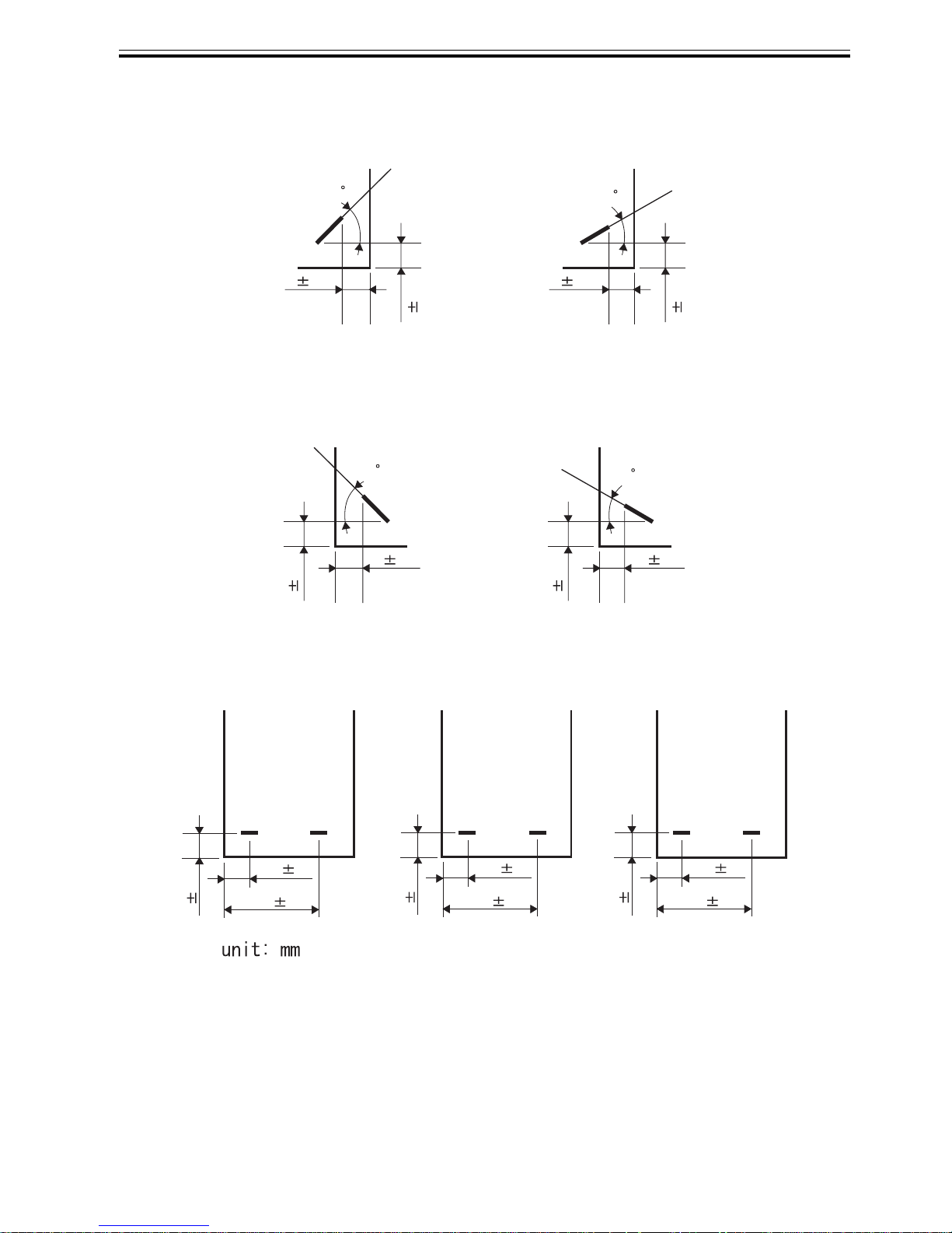
Staple Position
1-Point Stapling (front)
1-Point Stapling (rear)
2-Point Stapling
A3, A4 B4, B5
5 2.0
73.7 4.0
193.7
4.0
5 2.0
62.7 4.0
182.7
4.0
5 2.0
82.7 4.0
202.7
4.0
5 2.0
45
5 2.0
5 2.0
30
5 2.0
5 2.0
45
A3, B4, A4, B5, / 11"x17", LTR
5
2.0
5 2.0
30
A4R / LGL, LTRR
A3, B4, A4, B5, / 11"x17", LTR A4R / LGL, LTRR
5
2.0
11"x17", LTR
Chapter 1
1-4
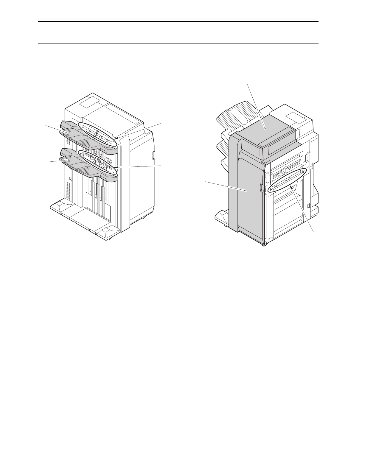
1.2 Names of Parts
1.2.1 External View
0015-2060
F-1-1
[1]Tray B [5]Upper cover
[2]Tray A [6]Inlet transport unit
[3]Top delivery outlet [7]Front cover
[4]Bottom delivery outlet
[1]
[2]
[3]
[4]
[5]
[6]
[7]
Chapter 1
1-5
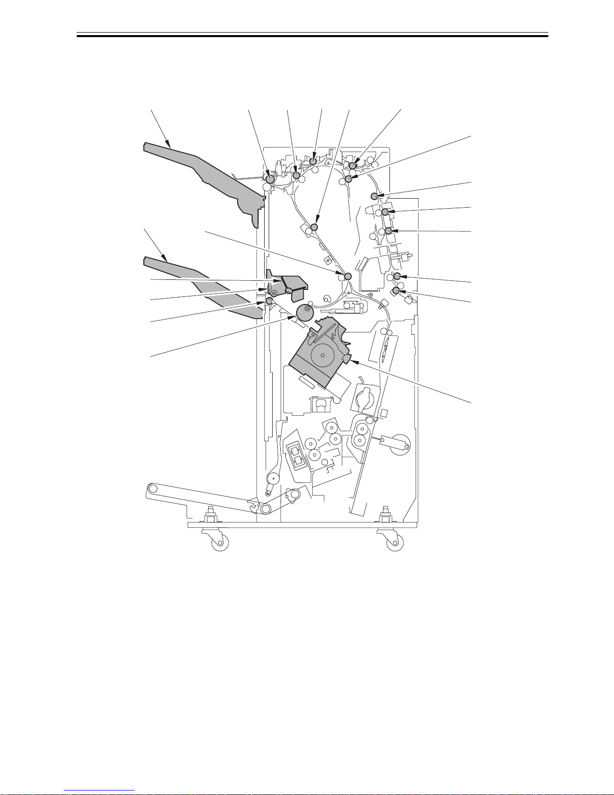
1.2.2 Cross Section
0015-2062
F-1-2
[1]Transport belt [8]Delivery roller [14]Assist roller 2
[2]Stack delivery roller [9]Buffer roller 2 [15]Shift roller 2
[3]Swing guide [10]Assist roller 3 [16]Shift roller 1
[4]Paddle [11]Buffer roller 3 [17]Assist roller 1
[5]Tray B [12]Transport roller [18]Inlet transport roller
[6]Stack transport roller [13]Buffer roller 1 [19]Stapler
[7]Tray A
[1]
[2]
[3]
[4]
[5]
[7] [8] [9]
[6]
[10]
[11]
[12]
[13]
[14]
[15]
[16]
[17]
[18]
[19]

Chapter 2
INSTALLATION

Contents
Contents
2.1 Making Pre-Checks........................................................................................... 2-1
2.1.1 Checking the Contents.............................................................................................. 2-1
2.2 Installation Procedure....................................................................................... 2-3
2.2.1 Points to Note When Turning ON/OFF the power of Host Machine.................. 2-3
2.2.2 Before Installing Finisher .......................................................................................... 2-3
2.2.3 Connecting with Machine.......................................................................................... 2-4
2.2.4 Connecting with High-Capacity Stacker ................................................................. 2-6
2.2.5 After Installation........................................................................................................ 2-10
2.3 Making Adjustments ....................................................................................... 2-11
2.3.1 Height Adjustment.................................................................................................... 2-11
2.4 Attaching the Labels etc................................................................................. 2-14
2.4.1 Affixing Labels .......................................................................................................... 2-14
Chapter 2
2-1
2.1 Making Pre-Checks
2.1.1 Checking the Contents
0016-0898
F-2-1
FU5-8941
M_ _ ________ ___ _________ ___________ __ _____ ____________.
P_ _ ______ ___ __________ _____ ____________ ___ _____________.
J_ ____ ____________ ___ ________ _____ ___ _______ _____________ _________.
P____ ___ ________ __ __ _________ _____ ___ ___________ ___ __________.
P_______ _______ ____ _____ _ ________ ____ ______________.
P___ ___ ________ __ _____ ___________ ___ _____ __ _____________.
_______________________________.
_______________________________.
_____________________________________.
___________________________________________.
[4]
[9]
[3]
[9]
[13] [15]
[9]
[2]
[9][5] [7][6]
[10]
[8]
[17]
[1]
1
[11]
2
[16]
4
[18]
3
[19]
5
[12]
3
[14]
3

Chapter 2
2-2
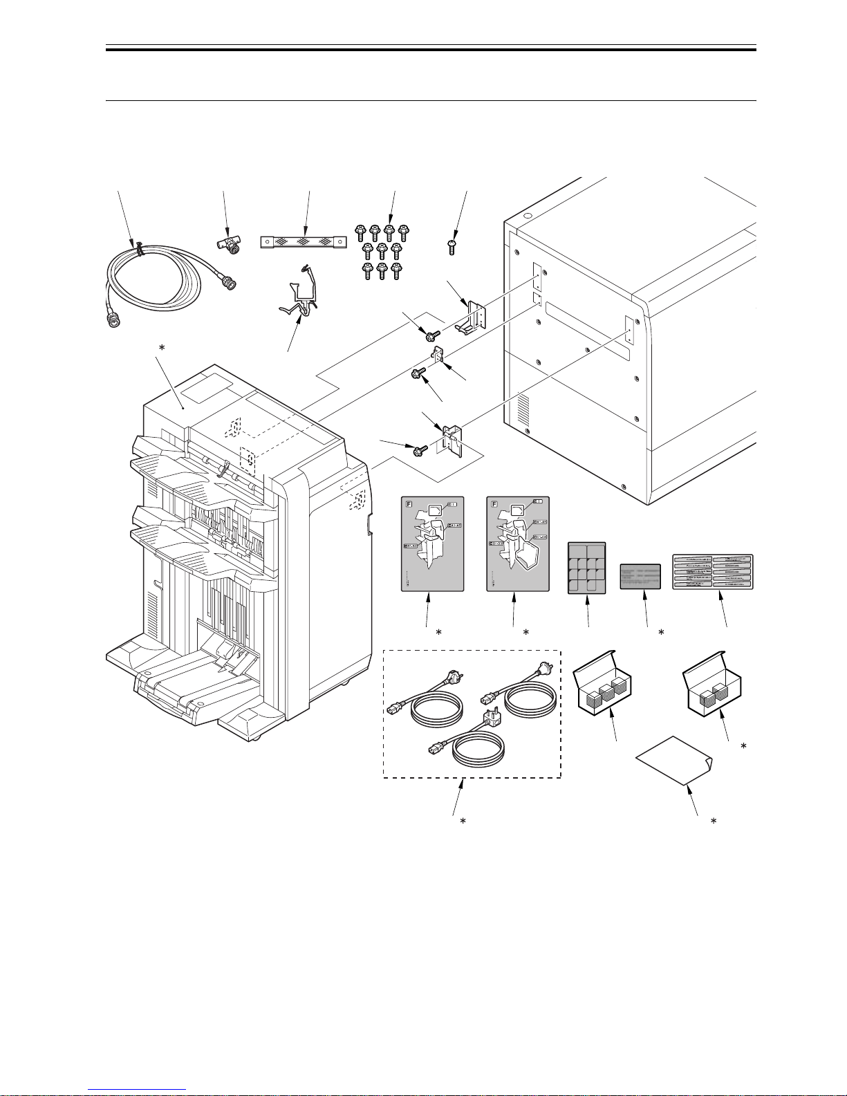
[1]*1 Finisher 1pc [2] Latch plate (for front) 1pc
[3] Latch plate (for rear) 1pc [4] Positioning Pin 1pc
[5] ARCNET cable 1pc [6] coaxial connector 1pc
[7] Shunt Cable 1pc [8] Wire Saddle 1pc
[9] Screws (RS tight; M4X10) 10pc [10] Screw (Bind; M4X8) 1pc
[11]*2 Guide map label 1pc [12]*3 Guide map label 1pc
[13] Staple label 1pc [14]*3 LED Lamp Label
(products for China, Korea and
Taiwan)
1pc
[15] jam removal label 1pc [16]*4 Power Cable
3pc
[17] Staple cartridge 3pc [18]*3 Saddle staple cartridge 2pc
[19]*5 Sheet, FCC Class A 1pc
*1: The figure shows Saddle Finisher AB2.
*2: Included only for Finisher AB1.
*3: Included only for Saddle Finisher AB2.
*4: Perform only for EUR. Use the appropriate power code for relevant country/area. Bring back unused
power codes.
*5: Included only for UL.
Chapter 2
2-3
2.2 Installation Procedure
2.2.1 Points to Note When Turning
ON/OFF the power of Host
Machine
0016-5236
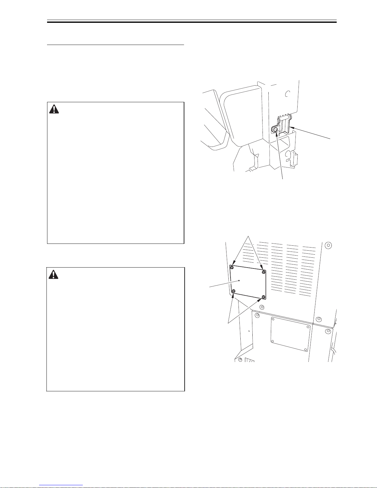
2.2.2 Before Installing Finisher
0016-0901
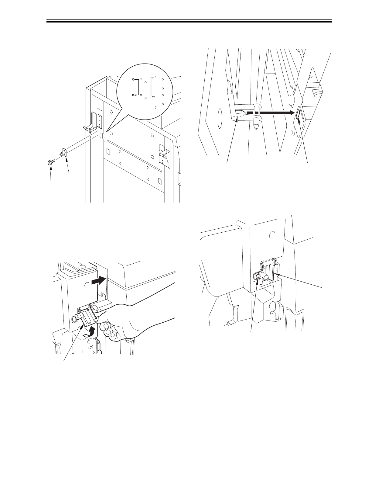
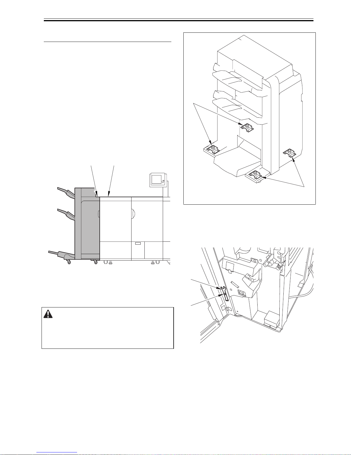
1) Open the front cover of the finisher.
2) Remove 1 screw [2] from the front latch retainer
[1].
F-2-2
3) Detach the rear small cover [1].
- 4 screws [2]
F-2-3
Power-On Order for Turning On the
Power When Pickup/Delivery Accessories
are Connected
Be sure to turn on the power in the correct
order otherwise it may cause an error because
the host machine fails to recognize
accessories including this equipment.
<Power-On Order>
1) Accessories (accessories including this
equipment)
2) Host machine
MEMO:
There is no power-on order among
accessories
Points to Note When Turning Off the
Main Power of the Host Machine
Be sure to turn off the main power in the
following order to protect hard disk of the host
machine.
1) Press the power switch on control panel for
3 sec or more.
2) Follow the instruction on the shutdown
sequence screen (the main power switch will
go off automatically).
3) Turn off the breaker.
4) Disconnect the power plug.
[2]
[1]
[2]
[2]
[1]
Chapter 2
2-4
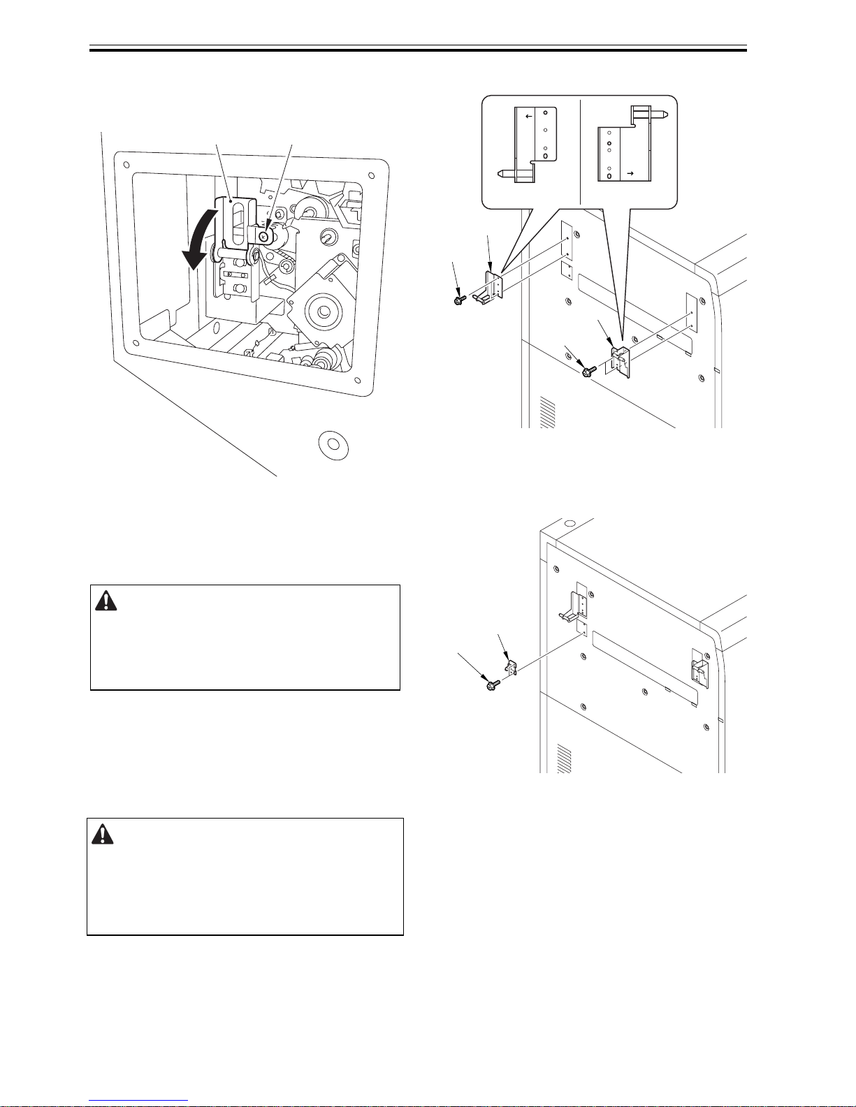
4) Remove 1 screw [1] on the rear latch retainer and
pull the hinge [2] forward and downward.
F-2-4
2.2.3 Connecting with Machine
0016-0903
1) Sub-Station Upper Left Cover [1] and rear [2]
latch plates.
- 4 screws (RS tight; M4X10) [3]
F-2-5
2) Fit the positioning pin [1].
- 2 screws (RS tight; M4X10) [2]
F-2-6
Check the power on the host machine is
surely turned off and the power supply cable
is unplugged.
Confirm the mark engraved on each latch plate
when attaching.
Front [1]: F
Rear [2]: R
[1][2]
[1]
[3]
R
F
[1][2]
[3]
[2]
[1]
[2]
Chapter 2
2-5
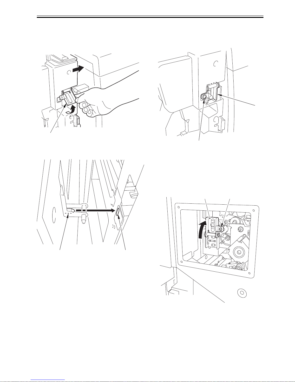
3) While lifting up the front latch plate [1], fit the
positioning pin on the machine side [2] to the
finisher's positioning hole [3]. Connect the
finisher with the machine.
<Front side>
F-2-7
<Rear side>
F-2-8
4) Fix the front latch retainer.
- 1 screw [2] (Use the screw removed in the step
2 of "Before Installing Finisher")
F-2-9
5) Shut the front cover of the finisher.
6) Lift up the rear latch plate [1] to fit the pin and fix
it.
- 1 screw [2] (Use the screw removed in the step
4 of "Before Installing Finisher")
F-2-10
[1]
[2]
[3]
[2]
[1]
[2][1]

Chapter 2
2-6
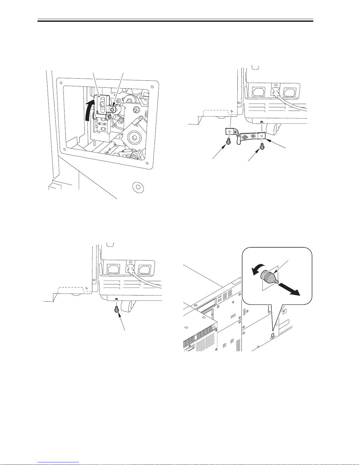
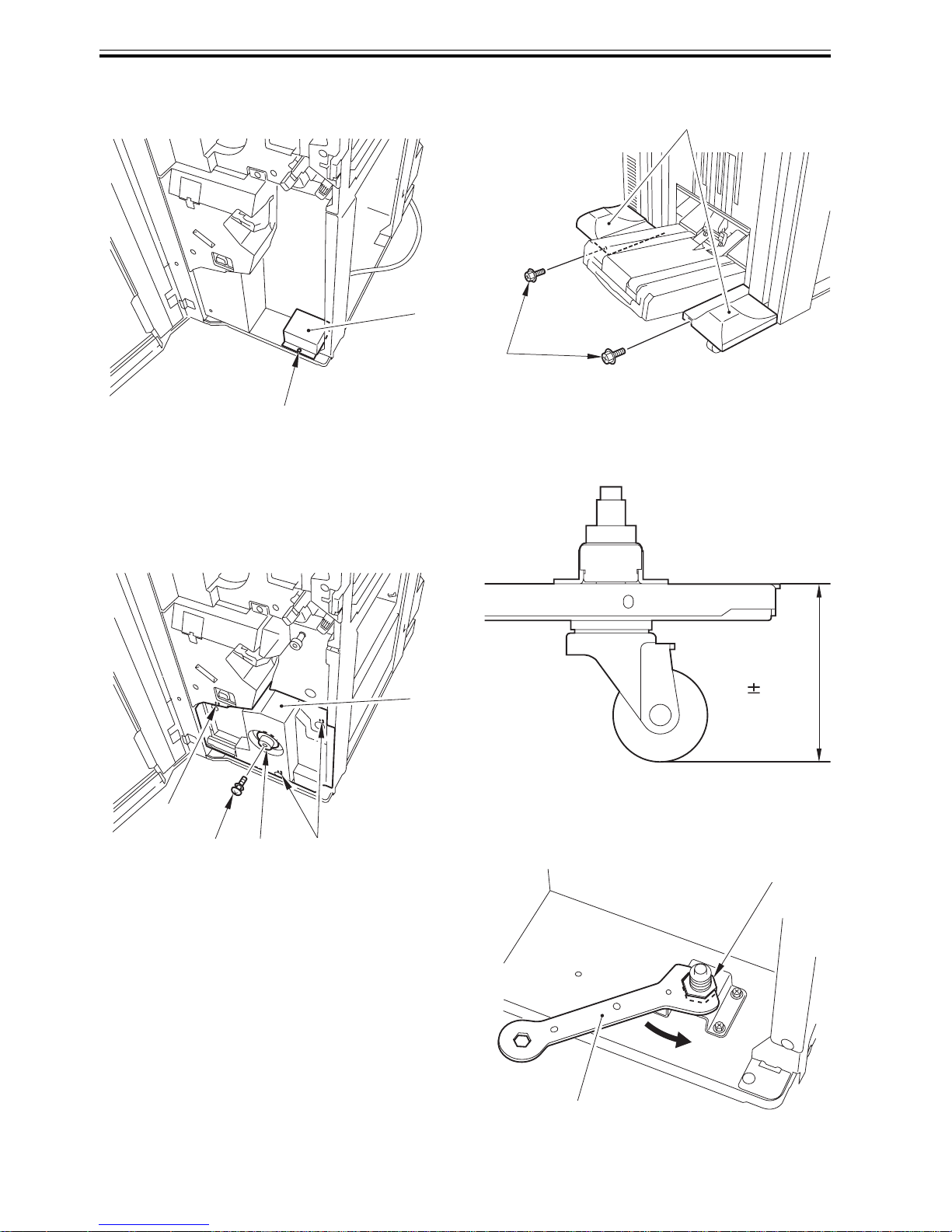
7) Attach the rear small cover.
8) Remove 1 screw [1] on the rear lower cover of the
finisher.
F-2-11
9) Connect the shunt cable [1].
- 1 screw (User the ones removed in step 8).
- 1 screw (Use the included screw for the
finisher.)
F-2-12
2.2.4 Connecting with High-Capacity
Stacker
0016-0904
1) Attach the front [1] and rear [2] latch plates to the
left side of the high-capacity stacker.
- 4 screws (RS tight; M4X10)
F-2-13
Check the power on the host machine is surely
turned off and the power supply cable is
unplugged.
[1]
[2]
[1]
Confirm the mark engraved on each latch plate
when attaching.
Front [1]: F
Rear [2]: R
[3] [1]
[3]
[2]
[1][2]
R
F
Chapter 2
2-7
2) Fit the positioning pin [1] of the high-capacity
stacker to the position [A].
- 2 screws [2]
F-2-14
3) While lifting up the front latch support [1], fit the
positioning pin [2] of the high-capacity stacker to
the positioning plate hole [3] on the finisher for
connection.
<Front side>
F-2-15
<Rear side>
F-2-16
4) Fix the front latch plate (front) [1].
- 1 screw [2] (Use the screw removed in step 2 of
"Before Installing Finisher")
F-2-17
5) Close the front cover of the finisher.
[2]
[1]
[A]
[1]
[2]
[3]
[2]
[1]
Chapter 2
2-8
6) Lift up the rear latch plate [1] to fit the pin and fix
it.
- 1 screw [2] (Use the screw removed in step 4 of
"Before Installing Finisher")
F-2-18
7) Attach the rear small cover.
8) Remove 1 screw [1] on the rear lower cover of the
finisher.
F-2-19
9) Connect the shunt cable [1].
- 1 screw (Use the ones removed in step 8.)
- 1 screw (Use the included screw for the highcapacity stacker.)
F-2-20
10) See "After Installation" to connect the ARCNET
cable to the high-capacity stacker and the
finisher.
2.2.5 After Installation
0016-0907
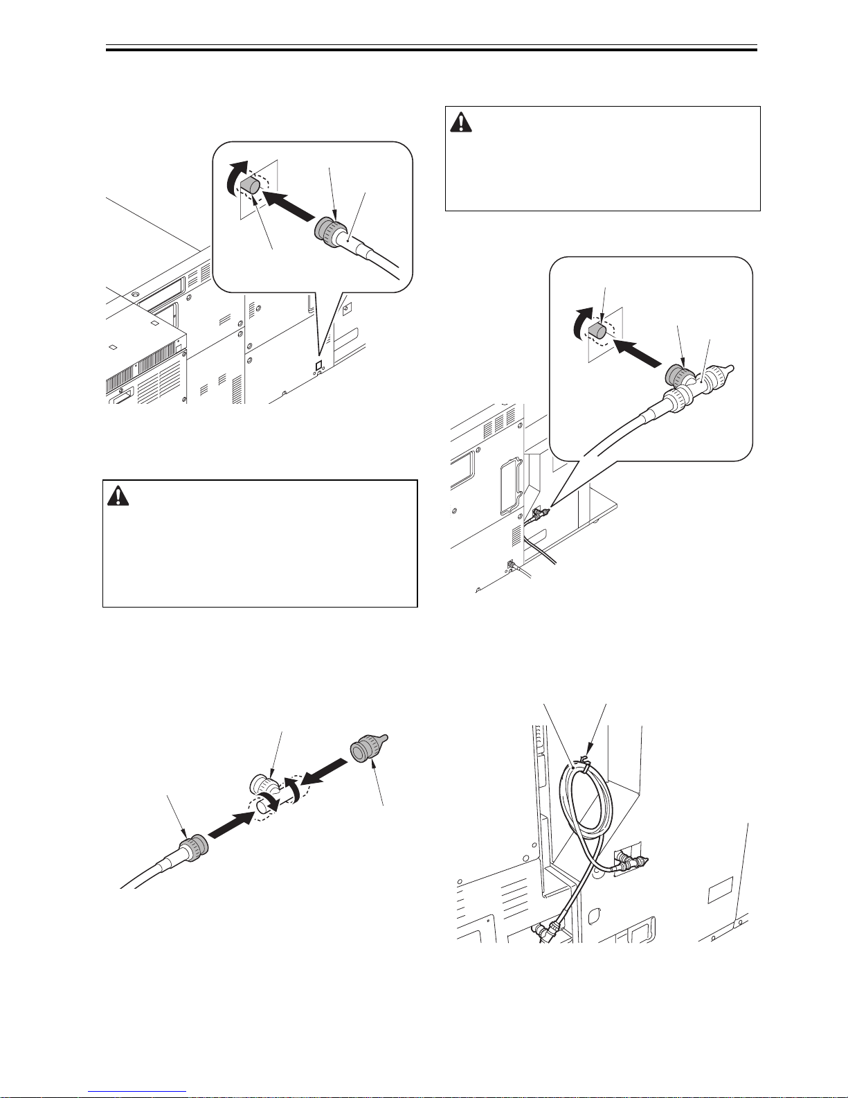
1) Free the terminal connector [1] from the sub
station.
F-2-21
[2][1]
[1]
[2]
[1]
[3]
[1]
Chapter 2
2-9
2) Connect the ARCNET cable [1] to the terminal [2]
at sub station, and then turn the finger grip [3] in
the direction of the arrow to connect.
F-2-22
3) Put the end terminal connector [2] and the
ARCNET cable [3] to the coaxial connector [1],
and turn each of then in the direction of the arrow
to connect.
F-2-23
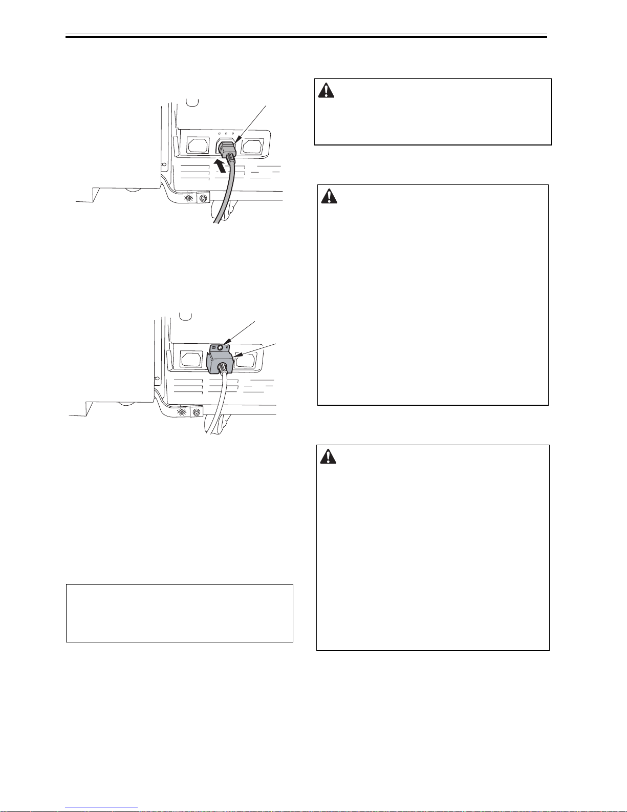
4) Connect the ARCNET cable [1] to the terminal [2]
at finisher, and then turn the finger grip [3] in the
direction of the arrow to connect.
F-2-24
5) Attach the wire saddle [1] to the rear lower cover
of the finisher to bundle the signal cable [2] on it.
F-2-25
Rotate the ARCNET cable until they are fully
fixed, or the electrical contact can be unstable.
[1]
[3]
[2]
[2]
[1]
[3]
Be sure to turn off the host machine and unplug the
power supply cable when connecting the ARCNET
cable.
[2]
[2]
[1]
[3]
[1][2]
Chapter 2
2-10
6) Connect the power supply plug of the finisher.
(Perform only for EUR)
F-2-26
7) For Finisher /Saddle Finisher , connect the power
supply cable to the host machine. (Perform only
for EUR)
- 1 screw (bind; M4X8) [2]
F-2-27
8) Plug the power supply cable of the machine in the
power outlet.
9) Turn on the power switch on the finisher, and then
turn on the host machine.
10) Enter the service mode and set the connection
sequence.
Choose the item with "Finisher" displayed from
COPIER>OPTION>ACCPST-D>ACC1 to 8 to
enter the connection sequence of the finisher.
11) Follow the shutdown sequence to turn off the
power switch of the host machine/finisher.
12) Turn on the power switch of the finisher and then
that of the host machine.
MEMO:
When connecting to the host machine directly,
enter "1" and press "OK".
[1]
[1]
[2]
After setting the connection sequence, the host
machine should be turned off and on to enable the
setting.
Power-On Order for Turning On the
Power When Pickup/Delivery Accessories
are Connected
Be sure to turn on the power in the correct
order otherwise it may cause an error because
the host machine fails to recognize accessories
including this equipment.
<Power-On Order>
1) Accessories (accessories including this
equipment)
2) Host machine
MEMO:
There is no power-on order among accessories
Points to Note When Turning Off the
Main Power of the Host Machine
Be sure to turn off the main power in the
following order to protect hard disk of the host
machine.
1) Press the power switch on control panel for
3 sec or more.
2) Follow the instruction on the shutdown
sequence screen (the main power switch will
go off automatically).
3) Turn off the breaker.
4) Disconnect the power plug.
Chapter 2
2-11
2.3 Making Adjustments
2.3.1 Height Adjustment
0016-1444
Depending on the floor condition of an installation
site, you should adjust the height of the finisher. If
not properly adjusted, paper might be jammed more
frequently in the feeder assembly. Follow the steps
below to adjust the height when it is necessary.
1. 1. Checking the height
1) Check the height of the finisher and the main
station. The height difference between the right
top of the finisher [1] and the left top of the main
station [2] should be within 2mm.
F-2-28
2) If the difference exceeds 2mm, adjust the height.
2. Height adjustment
1) Disconnect the finisher from the main station.
2) Remove the wrench [1] from the finisher front
cover.
- 1 screw [2]
F-2-29
Adjust the height with 4 casters [1] as shown in
the figure.
[1] [2]
[1]
[1]
1]
2
]
Chapter 2
2-12
3) For Finisher AB1, detach the caster front cover.
- 1 screw [2]
F-2-30
4) For Saddle Finisher, detach the saddle inner cover
(lower) [1].
- 1 screw [2]
- 1 knob [3]
- 3 screws [4]
F-2-31
5) Detach 2 caster covers [1] on the left side of the
equipment. (Figure shows Saddle Finisher.)
- 2 screws [2]
F-2-32
6) Measure the height [A] from the floor to the
bottom of the machine to check the figure is in the
range of 84.6+ -0.5mm.
F-2-33
7) Loosen the fixing nut [1] with the wrench [2] in
the direction of [A].
F-2-34
[1]
[2]
[1]
[2] [3]
[4]
[4]
[2]
[1]
84.6 0.5mm
[A]
[1]
[2]
[A]
Chapter 2
2-13
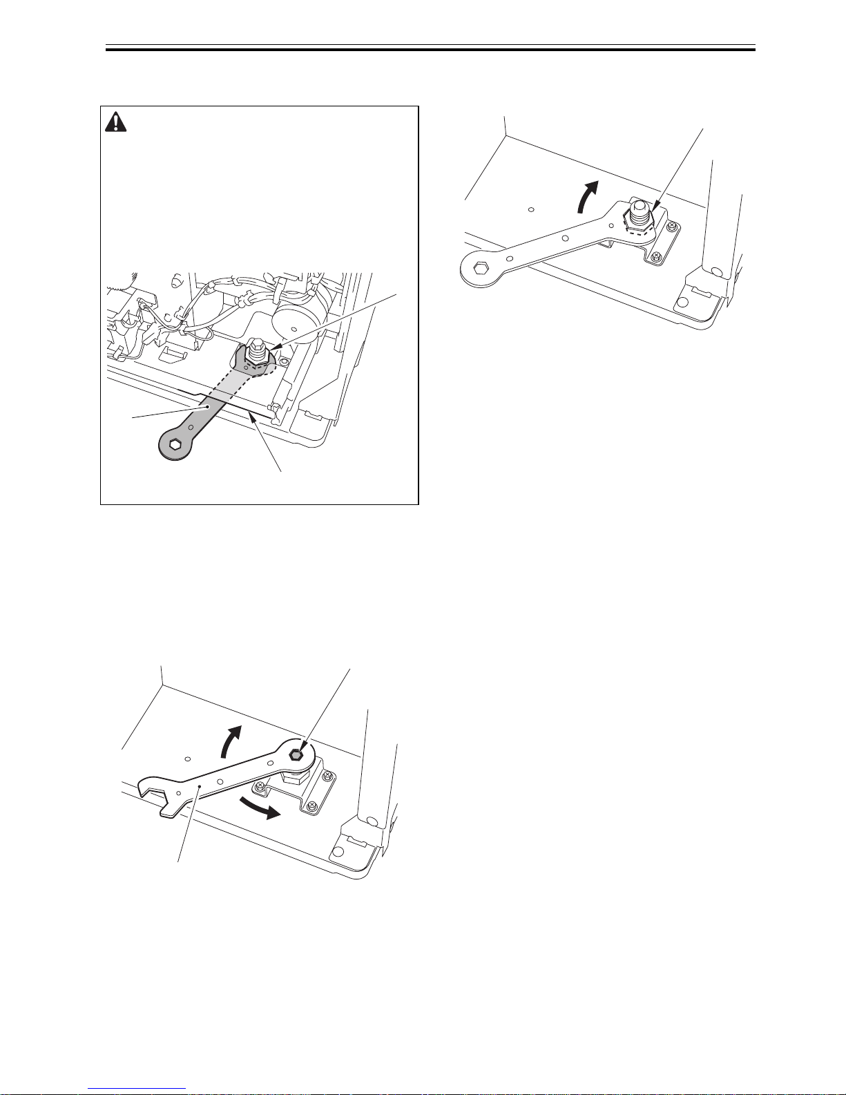
8) Rotate the adjusting bolt [1] with the wrench
(small) [2] to adjust the height in the range of
84.6+ -0.5mm.
- To increase the height: rotate in the direction of
[A]
- To lower the height: rotate in the direction of [B]
(Height change per rotation: approx. 1.75 mm)
F-2-35
9) Tighten the fixing nut [1] in the direction of [B].
F-2-36
10) Repeat the steps above to adjust the height of
other 3 casters.
11) Connect the finisher to the host machine again to
check the height.
Attach the cover and other parts removed in the
previous steps if the height difference is in the
tolerable range. If not, repeat the steps above to
readjust the height.
When loosening the fixing nut on the front
caster of the saddle finisher, insert the wrench
[3] into the opening just below the saddle
bottom plate [2].
[1]
[2]
[3]
[1]
[2]
[A]
[B]
[1]
[B]
 Loading...