


i
CONTENTS
1 |
INTRODUCTION/INSTALLATION |
1 |
|
|
|
The miniAV®-XAutomatic Viscometer .................................................................................. |
|
|
1 |
|
Measuring kinematic viscosity ............................................................................................... |
|
|
2 |
|
Safety cautions ..................................................................................................................... |
|
|
2 |
|
Specifications ....................................................................................................................... |
|
|
4 |
|
Installation ............................................................................................................................ |
|
|
4 |
|
Required installation components ............................................................................... |
|
|
4 |
|
Vacuum Pump unit connections ................................................................................. |
|
|
6 |
|
Bath unit connections ................................................................................................ |
|
|
6 |
|
VISCPRO® for Windows® XP® ............................................................................................ |
|
|
6 |
|
Installing VISCPRO® software .............................................................................................. |
|
|
7 |
|
Computer requirements ............................................................................................. |
|
|
7 |
|
Windows® XP® installation ........................................................................................ |
|
|
7 |
|
Installation actions ..................................................................................................... |
|
|
7 |
|
Configuration diskette (First-time installation only!) .................................................... |
|
|
7 |
|
Running the software ............................................................................................................. |
|
|
8 |
|
Checking configuration .......................................................................................................... |
|
|
9 |
|
InitalConfiguration .................................................................................................... |
|
|
9 |
|
Loggingin ............................................................................................................... |
|
|
10 |
|
Checking Instrument Settings .................................................................................. |
|
|
10 |
|
Viewing/editingsetupinformation ............................................................................. |
|
|
12 |
|
Manually changing tube calibration constants ....................................................................... |
|
|
13 |
|
Checking Wash andAdvanced Settings ............................................................................... |
|
|
14 |
|
Preparing the miniAV-X for testing ...................................................................................... |
|
|
16 |
|
Inserting the miniAV-X temperature probes/reference thermometer .......................... |
16 |
||
|
Adjusting Vacuum/Pressure settings ......................................................................... |
|
|
17 |
|
Setting bath temperature ......................................................................................... |
|
|
17 |
|
Training tube sensors ............................................................................................... |
|
|
18 |
|
Checking wash functions ......................................................................................... |
|
|
18 |
|
CalibratingtheminiAV ............................................................................................ |
|
|
19 |
|
Notes on computer-directed miniAV operation ........................................................ |
|
|
19 |
2TESTINGSAMPLESWITHTHEminiAV-X
AUTOMATIC VISCOMETER |
21 |
Turning on the miniAV-X ......................................................................................... |
21 |
Testing samples ....................................................................................................... |
21 |
Pausing a test .......................................................................................................... |
24 |
CANNON® miniAV-X Automatic Viscometer with VISCPRO® Instruction & Operation Manual Version 1.a— August, 2008; CANNON® Instrument Company
2139 High Tech Road • State College, PA 16803 • USA

ii
|
Resuming a test ....................................................................................................... |
24 |
|
Aborting a test ........................................................................................................ |
24 |
|
Concluding a test .................................................................................................... |
24 |
|
Working with Instrument Groups ......................................................................................... |
25 |
|
Group configuration ................................................................................................ |
26 |
|
Configuring the Machine Status window to correspond with multiple-instrument place- |
|
|
ment ....................................................................................................................... |
26 |
|
Viewing test results ............................................................................................................. |
27 |
|
Creating an analysis ............................................................................................................ |
27 |
|
Configuring the VI Matcher (optional) ................................................................................. |
28 |
3 |
CALIBRATING THE miniAV-X |
29 |
|
Calibrating temperature ....................................................................................................... |
29 |
|
Calibration procedure ............................................................................................. |
29 |
|
Training sensors .................................................................................................................. |
30 |
|
Standard tube calibration .................................................................................................... |
31 |
|
Calibration procedure ............................................................................................. |
31 |
|
Saving a calibration ................................................................................................. |
34 |
|
miniAV-X calibration equations ............................................................................... |
35 |
4 |
USING THE miniAV-X SOFTWARE |
37 |
|
VISCPRO® generic instrument interface .............................................................................. |
37 |
|
Main options .......................................................................................................... |
38 |
|
Security options ...................................................................................................... |
39 |
|
Initial security setup ................................................................................................. |
39 |
|
Adjusting Security Settings ...................................................................................... |
41 |
|
Print/Print setup options .......................................................................................... |
42 |
|
Analyses options ................................................................................................................. |
42 |
|
Analysis types ......................................................................................................... |
42 |
|
Analyses menu options ............................................................................................ |
42 |
|
Window options ................................................................................................................. |
44 |
|
miniAV-X module menu options .......................................................................................... |
45 |
|
Configure options ................................................................................................... |
45 |
|
Print Instrument and Tray Settings ........................................................................... |
45 |
|
Instrument Settings .................................................................................................. |
47 |
|
Tray Settings: Tube and Bath ................................................................................... |
49 |
|
Tray Settings:Test ................................................................................................... |
51 |
|
Tray Settings: Wash ................................................................................................ |
53 |
|
Tray Settings:Advanced .......................................................................................... |
56 |
|
Saving a configuration ............................................................................................. |
58 |
|
Calibration .............................................................................................................. |
58 |
|
Service menu options .......................................................................................................... |
60 |
|
CANNON® miniAV-X Automatic Viscometer with VISCPRO® Instruction & Operation Manual |
|
|
Version 1.a—August, 2008; CANNON® Instrument Company |
|
|
2139 High Tech Road • State College, PA 16803 • USA |
|

iii
|
Testing samples—software options ...................................................................................... |
65 |
||
|
|
Entering sample ID information ................................................................................ |
65 |
|
|
|
Selecting sample actions .......................................................................................... |
65 |
|
|
|
ViscosityAction for viscosity standards ................................................................... |
67 |
|
|
|
Copy & Paste Sample ID data entry options ........................................................... |
68 |
|
|
|
Inserting/deleting a sample ID in the test sequence ................................................... |
68 |
|
|
|
Saving Sample ID information ................................................................................. |
69 |
|
|
|
miniAV-X analysis modules ..................................................................................... |
70 |
|
|
Configuring the VI Matcher ................................................................................................. |
70 |
||
|
|
Turning off the VI Matcher ...................................................................................... |
72 |
|
|
Handling errors ................................................................................................................... |
72 |
||
5 |
OPERATING, MAINTAINING |
|
|
|
|
|
ANDSERVICINGTHEminiAV-X |
73 |
|
|
|
|
|
|
|
miniAV-X components ........................................................................................................ |
73 |
||
|
|
Bath Unit ................................................................................................................ |
73 |
|
|
|
Solvent Dispensing System ...................................................................................... |
74 |
|
|
Maintaining the solvent system ............................................................................................. |
74 |
||
|
|
Filling the solvent container(s) .................................................................................. |
75 |
|
|
|
Emptying the Waste Receiver .................................................................................. |
75 |
|
|
|
Dual-solvent washing .............................................................................................. |
76 |
|
|
Viscometer tubes ................................................................................................................ |
76 |
||
|
|
Thermistor operation ............................................................................................... |
76 |
|
|
|
Timingbulbdetermination ........................................................................................ |
76 |
|
|
CarouselAdjustments ......................................................................................................... |
77 |
||
|
|
Homing the Carousel .............................................................................................. |
77 |
|
|
|
Adjusting sample tray height .................................................................................... |
77 |
|
|
|
Adjusting sample tray force ..................................................................................... |
77 |
|
|
Temperature bath ................................................................................................................ |
79 |
||
|
|
Filling the bath ........................................................................................................ |
79 |
|
|
|
Draining the bath ..................................................................................................... |
80 |
|
|
|
Bath heaters ........................................................................................................... |
80 |
|
|
|
Bath fluid safety features ......................................................................................... |
80 |
|
|
|
Checking solvent levels ........................................................................................... |
80 |
|
|
|
Solvent/drain lines ................................................................................................... |
80 |
|
|
Ventilation ........................................................................................................................... |
81 |
||
|
Checking bath temperature ................................................................................................. |
81 |
||
|
Dual-solvent washing .......................................................................................................... |
81 |
||
|
Solvent wash by computer .................................................................................................. |
81 |
||
|
|
Setting wash parameters ......................................................................................... |
82 |
|
|
Preventive maintenance ....................................................................................................... |
82 |
||
|
miniAV-X repair/replacement components ........................................................................... |
83 |
||
6 |
|
|
|
|
CANNON® miniAV-X Automatic Viscometer with VISCPRO® Instruction & Operation Manual Version 1.a— August, 2008; CANNON® Instrument Company
2139 High Tech Road • State College, PA 16803 • USA

iv
ANALYSIS CONFIGURATION OPTIONS |
85 |
|
|
|
|
Creating an analysis ............................................................................................................ |
85 |
|
Sorting analysis data ........................................................................................................... |
86 |
|
Using the date filter ............................................................................................................. |
87 |
|
Using the sample filter ......................................................................................................... |
88 |
|
Using the report/port output filter ......................................................................................... |
89 |
|
Reconfiguring a displayed analysis ....................................................................................... |
89 |
|
Resizing table columns ........................................................................................................ |
89 |
|
Saving a current analysis ..................................................................................................... |
90 |
|
Deleting an analysis configuration ......................................................................................... |
90 |
|
Printing an analysis .............................................................................................................. |
90 |
|
Keystrokes for selecting data for printing ................................................................. |
91 |
|
Exporting analysis data ........................................................................................................ |
91 |
|
7 |
CAVDATATABLE |
93 |
|
|
|
|
|
|
Configuring the CAV Data Table ............................................................................. |
|
|
95 |
|||
8 |
STANDARDVITABLEANALYSIS |
|
|
99 |
|
|
|
|
Configuring the standard VI table ............................................................................ |
|
|
|
99 |
||
9 |
SAMPLEDATAEXPORTANALYSIS |
|
|
103 |
|
||
|
Configuring the Sample Data Export analysis |
......................................................... 104 |
|||||
10 |
VIDATAEXPORTANALYSIS |
|
|
109 |
|
|
|
|
Configuring theVI Data ExportAnalysis ................................................................ |
110 |
|||||
11 |
ERROR DATA EXPORT ANALYSIS |
|
|
115 |
|
|
|
|
Configuring the Error Data Export analysis ............................................................ |
115 |
|||||
12 |
ERROR LOG TABLE ANALYSIS |
|
|
121 |
|
||
|
Configuring the Error Log analysis ......................................................................... |
|
|
121 |
|||
13 |
USINGTHEDATABASEMANAGER |
|
|
125 |
|||
|
Archiving old data ................................................................................................. |
|
|
|
126 |
||
|
Changing the database directory ............................................................................ |
|
|
126 |
|||
CANNON® miniAV-X Automatic Viscometer with VISCPRO® Instruction & Operation Manual Version 1.a—August, 2008; CANNON® Instrument Company
2139 High Tech Road • State College, PA 16803 • USA

v
|
Importing archived data ........................................................................................ |
|
|
127 |
|
Repairing/compacting the database ........................................................................ |
127 |
||
|
Exit ...................................................................................................................... |
|
|
127 |
14 |
REPLACEMENTPARTS LIST |
131 |
|
|
A |
APPENDIX A–MULTIPLE UNIT CONFIGURATION |
133 |
||
|
Introduction ...................................................................................................................... |
|
|
133 |
|
Kit components ................................................................................................................ |
|
|
133 |
|
Procedure ........................................................................................................................ |
|
|
133 |
|
Connecting components ........................................................................................ |
|
|
133 |
|
Completing RS-485 connections ........................................................................... |
133 |
||
I |
INDEX |
135 |
|
|
CANNON® miniAV-X Automatic Viscometer with VISCPRO® Instruction & Operation Manual Version 1.a— August, 2008; CANNON® Instrument Company
2139 High Tech Road • State College, PA 16803 • USA

vi
This page intentionally left blank.
CANNON® miniAV-X Automatic Viscometer with VISCPRO® Instruction & Operation Manual Version 1.a—August, 2008; CANNON® Instrument Company
2139 High Tech Road • State College, PA 16803 • USA

1
INTRODUCTION/INSTALLATION
The miniAV®-X Automatic Viscometer
The miniAV®-X Automatic Viscometer is designed to automate the timeconsuming sample testing and cleaning operations required for determination of kinematic viscosity in accordance with ASTM D445 specifications. The operator places the test sample(s) in small vials in the sample holder(s), enters sample identification information from the computer keyboard, and initiates testing with software keypad commands. Without any further operator involvement, the miniAV-X determines kinematic viscosity and cleans the capillary tube(s) in preparation for the next test. All pertinent test data can be saved to a computer database for future retrieval and reporting.
Manual |
This manual is designed to provide the operator with information about: |
|
VISCPRO® software installation and operation |
|
miniAV®-X equipment, installation and operation |
|
Calibration, service and maintenance procedures |
Applications |
miniAV-X instruments are appropriate for many kinematic viscosity |
|
measurement applications in |
|
R&D laboratories, refinery |
|
quality control laboratories, |
|
blending plants, and independent |
|
testing laboratories. The miniAV- |
|
X is ideally suited for the analysis |
|
of both transparent and opaque |
|
samples. A variety of materials, |
|
such as used oils, marine fuels, |
|
residual fuels, and crude oils can |
|
be tested with ease. |
Precision |
Precision for the kinematic |
|
viscosity determination of the |
|
miniAV-X equals or exceeds that |
|
specified in ASTM Method |
|
D445. This method is required by |
|
the Society of Automotive |
|
Engineers (SAE) Engine Oil |
|
Viscosity Classification SAE |
|
J300. |
CANNON® miniAV-X Automatic Viscometer with VISCPRO® Instruction & Operation Manual Version 1.0b— March, 2012; CANNON® Instrument Company
2139 High Tech Road • State College, PA 16803 • USA

2
Measuring kinematic viscosity
|
Kinematic viscosity is a measure of the internal resistance to flow of a |
|
fluid under gravity with the pressure head being proportional to the |
|
density of the fluid. For any particular viscometer, the time of flow of a |
|
fixed volume of fluid is directly proportional to its kinematic viscosity. |
Units of measure |
An accepted unit of kinematic viscosity is one centimeter squared per |
|
second, which is called one stoke. The centistoke (which is equivalent to |
|
1 mm2/s) is the unit of measure most frequently used. |
Methodology |
ASTM Methods D445 and D 446, included with this manual, describe |
|
appropriate test methodologies and instruments for glass capillary |
|
viscometry. |
Manual viscometers |
Sections 9-11 of ASTM D445 provide detailed instructions for using |
|
manual viscometers. ASTM D 446 suggests a minimum flow time of 200 |
|
seconds for nearly all the glass capillary viscometers (see tables in ASTM |
|
D 446). |
Automatic viscometers
miniAV-X tube characteristics
For automatic viscometers, ASTM D445 Section 6.1.2 states, “Automated apparatus may be used as long as they mimic the physical conditions, operations or processes of the manual apparatus they replace ... The automated apparatus shall be capable of determining kinematic viscosity of a certified viscosity reference standard within the limits stated ...”
Thus, automated viscometers can be used with flow times less than 200 seconds, as long as the kinetic energy correction and precision requirements are met.
Each standard miniAV-X viscometer tube has two bulbs, each of which has its own calibration. The normal flow times for each bulb are 40-400 seconds. Each tube has a hundredfold measurement range (for example, range from 2-200 cSt or 20-2000 cSt for each tube).
NOTE |
CANNON® Instrument Company has not recommended the use of longer |
|
flow times with the miniAV-X, as shorter flow times allow greater produc- |
|
tivity. With longer flow times, the sample throughput would be signifi- |
|
cantly reduced. However, the viscometer and software design does |
|
permit longer efflux times (up to 600 seconds) as desired by the user. |
Safety cautions
Please observe the following safety procedures and notices for proper operation of the miniAV-X:
Do NOT lift the unit by the side panel “ears”. Always support the unit from the base when moving or lifting.
CANNON® miniAV-X Automatic Viscometer with VISCPRO® Instruction & Operation Manual Version 1.Ob— March, 2012; CANNON® Instrument Company
2139 High Tech Road • State College, PA 16803 • USA

General Caution
Hot Surface Caution
Protective Conductor
 WARNING
3
Make sure that your unit is operated only by qualified personnel.
Make sure that you read and understand all operating instructions and safety precautions listed in this manual before installing or operating your unit. If you have questions regarding instrument operation or documentation, contact CANNON® Instrument Company.
Do not deviate from the installation, operation or maintenance procedures described in this manual. Improper use of the miniAV-X instrument may result in a hazardous situation and may void the manufacturer’s warranty.
Handle and transport the unit with care. Sudden jolts or impacts may cause damage to components.
Observe all warning labels.
Never remove warning labels.
Never operate damaged or leaking equipment.
Never operate the unit without appropriate levels of approved bath fluid in the bath.
Do not fill the bath vessel higher than the cold fill level.
Unless procedures specify otherwise, always turn off the unit and disconnect the mains cable from the power source before performing service or maintenance procedures, or before moving the unit.
Never operate the equipment with damaged mains power cables.
Refer all service and repairs to qualified personnel.
In addition to the cautionary statements listed previously, additional cautions may be posted throughout this manual. These cautions, identified by the caution symbol (see left) indicate important operational procedures. Read and follow these important instructions. Failure to observe these instructions may void warranties, compromise operator safety, and/or result in damage to the miniAV-X unit.
Hot surface cautions may be attached on or near hot surfaces of the miniAV-X. Avoid touching hot surfaces, particularly when operating the miniAV-X at bath temperatures exceeding 50°C.
The Protective Conductor Terminal symbol is used to indicate required ground connections for your instrument electrical supply.
When supplying power to this instrument, ensure that the protective ground (earth) terminals of the instrument are connected to the protective conductor of the (supplied) line (MAINS) power cord. Use only the manufacturer-supplied power cord, which should be inserted in a socket outlet (receptacle) which is also provided with a protective ground (earth) contact. Do not use an extension cord (power cable) without a protective conductor (grounding).
~ MAINS |
The ~MAINS symbol indicates instructions or connections for the AC |
power supply. The AC Power input must match the electrical specifica- |
|
AC Power Input Symbol |
tions listed on the label on the rear panel of the instrument. The supplied |
|
CANNON® miniAV-X Automatic Viscometer with VISCPRO® Instruction & Operation Manual Version 1.0b— March, 2012; CANNON® Instrument Company
2139 High Tech Road • State College, PA 16803 • USA

4
( O )
Supply OFF Symbol
Hazardous materials
AC Mains power cord must be attached to the connector labelled ~MAINS. This connection serves as a means of disconnect and should be readily accessible.
The (O) symbol indicates the OFF position for the electrical switches for your unit (AC Mains or accessories).
Routine miniAV-X operation may require the use and handling of hazardous chemicals and solutions. CANNON® Instrument Company strongly urges the operators and technicians working with the miniAV-X to take proper safety precautions when working with these materials. These safety procedures can be found in the Material Safety Data Sheets which accompany the solutions.
Specifications
|
miniAV Specifications/Compliance |
|
|
Part # & Electrical |
miniAV-X Model # 9725-A85: 115 volts AC, 50/60 Hz |
|
miniAV-X Model # 9725-A86: 230 volts AC, 50/60 Hz |
|
miniAV-X Model # 9725-A87: 100 volts AC, 50/60 Hz |
|
|
miniAV-X Dimensions |
254 mm wide x 437 mm deep x 526 mm high (10 x 17.2 x 20.7") |
|
|
Power Supply Dimensions |
330 mm wide x 396 mm deep x 172 mm high (13 x 15.6 x 6.8") |
|
|
Weight |
miniAV-X bath unit: 18 kg (40 lbs); Power Supply: 11 kg (24 lbs); Waste Receiver: 6 kg (13 lbs) |
|
|
Shipping Weight |
57 kg (125 lbs) with all units/accessories |
|
|
Operating Conditions |
15°-30°C, 10%-90% RH non-condensing, Installation Category II, Pollution degree 2 |
|
|
Fuse Rating |
115V & 100V Units: M 250V 8A, 1-1/4 x 1/4"; 230V Unit: M 250V 4A, 1-1/4 x 1/4" |
|
|
Compliance |
CE Mark: EMC directive (89/336/EEC); Low voltage directive (73/23/EEC); HI-POT (1900 |
|
VDC, 60 sec.) |
|
|
Installation
miniAV-X setup can be accomplished in just a few minutes by following the instructions below. Use the diagram on the facing page to assist with the setup. Fill the miniAV-X bath per the instructions in Chapter 5.
Required installation components
1 User-supplied solvent container w/ G38 threads for lid2 CANNON®-supplied Nalgene® waste bottle with lid3 Waste Receiver Assembly
4 Blue transparent Vacuum line (6 mm FEP)5 Pressure and Solvent lines (1/8” FEP)
CANNON® miniAV-X Automatic Viscometer with VISCPRO® Instruction & Operation Manual Version 1.Ob— March, 2012; CANNON® Instrument Company
2139 High Tech Road • State College, PA 16803 • USA
5
6 Power Supply unit
7 RS-232 serial cable
8 DC Power cable
9 Power cord
10Vacuum Pump unit power cable
11Exhaust tubing (1/4” blue opaque polyethylene)
Mini DIN 4 cable
12
To computer
5 |
To optional |
|
7 |
|
|
||
|
|
|
|
|
|
||
|
drying |
|
|
|
|
||
|
solvent (B) |
|
|
|
|
5
1
12
4 


User-supplied solvent vessel
|
4 |
|
4 |
11 |
|
system |
Waste-Vac Ring |
|
|
ventilationuser |
4 |
5 |
|
to |
2 |
|
|
|
8 |
|
3 |
|
10 |
|
6 |
To MAINS power
9
CANNON® miniAV-X Automatic Viscometer with VISCPRO® Instruction & Operation Manual Version 1.0b— March, 2012; CANNON® Instrument Company
2139 High Tech Road • State College, PA 16803 • USA

6
 CAUTION When moving or positioning the miniAV-X unit, do not lift it by the side panel units (“ears”). Hinges on these modular components are designed for easy removal. Always support the miniAV-X unit from the base.
Vacuum Pump unit connections
Use the 1/4” blue opaque polyethylene tubing to vent exhaust from the Waste Receiver Assembly Exhaust port to the user ventilation system.
Use the 6 mm FEP tubing to connect the Vacuum Port to the bath unit Vacuum connector.
Use the Waste Receiver Assembly power cable to provide AC power to the Vacuum Pump from the female Power Supply Vacuum Pump AC connector.
Bath unit connections
|
|
Use the 1/8” FEP line to connect from the Solvent A fitting to the user- |
|
|
supplied solvent container. Insert the end of the solvent tube through the |
|
|
bottle cap (see NOTE below) and screw the 20-micron filter onto the tube |
|
|
end. If using two solvents, do the same for the (optional) Solvent B fitting. |
NOTE |
CANNON provides two G-38 reagent bottle caps for user solvent con- |
|
|
tainers. |
|
|
|
Use the 6 mm FEP tubing to connect the 6 mm Waste Vac port to the 6 mm |
|
|
Waste/Vacuum fitting on the waste bottle lid. |
|
|
Use the 1/8” FEP to connect the Pres[sure] barbed fitting to the Air Out |
|
|
barbed fitting on the Power Supply unit. |
|
|
Use the RS-232 cable to connect from the RS-232 port to the computer |
|
|
connection. For multi-unit RS-485 connections, see APPENDIX A. |
|
|
Use the 6 mm FEP union to connect the protruding 6 mm FEP waste tube |
|
|
from the bath unit to the 6 mm FEP tubing. Then connect the other end of |
|
|
the 6 mm FEP tubing to the 6 mm fitting on the Waste Receiver lid. |
|
|
Use the DC power cable to connect the bath unit DC IN to the DC OUT on |
|
|
the power supply. |
|
|
Use the MAINS power cord to connect the Power Supply to the MAINS |
|
|
power outlet matching the voltage specifications on the Power Supply rear |
|
|
panel. |
VISCPRO ® for Windows® XP®
VISCPRO® is a powerful software product designed to provide a generic instrument interface for controlling and operating your CANNON® instrument(s) via computer. All instrument functions necessary for testing are controlled via computer. VISCPRO® also includes reporting/analysis modules for processing and displaying sample data.
CANNON® miniAV-X Automatic Viscometer with VISCPRO® Instruction & Operation Manual Version 1.Ob— March, 2012; CANNON® Instrument Company
2139 High Tech Road • State College, PA 16803 • USA

7
Installing VISCPRO ® software
To install the VISCPRO® software, follow the instructions below in the sequence presented. Make certain that you complete the sections on checking instrument settings and initial calibration data. If you encounter difficulties at any stage in the installation process, call CANNON® service at 814-353-8000.
Computer requirements
Consult CANNON® Instrument Company at 814-353-8000 for current computer specifications. The computer should be a PC with a working version of the Windows® XP® operating system installed.
Windows® XP® installation
1.Turn on your computer. Wait for the Windows® software to load.
2.Insert the VISCPRO® installation CD-ROM into the disk drive. If the installation program does not begin automatically, click the Control Panel option from the Windows® Start Bar. Then double-click the Add/Remove Programs icon and follow the Windows® prompts to complete the installation procedure. The executable file for VISCPRO® software installation is SETUP.EXE.
Installation actions
The installation program will:
create a directory for your program files. The default directory is
C:\Program Files\Cannon Instrument\VISCPRO.
write SETUP information to the Windows® registry.
copy the software executable file and other necessary files to the
directory you specify.
update other files in your Windows® directories to versions fully compatible with the current VISCPRO® software.
place a shortcut icon for the VISCPRO® executable file on your Windows® desktop.
place a copy of the VISCPRO database in the appropriate directory for your operating system (see table below). The installation CDROM copy of the SAMPLES.MDB file contains initial factory calibration data unique to that instrument.
Operating System |
Default Data Directory (recommended) |
|
|
Windows 2000, XP |
C:\Documents and Settings\All Users\Application\CannonInstrument\ViscPro\2.0\ |
|
|
Windows NT |
C:\WinNT\Profiles\All Users\Application Data\ CannonInstrument\ViscPro\2.0\ |
|
|
Windows 98, ME |
C:\Windows\All Users\Application Data\CannonInstrument\ViscPro\2.0\ |
|
|
NOTE: You can also search for the samples.mdb file on the C:\ drive to locate this information for your specific computer.
If directories are not visible, make certain the "Show hidden files and folders" option is selected for your viewer.
CANNON® miniAV-X Automatic Viscometer with VISCPRO® Instruction & Operation Manual Version 1.0b— March, 2012; CANNON® Instrument Company
2139 High Tech Road • State College, PA 16803 • USA

8
Running the software
|
|
|
|
|
Provide power to the miniAV-X instrument, and verify serial connections |
|
|
|
|
|
to the computer. To load your newly-installed VISCPRO® software, |
|
|
|
|
|
double-click on the VISCPRO® icon on your Windows® desktop (Win- |
|
|
|
|
|
dows® NT® users can click Start/All Programs/VISCPRO/VISCPRO |
the VISCPRO II icon |
2.0). |
||||
|
|
|
|
|
If you received a configuration disk with your installation package, the |
|
|
|
|
|
software may have already been preconfigured with instrument settings |
|
|
|
|
|
unique to your laboratory, including instrument type(s), tube range and |
|
|
|
|
|
serial #, and calibration constants. In a moment, we will verify these |
|
|
|
|
|
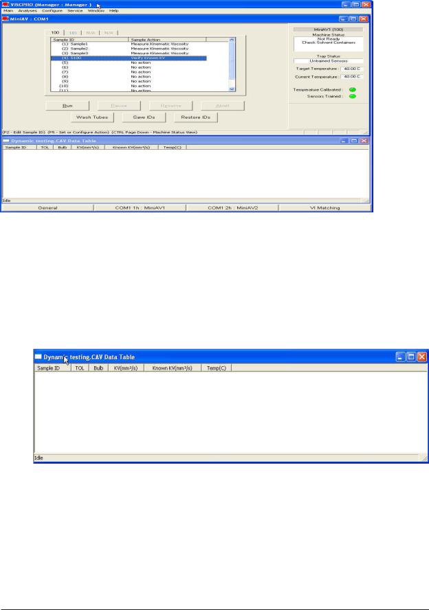
settings. The image below demonstrates a typical screen configuration: |
Title Bar |
|
|
|
|
|
|
|
|
|
||
Menu Bar |
|
|
|
||
|
|
||||
Sample
Input window
Status bar
Analysis
window
Status bar
The VISCPRO® primary display
The VISCPRO® primary display window is framed on the top by the VISCPRO® title bar and menu bar, and on the bottom by the VISCPRO® status bar. The application window can be user-configured to include child windows (Sample Input or Machine Status windows, Analyses) which can be opened and closed independently. The Sample Input window describes your CANNON® instrument and provides controls for running tests. The Analysis window presents data from miniAV-X tests.
CANNON® miniAV-X Automatic Viscometer with VISCPRO® Instruction & Operation Manual Version 1.Ob— March, 2012; CANNON® Instrument Company
2139 High Tech Road • State College, PA 16803 • USA
9
The Sample Input window
NOTE |
If the Sample Input window does not appear when the software loads, click |
|
View Instrument from the Main menu, then click the desired instrument |
|
group (type of instrument, e.g. miniAV-X, CCS, CAV-2100) from the list of |
|
available instruments and click OK. If the Available Instruments list box is |
|
blank, your miniAV-X instrument may not be on-line. Check cable connec- |
|
tions and make certain the unit power switch is ON. |
The Data Table analysis/report window (displays data from completed tests)
Checking configuration
Initial configuration
The installation CD-ROM copy of the SAMPLES.MDB file contains initial factory calibration data unique to that instrument.
CANNON® miniAV-X Automatic Viscometer with VISCPRO® Instruction & Operation Manual Version 1.0b— March, 2012; CANNON® Instrument Company
2139 High Tech Road • State College, PA 16803 • USA

10
NOTE
Configuration protection
If you wish to restore the original configuration, archive your sample data before doing so (see Chapter 13 for information on using the Database Manager software). Then copy the original SAMPLES.MDB file from the CD-ROM to the database directory corresponding to your operating system (see table, previous page).
Follow the procedures in the next several sections of this chapter to verify/edit the instrument and calibration settings to ensure that they conform to the actual characteristics of your CANNON® instrument.
It is not necessary to log in to view current instrument settings. However, to change the configuration settings, you must log in to the security system as a manager. The software is installed with a default Manager account. This account has no password, allowing any operator access to manager-level software functions as long as the password is not activated/changed. If you would like to engage the full-release security options, see Security Options in Chapter 4 for instructions.
Logging in
1.Use your mouse to click Main from the VISCPRO® menu bar.
2.Click Log In from the Main menu options.
3.Click on the  (arrow) on the right side of the User Name: list box to display the list of registered users.
4.Click Manager. Do NOT enter a password unless you have previously set up the Manager account with a password.
5.Click OK. The Log In window will close automatically and you will be logged in as management personnel.
Checking Instrument Settings
1.Use your mouse to click (select) Configure from the VISCPRO® menu bar.
2.Select your instrument from the list of available instruments (there may be only one instrument in the list).
3.Select Instrument Settings from the list of configuration options. The Instrument Settings window will appear.
CANNON® miniAV-X Automatic Viscometer with VISCPRO® Instruction & Operation Manual Version 1.Ob— March, 2012; CANNON® Instrument Company
2139 High Tech Road • State College, PA 16803 • USA

11
You will use the Instrument Settings window (see below) to describe and control miniAV-X instrument operational features. These settings affect the instrument as a whole. Check the instrument settings for your instrument per the instructions below, and make any necessary changes:
The Instrument Settings window
Use the ID field to input instrument identification information using up to 16 alphanumeric characters.
|
The S/N: field (non-editable) indicates the serial number from the label |
|
on the miniAV-X rear service panel. |
Prompt options |
The Prompt for Check Standards options permit you to set a computer- |
|
ized “alarm clock” which will pop up a message reminder to run a check |
|
standard based on the schedule you set with the control. Notice that you |
|
can specify a reminder after “x” number of days and/or “x” number of |
|
samples. Click the check box(es) to enable/disable each reminder. |
|
When you have verified all settings, click OK. |
CANNON® miniAV-X Automatic Viscometer with VISCPRO® Instruction & Operation Manual Version 1.0b— March, 2012; CANNON® Instrument Company
2139 High Tech Road • State College, PA 16803 • USA

12
Viewing/editing setup information
NOTE |
For first-time installation, make certain that the factory-prepared Configu- |
|
|
ration file has been copied to the Default Data directory per instructions |
|
|
on page 7 of manual. If your instrument has already been configured, |
|
|
you can use the instructions in this section of the manual to check or, if |
|
|
necessary, change the instrument settings. |
|
|
1. |
Click Configure from the VISCPRO® menu bar. |
|
2. |
Select your instrument group and instrument from the list of avail- |
|
|
able instruments. |
|
3. |
Select Tray Settings: Tube and Bath from the list of configuration |
|
|
options. The Tray Settings: Tube and Bath window will appear. |
The Tray Settings: Tube and Bath window
The Tray Settings: Tube and Bath window contains setup information for each tube associated with your instrument. On multiple-tube CANNON instruments, you can click on the tube tabs to see the setup information for different tubes.
4.Verify that the tube serial number (Tube S/N) is correct. If it is not, input the correct serial number in the text box. Each tube should have a unique serial number!
5.Verify the presence of calibration values (C and E) for each bulb. If calibration data is not
available, the default values |
Sample calibration constants |
|
are C=1 and E=0. |
||
|
CANNON® miniAV-X Automatic Viscometer with VISCPRO® Instruction & Operation Manual Version 1.Ob— March, 2012; CANNON® Instrument Company
2139 High Tech Road • State College, PA 16803 • USA

13
Manually changing tube calibration constants
NOTE
Procedure
If you discovered any errors in the values of the calibration constants (see previous section), follow the directions in this section to manually correct them using calibration information previously obtained for your unit. If the calibration values are correct, instrument setup is complete.
This procedure for manually entering/changing calibration constants bypasses the normal calibration procedure. To ensure the most accurate viscosity readings, CANNON® Instrument Company recommends that the instrument be calibrated per the calibration procedure outlined in Chapter 3.
1.Log in as a Manager and click Configure from the VISCPRO® menu bar.
2.Select your instrument from the list of available instruments.
3.Select Calibration from the list of configuration options. The Calibration window will appear (see next page).
The Calibration window provides controls for calibrating each bulb of any viscometer associated with your instrument. You can click on the
bulb spin controls  to display current constants and valid check standard data available for calibration of each bulb.
1. Make sure that the spin controls  for Bulb are set to “1”:
This corresponds to the bottom bulb in the tube.
2.Check the values for the calibration constant(s) as they appear at the bottom of the window:
CANNON® miniAV-X Automatic Viscometer with VISCPRO® Instruction & Operation Manual Version 1.0b— March, 2012; CANNON® Instrument Company
2139 High Tech Road • State College, PA 16803 • USA

14
The Calibration window
Compare this value to your archive of the calibration constant data (if available) for bulb 1. The values should be identical.
3.If they are not, place your cursor in the appropriate field, delete the entry, then type the correct values for the constant in the text box.
4.Click Update tube  .
.
5.Use the bulb spin controls  to select the other bulb(s) for which you noted calibration constant errors. Input the correct values for each. Make certain to click Update Tube after you have corrected C and E calibration values for each bulb BEFORE selecting the next bulb.
6.When you have entered corrected constant values for each bulb on both tubes, click  to exit the Calibration window.
You have verified the software configuration of VISCPRO®. To test samples with your instrument, follow the instructions in Chapter 2. For additional details regarding operating procedures for your instrument or software, consult the appropriate section of this manual.
Checking Wash and Advanced Settings
To check Wash Settings for your miniAV-X instrument, click Configure from the VISCPRO menu options and select the desired instrument. Then click Tray Settings: Wash. The Tray Settings: Wash window will appear.
CANNON® miniAV-X Automatic Viscometer with VISCPRO® Instruction & Operation Manual Version 1.Ob— March, 2012; CANNON® Instrument Company
2139 High Tech Road • State College, PA 16803 • USA

15
Compare the values in the Tray Settings: Wash window with your archived values and make any necessary changes; then click OK.
To check Advanced Settings for your miniAV-X instrument, click Configure from the VISCPRO menu options and select the desired instrument. Then click Tray Settings: Advanced. The Tray Settings: Advanced window will appear.
CANNON® miniAV-X Automatic Viscometer with VISCPRO® Instruction & Operation Manual Version 1.0b— March, 2012; CANNON® Instrument Company
2139 High Tech Road • State College, PA 16803 • USA

16
Compare the values in the Tray Settings: Advanced window with your archived values and make any necessary changes; then click OK.
Preparing the miniAV-X for testing
Inserting the miniAV-X temperature probes/reference thermometer
Inserting the probes |
The temperature probe and thermal fuse probe are semi-permanently |
|
installed. Initial installation or replacement requires removal of the top |
|
cover of the bath unit. The probes are inserted through the narrow |
|
aperture on the top bath flange and held in place with a sliding metal |
|
plate (friction fitting) secured with a thumbscrew. |
miniAV-X top bath flange |
|
Inserting the thermometer The ASTM reference thermometer/adapter assembly can be inserted through the grommet in the bath top cover and through the larger circular aperture on the top bath flange (see photo image above). The assembly includes a stop collar with set screw that can be adjusted to vary the thermometer height.
CAUTION Do NOT insert a reference thermometer while the miniAV-X bath impeller is operating, as damage to the thermometer and/or viscometer tube may result. Make certain to insert the appropriate reference thermometer for the current bath temperature! Use appropriate safety procedures when handling the thermometer, as it contains mercury.
CANNON® miniAV-X Automatic Viscometer with VISCPRO® Instruction & Operation Manual Version 1.Ob— March, 2012; CANNON® Instrument Company
2139 High Tech Road • State College, PA 16803 • USA

17
NOTE |
If using the ERTCO-HART 12” temperature probe in place of the ASTM |
|
thermometer, it will be necessary to remove the grommet in the bath top |
|
cover prior to inserting the probe. The probe will seat properly in the |
|
aperture left by the grommet removal. |
Adjusting Vacuum/Pressure settings
To adjust the vacuum setting for the miniAV-X, click Service from the VISCPRO menu options and select the desired instrument group and instrument. Then click Adjust Vacuum/Pressure to open the Adjust Vacuum/Pressure window.
Select the desired adjustment (vacuum or pressure) and then follow the screen prompts to complete the adjustment procedure, using the appropriate controls on the instrument side (“ear”) panel. The prompts will display recommended vacuum/pressure settings and will also indicate how adjustments may be made to alter the settings.
Setting bath temperature


 WARNING Prior to setting the bath temperature, ensure that the reference thermometer in the bath is suitable for the desired temperature range. If not, remove thermometer from the bath. If the bath temperature rises above the range of the thermometer, it may be damaged. Mercury thermometers pose particular problems, since mercury from a damaged thermo-meter may circulate with bath fluid.
To set the temperature:
1.Load the VISCPRO® software and click Configuration.
2.Select the miniAV-X from the list of available instruments and click
Tray Settings: Tube and Bath.
CANNON® miniAV-X Automatic Viscometer with VISCPRO® Instruction & Operation Manual Version 1.0b— March, 2012; CANNON® Instrument Company
2139 High Tech Road • State College, PA 16803 • USA

18
|
3. Select the desired unit of temperature measurement (°C or °F). |
|
4. Type the desired temperature in the Bath Temp: field. Acceptable |
|
values are any numbers between 20°C and 100°C. If necessary, you |
|
may use the decimal point key to input temperature to the nearest |
|
0.01°C. Press OK to save the temperature setting. |
NOTES |
The miniAV-X will not allow sample testing until the instrument has |
|
equilibrated temperature at the test temperature. |
|
To cancel temperature selection before completing the procedure, click |
|
Cancel. |
|
After the target temperature has been set, the miniAV-X bath temperature |
|
will be adjusted to the target temperature and the bath will equilibrate at |
|
the test temperature. The VISCPRO II software always displays the |
|
current and target bath temperature in the Sample Input window. |
Checking wash functions
To ensure function of the solvent wash system, follow the procedure below:
1.Place an empty vial in the sample tray position 1.
2.Select Wash viscometer tube to open the Wash viscometer tube window.
3.Click Begin Wash to initiate the wash cycle. The Status: indicator will display and update current actions.
CANNON® miniAV-X Automatic Viscometer with VISCPRO® Instruction & Operation Manual Version 1.Ob— March, 2012; CANNON® Instrument Company
2139 High Tech Road • State College, PA 16803 • USA

19
Bypass .... option |
To begin washing an evacuated sample cup, click the option box to make |
|
certain that the Bypass initial cup evacuation option is selected. Do not |
|
use this option with a filled cup or the cup will overflow. |
|
4. When the Wash cycle has been completed, click Done to exit the |
|
Wash viscometer tube window. |
NOTES |
The Wash operation cannot be executed if the tube is currently running a |
|
sample. To terminate the Wash cycle at any time, click Abort Wash. |
CAUTION |
The Wash viscometer tube function overrides automatic miniAV-X |
|
software operations. Verify that the tubes are clean and dry before |
|
initiating computer-controlled sample testing. |
Training tube sensors
miniAV-X tube sensors must be trained in order for the instrument to properly perform test functions. To train miniAV-X sensors, follow the instructions in Chapter 3.
NOTES |
The temperature should be calibrated prior to training the miniAV-X tube |
|
sensors. |
Calibrating the miniAV-X
To ensure accurate test results, your instrument may need to be calibrated. If necessary, follow the instructions in Chapter 3 to calibrate your miniAV-X temperature probe and viscometer tube.
Notes on computer-directed miniAV-X operation
A computer is required for miniAV-X operation. The computer provides for automatic control of miniAV-X functions using the VISCPRO® controlling software. Computer control permits data entry of up to ten different sample IDs. Each of the identified samples can then be tested with the miniAV-X instrument.
Reporting data |
Test data for the samples is automatically saved to the VISCPRO® |
|
database for future reporting/data collection. Additionally, several reports |
|
(analyses) may be used to calculate and display kinematic viscosity and |
|
viscosity index (VI) values. See the chapters on VISCPRO® analyses for |
|
further information. |
|
All analyses provide a dynamic reporting option which can dynamically |
|
display and transmit test results as testing is completed. Data can be sent |
|
to your computer screen, printer, and/or serial port for in-house data |
|
collection. See Chapter 6 for more information on configuring analyses. |
CANNON® miniAV-X Automatic Viscometer with VISCPRO® Instruction & Operation Manual Version 1.0b— March, 2012; CANNON® Instrument Company
2139 High Tech Road • State College, PA 16803 • USA

20
This page intentionally left blank.
CANNON® miniAV®-X Automatic Viscometer with VISCPRO® Instruction & Operation Manual Version 1.0— February, 2008; CANNON® Instrument Company
2139 High Tech Road • State College, PA 16803 • USA

21
CHAPTER |
|
2 |
TESTING SAMPLES WITH THE |
|
miniAV-X AUTOMATIC VISCOMETER |
This chapter of the manual will provide information on testing samples using the miniAV-X. Observe the safety cautions noted in the introductory chapter when operating equipment. The miniAV-X should only be operated by qualified personnel.
Turning on the miniAV-X
|
Turn on the miniAV-X Bath Unit using the power switch on the power |
|
supply unit. |
Testing samples |
|
Loading software |
1. Turn on the computer and load the miniAV-X software by double- |
|
clicking the VISCPRO® II icon on the Desktop. |
NOTES |
If the software is already loaded, use your computer mouse to click Main |
|
from the menu bar and click Poll for Instruments from the Main menu |
|
options. This will establish communications between the computer and |
|
the on-line instrument. |
|
Permit the bath to stabilize at test temperature before testing samples. |
|
2. Pour sample material into the glass |
|
vial(s). For 20 mL vials, fill only half |
|
full, as the viscometer tube will |
|
displace sample in the vial. Approxi- |
|
mately 10 mL of sample should be |
|
sufficient for testing in either bulb of |
|
the viscometer. |
NOTES |
Do not overfill the vials. Sample overflow |
|
may create problems for the tube |
|
cleaning cycle. |
You should periodically test calibration check standards per your established laboratory procedures. Recalibrate the miniAV-X (see Chapter 3, Calibration) if result variance warrants.
3. Place the sample vials in the |
|
carousel. |
Filled sample vial |
|
CANNON® miniAV®-X Automatic Viscometer with VISCPRO® Instruction & Operation Manual Version 1.0— February, 2008; CANNON® Instrument Company
2139 High Tech Road • State College, PA 16803 • USA
22
4Check the thermometer in the temperature bath to make sure the bath is holding the proper temperature. If necessary, calibrate the miniAV- X temperature control probe using the temperature calibration procedure in Chapter 3.
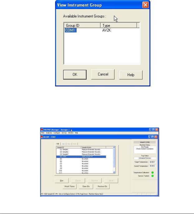
5.Open the View Instrument Group window (if it is not already open) by clicking View Instrument from the Main menu and selecting the desired instrument group from the list box (see Chapter 4 for more information).
The View Instrument Group window
6.Select the desired group ID and click OK to display the Sample Input View.
The Sample Input window (miniAV-X four--bath system)
CANNON® miniAV®-X Automatic Viscometer with VISCPRO® Instruction & Operation Manual Version 1.0— February, 2008; CANNON® Instrument Company
2139 High Tech Road • State College, PA 16803 • USA
23
Then click the Tray tab corresponding with the desired miniAV-X.
7. Double-click on Sample ID (1) with the left mouse button to access
|
the sample ID data entry field (or press 2). |
|
8. Enter sample ID information in the sample list box using your |
|
computer keyboard. After you have typed the sample ID, press the |
|
T key to complete the entry and move the cursor to the next |
|
Sample ID field. Or press R to complete the entry. |
NOTE |
Once sample information is entered, the software automatically assigns |
|
a sample action, Measure Sample Viscosity, for the sample. If you do not |
|
enter a sample ID, the sample is automatically labeled Unknown. |
|
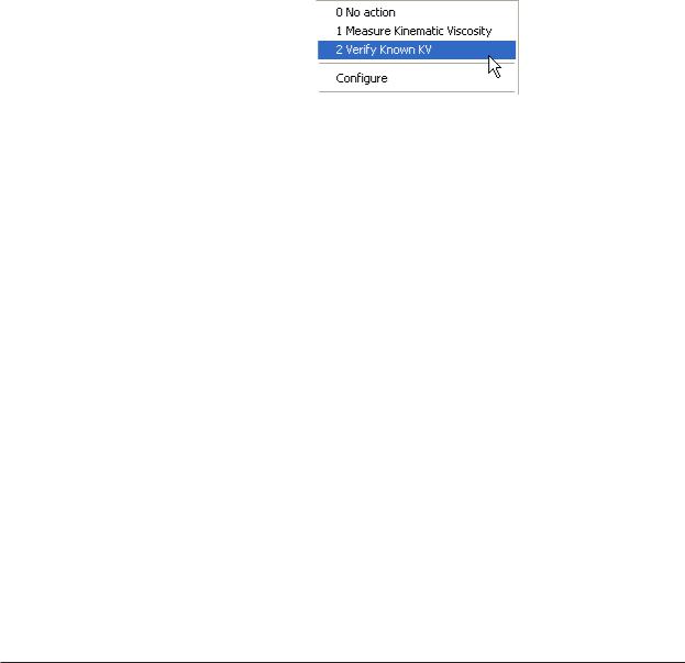
To select or change a sample action, highlight the appropriate Sample |
|
ID(s) using the mouse or arrow keys, then click the RIGHT mouse |
|
button to access sample action options: |
|
|
Then you may select the desired action by highlighting it with the |
|
|
mouse and clicking the left mouse button. |
NOTE |
For additional information on software data entry features, including |
|
|
multiple sample selection and cut & paste options, see Testing |
|
|
samples—software options in Chapter 4. |
|
Running check standards |
|
If Verify Known KV is selected as the test option for a sample, the |
|
|
Viscosity Action window will open automatically. Enter the neces- |
|
|
sary check standard data, including the Check Standard viscosity |
|
|
from the standard bottle, and click OK to complete data entry. To |
|
|
revise or confirm standard data, right-click on the desired sample ID |
|
|
from the list box and select Configure from the popup menu choices. |
NOTE |
See Chapter 4 for additional information on the Viscosity Action window. |
|
|
9. |
Continue entering sample information for all desired trays. When |
|
|
sample ID data entry is complete, check the Tray Status window to |
|
|
verify that all trays are ready for testing. |
|
10. |
Click on the RUN button at the bottom of the Sample Input win- |
|
|
dow. The Select Trays window will open if more than one miniAV- |
|
|
X instrument is online. |
|
11. |
If necessary, click on the check box(es) to select the desired prepared |
|
|
“tray” (sample sequence) for automatic testing. For the miniAV-X, a |
|
|
tray corresponds to the miniAV-X instrument. Then click OK to |
|
|
begin the miniAV-X test(s). |
CANNON® miniAV-X Automatic Viscometer with VISCPRO® Instruction & Operation Manual Version 1.0b— March, 2012; CANNON® Instrument Company
2139 High Tech Road • State College, PA 16803 • USA
24
Pausing a test
|
To temporarily halt testing for a given tube/sample, click the Pause |
|
button from the Sample Input window. Then select the desired tray |
|
(miniAV-X instrument) and pause action(s) from the Select Trays |
|
window (Pause Now will immediately pause test actions; Pause after |
|
current sample will pause testing after the current test is complete). |
|
Click OK to pause testing for the selected tray(s). |
NOTE |
If the test was paused prior to the initiation of the Wash cycle, drop time |
|
data for that sample will be discarded. |
Resuming a test
|
To resume test actions for paused trays, click the Resume button from |
|
the Sample Input window. Then select the desired trays from the Select |
|
Trays window. Click OK to resume sample testing (see note above). |
Aborting a test |
|
|
To permanently halt testing for a given tube/tray, click the Abort button |
|
from the Sample Input window. Then select the desired trays from the |
|
Select Trays window. Click OK to abort testing for the selected tray. |
NOTE |
Aborting a test clears all sample test information for that tray. If test |
|
actions are aborted, it is the responsibility of the user to restore the |
|
instrument to a safe state before running tests (see Service menu |
|
options in chapter 4 for more information on tube washing and drying). |
Concluding a test |
|
|
After automatic testing has been completed, make certain that: |
|
1. the sample vial carrier is in the lowered position. |
 CAUTION Use appropriate procedures when handling warm sample vials to avoid
 the possibility of burns.
2.the Machine Status (as indicated in the VISCPRO® Sample Input Machine Status window), is READY, and
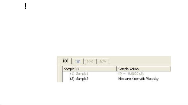
3.the Tray Status for the tube, as indicated in the VISCPRO® Sample Input Tray Status window, is IDLE. Kinematic viscosity for any tested samples will be displayed in the Sample Action column in the action list for the selected tube.
NOTE
CANNON® miniAV-X Automatic Viscometer with VISCPRO® Instruction & Operation Manual Version 1.Ob— March, 2012; CANNON® Instrument Company
2139 High Tech Road • State College, PA 16803 • USA
 Loading...