


i
|
|
|
|
|
|
CONTENTS |
||
1 |
INTRODUCTION |
1 |
|
|
|
|
||
|
Instrumentoverview .............................................................................................................. |
|
|
|
2 |
|||
|
Instrumentspecifications ....................................................................................................... |
|
|
|
3 |
|||
|
Safety warnings .................................................................................................................... |
|
|
|
3 |
|||
2 |
UNPACKING AND ASSEMBLY |
5 |
|
|||||
|
Unpacking the CMRV-5000 ................................................................................................. |
|
|
|
|
5 |
||
|
User-Supplied Equipment ..................................................................................................... |
|
|
|
6 |
|||
3 |
CMRV-5000 APPARATUS DESCRIPTION |
7 |
||||||
|
CMRV-5000 unit/accessories ............................................................................................... |
|
|
|
|
7 |
||
|
Front panel operations .......................................................................................................... |
|
|
|
9 |
|||
4 |
SETUP |
11 |
|
|
|
|
|
|
|
Physical placement .............................................................................................................. |
|
|
|
11 |
|||
|
Electrical /serial connections ................................................................................................ |
|
|
|
11 |
|||
|
Pulley-wheelinstallation ...................................................................................................... |
|
|
|
13 |
|||
|
Firmware installation notes .................................................................................................. |
|
|
|
14 |
|||
|
Setting the CMRV instrument address ................................................................................. |
|
|
|
14 |
|||
|
Gas Purge option installation ............................................................................................... |
|
|
|
14 |
|||
|
Cleaningtheinstrumenthousing ........................................................................................... |
|
|
|
15 |
|||
5 |
VISCPRO® INSTALLATION |
|
|
|
17 |
|
|
|
|
VISCPRO® for Windows® XP® .......................................................................................... |
|
|
|
|
17 |
||
|
Installing VISCPRO® software ............................................................................................ |
|
|
|
17 |
|||
|
Computer requirements ........................................................................................... |
|
|
|
17 |
|||
|
Windows® XP® installation ...................................................................................... |
|
|
|
17 |
|||
|
Installationactions ................................................................................................... |
|
|
|
17 |
|||
|
Running the software ........................................................................................................... |
|
|
|
18 |
|||
|
Loading software .................................................................................................... |
|
|
|
18 |
|||
|
Displaying the InstrumentView window ................................................................... |
18 |
||||||
|
Viewing report data ................................................................................................ |
|
|
|
20 |
|||
|
Loggingin ............................................................................................................... |
|
|
|
21 |
|||
|
Checking Instrument Settings .................................................................................. |
|
|
|
21 |
|||
|
Setting multiple CMRV instrument addresses ....................................................................... |
23 |
||||||
|
Security options .................................................................................................................. |
|
|
|
23 |
|||
|
Initial security setup ................................................................................................. |
|
|
|
24 |
|||
CANNON® Mini-Rotary Viscometer CMRV-5000 Instruction & Operation Manual Version 1.0b—March, 2011; CANNON® Instrument Company
2139 High Tech Road • State College, PA • 16803 • USA

ii
6
PREPARING FOR CMRV TESTING/CALIBRATION |
27 |
Cleaningcycle .................................................................................................................... |
27 |
Cleaning procedure ................................................................................................. |
27 |
Inserting rotors ....................................................................................................... |
30 |
7 |
CALIBRATING THE CMRV TEMPERATURE PROBE |
31 |
|
Probe calibration procedure .................................................................................... |
31 |
|
Manual restoration of voltage and offset data ........................................................... |
33 |
8 |
CALIBRATING THE CMRV CELLS |
35 |
|
Calibration theory ............................................................................................................... |
35 |
|
Cell calibration procedure ................................................................................................... |
36 |
|
Preparing the cells ................................................................................................... |
36 |
|
Cell calibration test procedure ................................................................................. |
38 |
9 |
USING THE CMRV SOFTWARE |
41 |
|
VISCPRO® generic instrument interface .............................................................................. |
41 |
|
Main options .......................................................................................................... |
42 |
|
Security options ...................................................................................................... |
44 |
|
Initial security setup ................................................................................................. |
45 |
|
Print/Print setup options .......................................................................................... |
46 |
|
Analyses options ................................................................................................................. |
46 |
|
Analysis types ......................................................................................................... |
46 |
|
Analyses menu options ............................................................................................ |
47 |
|
Window options ................................................................................................................. |
48 |
|
CMRV module menu options .............................................................................................. |
49 |
|
Configure options ................................................................................................... |
49 |
|
Print Instrument and Tray Settings ........................................................................... |
49 |
|
InstrumentSettings .................................................................................................. |
49 |
|
ProfileDesigner ...................................................................................................... |
50 |
|
View Cell Constants ............................................................................................... |
50 |
|
Savingaconfiguration ............................................................................................. |
51 |
|
Restoring instrument settings from a saved configuration ........................................... |
51 |
|
Calibrate Cell Constants ......................................................................................... |
52 |
|
Service menu options .......................................................................................................... |
54 |
CANNON® Mini-Rotary Viscometer CMRV-5000 Instruction & Operation Manual Version 1.0b—March, 2011; CANNON® Instrument Company
2139 High Tech Road • State College, PA • 16803 • USA

iii
10 SUMMARY OF TEST PROCEDURE |
55 |
||
|
ASTM D 4684 method ...................................................................................................... |
|
55 |
|
ASTM D 3829 method ...................................................................................................... |
56 |
|
|
ASTM D 6821 method ...................................................................................................... |
56 |
|
|
ASTM D 6896 method ...................................................................................................... |
57 |
|
|
SAE J300 notes ................................................................................................................. |
57 |
|
|
Delayed start option ............................................................................................................ |
57 |
|
11 RUNNING PROFILES |
59 |
||
|
Starting a profile ................................................................................................................. |
|
61 |
|
Profile operation notes ........................................................................................................ |
61 |
|
|
Adjusting temperature at the end of a profile ............................................................ |
62 |
|
|
Displaying a profile graph .................................................................................................... |
63 |
|
|
Printing a profile graph ........................................................................................................ |
64 |
|
|
Exporting time/temperature profile data ............................................................................... |
64 |
|
12 MEASURING YIELD STRESS AND VISCOSITY |
65 |
||
|
Measuring yield stress ......................................................................................................... |
|
65 |
|
Notes on yield stress testing ................................................................................................ |
67 |
|
|
Measuring apparent viscosity .............................................................................................. |
67 |
|
|
Notes on viscosity testing .................................................................................................... |
68 |
|
|
Printing yield stress/viscosity test results ............................................................................... |
69 |
|
|
Exporting yield stress/viscosity data ..................................................................................... |
69 |
|
13 ANALYSIS CONFIGURATION OPTIONS |
71 |
|
|
|
Creating an analysis ............................................................................................................ |
|
71 |
|
Sorting analysis data ........................................................................................................... |
73 |
|
|
Using the date filter ............................................................................................................. |
73 |
|
|
Using the sample/error filter ................................................................................................. |
74 |
|
|
Using the report/port output filter ......................................................................................... |
75 |
|
|
Reconfiguring a displayed analysis ....................................................................................... |
75 |
|
|
Resizingtablecolumns ........................................................................................................ |
76 |
|
|
Saving a current analysis configuration ................................................................................. |
76 |
|
|
Deletingananalysisconfiguration ......................................................................................... |
76 |
|
|
Printingananalysis .............................................................................................................. |
76 |
|
|
Keystrokes for selecting data for printing ................................................................. |
77 |
|
|
Exporting analysis data ........................................................................................................ |
78 |
|
|
Exporting time and temperature data ................................................................................... |
78 |
|
CANNON® Mini-Rotary Viscometer CMRV-5000 Instruction & Operation Manual Version 1.0b—March, 2011; CANNON® Instrument Company
2139 High Tech Road • State College, PA • 16803 • USA

iv
14 DESIGNING CUSTOMIZED PROFILES |
79 |
CoolingProfiles .................................................................................................................. |
79 |
The Profile Designer ........................................................................................................... |
79 |
Opening the Profile Designer ................................................................................... |
80 |
Interface options ..................................................................................................... |
81 |
Managingprofiles ................................................................................................... |
81 |
Using the Profile Editor ........................................................................................... |
82 |
Editingpoints .......................................................................................................... |
83 |
Deletingpoints ........................................................................................................ |
83 |
Coolingprofilelimitations .................................................................................................... |
84 |
Profile Designer test parameters .......................................................................................... |
84 |
Changing test parameters ....................................................................................... |
85 |
15
16
17
18
MRV DATA TABLE ANALYSIS |
87 |
Configuring the MRV DataTable ............................................................................ |
88 |
ERROR LOG TABLE ANALYSIS |
91 |
Configuring the Error Log analysis ........................................................................... |
91 |
EXPORT ANALYSES |
95 |
Configuring the Port Export analyses ....................................................................... |
96 |
USING THE DATABASE MANAGER |
101 |
Archiving old data ................................................................................................. |
102 |
Changing the database directory ............................................................................ |
102 |
Importing archived data ........................................................................................ |
103 |
Repairing/compacting the database ........................................................................ |
103 |
Exit ...................................................................................................................... |
103 |
19 WARRANTY/RETURN INFORMATION |
105 |
Products limited warranty .................................................................................................. |
105 |
Reagent and chemical warranty ......................................................................................... |
105 |
CANNON® Mini-Rotary Viscometer CMRV-5000 Instruction & Operation Manual Version 1.0b—March, 2011; CANNON® Instrument Company
2139 High Tech Road • State College, PA • 16803 • USA

v
A |
APPENDIX A — TROUBLESHOOTING |
107 |
|
|
||||
|
Instrument status window not updating |
.................................................................. |
|
|
107 |
|||
|
The CMRV is not heating properly ........................................................................ |
|
|
107 |
||||
|
TheYield/Viscosity lights on the CMRV . .Controller front panel are blinking rapidly 107 |
|||||||
|
CMRV cooling/temperature control problems ........................................................ |
107 |
||||||
|
Yield stress or viscosity test results inconsistent. ..................................................... |
107 |
||||||
|
Test icons "greyed out"--unable to initiate .........................................viscosity tests |
107 |
||||||
B |
APPENDIX B — REPLACEMENT PARTS LIST |
109 |
|
|||||
C |
APPENDIX C — THERMOMETRY |
|
|
111 |
|
|
|
|
|
Kinematic viscosity and temperature ................................................................................... |
|
|
|
111 |
|||
|
ASTM thermometer tables ................................................................................................ |
|
|
112 |
||||
|
ASTM D 445 — Checking the ice point ........................................................................... |
|
|
113 |
||||
|
NBS Monograph150: Joining separated mercury .................................................columns |
115 |
||||||
D |
APPENDIX D — MULTI-UNIT CONFIGURATION |
117 |
|
|||||
|
Introduction ...................................................................................................................... |
|
|
117 |
||||
|
Procedure ........................................................................................................................ |
|
|
117 |
||||
I |
INDEX |
119 |
|
|
|
|
|
|
CANNON® Mini-Rotary Viscometer CMRV-5000 Instruction & Operation Manual Version 1.0b—March, 2011; CANNON® Instrument Company
2139 High Tech Road • State College, PA • 16803 • USA

vi
This page intentionally left blank.
CANNON® Mini-Rotary Viscometer CMRV-5000 Instruction & Operation Manual Version 1.0b—March, 2011; CANNON® Instrument Company
2139 High Tech Road • State College, PA • 16803 • USA

CHAPTER
1
Purpose of the manual
Instrument utility
NOTE
Improvements
The CMRV-5000
1
INTRODUCTION
This manual has been written to provide the information necessary for proper installation, operation, and maintenance of the CANNON® MiniRotary Viscometer (CMRV-5000).
The CANNON® Mini-Rotary Viscometer is used to measure the apparent viscosity and yield stress of engine oils and drive line lubricants within the temperature range of -10°C to -40°C using ASTM test methods D 4684, D 3829, D6821 and D 6896. ASTM test method D 4684 is required by the Society of Automotive Engineers (SAE) Engine Oil Viscosity Classification SAE J300.
The CMRV-5000 capabilities have been tailored to the requirements of the current ASTM methods cited above. For this reason, the instrument may not be suitable for some general-purpose viscometry applications. Consult with CANNON® Customer Service before testing with materials and/or methodology at significant variance with ASTM D 4684, ASTM D 3829, ASTM D 6821 or ASTM D 6896.
The CMRV-5000 is a state-of-the-art system offering many superior features including:
New Method compatibility
The CMRV-5000 is fully compatible with ASTM D 6821, the new Drive Line Lubricants test method. The CMRV-5000 is fully compatible with ASTM D 6896, a new method for testing used diesel oils.
Improved insulation for temperature control
The CMRV-5000 instrument features a redesigned housing and accessory rotor collars to enhance insulating characteristics and precision.
Software library of temperature profiles (cooling profiles)
Predefined cooling profiles that comply with methods ASTM D 3829, ASTM D 4684, ASTM D 6821 and ASTM D 6896 are supplied with the CMRV software. The user may also create custom cooling profiles with the Profile Designer.
VISCPRO® software with Profile Designer
The VISCPRO® software for Windows® XP®, features a Profile Designer for creating unique cooling profiles.
CANNON® Mini-Rotary Viscometer CMRV-5000 Instruction & Operation Manual Version 1.0b—August, 2011; CANNON® Instrument Company
2139 High Tech Road • State College, PA • 16803 • USA

2
Networking capability for multiple instruments
The VISCPRO® software can control/monitor up to four CMRV instruments with one computer via RS-485 serial connections. See APPENDIX D for more information.
Instrument overview
|
The CANNON® Mini-Rotary Viscometer is designed for precision |
|
control of temperature over time, enabling accurate yield stress and |
|
viscosity measurement of oil samples in conformance with ASTM D |
|
3829, ASTM D 4684, ASTM D 6821 and ASTM D 6896 test methods. |
Test procedure |
Oil samples placed in the CMRV-5000 viscometric cells are heated and |
|
cooled at a predetermined rate according to a user-specified cooling |
|
profile. The cooling profile parameters are downloaded to the CMRV- |
|
5000 onboard memory via a serial interface with the host computer. The |
|
CMRV-5000 then uses this profile to control the rate of temperature |
|
change, independent of the host computer. |
|
All three methods specify that the samples be initially heated to ensure |
|
that all components of the sample are released into solution. The samples |
|
are then slowly cooled to the test temperature using the user-selected |
|
temperature profile and maintained at test temperature for a specified |
|
soak period. Following the soak period, apparent viscosity (and yield |
|
stress if applicable) for each sample is determined by applying a constant |
|
torque to, and measuring the rotational speed of, a cylindrical rotor |
|
which has been immersed in the sample. |
|
The time required for completion of the ASTM D 3829 test cycle is |
|
approximately 19 hours. The time required for completion of the ASTM |
|
D 4684 (TP-1, two-day) test is 45½ to 53½ hours. The time required for |
|
completion of the ASTM D 6821 test cycle is approximately 18 hours. |
|
The time required for completion of the ASTM D 6986 test cycle is |
|
approximately 43½ to 53½ hours. |
NOTE |
See Chapter 10 for additional information on the ASTM procedures. |
CANNON® Mini-Rotary Viscometer CMRV-5000 Instruction & Operation Manual Version 1.0b—August, 2011; CANNON® Instrument Company
2139 High Tech Road • State College, PA • 16803 • USA

3
Instrument specifications
|
CMRV-5000 SERIES SPECIFICATIONS |
|
|
|
|
Dimensions |
284 mm wide × 396 mm deep × 617 mm high* (11.2 × 15.6 × 24.3") |
|
|
|
|
Weight |
23 kg (50 lbs) |
|
|
|
|
Shipping Weight |
32 kg (70 lbs) |
|
|
|
|
Operational temperature |
80°C to -40°C |
|
|
|
|
Operating Conditions |
15°C-30°C, 10%-90% RH non-condensing; Installation category II |
|
|
Pollution degree 2 |
|
|
|
|
Fuse Rating |
M 5A 250V; 1¼" × ¼" |
|
|
|
|
Compliance |
EMC directive (89/336/EEC); Low voltage directive (73/23/EEC) |
|
|
HI-POT (1900 VDC, 60 sec.) |
|
|
|
|
Electrical Requirements |
CMRV Block Assembly |
CMRV Block Assembly |
|
115V AC ± 10%; 50/60 Hz, 600 watts |
230 AC ± 10%; 50/60 Hz, 600 watts |
|
Use only the approved power cord |
Use only the approved power cord |
|
supplied with your unit. |
supplied with your unit. |
|
|
|
Catalog Number |
115V unit: 9728-R26 |
230V unit: 9728-R27 |
|
|
|
*Additional height clearance required for insertion of thermometer
Safety warnings
Please observe the following safety procedures and notices for proper operation of your CMRV-5000 unit:
•Make sure that your unit is operated only by qualified personnel
•Make sure that you read and understand all operating instructions and safety precautions listed in this manual before installing or operating your unit. If you have questions regarding instrument operation or documentation, contact CANNON® Instrument Company.
•Deviation from the installation, operation or maintenance procedures described in this manual may result in a hazardous situation and may void the manufacturer's warranty.
•Transport the unit with care. Sudden jolts or drops may cause damage to components.
•Observe all warning labels.
•Never remove warning labels.
•Never operate damaged or leaking equipment.
•Always turn off the unit and disconnect the mains cable from the power source before performing service or maintenance procedures, or before moving the unit.
•Always remove sample from the cells before moving the unit.
•Never operate the equipment with damaged mains power cables.
•Refer all service and repairs to qualified personnel.
CANNON® Mini-Rotary Viscometer CMRV-5000 Instruction & Operation Manual Version 1.0b—August, 2011; CANNON® Instrument Company
2139 High Tech Road • State College, PA • 16803 • USA

4
General Caution
Hot Surface Caution
Protective Conductor


 WARNING
AC Power Input Symbol
( O )
Supply OFF Symbol
In addition to the warnings previously listed, additional cautions are posted throughout the manual. These warnings may be designated by an appropriate symbol inside an equilateral triangle. General cautions are indicated with an exclamation point (see diagram, left). Read and follow these important instructions. Failure to observe these instructions can result in permanent damage to the unit, significant property damage, and personal injury.
Hot surface cautions (see diagram, left) may be attached on or near hot surfaces of the CMRV-5000. Avoid touching these surfaces when running profiles at temperatures above 50°C.
The Protective Conductor Terminal symbol is used to indicate required ground connections for your instrument electrical supply.
When supplying power to this instrument, connect the protective ground (earth) terminals of the instrument to the protective conductor of the (supplied) line (MAINS) power cord. The main plug for the power cord should only be inserted in a socket outlet (receptacle) provided with a protective ground (earth) contact. Do not use an extension cord (power cable) without a protective conductor (grounding).
The ~MAINS symbol indicates instructions or connections for the AC Controller. The AC Power input must match the electrical specifications listed on the label on the rear panel of the instrument. The supplied AC Mains power cord must be attached to the connector labelled ~MAINS. This connection serves as a means of disconnect and should be readily accessible.
The (O) symbol indicates the OFF position for the electrical switches for your unit (AC Mains or accessories).
CANNON® Mini-Rotary Viscometer CMRV-5000 Instruction & Operation Manual Version 1.0b—August, 2011; CANNON® Instrument Company
2139 High Tech Road • State College, PA • 16803 • USA
5
CHAPTER |
|
2 |
UNPACKING AND ASSEMBLY |
Unpacking the CMRV-5000
CAUTION |
Some CMRV components are quite heavy. To avoid injury, obtain neces- |
|
|
sary assistance when lifting and moving shipping cartons and heavier |
|
|
unpacked components. |
|
|
|
Remove all components from the shipping container(s). |
|
|
Remove shipping screws from both fans. |
|
|
Remove any and all packing materials (styrofoam, etc.) from the |
|
|
components. |
|
|
Verify reception of shipped materials by comparing equipment items |
|
|
with packing/parts list(s). Report missing items to CANNON® Instru- |
|
|
ment Company immediately. |
|
|
Inspect each component for signs for damage. Report damages to the |
|
|
shipper and to the CANNON® Instrument Company immediately. |
Damaged items |
Retain all packing materials until the instrument is connected and |
|
|
functioning properly. If any component(s) must be returned to |
|
|
CANNON® Instrument Company, the damaged item(s) should be repack- |
|
|
aged in the original shipping container. Refer to Chapter 19 of this |
|
|
manual for instructions on returning defective equipment. Customers |
|
|
outside the United States should contact the local CANNON® agent for |
|
|
procedures on returning products to CANNON® . |
|
System components |
Before beginning assembly, please verify that all components listed on |
|
|
the packing slip are present, including: |
|
|
|
CMRV-5000 Controller (power supply and controlling electronics) |
|
|
CMRV-5000 head unit (thermostated block with heating/cooling units) |
|
|
Main power cord |
|
|
Pulley-wheel assembly |
|
|
5 matched cells/rotors |
|
|
5 rings and threads |
|
|
RS-232 interface cable |
|
|
Small uncalibrated thermometer (0°C to +105°C) |
|
|
Large calibrated ASTM thermometer (-46°C to +30°C) |
|
|
3k-ohm temperature probe |
|
|
CD-ROM with VISCPRO® software for Windows® XP® |
CANNON® Mini-Rotary Viscometer CMRV-5000 Instruction & Operation Manual Version 1.0b—August, 2011; CANNON® Instrument Company
2139 High Tech Road • State College, PA • 16803 • USA

6
Set of weights:
One 150-gram weight • One hook-cage • Nine additional weights
1 Bottle of N105B with test sample and data sheet
1 Tube thermal paste (for mounting temperature probe)
Plexiglas® Top Cover
Instruction & Operation Manual
5 rotor bearing pins
5 rotor locking pins
Cell holder
Optional rotor stand and drain pan set
User-Supplied Equipment
|
The user must supply an electrical power source matching the electrical |
|
|
requirements indicated on the rear panel of the CMRV-5000 Controller. |
|
Computer |
An IBM-compatible computer with the Windows® XP® operating system |
|
|
(see computer specifications sheet included with your instrument) and |
|
|
printer are also required. |
|
Cleaning supplies |
The following items are required for regular cleaning of the viscometer |
|
|
cells between tests: |
|
|
|
oil solvent |
|
|
acetone |
|
suitable solvent-resistant container for placing/cleaning rotors |
|
|
two plastic squeeze bottles, each with an extension long enough to |
|
|
|
direct oil solvent and acetone directly into the viscometer cells |
CANNON® Mini-Rotary Viscometer CMRV-5000 Instruction & Operation Manual Version 1.0b—August, 2011; CANNON® Instrument Company
2139 High Tech Road • State College, PA • 16803 • USA
7
CHAPTER |
|
3 |
CMRV-5000 APPARATUS |
|
DESCRIPTION |
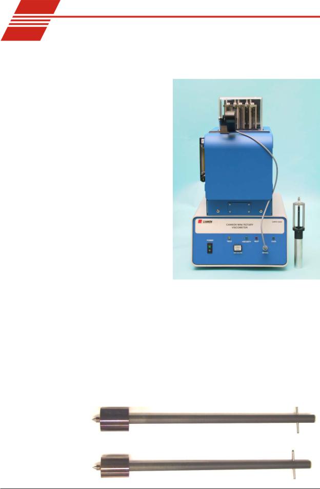
CMRV-5000 unit/accessories
|
The CMRV-5000 unit |
|
|
is comprised of a |
|
|
head unit and Con- |
|
|
troller. The head unit |
|
|
contains an alumi- |
|
|
num block with a |
|
|
heater for warming |
|
|
and thermoelectric |
|
|
modules for cooling. |
|
|
Five viscometric |
|
|
cells are closely |
|
|
fitted into the holes |
|
|
in the block (see |
|
|
photo). There are |
|
|
also two thermometer |
|
|
wells in the block. |
|
|
The Controller |
|
|
contains the micro- |
|
|
processor, power |
CMRV-5000 with removable cell |
|
supply and related |
|
|
|
|
|
electronics. |
|
Viscometers (5) |
Each viscometer consists of a removeable aluminum cell with a remov- |
|
|
able rotor resting in a brass fitting at the base of the cell. The rotor is |
|
|
attached to a rotor shaft with a pivot point at the bottom. |
|
Lower rotor bearing |
The lower rotor bearing consists of the rotor pivot point and fitting |
|
|
mating conical depression at the bottom of the cell. The standard rotor |
|
composition is hardened stainless steel. The drive line rotor composition is Delrin® (NOTE: The drive line rotors/pins/weights must be purchased separately from CANNON®.)
CMRV rotors
CANNON® Mini-Rotary Viscometer CMRV-5000 Instruction & Operation Manual Version 1.0b—August, 2011; CANNON® Instrument Company
2139 High Tech Road • State College, PA • 16803 • USA
8
Upper rotor bearing |
The upper bearing consists of a brass insert at the top of the rotor shaft |
|
|
with a 1.2 mm hole on the shaft axis. A cylindrical rotor pin is inserted |
|
|
through the upper bearing plate about one or two millimeters into the |
|
|
hole on the shaft axis. |
|
Rotor crossbar |
The rotor crossbar is used to |
|
|
hold the loop at the end of the |
|
|
thread. It also serves as an |
|
|
indicator for (optional) manual |
|
|
timing of rotor rotation, and |
|
|
engages the rotor locking pin |
|
|
through the cooling cycle. |
|
Rotor locking pins |
The rotor locking pins are used |
|
|
to prevent unwanted rotor |
|
|
rotation. When the locking pin |
|
|
is lowered over the rotor |
|
|
crossbar (see photo), rotation is |
|
|
prevented. When the pins are in |
|
|
the raised (detent) position, the |
|
|
rotors are free to rotate. |
Rotor with rotor locking pin in place |
|
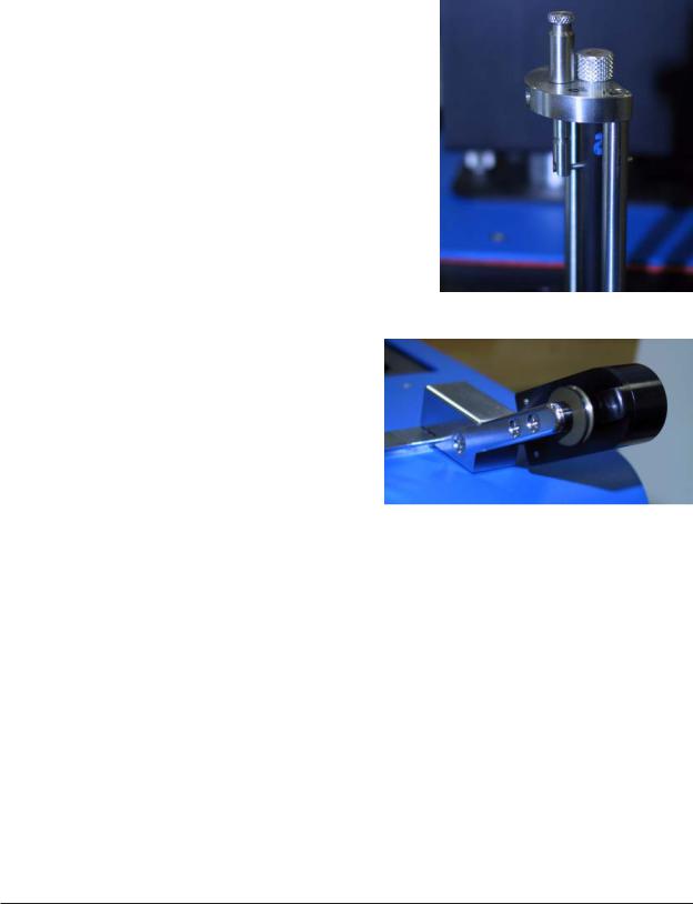
The pulley-wheel |
|
Pulley-wheel assembly |
|
|
|
assembly consists of a |
|
|
timing wheel with a |
|
|
digital-optical sensor |
|
|
permitting precise |
|
|
measurement of the |
|
|
wheel rotation. The |
|
|
pulley-wheel base is |
|
|
designed to be fitted to |
|
|
the CMRV-5000 slide |
|
|
track adjacent to the |
CMRV-5000 pulley-wheel assembly on slide |
|
viscometric cells. The |
track |
|
probe cable is con- |
|
|
nected to the jack on the front of the CMRV-5000 housing. |
|
Slide track |
The pulley-wheel assembly is designed to interlock with the pulley- |
|
|
wheel slide track and move laterally so it can be aligned with the scored |
|
|
marks on the track opposite each of the rotor shafts. |
|
Winding thread |
The thread used for CMRV-5000 testing is a single, nonelastic strand of |
|
|
70 cm (28") winding thread of silk, cotton, or similar material (Coats |
|
|
North America or comparable brand, 0.1 mm radius) with a loop on one |
|
|
end. One end is wound around the CMRV-5000 rotor. The other end of |
|
|
the thread is tied to a small rigid plastic ring from which the test weight |
|
|
may be suspended. |
|
Hook-weights |
Hook-weights are hung on the plastic ring at the free end of the thread to |
|
|
apply the required force to the rotor during yield stress and viscosity |
|
|
measurements. Nine disk weights, one hook-cage, and one larger hook- |
|
CANNON® Mini-Rotary Viscometer CMRV-5000 Instruction & Operation Manual Version 1.0b—August, 2011; CANNON® Instrument Company
2139 High Tech Road • State College, PA • 16803 • USA

9
|
weight are provided. Weights vary depending |
|
|
on the ASTM Method used for testing. |
|
Temperature probe |
CMRV-5000 block temperature is detected by |
|
|
a 3k-ohm temperature probe, which must be |
|
|
seated securely in the thermistor aperture at |
|
|
the side of the CMRV housing and plugged |
|
|
into the electronic chassis. |
|
Thermometers |
The CMRV-5000 unit is shipped from CAN- |
|
|
NON® with two thermometers to be used to |
|
|
check the temperature of the block. |
|
|
The long thermometer used for the probe |
Hook-weights |
|
and cell calibrations is a PRINCO mer- |
|
|
|
|
|
cury-thallium calibrated thermometer with |
|
|
a range of -46°C to +30°C in .2°C increments and an accuracy of ± |
|
|
0.01°C below 20°C. |
|
|
The shorter, high-temperature uncalibrated thermometer has a range |
|
|
of 0°C to 105°C in 1°C increments with an accuracy of ± 1°C. |
|
NOTE |
If a thermometer is removed from |
|
|
the CMRV-5000 when the unit is |
|
|
cooling, plug the thermometer |
|
|
aperture in the Plexiglas® cover to |
|
|
prevent ice formation around the |
|
|
rotors. |
|
Cell caps |
Cell caps are used to enhance |
|
|
temperature control and prevent |
|
|
condensation in the CMRV cells |
|
during the cooling phase of the temperature profile.
Front panel operations
Cell caps
|
CMRV front panel |
Control features |
CMRV front panel control features are simple and functional. The switch |
|
on the front panel is the power switch for the unit. The light-emitting |
CANNON® Mini-Rotary Viscometer CMRV-5000 Instruction & Operation Manual Version 1.0b—August, 2011; CANNON® Instrument Company
2139 High Tech Road • State College, PA • 16803 • USA

10
diodes (LEDs) indicate function of the heating and cooling systems. The Lemo jack connection (labeled WHEEL) on the front of the panel mates with the cable from the pulleywheel optical sensor (Do NOT plug or unplug the pulleywheel assembly when the instrument power is ON). The Start Test button is used to initiate CMRV-controlled testing and calibration routines. The Yield and Viscosity LEDs light during yield stress or viscosity testing.
For additional details on front panel operation, refer to the calibration and testing chapters of this manual.
CANNON® Mini-Rotary Viscometer CMRV-5000 Instruction & Operation Manual Version 1.0b—August, 2011; CANNON® Instrument Company
2139 High Tech Road • State College, PA • 16803 • USA

11
CHAPTER |
|
4 |
SETUP |
The instructions in this chapter are for setting up a single CMRV-5000. For additional information on multi-unit configurations, see APPENDIX D.
Physical placement
CAUTION |
The CMRV instrument is quite heavy. To avoid injury, obtain necessary |
|
assistance when lifting and moving instrument components. |
Placement |
Place the CMRV-5000 Controller/base unit on a stable laboratory bench |
|
within 10 mm of the front edge. This orientation will allow the weight |
|
suspended from the head unit pulley-wheel assembly to clear the edge of |
|
the table during viscosity and yield stress tests. Place the head unit on top |
|
of the Controller, and position the head unit so the rubber "feet" fit in the |
|
corresponding holes in the top of the Controller chassis. Allow 30.5 cm |
|
(12") of clearance to the back and sides of the units. |
Thermometer placement |
When in use, the larger thermometer (-46°C to +30°C) is placed in the |
|
thermometer well on the left side of the CMRV-5000 unit (seen from the |
|
front). |
|
When in use, the smaller thermometer (0°C to 105°C) is placed in the |
|
thermometer well on the right side of the CMRV-5000 unit (as seen from the |
|
front). |
NOTE |
If the mercury column in a thermometer has separated during shipment, |
|
read the instructions included in APPENDIX C. These instructions offer |
|
several methods for joining separated mercury columns. |
Electrical /serial connections |
|
|
Attach the DC power cable to the OUTPUT connector on the Controller |
|
and the INPUT connector on the head unit. Twist the connectors clock- |
|
wise to secure the power cable connections. |
|
Make sure the CMRV-5000 power switch on the Controller is in the OFF |
|
position; then insert the power cable into the mating receptacle on the |
|
Controller rear panel (see diagram, next page). |
Thermistor |
Insert the Lemo® plug from the temperature probe into the jack marked |
|
TEMP PROBE on rear of the CMRV Controller (see diagram, next |
|
page). Apply a generous quantity of the supplied thermal paste to the |
|
probe tip and insert the tip as far as it will go into the hole with the |
|
rubber grommet on the right side of the CMRV-5000 head unit chassis |
|
(as viewed from the front of the unit). |
CANNON® Mini-Rotary Viscometer CMRV-5000 Instruction & Operation Manual Version 1.0b—August, 2011; CANNON® Instrument Company
2139 High Tech Road • State College, PA • 16803 • USA

12
|
|
|
|
|
CMRV Head Unit rear panel |
|
|
|
|
Installing thermistor |
||||||||||||||||||||||||||||||||||||||
|
|
|
|
|
|
|
|
|
|
|||||||||||||||||||||||||||||||||||||||
|
|
|
|
|
|
|
|
|
|
|
|
|
|
|
|
|
|
|
|
|
|
|
|
|
|
|
|
|
|
|
|
|
|
|
|
|
|
|
|
|
|
|
|
|
|
|
|
|
|
|
|
|
|
|
|
|
|
|
|
|
|
|
|
|
|
|
|
|
|
|
|
|
|
|
|
|
|
|
|
|
|
|
|
|
|
|
|
|
|
|
|
|
|
|
|
|
|
|
|
|
|
|
|
|
|
|
|
|
|
|
|
|
|
|
|
|
|
|
|
|
|
|
|
|
|
|
|
|
|
|
|
|
|
|
|
|
|
|
|
|
|
|
|
|
|
|
|
|
|
|
|
|
|
|
|
|
|
|
|
|
|
|
|
|
|
|
|
|
|
|
|
|
|
|
|
|
|
|
|
|
|
|
|
|
|
|
|
|
|
|
|
|
|
|
|
|
|
|
|
|
|
|
|
|
|
|
|
|
|
|
|
|
|
|
|
|
|
|
|
|
|
|
|
|
|
|
|
|
|
|
|
|
|
|
|
|
|
|
|
|
|
|
|
|
|
|
|
|
|
|
|
|
|
|
|
|
|
|
|
|
|
|
|
|
|
|
|
|
|
|
|
|
|
|
|
|
|
|
|
|
|
|
|
|
|
|
|
|
|
|
|
|
|
|
|
|
|
|
|
|
|
|
|
|
|
|
|
|
|
|
|
|
|
|
|
|
|
|
|
|
|
|
|
|
|
|
|
|
|
|
|
|
|
|
|
|
|
|
|
|
|
|
|
|
|
|
|
|
|
|
|
|
|
|
|
|
|
|
|
|
|
|
|
|
|
|
|
|
|
|
|
|
|
|
|
|
|
|
|
|
|
|
|
|
|
|
|
|
|
|
|
|
|
|
|
|
|
|
|
|
|
|
|
|
|
|
|
|
|
|
|
|
|
|
|
|
|
|
|
|
|
|
|
|
|
|
|
|
|
|
|
|
|
|
|
|
|
|
|
|
|
|
|
|
|
|
|
|
|
|
|
|
|
|
|
|
|
|
|
|
|
|
|
|
|
|
|
|
|
|
|
|
|
|
|
|
|
|
|
|
|
|
|
|
|
|
|
|
|
|
|
|
|
|
|
|
|
|
|
|
|
|
|
|
|
|
|
|
|
|
|
|
|
|
|
|
|
|
|
|
|
|
|
|
|
|
|
|
|
|
|
|
|
|
|
|
|
|
|
|
|
|
|
|
|
|
|
|
|
|
|
|
|
|
|
|
|
|
|
|
|
|
|
|
|
|
|
|
|
|
|
|
|
|
|
|
|
|
|
|
|
|
|
|
|
|
|
|
|
|
|
|
|
|
|
|
|
|
|
|
|
|
|
|
|
|
|
|
|
|
|
|
|
|
|
|
|
|
|
|
|
|
|
|
|
|
|
|
|
|
|
|
|
|
|
|
|
|
|
|
|
|
|
|
|
|
|
|
|
|
|
|
|
|
|
|
|
|
|
|
|
|
|
|
|
|
|
|
|
|
|
|
|
|
|
|
|
|
|
|
|
|
|
|
|
|
|
|
|
|
|
|
|
|
|
|
|
|
|
|
|
|
|
|
|
|
|
|
|
|
|
|
|
|
|
|
|
|
|
|
|
|
|
|
|
|
|
|
|
|
|
|
|
|
|
|
|
|
|
|
|
|
|
|
|
|
|
|
|
|
|
|
|
|
|
|
|
|
|
|
|
|
|
|
|
|
|
|
|
|
|
|
|
|
|
|
|
|
|
|
|
|
|
|
|
|
|
|
|
|
|
|
|
|
|
|
|
|
|
|
|
|
|
|
|
|
|
|
|
|
|
|
|
|
|
|
|
|
|
|
|
|
|
|
|
|
|
|
|
|
|
|
|
|
|
|
|
|
|
|
|
|
|
|
|
|
|
|
|
|
|
|
|
|
|
|
|
|
|
|
|
|
|
|
|
|
|
|
|
|
|
|
|
|
|
|
|
|
|
|
|
|
|
|
|
|
|
|
|
|
|
|
|
|
|
|
|
|
|
|
|
|
|
|
|
|
|
|
|
|
|
|
|
|
|
|
|
|
|
|
|
|
|
|
|
|
|
|
|
|
|
|
|
|
|
|
|
|
|
|
|
|
|
|
|
|
|
|
|
|
|
|
|
|
|
|
|
|
|
|
|
|
|
|
|
|
|
|
|
|
|
|
|
|
|
|
|
|
|
|
|
|
|
|
|
|
|
|
|
|
|
|
|
|
|
|
|
|
|
|
|
|
|
|
|
|
|
|
|
|
|
|
|
|
|
|
|
|
|
|
|
|
|
|
|
|
|
|
|
|
|
|
|
|
|
|
|
|
|
|
|
|
|
|
|
|
|
|
|
|
|
|
|
|
|
|
|
|
|
|
|
|
|
|
|
|
|
|
|
|
|
|
|
|
|
|
|
CMRV Controller rear panel
CMRV-5000 power cord Make sure the CMRV-5000 power switch is in the OFF position. Then insert the power line cord from the rear panel of the CMRV Controller into an appropriate power source for your unit
CAUTION |
Before providing mains power to the unit, check the label on the rear |
|
panel of the Controller/Controller to verify that the electrical specifications |
|
for the unit match the mains. Use only the supplied, approved appliance |
|
cords for the CMRV. |
CANNON® Mini-Rotary Viscometer CMRV-5000 Instruction & Operation Manual Version 1.0b—August, 2011; CANNON® Instrument Company
2139 High Tech Road • State College, PA • 16803 • USA

13
Serial connections |
To connect a single CMRV-5000 instrument to the host computer, |
|
connect the computer cable to the RS-232, DB-9-pin socket at the rear of |
|
the CMRV-5000 Controller and secure the cable connection with the two |
|
small screws on the ears of the plug. Attach the other end of the cable to |
|
the RS-232 port at the rear of your computer. |
NOTES |
COM 2 and COM 4 use the same IRQ settings on most computers, |
|
meaning that they cannot be used simultaneously. The COM 1 and COM |
|
3 ports have the same problem. Do not try to use a device on COM 4 if |
|
you are using COM 2 for the CMRV instrument. |
|
Some display adaptors (in particular, S3, 8514A and ATI mach 8) have an |
|
address conflict with COM 4 ports. If this is the case, you may need to |
|
use another COM port or replace your current display adaptor. |
RS-485 serial connections To install multiple CMRV units using RS-485 serial cable connections, see the multi-unit configuration instructions in APPENDIX D.
Pulley-wheel installation
To install the pulley-wheel assembly atop the CMRV5000, slide it onto the stainless steel slide track atop the head unit with the pulley-wheel facing out (see photo). The bevelled fitting on the base of the pulley-wheel assembly will mate with the slide-track to secure the assembly to the head unit. The pulleywheel should be positioned on the track opposite the viscometer during testing. The scored lines on the track will assist with orientation.
CAUTION |
Use care in handling the |
|
pulley-wheel assembly to |
|
avoid damage to the wheel |
|
or the movement sensor. |
|
Make sure that the assem- |
|
bly is seated securely on |
|
the track prior to testing. |
|
With the power off, plug |
|
the free end of the pulley- |
|
wheel sensor wire into the |
|
jack labelled WHEEL on the front of the CMRV-5000 Controller. |
CANNON® Mini-Rotary Viscometer CMRV-5000 Instruction & Operation Manual Version 1.0b—August, 2011; CANNON® Instrument Company
2139 High Tech Road • State College, PA • 16803 • USA

14
CAUTION |
Do NOT plug or unplug the pulleywheel assembly when the instrument |
|
power is ON! To disconnect the sensor, pull it out by the knurled portion of |
|
the plug. |
Firmware installation notes |
|
Download button |
Current firmware is installed on your instrument during factory check- |
|
out. However, the CMRV-5000 is capable of receiving firmware updates |
|
from the computer. |
|
When installing firmware, place the instrument in the firmware down- |
|
load mode by pressing the DOWNLOAD button adjacent to the serial |
|
port on the rear of the Controller. Follow the software prompts of the |
|
firmware installation program to upgrade your instrument. |
NOTE |
If the DOWNLOAD button is pressed inadvertently, switch off the CMRV- |
|
5000 power for at least four seconds, then |
|
restore power to the unit. |
Setting the CMRV instrument address
|
When installing/connecting a new CMRV |
|
|
instrument, you must set the instrument |
Address selection knob |
|
address using the SELECT ADDRESS |
|
|
|
|
|
dial on the rear of the CMRV Controller. |
|
|
This dial offers 16 settings (0-9, A-F). |
|
Procedure |
To set the address, rotate the dial (see photo) to a setting not currently in |
|
|
use by other CMRV instruments. |
|
 CAUTION The MRVW software will not function correctly unless each networked CMRV instrument is set to a different address (see APPENDIX D for multi-unit configuration).
Gas Purge option installation
If you have purchased the Gas Purge option for your CMRV instrument, locate the Gas Purge kit, including the gas purge regulator, connecting hardware, installation mounting bracket, and quick-connect gas purge line. Obtain a Phillips screwdriver and follow the installation instructions below:
1.Remove the two "plug" screws on the center of the left side panel of the head unit (as viewed from the front of the unit). The screws are located between the grillwork and are aligned vertically approximately 82.5 mm (3.25") apart.
2.Align the mounting bracket of the gas purge assembly with the screw holes so that the connecting hardware on the attached regulator faces the rear of the head unit. Secure with the Phillips-head screws provided.
CANNON® Mini-Rotary Viscometer CMRV-5000 Instruction & Operation Manual Version 1.0b—August, 2011; CANNON® Instrument Company
2139 High Tech Road • State College, PA • 16803 • USA
15
3.Attach the quick connect tubing from the matching connector on the regulator to the PURGE IN connector on the head unit rear panel. Secure both connections by turning the tube fitting clockwise until the connection snaps securely into place.
If necessary, turning the tube fitting counterclockwise will release the connection.
4.Attach the regulated pressure line from your nitrogen source (3 psig maximum recommended) to the fitting opposite the flow adjust control on the gas purge regulator.
5.Engage the regulated flow of gas and turn the flow adjust dial until the float is in the middle of the scale. When the flow has been adjusted, turn off the flow at the nitrogen source. You may restore it prior to running the temperature profile for your samples.
For additional information consult the flow meter instructions and calibration certficate shipped with your flow meter.


 WARNING Never exceed the maximum pressure of 200 PSIG for gas pressure to the regulator, as it will create a hazard.
Maintaining the air filters
The CMRV-5000 has been designed with easily-replaceable air filters for the cooling fans on the front and rear of the Control Unit housing. The filters help ensure adequate function of the fans, which help remove heat from the hot side of the thermoelectric cooling units. The filters should be replaced every three months if the instrument is used constantly, or every six months if the instrument is used frequently.
To replace filters, slide the filters out of the mounting slots on the front and rear of the Control Unit. Then slide in the replacement filters.
Cleaning the instrument housing
Periodically clean the outside of the unit with a damp cloth moistened with water and/or a mild detergent solution.
CAUTION Because of temperature extremes of viscosity testing, use caution handling the CMRV viscometer cells before or after a test. Do not clean the instrument unless the cell temperature is within 10°C of ambient. Before cleaning the CMRV housing, turn off the instrument and unplug the power cord.
CANNON® Mini-Rotary Viscometer CMRV-5000 Instruction & Operation Manual Version 1.0b—August, 2011; CANNON® Instrument Company
2139 High Tech Road • State College, PA • 16803 • USA

16
This page intentionally left blank.
CANNON® Mini-Rotary Viscometer CMRV-5000 Instruction & Operation Manual Version 1.0b—August, 2011; CANNON® Instrument Company
2139 High Tech Road • State College, PA • 16803 • USA

17
CHAPTER |
|
5 |
VISCPRO® INSTALLATION |
VISCPRO ® for Windows® XP®
VISCPRO® is a powerful software product providing a generic instrument interface for controlling and operating multiple CANNON® instrument(s) via computer. VISCPRO® also includes reporting/analysis modules for processing and displaying sample data.
Installing VISCPRO ® software
To install the VISCPRO® software, follow the instructions below in the sequence presented. Make certain that you complete the sections on checking instrument settings and calibration data. If you encounter difficulties at any stage in the installation process, call CANNON® service at 814-353-8000.
Computer requirements
See specifications sheet provided with your instrument.
Windows® XP® installation
1.Turn on your computer. Wait for the Windows® software to load.
2.From the Windows® Start Bar click Settings/Control Panel. Insert the VISCPRO® installation CD-ROM into the disk drive.
3.If the installation program does not begin automatically, select your computer's Add/Remove Programs option from the Windows® Control Panel. Then follow the Windows prompts to complete the installation procedure. The executable file for VISCPRO® software installation is SETUP.EXE.
Installation actions
The installation program will:
create a directory for your data files and database. The location(s) may depend on your operating system (see Application Note provided with your instrument).
write SETUP information to the Windows® registry.
copy the software executable file and other necessary files to the directory you specify.
update other files in your Windows® directories to versions fully compatible with the current VISCPRO® software.
place a shortcut icon for the VISCPRO® executable file on your Windows® desktop.
CANNON® Mini-Rotary Viscometer CMRV-5000 Instruction & Operation Manual Version 1.0b—August, 2011; CANNON® Instrument Company
2139 High Tech Road • State College, PA • 16803 • USA

18
Running the software
Loading software
Make certain that your CMRV instrument is properly connected to your computer and the CMRV power switch is ON. Then start the VISCPRO® software by double-clicking the VISCPRO® icon on your Windows® desktop. Or click Start/Programs/VISCPRO/VISCPRO.EXE).
Right now, your computer monitor should look like this:
The VISCPRO® primary display
The VISCPRO® primary display window is framed on the top by the VISCPRO® title bar and menu bar, and on the bottom by the VISCPRO® status bar.
Displaying the Instrument View window
The application window can be configured to display child windows, such as the Instrument View window, which describes your CANNON® instrument and provides controls for running tests:
CANNON® Mini-Rotary Viscometer CMRV-5000 Instruction & Operation Manual Version 1.0b—August, 2011; CANNON® Instrument Company
2139 High Tech Road • State College, PA • 16803 • USA

19
The Instrument View window
NOTE |
To display the Instrument View window, click View Instrument from the |
|
Main menu. The View Instrument window will appear. Then click the |
|
MRV instrument ID to display the list of available configurations. For now, |
|
select the default configuration and click OK. |
Instrument ID/Type
Instrument Configuration
If the Available Instruments list box is blank, your instrument(s) may not be on-line. Check cable connections and make certain the instrument power switch is ON.
CANNON® Mini-Rotary Viscometer CMRV-5000 Instruction & Operation Manual Version 1.0b—August, 2011; CANNON® Instrument Company
2139 High Tech Road • State College, PA • 16803 • USA

20
Viewing report data
After you have completed CMRV calibration and testing (see next chapters), you will be able to display a report window with CMRV-5000 test results. To access the database and display test data, click Analyses/ View Analysis. Then select MRV Data Table from the list of available analyses:
Report Type
Report Configuration
The Choose Analysis window
Choose the desired report configuration from the list of available configurations and then click OK to open the Analysis Configuration window. Then select report configuration options (see Chapter 13 for more information) and click OK to generate the analysis from existing sample data. If the report window is blank, you may have to change the Date Filter options to include the desired range of samples from the database.
The Sample Analysis Table window
CANNON® Mini-Rotary Viscometer CMRV-5000 Instruction & Operation Manual Version 1.0b—August, 2011; CANNON® Instrument Company
2139 High Tech Road • State College, PA • 16803 • USA

21
Checking Configuration data |
Follow the procedures in the next several sections of this chapter to |
|
select and verify the instrument and calibration settings to ensure that |
|
they conform to the actual characteristics of your CANNON® instru- |
|
ment. |
Verifying configuration |
To check the configuration settings for your instrument(s), you must log |
|
in to the security system as a manager. The software is installed with a |
|
default Manager account. This account has no password, allowing any |
|
operator access to manager-level software functions as long as the |
|
password is not activated/changed. If you would like to engage the full- |
|
release security options, see Security Options, this chapter, for instruc- |
|
tions. |
Logging in
1.Use your mouse to click Main from the VISCPRO® menu bar.
2.Click Log In from the Main menu options.
3.Click on the  (arrow) on the right side of the User Name: list box to display the list of registered users.
4.Click Manager. Do NOT enter a password!
5.Click OK. The Log In window will close automatically and you will be logged in as management personnel.
Checking Instrument Settings
1.Use your mouse to click (select) Configure from the VISCPRO® menu bar.
2.Select your instrument from the list of available instruments (there may be only one instrument in the list).
3.Select Instrument Settings from the list of configuration options. The Instrument Settings window will appear.
Instrument settings |
You will use the Instrument Settings window (see graphic following) to |
|
describe and control CMRV instrument operational features. These |
|
settings affect the instrument as a whole. Check the instrument settings |
|
for your instrument per the instructions, and make any necessary |
|
changes: |
CANNON® Mini-Rotary Viscometer CMRV-5000 Instruction & Operation Manual Version 1.0b—August, 2011; CANNON® Instrument Company
2139 High Tech Road • State College, PA • 16803 • USA

22
The Instrument Settings window
Checking initial calibration
NOTE
4.Use the ID field to input instrument identification information using up to 30 alphanumeric characters.
The remaining fields in the Instrument Settings window are noneditable (information is obtained via serial communication with the CMRV instrument). The Model: field will indicate the model of your instrument. The S/N: field indicates the serial number from the label on the Controller rear panel. The Firmware: field indicates the version for the current instrument firmware. The Port: field indicates the current communications port for the RS-232 cable connecting your computer to the CMRV-5000 instrument.
5.When you have entered all settings, click OK.
After you have completed the CMRV instrument calibration for temperature and cell constants (see following chapters), follow the procedure below to verify the initial calibration settings.
1.From the VISCPRO primary window, click Configure/MRV/View Cell Constants. The View Cell Constants window will open.
2.Ensure that Calibration data, including constants and viscosity, is available for each cell. Then click OK to close the View Cell Constants window.
Some fields/options are security-protected, and may not be viewable.
CANNON® Mini-Rotary Viscometer CMRV-5000 Instruction & Operation Manual Version 1.0b—August, 2011; CANNON® Instrument Company
2139 High Tech Road • State College, PA • 16803 • USA

23
The View Cell Constants window
3.Click Configuration/Print Instrument Settings to open the Windows® Print window. Select the desired printer and click OK to print current calibration settings.
NOTE |
CANNON recommends printing calibration settings each time the calibra- |
|
tion values change. |
Setting multiple CMRV instrument addresses
When installing/connecting multiple CMRV instruments, ensure that the instrument address for each instrument is different. See APPENDIX D for more information on multi-unit configuration.
Security options
The VISCPRO® application offers a level-based security system with a log in procedure. This system ensures that available software functions are appropriate for the user's needs.
Following initial installation of the software, security options may be accessed and changed from the VISCPRO® Main menu by individuals who have the manager password (initially blank).
Each user can be assigned a security level, which is used to determine permitted operations. Three security levels are defined by the software: Technician (least privileged), Manager (intermediate privilege), and Service (maximum privilege–reserved for CANNON® Instrument Company service personnel).
Users log in when using the software by typing their name and (optional) password in the Log In window. Different security levels offer different instrument use options. Technicians are permitted to access operational features required for testing samples and performing other routine operations. Managers may configure technician accounts/passwords and access protected advanced configuration and reporting options. The Service level permits access to all instrument and security parameters.
CANNON® Mini-Rotary Viscometer CMRV-5000 Instruction & Operation Manual Version 1.0b—August, 2011; CANNON® Instrument Company
2139 High Tech Road • State College, PA • 16803 • USA

24
Initial security setup
The VISCPRO® software installation creates a security account for one manager with a blank password. After VISCPRO® installation, a password should be assigned for the manager using the Change Password menu option from Main. Managers may add or change accounts for technician status personnel.
Use the Log In feature to identify the CMRV operator and/or access security functions.
NOTE |
Once an operator is logged in, that operator’s name is associated with |
|
|
any sample data obtained during that VISCPRO session. The operator |
|
|
name may be included in analyses. |
|
Procedure |
1. |
Click Log In from Main. |
|
2. |
Select the desired name from the drop-down list box. |
|
3. |
Type the desired password in the Password field for the individual |
|
|
selected. |
|
4. |
Click OK. |
|
Use the Change Password feature to change the current user password. |
|
Procedure |
1. |
Log in to the VISCPRO® software using the Log In command from |
|
|
Main. |
|
2. |
Select Change Password from the Main menu options. |
|
3. |
Type in the new password in the Password field. |
|
4. |
Retype the password in the Confirm Your New Password field. |
|
5. |
Click OK to save the new password and close the Change Pass- |
|
|
word window. |
|
Use the Update User Information feature to update the security list of |
|
|
authorized technicians and managers. User information can only be |
|
|
updated by an individual logged in with a higher security clearance than |
|
|
the user for which information is to be altered. Manager status is |
|
|
necessary to change Technician information. Service status is neces- |
|
|
sary to change Manager information. To obtain Service status, it is |
|
|
necessary to select user CANNON Instrument Company from the Log |
|
|
In window and to type in the current CANNON® password. For the |
|
|
current password (updated daily), call CANNON® at (814) 353-8000. |
|
Procedure |
1. |
Click Log In from Main. |
|
2. |
Select your Manager or Service level user name from the User |
|
|
Name list box. Input the correct password in the appropriate field. |
|
3. |
Click OK. |
CANNON® Mini-Rotary Viscometer CMRV-5000 Instruction & Operation Manual Version 1.0b—August, 2011; CANNON® Instrument Company
2139 High Tech Road • State College, PA • 16803 • USA
 Loading...