


i
CONTENTS
1 |
INTRODUCTION/SOFTWARE INSTALLATION |
1 |
|
The CANNON® Automatic Viscometer (CAV 2000 Series) .............................................. |
1 |
|
Measuring kinematic viscosity ........................................................................................... |
2 |
|
Safety cautions.................................................................................................................... |
2 |
|
Specifications ..................................................................................................................... |
4 |
|
VISCPRO® for Windows® .................................................................................................. |
5 |
|
Installing VISCPRO® software ........................................................................................... |
5 |
|
Computer requirements .......................................................................................... |
5 |
|
Windows® XP® installation.................................................................................... |
5 |
|
Installation actions .................................................................................................. |
5 |
|
Configuration diskette (First-time installation only!) ............................................ |
5 |
|
Running the software .......................................................................................................... |
6 |
|
Checking configuration ...................................................................................................... |
8 |
|
Configuration disk .................................................................................................. |
8 |
|
Logging in .............................................................................................................. |
8 |
|
Checking Instrument Settings................................................................................. |
9 |
|
Viewing/editing setup information ....................................................................... |
10 |
|
Manually changing tube calibration constants ................................................................. |
11 |
2 |
TESTING SAMPLES |
|
|
WITH THE CANNON AUTOMATIC VISCOMETER |
15 |
|
Preparing the CAV ............................................................................................................ |
15 |
|
Preparing sample trays ......................................................................................... |
15 |
|
Inserting/removing the CAV reference thermometer ........................................... |
16 |
|
Local mode operation ....................................................................................................... |
17 |
|
Setting temperature ............................................................................................... |
17 |
|
Preparing the bath ................................................................................................. |
18 |
|
Testing samples..................................................................................................... |
18 |
|
Aborting a test ...................................................................................................... |
18 |
|
Concluding a test .................................................................................................. |
19 |
|
Obtaining kinematic viscosity (KV) readings in Local mode .............................. |
19 |
|
Other Local mode keypad options ........................................................................ |
19 |
|
Remote operation (computer-controlled) ......................................................................... |
20 |
|
Setting temperature ............................................................................................... |
20 |
|
Testing samples..................................................................................................... |
22 |
|
Pausing a test ........................................................................................................ |
24 |
|
Resuming a test..................................................................................................... |
25 |
|
Aborting a test ...................................................................................................... |
25 |
CANNON® Automatic Viscometer Models CAV-2100 and CAV-2200 with VISCPRO® Instruction & Operation Manual Version 2g — May 2009; CANNON® Instrument Company
2139 High Tech Road • State College, PA 16803 • USA

ii
|
Concluding a test .................................................................................................. |
|
|
25 |
|
Working with Instrument Groups ..................................................................................... |
|
|
25 |
|
Group configuration ............................................................................................. |
|
|
27 |
|
Configuring the Machine Status window to correspond with physical instrument |
|||
|
placement .............................................................................................................. |
|
|
27 |
|
Viewing test results........................................................................................................... |
|
|
27 |
|
Creating an analysis .......................................................................................................... |
|
|
28 |
3 |
CALIBRATING THE CAV |
29 |
|
|
|
Calibrating temperature .................................................................................................... |
|
|
29 |
|
Calibration procedure ........................................................................................... |
|
|
29 |
|
Training sensors ................................................................................................................ |
|
|
30 |
|
Standard tube calibration .................................................................................................. |
|
|
30 |
|
Calibration procedure ........................................................................................... |
|
|
31 |
|
Saving a calibration .............................................................................................. |
|
|
33 |
|
CAV calibration equations .................................................................................... |
|
|
34 |
4 |
USING THE CAV SOFTWARE |
35 |
|
|
|
VISCPRO® generic instrument interface ........................................................................ |
|
|
35 |
|
Main options ......................................................................................................... |
|
|
36 |
|
Security options .................................................................................................... |
|
|
37 |
|
Initial security setup ............................................................................................. |
|
|
37 |
|
Adjusting Security Settings .................................................................................. |
|
|
39 |
|
Print/Print setup options ....................................................................................... |
|
|
39 |
|
Analyses options ............................................................................................................... |
|
|
40 |
|
Analysis types ....................................................................................................... |
|
|
40 |
|
Analyses menu options ......................................................................................... |
|
|
40 |
|
Window options ................................................................................................................ |
|
|
42 |
|
CAV module menu options ............................................................................................... |
|
|
43 |
|
Configure options ................................................................................................. |
|
|
43 |
|
Print Instrument and Tray Settings ....................................................................... |
|
|
43 |
|
Instrument Settings ............................................................................................... |
|
|
45 |
|
Tray Settings: Tube and Bath ............................................................................... |
|
|
46 |
|
Tray Settings: Test ................................................................................................ |
|
|
48 |
|
Tray Settings: Wash .............................................................................................. |
|
|
50 |
|
Tray Settings: Advanced ....................................................................................... |
|
|
52 |
|
Saving a configuration .......................................................................................... |
|
|
54 |
|
Restoring instrument settings from a saved configuration ................................... |
54 |
||
|
Calibration ............................................................................................................ |
|
|
55 |
|
Service menu options ....................................................................................................... |
|
|
57 |
|
Testing samples—software options .................................................................................. |
|
|
58 |
|
Entering sample ID information ........................................................................... |
|
|
58 |
CANNON® Automatic Viscometer Models CAV-2100 and CAV-2200 with VISCPRO® Instruction & Operation Manual Version 2g — May, 2009; CANNON® Instrument Company
2139 High Tech Road • State College, PA 16803 • USA

iii
|
Selecting sample actions....................................................................................... |
59 |
|
Viscosity Action for viscosity standards .............................................................. |
61 |
|
Copy & Paste Sample ID data entry options ........................................................ |
61 |
|
Inserting/deleting a sample ID in the test sequence ............................................. |
62 |
|
CAV analysis modules .......................................................................................... |
62 |
|
Configuring the VI Matcher ............................................................................................. |
62 |
|
Turning off the VI Matcher .................................................................................. |
64 |
|
Handling errors ................................................................................................................. |
64 |
|
Configuring the Energy Saver .......................................................................................... |
65 |
5 |
OPERATING, MAINTAINING AND SERVICING THE CAV |
69 |
|
CAV components .............................................................................................................. |
69 |
|
Bath Unit .............................................................................................................. |
69 |
|
SDU-200 Solvent Dispensing System .................................................................. |
70 |
|
CSU-200 Service Unit .......................................................................................... |
70 |
|
Emptying the waste can .................................................................................................... |
70 |
|
Viscometer tubes .............................................................................................................. |
71 |
|
Tube thermistors ................................................................................................... |
71 |
|
Fast-run viscometer tubes ..................................................................................... |
72 |
|
Temperature bath .............................................................................................................. |
72 |
|
Expansion vessel (CAV-2100 only) ...................................................................... |
72 |
|
Filling the bath ...................................................................................................... |
73 |
|
Draining the bath .................................................................................................. |
74 |
|
Bath heaters .......................................................................................................... |
74 |
|
Heat shield (optional) ........................................................................................... |
74 |
|
Bath fluid safety features ...................................................................................... |
75 |
|
Temperature probes .............................................................................................. |
75 |
|
Sample trays/drains .......................................................................................................... |
75 |
|
Splash guards ........................................................................................................ |
76 |
|
Solvent system .................................................................................................................. |
76 |
|
Solvent Dispensing Unit ....................................................................................... |
77 |
|
Checking solvent levels ........................................................................................ |
77 |
|
Solvent/drain lines ................................................................................................ |
77 |
|
Waste can .............................................................................................................. |
78 |
|
Drip pan ................................................................................................................ |
78 |
|
Ventilation......................................................................................................................... |
78 |
|
Checking bath temperature ............................................................................................... |
79 |
|
Setting bath temperature ................................................................................................... |
79 |
|
Service Unit operational settings ...................................................................................... |
79 |
|
Regulating pneumatic pressure............................................................................. |
80 |
|
Regulating solvent flow ........................................................................................ |
80 |
|
Regulating vacuum ............................................................................................... |
80 |
|
Adjusting pneumatic controls ........................................................................................... |
80 |
|
Dual-solvent washing ....................................................................................................... |
81 |
CANNON® Automatic Viscometer Models CAV-2100 and CAV-2200 with VISCPRO® Instruction & Operation Manual Version 2g — May 2009; CANNON® Instrument Company
2139 High Tech Road • State College, PA 16803 • USA

iv
|
Solvent wash by computer (Remote mode) ...................................................................... |
|
|
81 |
||||
|
Solvent wash by operator (Local mode) ........................................................................... |
|
|
82 |
||||
|
Setting wash parameters (Local mode) ................................................................ |
82 |
||||||
|
Wash configuration options (Remote mode) .................................................................... |
|
|
83 |
||||
|
Manually cleaning contaminated viscometer tubes.......................................................... |
83 |
||||||
|
Handling fault conditions ................................................................................................. |
|
|
84 |
||||
|
Preventive maintenance .................................................................................................... |
|
|
85 |
||||
|
Changing the vacuum pump diaphragm ............................................................... |
86 |
||||||
|
CAV repair/replacement kits ............................................................................................ |
|
|
87 |
||||
6 |
ANALYSIS CONFIGURATION OPTIONS |
89 |
|
|
||||
|
Creating an analysis .......................................................................................................... |
|
|
89 |
||||
|
Sorting analysis data ......................................................................................................... |
|
|
90 |
||||
|
Using the date filter .......................................................................................................... |
|
|
90 |
||||
|
Using the sample filter...................................................................................................... |
|
|
91 |
||||
|
Using the report/port output filter..................................................................................... |
|
|
93 |
||||
|
Reconfiguring a displayed analysis .................................................................................. |
|
|
93 |
||||
|
Resizing table columns ..................................................................................................... |
|
|
93 |
||||
|
Saving a current analysis .................................................................................................. |
|
|
93 |
||||
|
Deleting an analysis configuration ................................................................................... |
|
|
94 |
||||
|
Printing an analysis........................................................................................................... |
|
|
94 |
||||
|
Keystrokes for selecting data for printing ............................................................ |
94 |
||||||
|
Exporting analysis data..................................................................................................... |
|
|
95 |
||||
7 |
CAV DATA TABLE |
97 |
|
|
|
|
|
|
|
Configuring the CAV Data Table.......................................................................... |
|
|
98 |
||||
8 |
STANDARD VI TABLE ANALYSIS |
|
|
103 |
|
|
||
|
Configuring the standard VI table ...................................................................... |
|
|
|
103 |
|||
9 |
SAMPLE DATA EXPORT ANALYSIS |
107 |
||||||
|
Configuring the Sample Data Export analysis ................................................... |
|
108 |
|||||
10 |
VI DATA EXPORT ANALYSIS |
|
|
113 |
|
|
|
|
|
Configuring the VI Data Export Analysis .......................................................... |
|
114 |
|||||
11 |
ERROR DATA EXPORT ANALYSIS |
|
|
119 |
|
|
|
|
CANNON® Automatic Viscometer Models CAV-2100 and CAV-2200 with VISCPRO® Instruction & Operation Manual Version 2g — May, 2009; CANNON® Instrument Company
2139 High Tech Road • State College, PA 16803 • USA

v
|
Configuring the Error Data Export analysis |
....................................................... |
|
|
119 |
||
12 |
ERROR LOG TABLE ANALYSIS |
125 |
|
||||
|
Configuring the Error Log analysis .................................................................... |
|
|
|
125 |
||
13 |
USING THE DATABASE MANAGER |
129 |
|
||||
|
Archiving old data .............................................................................................. |
|
|
|
|
|
130 |
|
Changing the database directory ........................................................................ |
|
|
|
130 |
||
|
Importing archived data ...................................................................................... |
|
|
|
|
|
131 |
|
Repairing/compacting the database .................................................................... |
|
|
|
131 |
||
|
Exit ..................................................................................................................... |
|
|
|
|
|
131 |
14 |
REPLACEMENT PARTS LIST |
|
|
133 |
|
|
|
|
CAV-2100 ....................................................................................................................... |
|
|
|
|
|
133 |
|
CAV-2200 ....................................................................................................................... |
|
|
|
|
|
134 |
A |
APPENDIX A–REPLACING THE CAV-2200 THERMOMETER |
135 |
|||||
|
Tools required ................................................................................................................. |
|
|
|
|
|
135 |
|
Procedural overview ....................................................................................................... |
|
|
|
|
|
135 |
|
Disassembly/removal procedure .................................................................................... |
|
|
|
|
|
135 |
|
Assembly procedure ....................................................................................................... |
|
|
|
|
|
136 |
I |
INDEX |
137 |
|
|
|
|
|
CANNON® Automatic Viscometer Models CAV-2100 and CAV-2200 with VISCPRO® Instruction & Operation Manual Version 2g — May 2009; CANNON® Instrument Company
2139 High Tech Road • State College, PA 16803 • USA

vi
This page intentionally left blank.
CANNON® Automatic Viscometer Models CAV-2100 and CAV-2200 with VISCPRO® Instruction & Operation Manual Version 2g — May, 2009; CANNON® Instrument Company
2139 High Tech Road • State College, PA 16803 • USA
1
CHAPTER
1 INTRODUCTION/SOFTWARE INSTALLATION
The CANNON® Automatic Viscometer (CAV 2000 Series)
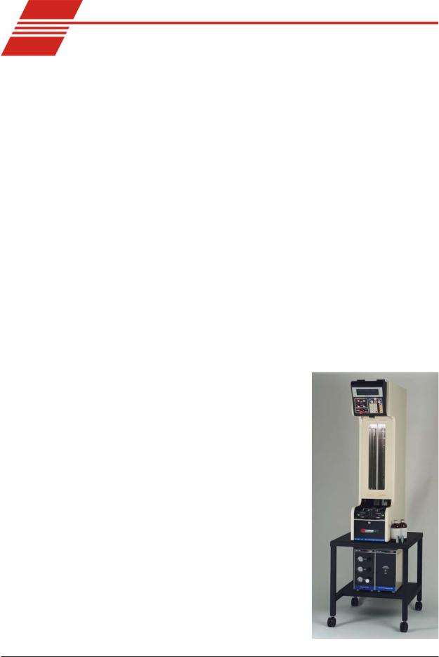
The CANNON® Automatic Viscometer (CAV) is a completely automatic viscometer designed for unattended operation. The operator places samples in small vials in the sample holders, enters sample identification information and initiates the testing with software or front panel keypad commands. Without any further operator involvement, the CAV determines kinematic viscosity, cleans the capillary tube(s) and prepares the instrument for the next test. All pertinent test data can be saved to a computer database for future retrieval and reporting.
Manual |
This manual is designed to provide the operator with information about: |
VISCPRO® software installation and operation
|
CAV 2000 Series equipment and operation |
|
|
Calibration, service and maintenance procedures |
|
|
For additional information on initial installation and instrument setup, |
|
|
refer to the Installation & Setup Guide. |
|
Applications |
Previous CAV models have been used |
|
|
in laboratories worldwide for over two |
|
|
decades. CAV instruments can be found |
|
|
in R&D laboratories, refinery quality |
|
|
control laboratories, blending plants, |
|
|
and independent testing laboratories. |
|
|
The CAV is ideally suited for the |
|
|
analysis of both transparent and opaque |
|
|
samples. A variety of materials, such as |
|
|
used oils, marine fuels, residual fuels, |
|
|
and crude oils can be tested with ease. |
|
Precision |
Precision for the kinematic viscosity |
|
|
determination of the CAV equals or |
|
|
exceeds that specified in ASTM |
|
|
Method D 445. This method is required |
|
|
by the Society of Automotive Engineers |
|
|
(SAE) Engine Oil Viscosity Classifica- |
|
|
tion SAE J300. |
The CAV-2200 |
CANNON® Automatic Viscometer Models CAV-2100 and CAV-2200 with VISCPRO® Instruction & Operation Manual Version 2g — May, 2009; CANNON® Instrument Company
2139 High Tech Road • State College, PA 16803 • USA

2
Measuring kinematic viscosity
|
Kinematic viscosity is a measure of the internal resistance to flow of a |
|
fluid under gravity with the pressure head being proportional to the |
|
density of the fluid. For any particular viscometer, the time of flow of a |
|
fixed volume of fluid is directly proportional to its kinematic viscosity. |
Units of measure |
An accepted unit of kinematic viscosity is one centimeter squared per |
|
second, which is called one stoke. The centistoke (which is equivalent to |
|
1 mm2/s) is the unit of measure most frequently used. |
Methodology |
ASTM Methods D 445 and D 446, included with this manual, describe |
|
appropriate test methodologies and instruments for glass capillary |
|
viscometry. |
Manual viscometers |
Sections 9-11 of ASTM D 445 provide detailed instructions for using |
|
manual viscometers. ASTM D 446 suggests a minimum flow time of 200 |
|
seconds for nearly all the glass capillary viscometers (see tables in ASTM |
|
D 446). |
Automatic viscometers |
For automatic viscometers, ASTM D 445 Section 6.1.2 states, “Auto- |
|
mated apparatus may be used as long as they mimic the physical condi- |
|
tions, operations or processes of the manual apparatus they replace ... The |
|
automated apparatus shall be capable of determining kinematic viscosity |
|
of a certified viscosity reference standard within the limits stated ...” |
|
Thus, automated viscometers can be used with flow times less than 200 |
|
seconds, as long as the kinetic energy correction and precision require- |
|
ments are met. |
CAV tube characteristics |
Each standard viscometer tube has three bulbs, each of which has its own |
|
calibration. The normal flow times for each bulb are 60-400 seconds. |
|
Each tube has a hundredfold measurement range (for example, range |
|
from 2-200 cSt or 20-2000 cSt for each tube). |
NOTE |
CANNON® Instrument Company has not recommended the use of |
|
longer flow times with the CAV, as shorter flow times allow greater |
|
productivity. With longer flow times, the data throughput would be |
|
significantly reduced. However, the viscometer and software design does |
|
permit longer efflux times (up to 600 seconds) as desired by the user. |
Safety cautions |
|
|
Please observe the following safety procedures and notices for proper |
|
operation of the CAV: |
|
Make sure that your unit is operated only by qualified personnel. |
CANNON® Automatic Viscometer Models CAV-2100 and CAV-2200 with VISCPRO® Instruction & Operation Manual Version 2g — May, 2009; CANNON® Instrument Company
2139 High Tech Road • State College, PA 16803 • USA

General Caution
Hot Surface Caution
Protective Conductor
 WARNING
3
Make sure that you read and understand all operating instructions and safety precautions listed in this manual before installing or operating your unit. If you have questions regarding instrument operation or documentation, contact CANNON® Instrument Company. Do not deviate from the installation, operation or maintenance procedures described in this manual. Improper use of the CAV instrument may result in a hazardous situation and may void the manufacturer’s warranty.
Handle and transport the unit with care. Sudden jolts or impacts may cause damage to components.
Observe all warning labels. Never remove warning labels.
Never operate damaged or leaking equipment.
Never operate the unit without appropriate levels of approved bath fluid in the bath.
(CAV-2200 only) Do not fill the expansion vessel higher than the cold fill level.
Unless procedures specify otherwise, always turn off the unit and disconnect the mains cable from the power source before performing service or maintenance procedures, or before moving the unit. Always empty the bath and disconnect cable and tubing connections to the Service Unit and Solvent Dispensing System before moving the unit.
Never operate the equipment with damaged mains power cables. Refer all service and repairs to qualified personnel.
In addition to the cautionary statements listed previously, additional cautions may be posted throughout this manual. These cautions, identified by the caution symbol (see left) indicate important operational procedures. Read and follow these important instructions. Failure to observe these instructions may void warranties, compromise operator safety, and/or result in damage to the CAV unit.
Hot surface cautions may be attached on or near hot surfaces of the CAV. Avoid touching hot surfaces, particularly when operating the CAV at bath temperatures exceeding 50°C.
The Protective Conductor Terminal symbol is used to indicate required ground connections for your instrument electrical supply.
When supplying power to this instrument, ensure that the protective ground (earth) terminals of the instrument are connected to the protective conductor of the (supplied) line (MAINS) power cord. Use only the manufacturer-supplied power cord, which should be inserted in a socket outlet (receptacle) which is also provided with a protective ground (earth) contact. Do not use an extension cord (power cable) without a protective conductor (grounding).
CANNON® Automatic Viscometer Models CAV-2100 and CAV-2200 with VISCPRO® Instruction & Operation Manual Version 2g — May, 2009; CANNON® Instrument Company
2139 High Tech Road • State College, PA 16803 • USA

4
~ MAINS
AC Power Input Symbol
( O )
Supply OFF Symbol
Hazardous materials
The ~MAINS symbol indicates instructions or connections for the AC power supply. The AC Power input must match the electrical specifications listed on the label on the rear panel of the instrument. The supplied AC Mains power cord must be attached to the connector labelled ~MAINS. This connection serves as a means of disconnect and should be readily accessible.
The (O) symbol indicates the OFF position for the electrical switches for your unit (AC Mains or accessories).
Routine CAV operation may require the use and handling of hazardous chemicals and solutions. CANNON® Instrument Company strongly urges the operators and technicians working with the CAV to take proper safety precautions when working with these materials. These safety procedures can be found in the Material Safety Data Sheets which accompany the solutions.
Specifications
CAV 2000 Series Bath Unit Specifications/Compliance
Part # & Electrical |
CAV-2100 Model # 9725-A05: 115 volts AC, 50/60 Hz, 1650W; |
CAV-2200 Model # 9725-A07: 115 volts AC, 50/60 Hz, 1650W |
|
|
CAV-2100F Model # 9725-A10: 230 volts AC, 50/60 Hz, 1750W; |
CAV-2200F Model # 9725-A12: 230 volts AC, 50/60 Hz, 1750W |
|
|
CAV-2100 Model # 9725-A15: 100 volts AC, 50/60 Hz, 1750W; |
CAV-2200 Model # 9725-A17: 100 volts AC, 50/60 Hz, 1750W |
|
|
|
|
|
Dimensions |
305 mm wide x 727 mm deep x 1245 mm high (12x35x49") |
|
|
Weight |
CAV-2000: 91 kg (200 lbs) without bath fluid and sample holders |
|
CAV-2000: 96 kg (212 lbs) without bath fluid and sample holders |
Operating Conditions |
15°-30°C, 10%-90% RH non-condensing, Installation Category II, Pollution degree 2 |
||
Fuse Rating |
CAV-2100 Model # 9725-A05: M 250V 15A, 1-1/4 x 1/4"; |
CAV-2200 Model # 9725-A07: M 250V 15A, 1-1/4 x 1/4" |
|
|
CAV-2100F Model # 9725-A10: M 250V 7A, 1-1/4 x 1/4"; |
CAV-2200F Model # 9725-A12: M 250V 8A, 1-1/4 x 1/4" |
|
|
CAV-2100 Model # 9725-A15: M 250V 15A, 1-1/4 x 1/4"; |
CAV-2200 Model # 9725-A17: M 250V 15A, 1-1/4 x 1/4" |
|
|
|
||
Compliance |
CE Mark: EMC directive (89/336/EEC); Low voltage directive (73/23/EEC); HI-POT (1900 VDC, 60 sec.) |
||
|
CAV 2000 Series Service Unit Specifications/Compliance |
||
|
|
|
|
Part # & Electrical |
CSU-200 Part # P61.5067: 115 volts AC, 60 Hz, 300W |
|
|
|
CSU-200 Part # P61.5108: 230 volts AC, 50 Hz, 600W |
|
|
Dimensions |
178 mm wide x 508 mm deep x 356 mm high (7 x 20 x 14") |
|
|
Weight |
12.3 kg (27 lbs) |
|
|
Operating Conditions |
15°-30°C, 10%-90% RH non-condensing, Installation Category II, Pollution degree 2 |
||
Fuse Rating |
All Models: M 250V 4A, 1-1/4 x 1/4" |
|
|
Compliance |
CE Mark: EMC directive (89/336/EEC); Low voltage directive (73/23/EEC); HI-POT (1900 VDC, 60 sec.) |
||
Use only the approved power cord supplied with your unit. |
|
|
|
|
|
||
|
CAV 2000 Series Solvent Dispensing Unit Specifications |
||
|
|
|
|
Part # |
Single-Solvent SDU-100 Part # P61.5068 |
|
|
|
Dual-Solvent SDU-100 Part # P61.5076 |
|
|
Dimensions |
178 mm wide x 508 mm deep x 356 mm high (7 x 20 x 14") |
|
|
Weight |
11.4 kg (25 lbs) |
|
|
Operation |
Pneumatic |
|
|
|
|
|
|
CANNON® Automatic Viscometer Models CAV-2100 and CAV-2200 with VISCPRO® Instruction & Operation Manual Version 2g — May, 2009; CANNON® Instrument Company
2139 High Tech Road • State College, PA 16803 • USA
5
VISCPRO ® for Windows®
VISCPRO® is a powerful software product designed to provide a generic instrument interface for controlling and operating your CANNON® instrument(s) via computer. When the Remote mode setting is selected with the instrument keypad, all instrument functions necessary for testing may be computer-controlled. VISCPRO® also includes reporting/analysis modules for processing and displaying sample data.
Installing VISCPRO ® software
To install the VISCPRO® software, follow the instructions below in the sequence presented. Make certain that you complete the sections on checking instrument settings and initial calibration data. If you encounter difficulties at any stage in the installation process, call CANNON® service at 814-353-8000.
Computer requirements
Consult CANNON® Instrument Company at 814-353-8000 for current computer specifications. The computer should be a PC with a working version of the Windows® operating system (XP® or above) installed.
Windows® XP® installation
1.Turn on your computer. Wait for the Windows® software to load.
2.Insert the first VISCPRO® installation disk or CD-ROM into the disk drive. If the installation program does not begin automatically, click Settings/Control Panel from the Windows® Start Bar. Then doubleclick the Add/Remove Programs icon and follow the Windows prompts to complete the installation procedure. The executable file for VISCPRO® software installation is SETUP.EXE.
Installation actions
The installation program will:
create a directory for your program files. The default directory is
C:\Program Files\Cannon Instrument\VISCPRO). write SETUP information to the Windows® registry.
copy the software executable file and other necessary files to the directory you specify.
update other files in your Windows® directories to versions fully compatible with the current VISCPRO® software.
place a shortcut icon for the VISCPRO® executable file on your Windows® desktop.
Configuration diskette (First-time installation only!)
If you received a Configuration floppy diskette with your VISCPRO II software, follow the instructions that came with the diskette to copy the SAMPLES.MDB file to your VISCPRO II installation directory.
CANNON® Automatic Viscometer Models CAV-2100 and CAV-2200 with VISCPRO® Instruction & Operation Manual Version 2g — May, 2009; CANNON® Instrument Company
2139 High Tech Road • State College, PA 16803 • USA

6
Running the software
Provide power to the CAV instrument, and verify serial connections to the computer. To load your newly-installed VISCPRO® software, doubleclick on the VISCPRO® icon on your Windows® desktop (Windows® NT® users can click Start/All Programs/VISCPRO/VISCPRO 2.0).
the VISCPRO II icon
If this is an initial installation, and you received a configuration disk with your installation software package, make certain that the samples.mdb file has been copied to the sample installation directory (see separate instruction sheet for sample database location on your computer hard drive). Your software may have already been preconfigured with instrument settings unique to your instrument, including instrument type(s), tube ranges and serial #s, and calibration constants. In a moment, we will verify these settings. Right now, your computer monitor should look something like this.
Title Bar
Menu Bar
Sample
Input window
Analysis
window
Status bar
The VISCPRO® primary display
The VISCPRO® primary display window is framed on the top by the VISCPRO® title bar and menu bar, and on the bottom by the VISCPRO® status bar. The application window may have been preconfigured to include two child windows which can be opened and closed independently. The first
CANNON® Automatic Viscometer Models CAV-2100 and CAV-2200 with VISCPRO® Instruction & Operation Manual Version 2g — May, 2009; CANNON® Instrument Company
2139 High Tech Road • State College, PA 16803 • USA

7
is a Sample Input window that describes your CANNON® instrument and provides controls for running tests. The second is an Analysis window that presents data from CAV tests.
The Sample Input window (note networked instrument tubes on tube tabs)
NOTE |
If the Sample Input window does not appear when the software loads, click |
|
View Instrument from the Main menu, then click the desired instrument |
|
group (type of instrument, e.g. CAV, CCS, PolyVISC) from the list of |
|
available instruments and click OK. If the Available Instruments list box is |
|
blank, your CAV instrument may not be on-line. Check cable connections |
|
and make certain the control panel red power switch is ON. (Turn the |
|
switch clockwise for ON. Push the switch in when turning the unit OFF.) |
The Sample Analysis Table window displays report data based on user-configurable parameters.
CANNON® Automatic Viscometer Models CAV-2100 and CAV-2200 with VISCPRO® Instruction & Operation Manual Version 2g — May, 2009; CANNON® Instrument Company
2139 High Tech Road • State College, PA 16803 • USA

8
Checking configuration
Configuration disk
For first-time installations, check your software packet for a CONFIGURATION floppy disk after installing VISCPRO®. If you have one, insert the disk in your floppy disk drive and follow the instructions printed on the disk label to add factory calibration information for your instrument to your VISCPRO® database.
 CAUTION Copying floppy disk information to your VISCPRO® directory will overwrite existing sample data. If you wish to restore the original configuration, make certain to archive your sample data before doing so (see Chapter 13 for information on using the Database Manager software).
Follow the procedures in the next several sections of this chapter to verify/edit the instrument and calibration settings to ensure that they conform to the actual characteristics of your CANNON® instrument.
Configuration protection To check the configuration settings for your instrument(s), you must log in to the security system as a manager. The software is installed with a default Manager account. This account has no password, allowing any operator access to manager-level software functions as long as the password is not activated/changed. If you would like to engage the fullrelease security options, see Security Options in Chapter 4 for instructions.
Logging in
1.Use your mouse to click Main from the VISCPRO® menu bar.
2.Click Log In from the Main menu options.
3.Click on the  (arrow) on the right side of the User Name: list box to display the list of registered users.
4.Click Manager. Do NOT enter a password!
5.Click OK. The Log In window will close automatically and you will be logged in as management personnel.
CANNON® Automatic Viscometer Models CAV-2100 and CAV-2200 with VISCPRO® Instruction & Operation Manual Version 2g — May, 2009; CANNON® Instrument Company
2139 High Tech Road • State College, PA 16803 • USA
9
Checking Instrument Settings
1.Use your mouse to click (select) Configure from the VISCPRO® menu bar.
2.Select your instrument from the list of available instruments (there may be only one instrument in the list).
3.Select Instrument Settings from the list of configuration options. The Instrument Settings window will appear.
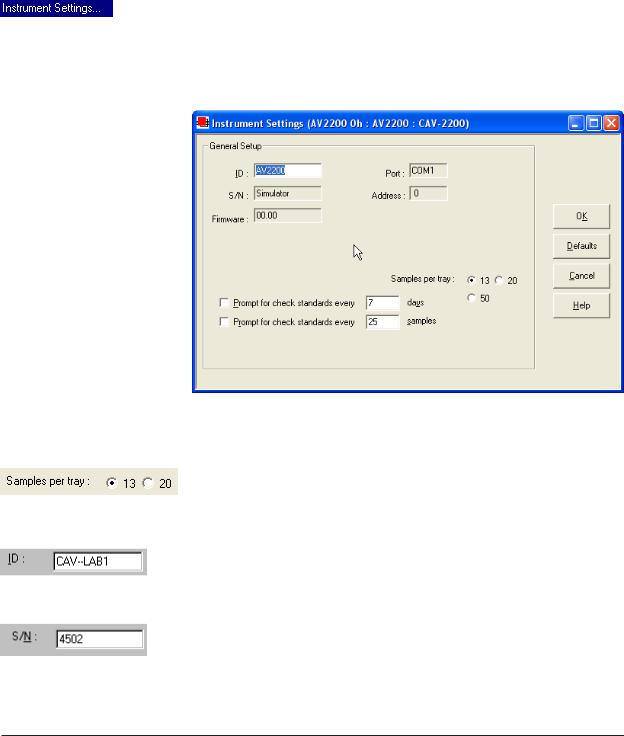
You will use the Instrument Settings window (see below) to describe and control CAV instrument operational features. These settings affect the instrument as a whole. Check the instrument settings for your instrument per the instructions below, and make any necessary changes:
The Instrument Settings window
Click the radio button corresponding to the number of sample positions for your sample trays.
Use the ID field to input instrument identification information using up to 16 alphanumeric characters.
The S/N: field (non-editable) indicates the four-digit serial number from the label on the CAV rear service panel.
CANNON® Automatic Viscometer Models CAV-2100 and CAV-2200 with VISCPRO® Instruction & Operation Manual Version 2g — May, 2009; CANNON® Instrument Company
2139 High Tech Road • State College, PA 16803 • USA
10
Prompt options |
The Prompt for Check Standards options permit you to set a computer- |
|
ized “alarm clock” which will pop up a message reminder to run a |
|
calibration standard (using the Verify Known KV viscosity action) based |
|
on the schedule you set with the control. Notice that you can specify a |
|
reminder after “x” number of days and/or “x” number of samples. Click |
|
the check box(es) to enable/disable each reminder. |
|
When you have verified all settings, click OK. |
Viewing/editing setup information
If your instrument has already been set up by a technician, you can use the instructions in this section of the manual to check or, if necessary, change the instrument settings.
1.Click Configure from the VISCPRO® menu bar.
2.Select your instrument gropu and instrument from the list of available instruments.
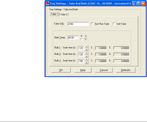
3.Select Tray Settings: Tube and Bath from the list of configuration options. The Tray Settings: Tube and Bath window will appear.
The Tray Settings: Tube and Bath window
The Tray Settings: Tube and Bath window contains setup information for each tube associated with your instrument. You can click on the tube tabs to see the setup information for each tube: 
4. Click on the tube tab for Tube 1 (the tube on the left).
CANNON® Automatic Viscometer Models CAV-2100 and CAV-2200 with VISCPRO® Instruction & Operation Manual Version 2g — May, 2009; CANNON® Instrument Company
2139 High Tech Road • State College, PA 16803 • USA

11
|
5. |
Verify that the tube serial number (Tube S/N) is correct. If it is not, |
|
|
|
input the correct serial number in the text box. Each tube should have |
|
|
|
a unique serial number! |
|
|
6. |
Verify that the calibration values (C and E) for each bulb are avail- |
|
|
|
able. If calibration data is not available, the default values are C=1 |
|
|
|
and E=0. |
|
NOTE |
For first-time installation, make |
|
|
|
certain that the factory-prepared |
|
|
|
Configuration file has been |
|
|
|
copied to the VISCPRO II |
|
|
|
directory per instructions. |
|
|
|
7. |
Compare calibration values |
Sample calibration data |
|
|
to any existing archives of |
|
|
|
|
|
|
|
the calibration constants for |
|
|
|
each bulb of Tube 1. The values, which cannot be edited from the |
|
|
|
Tray Settings: Tube and Bath window, should be identical. |
|
|
8. |
Write down the tube and bulb number for any incorrect values. We |
|
|
|
will change these values later, using the Tube Settings: Calibration |
|
|
|
window. |
|
|
9. |
Click on the tube tab for Tube 2 and repeat steps 7-8 above. When |
|
|
|
you are done, click OK to close the Tray Settings: Tube and Bath |
|
|
|
window. |
|
Manually changing tube calibration constants
If you discovered any errors in the values of the calibration constants (see previous section), follow the directions in this section to manually correct them using calibration information previously obtained for your unit. If the calibration values are correct, instrument setup is complete.
NOTE |
This procedure for manually entering/changing calibration constants |
|
|
bypasses the normal calibration procedure. To ensure the most accurate |
|
|
viscosity readings, CANNON® Instrument Company recommends that the |
|
|
instrument be calibrated per the calibration procedure outlined in Chapter |
|
|
3. |
|
|
1. |
Click Configure from the VISCPRO® menu bar. |
|
2. |
Select your instrument from the list of available instruments. |
|
3. |
Select Calibration from the list of configuration options. The |
|
|
Calibration window will appear (see next page). |
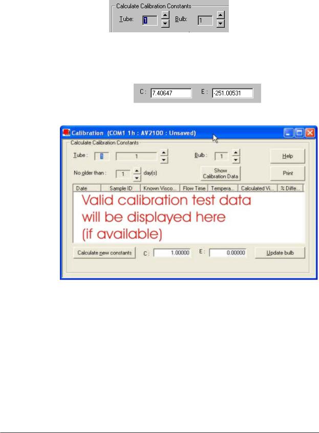
The Calibration window provides controls for calibrating each tube associated with your instrument. You can click on the tube spin controls
 to display current tube constants and valid check standard data available for calibration of each tube.
CANNON® Automatic Viscometer Models CAV-2100 and CAV-2200 with VISCPRO® Instruction & Operation Manual Version 2g — May, 2009; CANNON® Instrument Company
2139 High Tech Road • State College, PA 16803 • USA
12
Procedure
1.Make sure that the spin controls  for Tube and Bulb are both set to “1”:
This corresponds to the left-hand tube in the left-hand bath and the bottom bulb in the tube.
2.Check the values for the calibration constant(s) as they appear at the bottom of the window:
The Calibration window
Compare these values to your archive of the calibration constants (if available) for tube 1 and bulb 1. The values should be identical.
3.If they are not, place your cursor in the appropriate field, delete the entry, then type the correct values for the constants in the text boxes.
4.Click Update bulb.
5.Use the tube and bulb spin controls  to select the tubes/bulbs for which you noted calibration constant errors. Input the correct values for each. Make certain to click Update bulb after you have corrected C and E calibration values for each bulb BEFORE selecting the next tube and/or bulb.
CANNON® Automatic Viscometer Models CAV-2100 and CAV-2200 with VISCPRO® Instruction & Operation Manual Version 2g — May, 2009; CANNON® Instrument Company
2139 High Tech Road • State College, PA 16803 • USA

13
6.When you have entered corrected constant values for each bulb on both tubes, click  to exit the Calibration window.
You have verified the software configuration of VISCPRO®. To test samples with your instrument, follow the instructions in Chapter 2. For additional details regarding operating procedures for your instrument or software, consult the appropriate section of this manual.
CANNON® Automatic Viscometer Models CAV-2100 and CAV-2200 with VISCPRO® Instruction & Operation Manual Version 2g — May, 2009; CANNON® Instrument Company
2139 High Tech Road • State College, PA 16803 • USA

14
This page intentionally left blank.
CANNON® Automatic Viscometer Models CAV-2100 and CAV-2200 with VISCPRO® Instruction & Operation Manual Version 2g — May, 2009; CANNON® Instrument Company
2139 High Tech Road • State College, PA 16803 • USA
15
CHAPTER
2 TESTING SAMPLES WITH THE CANNON AUTOMATIC VISCOMETER
This chapter of the manual will provide information on testing samples using the CAV-2100 or CAV-2200 instruments. Observe the safety cautions noted in the introductory chapter when operating equipment. The CAV should only be operated by qualified personnel.
Preparing the CAV
Turning on the CAV |
1. If CAV power is off, turn on the CAV Bath Unit by rotating the red |
|
power switch on the control panel clockwise. Provide power to the |
|
CSU Service Unit (rear panel On/Off switch) and the Solvent Dis- |
|
pensing Unit (front panel On/Off switch). |
NOTE |
If it is necessary to |
|
cut power to the CAV |
|
Bath Unit, press the |
|
power switch IN. |
Preparing sample trays
Sample trays will slide into place along the grooved track in the sample table. Plated steel vial adaptors should be placed in the circular recesses in the tray.
Glass sample vials slide into the adaptors. To position the first sample vial under the viscometer tube in preparation for testing, slide the tray forward until the detente mechanism engages. A heated sample tray should snap into position against the detent mechanism when the front of the tray extends approximately 2 centimeters (3/4”) over the edge of the sample table. The forward edge of an unheated tray will be indented approximately 2.2 centimeters (7/8”). During sample testing, trays are automatically advanced by the pneumatic system.
Electrical connections |
For heated sample trays, verify that the attached three-pin tray cable is |
|
connected to the interior wall connector above the sample table. |
Using a temperature probe A recessed thermometer well at the front of the sample tray permits insertion of a temperature probe to monitor tray temperature.
CANNON® Automatic Viscometer Models CAV-2100 and CAV-2200 with VISCPRO® Instruction & Operation Manual Version 2g — May, 2009; CANNON® Instrument Company
2139 High Tech Road • State College, PA 16803 • USA

16
Tray/drain heat operations To provide power to the heated sample trays and/or heated drain lines which may be installed on your CAV unit, use the heater ON/OFF switches on the left side of the front panel. These two switches provide power to leftand right-hand heating elements. To adjust temperature, use the Adjust knobs on the upper front panel of the Bath Unit. Turn the knobs clockwise to increase temperature and counterclockwise to lower it. The knobs regulate the duty cycle of the heaters for the sample trays and the drain lines. The low-temperature sample heaters will maintain temperature stability as high as 80°C. The high-temperature sample heaters will maintain temperature stability as high as 100°C.


 CAUTION Avoid skin contact with heated sample trays, as burns may result. Use appropriate protection when handling heated samples, vial adaptors, and sample trays.
Inserting/removing the CAV reference thermometer
Inserting the thermometer
Thermometer
Cable
Connector
Cap
Ferrule
Plug
For additional information and details for CAV thermometer installation/ removal, see Appendix A.
Removing the thermometer
ASTM thermometers with speciallyfitting adaptors for the CAV instrument (see photos) are available from CANNON® Instrument Company. Digital therometers meeting the ASTM D 445 specifcation are also available.
1.To install the reference thermometer, check the current temperature of the CAV bath and select the calibrated thermometer appropriate for that temperature.
2.Using the two opposing 0.05” Allen screws, secure the thermometer
adaptor plate to the connector on the thermometer cable.
3.Using a ladder to access the top of the CAV Bath Unit, remove the knurled cap, ferrule and O-ring from the thermometer holder.
4.Insert the thermometer assembly into the holder until the plug with O-ring is seated inside the top of the holder. Rotate the plug until the thermometer scale is easily visible from the Bath Unit front window.
5.Slide the ferrule over the end of the plug until it seats against the O- ring.
6.Place the knurled cap over the plug and rotate the cap clockwise to secure the cap to the top of the thermometer holder. Tighten finger tight to seal the connection.
To remove the reference thermometer, permit the bath to cool below 80°C and reverse the above procedure. Use appropriate safety procedures when handling the thermometer assembly, as it contains mercury.
CANNON® Automatic Viscometer Models CAV-2100 and CAV-2200 with VISCPRO® Instruction & Operation Manual Version 2g — May, 2009; CANNON® Instrument Company
2139 High Tech Road • State College, PA 16803 • USA

17
Local mode operation
|
The Local mode option permits manual control of CAV functions via the |
|
control keypad on upper front panel of the Bath Unit. Local mode offers |
|
the advantage of convenient and quick testing for an individual sample. |
|
The single-sample drop time or kinematic viscosity is displayed on the |
|
vacuum fluorescent display (VFD). |
NOTE |
The VFD is equipped with a screen saver feature which will reduce the |
|
intensity of the display if the keyboard is not touched for five minutes. To |
|
restore the original intensity of the display, press any key on the keypad. |
Selecting Local mode |
To select Local mode operation, toggle the Remote/Local (RMT/LOC) |
|
button on the keypad on the Bath Unit to select Local mode operation. |
|
When the unit is in Remote mode, the front panel display will indicate |
|
REMOTE operation. If the display does not indicate REMOTE opera- |
|
tion, then the instrument is in Local mode. |
NOTES |
Local mode may be selected at any time during CAV operation. Remote |
|
operations will be suspended. When switching from Remote to Local |
|
mode, it is the user’s responsibility to monitor the instrument tube |
|
state(s) and to properly prepare the instrument before running tests. |
|
Operator intervention is required to test each sample in Local mode. |
|
Additionally, test data is not saved to the VISCPRO® database and |
|
viscosity calculations must be performed manually. |
Setting temperature
 WARNING
NOTE
Prior to setting the bath temperature, ensure that the reference thermometer in the bath is suitable for the desired temperature range. If not, remove thermometer from the bath (see previous page). If the bath temperature rises above the range of the thermometer, it may be damaged. Mercury thermometers pose particular problems, since mercury from a damaged thermometer may circulate with bath fluid.
To set the temperature in Local mode, press the Set Temp key on the front panel keypad, select the desired bath (CAV-2200 only) and input the target (desired) temperature(s) using the keypad characters. Then press the Enter key. Acceptable values are any numbers between 20°C and 100°C (150°C for high-temperature CAV models). If necessary, you may use the decimal point key to input temperature to the nearest 0.01°C.
To cancel temperature selection before completing the procedure, press the Set Temp key a second time.
After the target temperature has been set, the CAV bath temperature will be adjusted to the target temperature and the bath will equilibrate at the test temperature. When the instrument has attained a temperature within
CANNON® Automatic Viscometer Models CAV-2100 and CAV-2200 with VISCPRO® Instruction & Operation Manual Version 2g — May, 2009; CANNON® Instrument Company
2139 High Tech Road • State College, PA 16803 • USA

18
0.05°C of the target temperature, the current bath temperature will be displayed in large type (CAV-2100 only) on the display.
Preparing the bath
|
When operating in Local mode, visually check the condition of the |
|
viscometer tubes prior to initiating a sample run. If sample or solvent |
|
residue remains in the tube, use the Local mode options to wash and/or |
|
dry the tubes (see Chapter 5, Solvent wash by operator (Local mode)). |
Testing samples |
1. Pour the test sample into a glass vial and slide the vial into the steel |
|
|
|
vial adaptor in the sample tray. |
NOTE |
Do not fill the vials to the top. Sample overflow may damage the seals of |
|
the LOAD cylinder. |
|
2. Position the vial directly underneath the viscometer tube, using the |
|
detente mechanism as a guide in orienting the sample. A heated |
|
sample tray should snap into position against the detent mechanism |
|
when the front of the tray extends approximately 2 centimeters (3/4”) |
|
over the edge of the sample table. The forward edge of an unheated |
|
tray will be indented approximately 2.2 centimeters (7/8”). |
|
3. Press the Test button. |
|
4. Select the desired tube for testing (Left (1) or Right (2)). |
|
5. Select the desired protocol for the sample drop: |
|
Run (Determine Bulb) will calculate the optimal test bulb. |
|
Run (Use Previous Bulb) will test the sample using the same bulb |
|
as the previous test (this option is desirable when averaging multiple |
|
drop times for the same sample). |
|
The sample will be tested and the drop time and/or kinematic viscos- |
|
ity (see next page) will be indicated on the VFD. |
|
6. After the test has been completed, you may rerun the sample using |
|
the above procedure, or wash the tube using the keypad WASH |
|
option (see pages 18-19 for details on keypad options). |
Aborting a test |
To immediately halt testing for a given tube/tray (left/right), press the |
|
|
|
Stop Left and/or Stop Right button on the keypad. On rare occasions |
|
when it is necessary to quickly abort tests on both tubes and remove |
|
power from the unit, press the red power button on the control panel. |
NOTE |
Aborting a test using either method clears all sample test information for |
|
that tray. If test actions are aborted, it is the responsibility of the user to |
|
restore the instrument to a safe state before running tests (see Local |
|
mode diagnostics/maintenance in chapter 5 for more information). |
CANNON® Automatic Viscometer Models CAV-2100 and CAV-2200 with VISCPRO® Instruction & Operation Manual Version 2g — May, 2009; CANNON® Instrument Company
2139 High Tech Road • State College, PA 16803 • USA

19
Concluding a test
At the conclusion of a test, the drop time for the sample will be displayed on the display screen. Record the drop time and press the Enter key to return to the temperature display. Then remove the sample from the tray.
CAUTION Use appropriate procedures when handling heated sample trays and 
 heated samples to avoid the possibility of burns.
Empty the oil from the sample vials into the appropriate container(s) for use/disposal and clean glass vials per approved laboratory procedures.
Wipe any excess oil from the table, sample tray and vial holders (glass vials only) using an absorbent paper towel. If necessary, clean these items by wiping with a paper towel wetted with appropriate solvent.
Obtaining kinematic viscosity (KV) readings in Local mode
Local/Remote operation of the CAV is selected via the RMT/LOC button on the CAV keypad. Local mode operation involves CAV control via the keypad. Remote operation involves CAV control via the VISCPRO software interface. Pressing the RMT/LOC button on the CAV keypad will toggle between the Remote and Local operation modes. To obtain kinematic viscosity readings in local mode with the CAV 2000 Series instrument, calibrate each bulb for each bath at the desired bath temperature using VISCPRO II with the instrument set in REMOTE mode.
|
After calibration, open the Tray Settings: Tube and Bath window for |
|
the desired instrument. Make sure the settings are correct and close the |
|
window by clicking the OK button. This action will transmit the bath |
|
temperature(s), the soak times, and the current bulb calibration constants |
|
to the instrument. |
|
Press the RMT/LOC button on the CAV keypad to change the instrument |
|
mode to LOCAL. Then press the Menu button on the CAV instrument. |
|
On the screen, select option #7: Display KV : YES/NO. Toggle the #7 |
|
button to select the desired option. If YES is selected, the KV will be |
|
displayed at the end of a test. |
NOTE |
If the instrument is set to display KV, it will only display KV if the tube |
|
calibration constants have been loaded as described above; otherwise, it |
|
will display the efflux time. If multiple drops are required for a result, the |
|
customer will need to average the KVs resulting from each drop. |
Other Local mode keypad options
The Local mode keypad options described above are the more common functions available. The Keypad Options table (see next pages) contains a list of all Local mode keypad options, including entry parameters and (where applicable) default instrument settings.
NOTES |
Any incomplete keypad command sequence may be cancelled by |
|
pressing the keypad button that initiated the sequence. |
CANNON® Automatic Viscometer Models CAV-2100 and CAV-2200 with VISCPRO® Instruction & Operation Manual Version 2g — May, 2009; CANNON® Instrument Company
2139 High Tech Road • State College, PA 16803 • USA

20
Acceptable keypad input is indicated audibly with a short beep. Unacceptable keypad input is indicated audibly with a longer tone.
Remote operation (computer-controlled)
Local/Remote operation of the CAV is selected via the RMT/LOC button on the control panel. Pressing the button will toggle between the Remote and Local operation modes. The Remote mode option permits automatic control of CAV functions via the VISCPRO® controlling software.
Remote mode offers the advantage of multi-drop, multi-sample automatic testing for up to 100 samples depending on tray type. Sample data is automatically stored to the VISCPRO® database for future reporting/data collection. Additionally, several reports (analyses) may be used to calculate and display kinematic viscosity and viscosity index (VI) values. See the chapters on VISCPRO® analyses for further information.
All analyses provide a dynamic operation mode which can immediately display and transmit test results to your computer screen, printer, and/or serial port for in-house data collection. See Chapter 6 for more information on configuring analyses.
To select Remote mode operation, press the Remote/Local (RMT/LOC) button on the keypad on the Bath Unit until the front panel vacuum fluorescent display indicates REMOTE operation. If the display does not indicate REMOTE operation, then the instrument is in Local mode.
NOTE |
Remote mode may only be selected when the CAV is idle. |
Setting temperature
To set the temperature in Remote mode, load the VISCPRO® software and click Configuration. Select the CAV from the list of available instruments and click Tray Settings: Tube and Bath. Select the desired tube and type the desired temperature in the Bath Temp: field. Acceptable values are any numbers between 20°C and 100°C (150°C for CAV high-temperature models). If necessary, you may use the decimal point key to input temperature to the nearest 0.01°C. Press OK to save the temperature setting.
NOTE |
To cancel temperature selection before completing the procedure, click |
|
Cancel. |
|
After the target temperature has been set, the CAV bath temperature will |
|
be adjusted to the target temperature and the bath will equilibrate at the |
|
test temperature. When the instrument has attained a temperature within |
|
0.05°C of the target temperature, the current bath temperature will be |
|
displayed in large type on the display for CAV-2100 models. |
NOTE |
Placing the instrument in Remote mode while the VISCPRO software is |
|
loaded will reset the bath temperature(s) to match the VISCPRO set- |
|
tings. |
CANNON® Automatic Viscometer Models CAV-2100 and CAV-2200 with VISCPRO® Instruction & Operation Manual Version 2g — May, 2009; CANNON® Instrument Company
2139 High Tech Road • State College, PA 16803 • USA

21
Keypad Options (Local Mode)
|
|
Keypad Command/Description |
|
Parameters |
Default |
|
RMT/LOC |
Changes from Remote to Local mode. Display indicates when in Remote mode. All keypad operations except RMT/LOC and STOP LEFT/RIGHT are invalid in |
|||||
Remote mode. |
|
|
|
|
|
|
|
|
|
|
|
|
|
|
|
|
|
|
|
|
STOP LEFT |
Stops activity for left tube. |
|
|
|
|
|
|
|
|
|
|
|
|
STOP RIGHT |
Stops activity for right tube. |
|
|
|
|
|
|
|
|
|
|
|
|
SET TEMP |
Select bath (CAV-2200 only) and input desired temperature. Then press Enter. |
|
|
|
||
|
|
|
|
|
|
|
MENU |
1) Test Parameters |
1) use left tube |
Bulb[x] Soak Time(s): |
|
0-255 |
120 |
|
|
2) use right tube |
|
|
|
|
|
|
Advanced Parameters |
1) Max Bulb 1 Fill Time(s): |
20-200 |
200 |
|
|
|
|
||||
|
|
|
(restricted) |
|
|
|
|
|
|
2) Min Bulb 1 Select Time(s): |
3.5-20 |
10.5 |
|
|
|
|
|
|||
|
|
|
|
|
|
|
|
|
|
|
3) Min Bulb 2 Fill Time |
0-4 |
1.0 |
|
|
|
|
|
|
|
|
|
|
|
4) Max Bulb Empty Time(s): |
90-600 |
400 |
|
|
|
|
|
|
|
|
|
|
|
5) Max Tube Empty Time(s): |
5-125 |
15 |
|
|
|
|
|
|
|
|
2) Wash Parameters |
1) use left tube |
0) A Wash B1: |
|
0-18 |
11 |
|
|
2) use right tube |
|
Input solvent A/ Bulb "X" wash |
|
|
|
|
1) A Wash B2: |
0-18 |
9 |
||
|
|
|
||||
|
|
|
time. |
|||
|
|
|
|
|
|
|
|
|
Set at "0" for fast run tubes. |
2) A Wash B3: |
|
0-18 |
5 |
|
|
|
|
|
|
|
|
|
|
3) Slv Fill(s): |
Input solvent fill time. |
1-30 |
2 |
|
|
|
|
|
|
|
|
|
|
4) Slv Soak(s): |
Input solvent soak time. |
1-30 |
2 |
|
|
|
|
|
|
|
|
|
NOTE: If using a single solvent only, the |
5) B Wash B1: |
|
0-18 |
9 |
|
|
values for the unused Wash (A or B) |
|
Input solvent B/ Bulb "X" wash |
|
|
|
|
6) B Wash B2: |
0-18 |
5 |
||
|
|
must be set to "0". |
||||
|
|
time. |
||||
|
|
|
|
|
|
|
|
|
Set at "0" for fast run tubes. |
7) B Wash B3: |
|
0-18 |
2 |
|
|
|
|
|
|
|
|
|
|
8) Slv Flush(s): |
Input solvent flush time. |
1-60 |
2 |
|
|
|
|
|
|
|
|
|
|
9) Final Air(s): |
Input air dry time. |
15-255 |
50 |
|
|
|
|
|
|
|
|
3) Temperature Units |
1) °F |
Use keypad buttons to select desired units. |
°F/°C |
°C |
|
|
2) °C |
|||||
|
|
|
|
|
|
|
|
|
|
|
|
|
|
|
4) Calibrate Temperature |
1) Set Current Temperature Offset |
Use keypad buttons to input temperature from reference |
|
|
|
|
|
thermometer to the nearest 0.01°. Then press ENTER |
N/A |
N/A |
||
|
|
|
button. |
|
|
|
|
|
|
|
|
|
|
|
|
2) Zero Current Temperature Offset |
The current temperature offset will be cleared. ENTER to |
N/A |
N/A |
|
|
|
accept. MENU to cancel. |
|
|||
|
|
|
|
|
|
|
|
|
|
|
|
|
|
|
|
1) Train left tube sensors |
Initiates automatic sensor training procedure. Display will |
|
|
|
|
5) Train Sensors |
2) Train right tube sensors |
indicate IDLE when training is completed. |
|
|
|
|
3) Train all sensors |
Initiates sensor adjustment using sample in the vial under |
N/A |
N/A |
||
|
|
4) Adjust Left Tube Trip Pts. |
the viscometer tube. |
|
|
|
|
|
5) Adjust Right Tube Trip Pts. |
|
|
|
|
|
|
|
|
|
|
|
|
6) Service |
1) Instrument Address |
Input unique value for each Bath Unit. |
0-9 |
0 |
|
|
|
|
|
|
|
|
|
|
2) Communications Type |
1) RS-485 |
Input connection type. |
N/A |
RS-232 |
|
|
2) RS-232 |
||||
|
|
|
|
|
|
|
|
|
|
|
|
|
|
|
|
3) Status |
Displays voltages and settings for instrument diagnostics |
|
N/A |
|
|
|
|
|
|
|
|
|
|
|
|
1) Manual Fill |
Press to raise cup. Hold "1" |
|
|
|
|
1) Use Left Tube |
key down to draw liquid into |
||
|
|
4) Manual Tube Fill |
|
tube. Release key to drain. |
||
|
|
2) Use Right Tube |
|
|
|
|
|
|
|
2) Cup Down |
Press to lower cup. |
||
|
|
|
|
|||
|
|
|
|
Liquid will drain. |
||
|
|
|
|
|
||
|
|
|
|
|
|
|
|
|
5) Password |
Input password from CANNON Instrument Company to access restricted |
N/A |
||
|
|
options. |
|
|
||
|
|
|
|
|
|
|
|
7) Display KV: YES/NO |
Press Enter to toggle YES/NO options |
|
|
|
|
|
|
|
|
|
|
|
TEST |
1) use left tube |
1) Run (Determine Bulb) |
|
|
|
|
2) use right tube |
2) Run (Use Previous Bulb) |
|
|
|
|
|
|
|
|
|
|
||
|
|
|
|
|
|
|
WASH |
1) use left tube |
Washes viscometer tube using Wash parameters. |
|
|
|
|
2) use right tube |
|
|
|
|||
|
|
|
|
|
|
|
DRY |
1) use left tube |
Dries viscometer tube using Wash parameters. |
|
|
|
|
2) use right tube |
|
|
|
|||
|
|
|
|
|
|
|
ENTER |
Used to input numeric data. Press ENTER upon completion of data entry to accept input values. |
|
|
|
||
|
|
|
|
|
|
|
0, 1, 2, 3, 4, 5, |
Used to input numeric data. Press ENTER upon completion of data entry to accept input values. |
|
|
|
||
6, 7, 8, 9, . |
|
|
|
|
|
|
CANNON® Automatic Viscometer Models CAV-2100 and CAV-2200 with VISCPRO® Instruction & Operation Manual Version 2g — May, 2009; CANNON® Instrument Company
2139 High Tech Road • State College, PA 16803 • USA

22
Testing samples
Loading software |
1. Turn on the computer and load the CAV software by double-clicking |
|
the VISCPRO® icon on the Desktop. |
NOTES |
If the software is already loaded, use your computer mouse to click Main |
|
from the menu bar and click Poll for Instruments from the Main menu |
|
options. This will establish communications between the computer and |
|
the on-line instrument. |
|
Permit the bath(s) to stabilize at test temperature before testing samples. |
|
2. Pour sample material into the glass vial(s). Fill to within 1.3 cm (½”) |
|
of the top of each vial (somewhat less sample may be required for |
|
testing in lower bulbs of the viscometer). Insert the glass vials into |
|
the steel carrier cylinders and place the cylinders into the sample tray. |
NOTES |
Do not fill the vials to the top. Sample overflow may damage the seals of |
|
the LOAD cylinder. You should run calibration check standards per your |
|
established laboratory procedures. Recalibrate the CAV (see Chapter 3, |
|
Calibration) if result variance warrants. |
3.Place the sample tray into the track underneath the viscometer tube. Push the sample tray forward until the first vial is under the viscometer tube. A heated sample tray should snap into position against the detent mechanism when the front of the tray extends approximately 2 centimeters (3/4”) over the edge of the sample table. The forward edge of an unheated tray will be indented approximately 2.2 centimeters (7/8”).
4.Ensure that the splash guard(s) in front of the viscometer tube has been secured in place with the thumbscrew. If a splash guard has been removed, replace it.
!CAUTION The splash guard(s) may be removed to allow the user to handle the
sample not yet running (replace with a different sample, etc.). However, make certain to return the splash guard to its proper position to prevent sample/solvent contamination and to protect the viscometer tube tip. Do not allow your hands to contact or obstruct the pneumatic mechanism or heated sample trays and electrical connections.
5.Check the thermometer in the temperature bath to make sure the bath is holding the proper temperature. If necessary, calibrate the CAV temperature control probe using the temperature calibration procedure in Chapter 3.
6.Open the View Instrument Group window (if it is not already open) by clicking View Instrument from the Main menu and selecting the desired instrument group from the list box (see Chapter 4 for more information).
CANNON® Automatic Viscometer Models CAV-2100 and CAV-2200 with VISCPRO® Instruction & Operation Manual Version 2g — May, 2009; CANNON® Instrument Company
2139 High Tech Road • State College, PA 16803 • USA

23
The View Instrument Group window
7. Click OK to display the Sample Input View for the desired group:
The Sample Input window
Then click the Tray tab corresponding with the desired viscometer tube.
8.Double-click on Sample ID (1) with the left mouse button to access the sample ID data entry field (or press 2).
9.Enter sample ID information in the sample list box using your
computer keyboard. After you have typed the sample ID, press the Tkey to save the entry and move the cursor to the next Sample ID field. Or press Rto save the entry.
CANNON® Automatic Viscometer Models CAV-2100 and CAV-2200 with VISCPRO® Instruction & Operation Manual Version 2g — May, 2009; CANNON® Instrument Company
2139 High Tech Road • State College, PA 16803 • USA

24
NOTE |
Once sample information is entered, the software automatically assigns |
|
a sample action, Measure Sample Viscosity, for the sample. If you do not |
|
enter a sample ID, the sample is automatically labeled Unknown. |
|
To select or change a sample action, highlight the appropriate Sample |
|
ID(s) using the mouse or arrow keys, then click the RIGHT mouse |
|
button to access sample action options: |
|
Then you may select the desired action by highlighting it and click- |
|
ing the left mouse button. |
NOTE |
For additional information on software data entry features, including |
|
multiple sample selection and cut & paste options, see Testing |
|
samples—software options in Chapter 4. |
Running check standards |
If Verify Known KV is selected as the test option for a sample, the |
|
Viscosity Action window will open automatically. Enter the neces- |
|
sary check standard data, including the Check Standard viscosity |
|
from the standard bottle, and click OK to complete data entry. To |
|
revise or confirm standard data, right-click on the desired sample ID |
|
from the list box and select Configure from the popup menu choices. |
NOTE |
See Chapter 4 for additional information on the Viscosity Action window. |
|
10. Continue entering sample information for all desired trays. When |
|
sample ID data entry is complete, check the Tray Status window to |
|
verify that all trays are ready for testing. |
|
11. Click on the RUN button at the bottom of the Sample Input win- |
|
dow. The Select Trays window will open. |
|
12. Click on the check box(es) to select the desired prepared tray(s) for |
|
automatic testing. Then click OK to begin the CAV test(s). |
Pausing a test |
To temporarily halt testing for a given tube/sample, click the Pause |
|
|
|
button from the Sample Input window. Then select the desired tray(s) |
|
and pause action(s) from the Select Trays window (Pause Now will |
|
immediately pause test actions; Pause after current sample will pause |
|
testing after the current test is complete). Click OK to pause testing for |
|
the selected tray(s). |
NOTE |
If the test was paused prior to the initiation of the Wash cycle, drop time |
|
data for that sample will be discarded. |
CANNON® Automatic Viscometer Models CAV-2100 and CAV-2200 with VISCPRO® Instruction & Operation Manual Version 2g — May, 2009; CANNON® Instrument Company
2139 High Tech Road • State College, PA 16803 • USA
 Loading...