

Page 1
Stationary Air Compressors
Operating Instructions and Parts Manual
© 2016 Campbell Hausfeld
A Marmon/Berkshire Hathaway Company
Models: VT6195 and VT6395
EN
IN571500AV 6/16
Page 2

Please read and save these instructions. Read carefully before attempting to
assemble, install, operate or maintain the product described.
Protect yourself and others by observing all safety information. Failure to comply
with instructions could result in personal injury and/or property damage! Retain
instructions for future reference.
REMINDER: Keep your dated proof of purchase for warranty purposes! Attach it to
this manual or file it for safekeeping.
For parts, product & service information
Model #: __________________________
Serial #: ___________________________
Purchase Date: _____________________
REGISTER YOUR PRODUCT ONLINE NOW! www.campbellhausfeld.com
READ AND FOLLOW ALL INSTRUCTIONS • SAVE THESE INSTRUCTIONS • DO NOT DISCARD
visit www.campbellhausfeld.com
Campbell Hausfeld
100 Production Drive
Harrison, Ohio 45030
Page 3
BEFORE YOU BEGIN
Introduction
Air compressor units are intended to provide compressed air to power pneumatic tools, operate spray guns
and supply air for pneumatic valves and actuators. The pumps supplied with these units have oil lubricated
bearings. A small amount of oil carryover is present in the compressed air stream. Applications requiring air
free of oil vapor should have the appropriate filters installed. The air compressor units are to be mounted
per the instructions provided on a solid floor. Any other use of these units will void the warranty and the
manufacturer will not be responsible for problems or damages resulting from such misuse.
QUICK REFERENCE
Recommended Oil (2 Options)
Single viscosity SAE 30 ISO100 nondetergent compressor oil. Part number ST125303AV (0.5
qt) or ST126701AV (4 qt).
10W30 synthetic oil such as Mobil 1
Oil Capacity
Approximately 8.5 oz.
UNPACKING
Do not lift or move unit without appropriately rated equipment. Be sure
coolers. Do not use unit to lift other attached equipment.
After unpacking the unit, inspect carefully for any damage that may have occurred during transit. Check for
loose, missing or damaged parts. Check to be sure all supplied accessories are enclosed with the unit. In case
of questions, damaged or missing parts, please visit www.campbellhausfeld.com for customer assistance.
Do not operate unit if damaged during shipping, handling or use. Damage
®
or CE0032 (1 qt).
the unit is securely attached to lifting device used. Do not lift unit by holding onto tubes or
may result in bursting and cause injury or property damage.
GETTING STARTED
SPECIFICATIONS
SAFETY /
INSTALLATION
ASSEMBLY /
Required Items - Not Included
• Oil
TROUBLESHOOTINGOPERATION
MAINTENANCE /
REPAIR
1
Page 4
SAFETY /
GENERAL SAFETY INSTRUCTIONS
Safety Guidelines
This manual contains information that is very important to know and understand. This information is
GETTING STARTED
SPECIFICATIONS
provided for SAFETY and to PREVENT EQUIPMENT PROBLEMS. To help recognize this information, observe
the following symbols.
Danger indicates an imminently hazardous situation which, if not avoided, WILL result in death
Warning indicates a potentially hazardous situation which, if not avoided, COULD result in
Caution indicates a potentially hazardous situation which, if not avoided, MAY result in minor
IMPORTANT: Information that requires special attention.
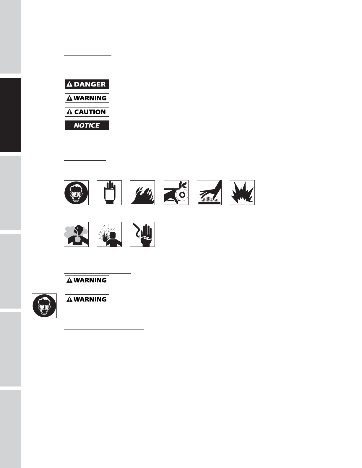
Safety Symbols
The following Safety Symbols appear throughout this manual to alert you to important safety hazards and
precautions.
or serious injury.
death or serious injury.
or moderate injury.
Notice indicates important information, that if not followed, may cause damage to equipment.
MANUAL
ASSEMBLY /
INSTALLATION
TROUBLESHOOTING OPERATION
Wear Eye
and Mask
Protection
Risk of
Fumes
Read
Manual
First
Risk of
Pressure
Risk of
Fire
Risk of Shock
Risk of
Moving Parts
Risk of
Hot Parts
Risk of
Explosion
California Proposition 65
This product or its power cord may contain chemicals known to the State
handling.
You can create dust when you cut, sand, drill or grind materials such as wood,
cause cancer, birth defects, or other reproductive harm. Wear protective gear.
of California to cause cancer and birth defects or other reproductive harm. Wash hands after
paint, metal, concrete, cement, or other masonry. This dust often contains chemicals known to
Important Safety Information
Please read and save these instructions. Read carefully before attempting to assemble, install, operate or maintain the
product described. Protect yourself and others by observing all safety information. Failure to comply with instructions
could result in personal injury and/or property damage! Retain instructions for future reference.
This manual contains important safety, operational and maintenance information. If you have any
questions, please visit www.campbellhausfeld.com for customer assistance.
Since the air compressor and other components (material pump, spray guns, filters, lubricators, hoses, etc.)
used make up a high pressure pumping system, the following safety precautions must be observed at all
times:
REPAIR
MAINTENANCE /
2
Page 5
MANUAL
Important Safety Information (Continued)
BREATHABLE AIR WARNING
This compressor/pump is not equipped and should not be used “as is” to supply breathing quality
air. For any application of air for human consumption, the air compressor/pump will need to be
fitted with suitable in-line safety and alarm equipment. This additional equipment is necessary to
properly filter and purify the air to meet minimal specifications for Grade D breathing as described in
Compressed Gas Association Commodity Specification G 7.1, OSHA 29 CFR 1910. 134, and/or Canadian
Standards Associations (CSA).
DISCLAIMER OF WARRANTIES
In the event the compressor is used for the purpose of breathing air application and proper in-line
safety and alarm equipment is not simultaneously used, existing warranties shall be voided, and the
manufacturer disclaims any liability whatsoever for any loss, personal injury or damage.
General Safety
• Read all manuals included with this product carefully. Be thoroughly familiar with the controls and the
proper use of the equipment.
• Follow all local electrical and safety codes as well as the United States National Electrical Codes (NEC)
and Occupational Safety and Health Act (OSHA).
• Only persons well acquainted with these rules of safe operation should be allowed to use the
compressor.
• Keep visitors away and NEVER allow children in the work area.
• Wear safety glasses and use hearing protection when operating the unit.
• Do not stand on or use the unit as a handhold.
• Before each use, inspect compressed air system and electrical components for signs of damage,
deterioration, weakness or leakage. Repair or replace defective items before using.
• Check all fasteners at frequent intervals for proper tightness.
Motors, electrical equipment and controls can cause electrical arcs that will ignite a flammable
gas or vapor. Never operate or repair in or near a flammable gas or vapor. Never store
flammable liquids or gases in the vicinity of the compressor.
Never operate compressor without a beltguard. This unit can start automatically without
warning. Personal injury or property damage could occur from contact with moving parts.
• Do not wear loose clothing or jewelry that will get caught in the moving parts of the unit.
GETTING STARTED
SPECIFICATIONS
SAFETY /
INSTALLATION
ASSEMBLY /
Compressor parts may be hot even if the unit is stopped.
• Keep fingers away from a running compressor; fast moving and hot parts will cause injury and/or burns.
• If the equipment should start to vibrate abnormally, STOP the engine/motor and check immediately for
the cause. Vibration is generally an indication of trouble.
• To reduce fire hazard, keep engine/motor exterior free of oil, solvent, or excessive grease.
An ASME code safety relief valve with a setting no higher than the Maximum Allowable
this compressor. The ASME safety valve must have sufficient flow and pressure ratings to protect the pressurized
components from bursting. The flow rating can be found in the parts manual.
Maximum operating pressure is 135 psi for single stage compressors. Do not operate with
Working Pressure (MAWP) of the tank MUST be installed in the air lines or in the tank for
See compressor specifications for maximum operating pressure. Do not operate with pressure switch
or pilot valves set higher than the maximum operating pressure.
pressure switch or pilot valves set higher than 135 psi (single stage).
• Never attempt to adjust ASME safety valve. Keep safety valve free from paint and other accumulations.
3
TROUBLESHOOTINGOPERATION
MAINTENANCE /
REPAIR
Page 6

GETTING STARTED
Important Safety Information (Continued)
Never use plastic (PVC) pipe for compressed air. Serious injury or death could
Never attempt to repair or modify a tank! Welding, drilling or any other modification will
or damaged tanks.
• Tanks rust from moisture build-up, which weakens the tank. Make sure to drain tank regularly and
inspect periodically for unsafe conditions such as rust formation and corrosion.
• Fast moving air will stir up dust and debris which may be harmful. Release air slowly when draining
moisture or depressurizing the compressor system.
result.
weaken the tank resulting in damage from rupture or explosion. Always replace worn, cracked
Drain liquid from tank daily.
SAFETY /
ASSEMBLY /
SPECIFICATIONS
INSTALLATION
Spraying Precautions
Do not spray flammable materials in vicinity of open flame or near ignition sources including
the compressor unit.
• Do not smoke when spraying paint, insecticides, or other flammable substances.
• Use a face mask/respirator when spraying and spray in a well ventilated area to prevent health and fire
hazards.
• Do not direct paint or other sprayed material at the compressor. Locate compressor as far away from
the spraying area as possible to minimize overspray accumulation on the compressor.
• When spraying or cleaning with solvents or toxic chemicals, follow the instructions provided by the
chemical manufacturer.
Save These Instructions
Do Not Discard
The DANGER, WARNING, CAUTION, and NOTICE notifications and instructions in this manual
cannot cover all possible conditions and situations that may occur. It must be understood by the
operator that caution is a factor which cannot be built into this product, but must be supplied by the
operator.
MAINTENANCE /
TROUBLESHOOTING OPERATION
REPAIR
4
Page 7
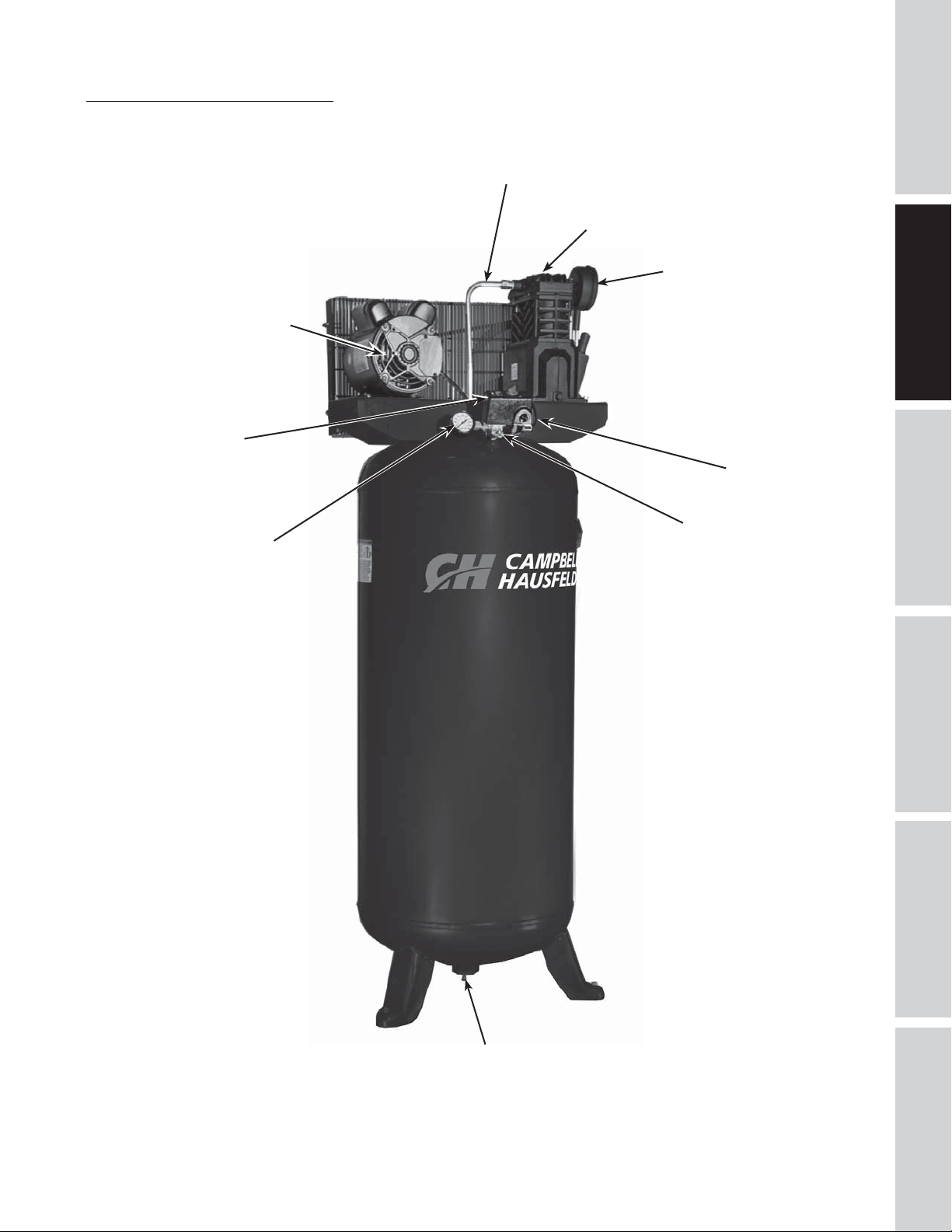
Getting To Know Your Compressor
Motor
Pressure Switch
Discharge Tube
Compressor Pump
Air Filter
Unloader Tube
GETTING STARTED
SPECIFICATIONS
SAFETY /
INSTALLATION
ASSEMBLY /
Tank Pressure
Gauge
Safety Relief Valve
TROUBLESHOOTINGOPERATION
Figure 1 - Vertical Unit Identification
Manual Tank Drain
5
MAINTENANCE /
REPAIR
Page 8
SAFETY /
SPECIFICATIONS
Motor HP 3.7
Power 208-230V
GETTING STARTED
SPECIFICATIONS
Phase 1
Displacement CFM 12.2
Air Delivery CFM @ 90 PSI 10.2
Air Delivery CFM @ 135 PSI 9.8
Max PSI 135
Pump RPM 1020
Tank Capacity 60 gallons
Unit Weight 255 lbs
Amp Draw 14.5
Max Duty Cycle 75%
Tank Outlet 3/4 in. NPT
Tank MAWP 175 PSI
DIMENSIONS
VT6195 & VT6395
ASSEMBLY /
INSTALLATION
Length 23 inches
Width 25 inches
Height 66 inches
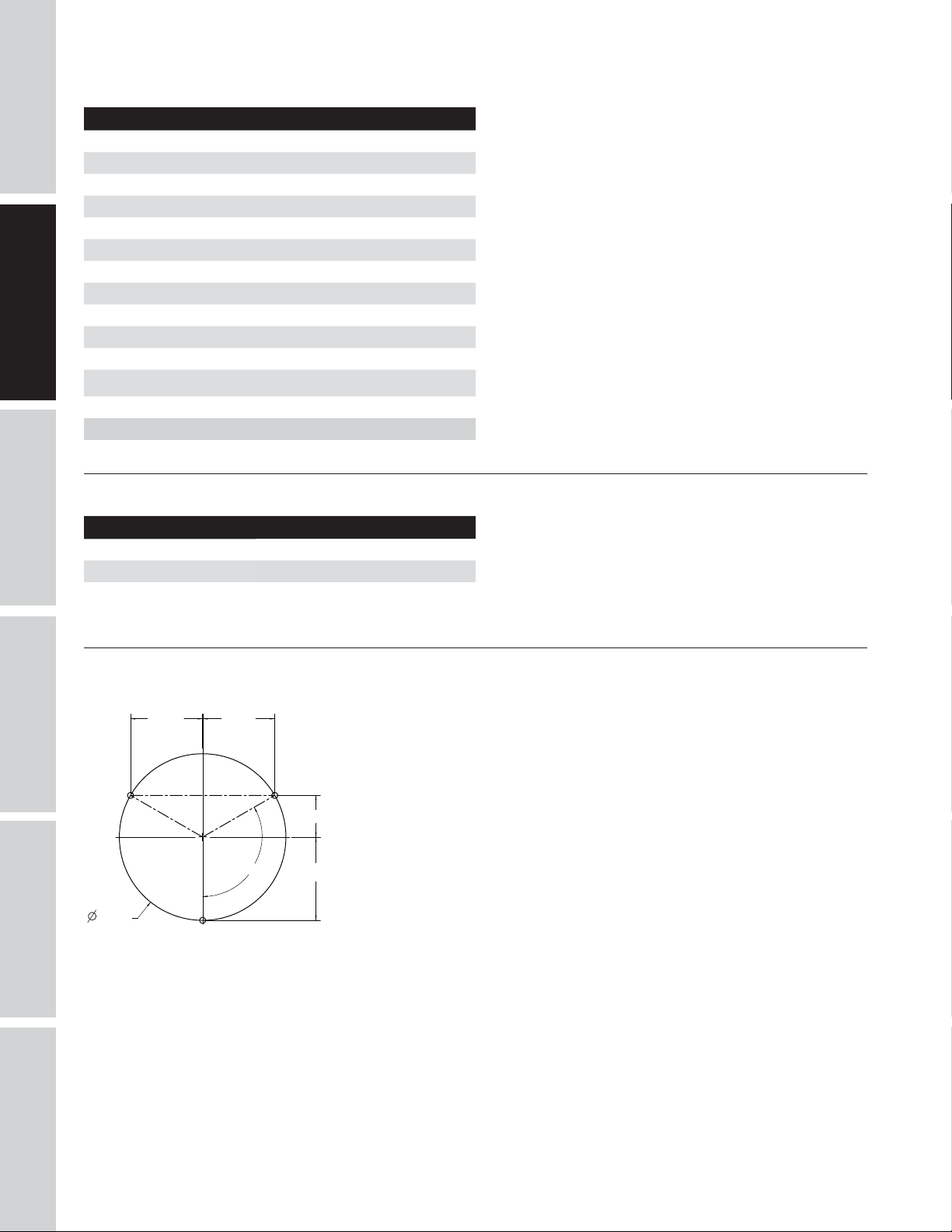
BOLT DOWN PATTERN
10.39
in.
24.00
TROUBLESHOOTING OPERATION
VT6195 & VT6395
in.
10.39
120.00
in.
6.0
in.
o
12
in.
REPAIR
MAINTENANCE /
6
Page 9
INSTALLATION INSTRUCTIONS
GETTING STARTED
Disconnect, tag and lock out power source then release all pressure from the system before
Do not lift or move unit without appropriately rated equipment. Be sure the unit is securely
to lift other attached equipment.
attempting to install, service, relocate or perform any maintenance.
attached to lifting device used. Do not lift unit by holding onto tubes or coolers. Do not use unit
Never use the wood shipping skids for mounting the compressor.
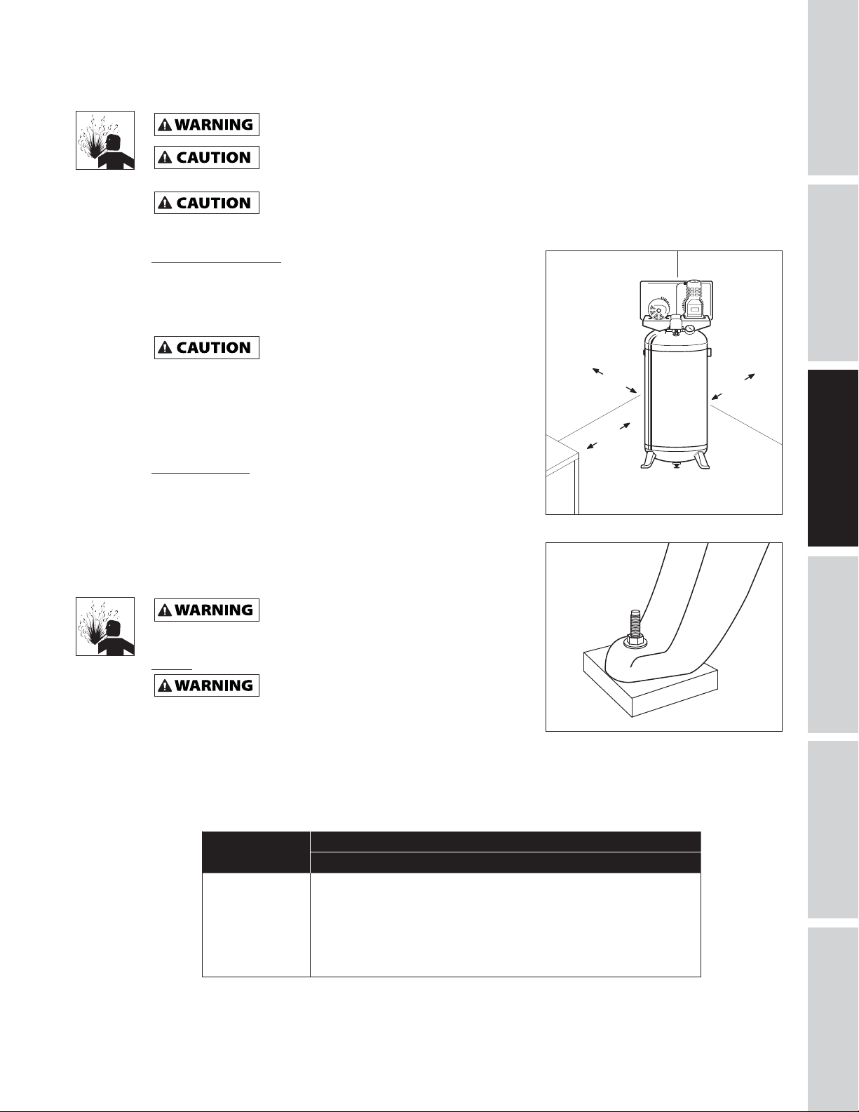
Picking the Location
Install and operate unit at least 18 inches from any obstructions
in a clean, well ventilated area. The surrounding air temperature
should not exceed 100° F. This will ensure an unobstructed flow of
air to cool compressor and allow adequate space for maintenance.
Do not locate the compressor air inlet
other source of contamination.
NOTE: If compressor operates in a hot, moist environment, supply
compressor pump with clean, dry outside air. Supply air should be
near steam, paint spray, sandblast areas or any
≥ 18
inches
≥ 18
inches
piped in from external sources.
≥ 18
inches
Tank Mounting
The tank should be bolted into a flat, even, concrete floor or on a
separate concrete foundation. Vibration isolators should be used
between the tank leg and the floor. Model MP345700AJ isolator
pads are recommended for installation.
When using isolator pads, do not draw bolts tight. Allow the pads
to absorb vibrations. When isolators are used, a flexible hose or
coupling should be installed between the tank and service piping.
Failure to properly install the tank can lead to
cracks at the welded joints and possible bursting.
Figure 2 - Location
SPECIFICATIONS
SAFETY /
INSTALLATION
ASSEMBLY /
Piping
Never use plastic (PVC) pipe for compressed air.
Any tube, pipe or hose connected to the unit must be able to
withstand the temperature generated and retain the pressure.
All pressurized components of the air system must have a
pressure rating of 200 psi or higher. Incorrect selection and
installation of any tube, pipe or hose could result in bursting and injury. Connect piping system to tank
using the same size fitting as the discharge port.
Serious injury or death could result.
Figure 3 - Isolator Pad
Minimum Pipe Size For Compressed Air Line
Length Of Piping System
CFM
10 1/2 inch 1/2 inch 3/4 inch 3/4 inch
20 3/4 inch 3/4 inch 3/4 inch 1 inch
40 3/4 inch 1 inch 1 inch 1 inch
60 3/4 inch 1 inch 1 inch 1 inch
100 1 inch 1 inch 1 inch 1-1/4 inch
25 feet 50 feet 100 feet 250 feet
TROUBLESHOOTINGOPERATION
MAINTENANCE /
REPAIR
7
Page 10
SAFETY /
ASSEMBLY /
INSTALLATION INSTRUCTIONS (CONTINUED)
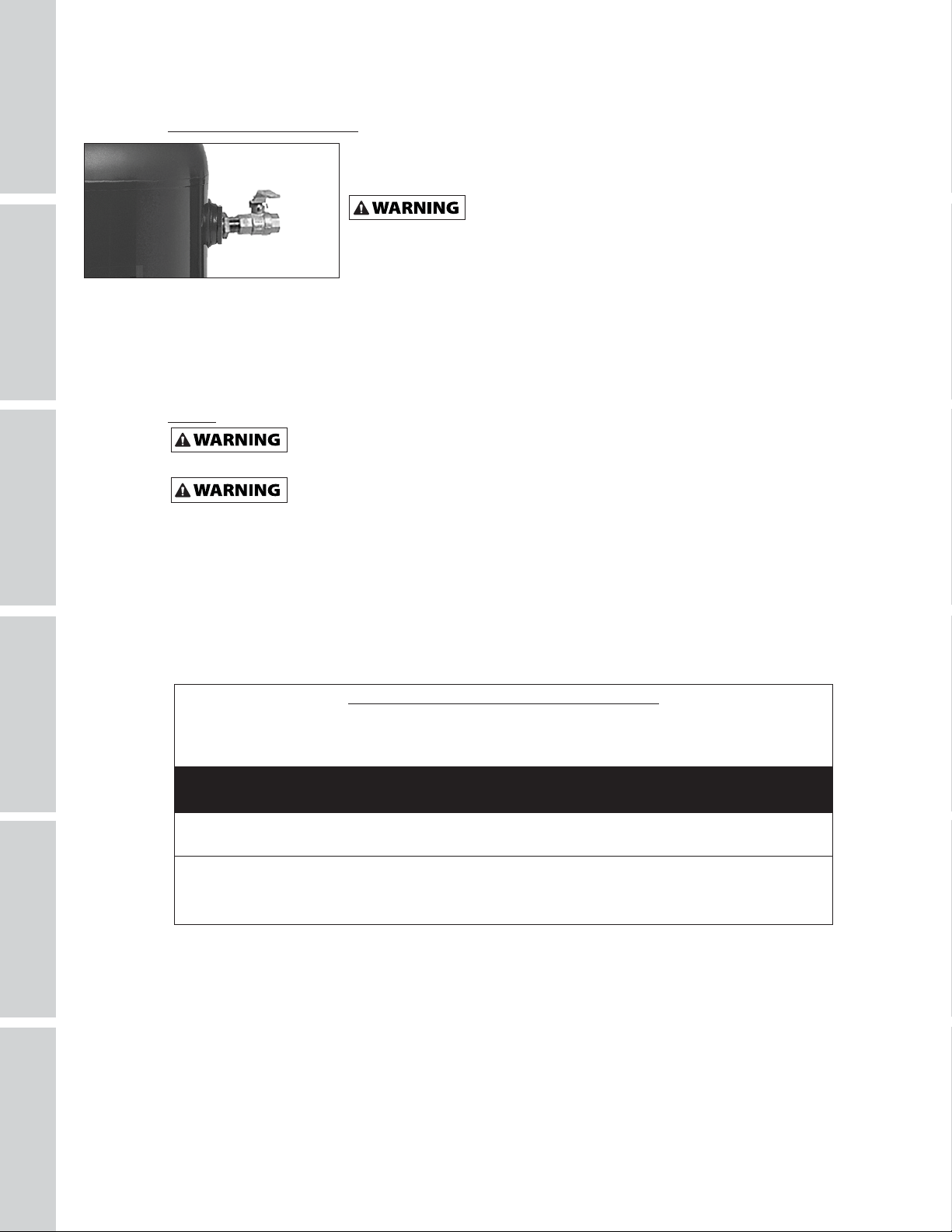
Installing A Shut-Off Valve
A shut-off valve should be installed on the discharge port of the tank to control
the air flow out of the tank. The valve should be located between the tank and
GETTING STARTED
SPECIFICATIONS
INSTALLATION
Figure 4
- Shut-off Valve
Apply air pressure to the piping installation and make sure all joints are free from leaks BEFORE
underground lines are covered. Before putting the compressor into service, find and repair all leaks in the
piping, fittings and connections.
Wiring
All wiring and electrical connections must be performed by a qualified electrician
familiar with induction motor controls. Installations must be in accordance with local and
national codes.
Wiring must be installed in accordance with National Electrical Code and local codes and standards that
have been set up covering electrical apparatus and wiring. These should be consulted and local ordinances
observed. Be certain that adequate wire sizes are used, and that:
1. Service is of adequate ampere rating.
2. The supply line has the same electrical characteristics (voltage, cycles and phase) as the motor. Refer to
motor name plate for electrical ratings and specifications.
3. The line wire is the proper size and that no other equipment is operated from the same line. The chart
gives minimum recommended wire sizes for compressor installations.
the piping system.
Never install a shut-off valve between the compressor pump and
Never use reducers in discharge piping.
When creating a permanently installed system to distribute compressed air,
find the total length of the system and select pipe size from the chart on
page 7. Bury underground lines below the frost line and avoid pockets where
condensation can gather and freeze.
Overheating, short circuiting and fire damage will result from inadequate wiring.
the tank. Personal injury and/or equipment damage may occur.
TROUBLESHOOTING OPERATION
REPAIR
Minimum Wire Size (Use 75°C Copper Wire)
Make sure voltage is correct with the motor wiring.
NOTE: If using 208 volts single phase, make sure the motor name plate states it is rated for 208 volts single
phase. 230 volt single phase motors do not work on 208 volts unless they have the 208 volt rating.
Single Phase
HP Amps 230V
1-4 HP up to 22.0 10 AWG
5.0 8 AWG
Recommended wire sizes may be larger than the minimum set up by local ordinances. If so, the larger size
wire should be used to prevent excessive line voltage drop. The additional wire cost is very small compared
with the cost of repairing or replacing a motor electrically “starved” by the use of supply wires which are too
small.
MAINTENANCE /
8
Page 11
INSTALLATION INSTRUCTIONS (CONTINUED)
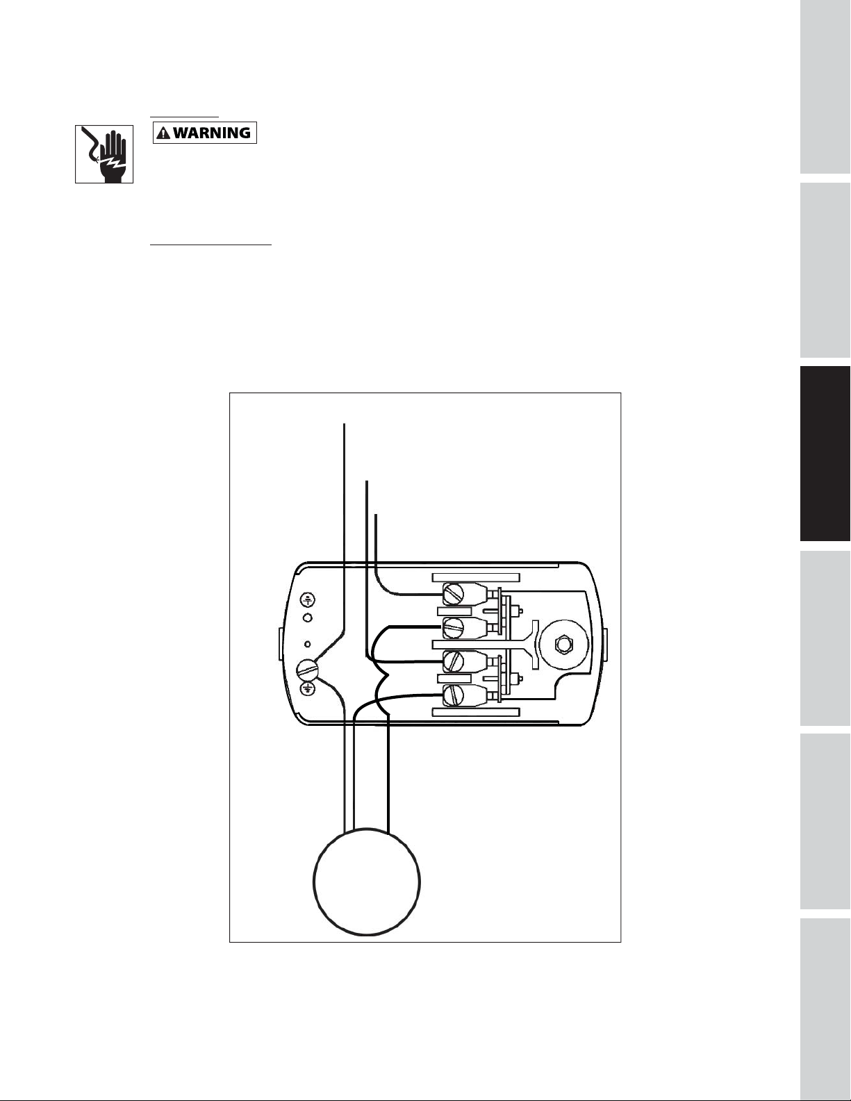
Grounding
Improperly grounded electrical components are shock hazards. Make sure all the
components are properly grounded to prevent death or serious injury.
This product must be grounded. Grounding reduces the risk of electrical shock by providing an escape wire
for the electric current if short circuit occurs. This product must be installed and operated with a power cord
or cable that has a grounding wire.
Breakers and Fuses
The entire electrical system should be checked by a certified electrician. Time delay breakers and fuses are
required for this compressor. A tripped breaker or blown fuses may indicate a direct short to ground, high
current draw, improper wiring, incorrect fuse or breaker size and/or type. This needs to be evaluated by a
certified electrician.
GETTING STARTED
SPECIFICATIONS
SAFETY /
Ground
L1
L2
INSTALLATION
ASSEMBLY /
TROUBLESHOOTINGOPERATION
Motor
Figure 5 - Wiring Diagram
MAINTENANCE /
REPAIR
9
Page 12

INSTALLATION INSTRUCTIONS (CONTINUED)
SAFETY /
ASSEMBLY /
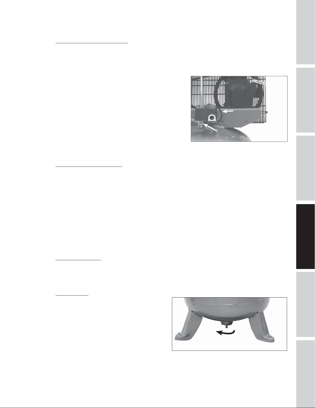
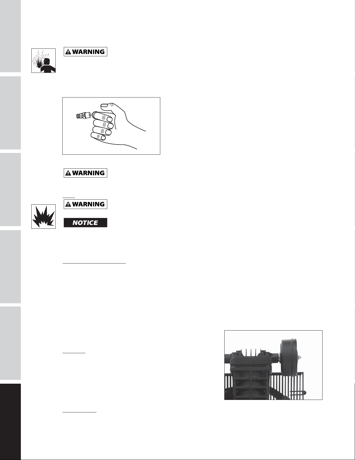
Installing Air Inlet Filter
Screw supplied air inlet filter into inlet port of cast iron
pump as indicated in Figure 6.
GETTING STARTED
Lubrication
This unit contains no oil.
center of the sight gauge (see Figure 6).
Using any other type of oil may
SPECIFICATIONS
Recommended Oil (2 Options)
Single viscosity SAE 30 ISO100 nondetergent compressor oil.
Part number ST125303AV (0.5 qt) or ST126701AV (4 qt).
10W30 synthetic oil such as Mobil 1® or CE0032 (1 qt).
Oil Capacity
Approximately 8.5 oz.
Fill the pump with oil to the center of the sight gauge
using oil fill opening (see Figure 6).
through the breather cap opening as this may cause oil to leak
and spray out during operation.
NOTE: Some residual oil may still be in the pump from
INSTALLATION
factory testing leaving a thin coat on the sight gauge;
however, there is not enough oil to operate the unit.
Before operating compressor, fill to the
shorten pump life and damage valves.
Do NOT fill the pump
Inlet Port
Oil FIll
Area
Oil Drain
Plug
OPERATING INSTRUCTIONS
Important: Check motor rotation before operating the
compressor.
All lubricated compressor pumps discharge some
condensed water and oil with the compressed air. Install
appropriate water/oil removal equipment and controls as
necessary for the intended application.
Failure to install appropriate
water/oil removal equipment may result
in damage to machinery or workpiece.
Guarding
The belt guard provided must be
installed before operating the unit.
All moving parts must be guarded. All electrical covers must
be installed before turning on the power.
TROUBLESHOOTING OPERATION
Full
Low
Sight Gauge
Figure 6 - Lubrication
REPAIR
MAINTENANCE /
10
Page 13
OPERATING INSTRUCTIONS (CONTINUED)
Recommended Break-In Period
The compressor should be run continuously at 90 PSI or lower for one hour to allow proper seating of the
piston rings.
1. Open drain cock completely and run the compressor for 60 minutes.
2. Turn off the compressor and close drain cock. The compressor is now ready for use.
If the compressor is run under humid conditions for short
periods of time, the humidity will condense in the crankcase
and cause the oil to look creamy. Oil contaminated by
condensed water will not provide adequate lubrication and
must be changed immediately. Using contaminated oil will
damage bearings, pistons, cylinders and rings and is not
covered under warranty. To avoid water condensation in the
oil, periodically run the compressor with tank pressure near
120 psi for single stage compressors by opening the drain valve
or an air valve connected to the tank or hose. Run the pump
for an hour at a time at least once a week or more often if the
condensation reoccurs.
IMPORTANT: Change oil after first 50 hours of operation and
every 200 hours afterwards
.
Unloader
(behind pressure
switch)
Safety
Relief
Figure 7 - Pressure Switch
GETTING STARTED
SPECIFICATIONS
SAFETY /
INSTALLATION
ASSEMBLY /
Pressure Switch, Start - Stop
NOTE: Single stage compressors have a maximum operating pressure of 135 psi. Do not alter pressure
settings on control components above this limit.
The compressor unit starts and stops based on preset pressure switch settings of 105 psi cut-in and 135 psi
cut-out. The pressure switch contains an unloader which is a small valve that vents air to allow the motor to
start easily (see Figure 7).
The unloader valve on the pressure switch should hiss for a short period of time when the compressor shuts
off. This relieves the head and the exhaust tubing of any pressure and allows the compressor to start under
no load. Because compressors have high starting torque the unloader is necessary for proper starting of the
compressor.
The check valve is a one way valve that keeps the air in the tank when the unit shuts off. The easiest way
to determine if the check valve is working properly is to make sure that the pressure switch unloader quits
hissing after the compressor shuts off. The hissing should last for several seconds and then quit.
Crankcase Breather
During severe operating conditions or initial start-up, some oil may accumulate at the crankcase breather
opening. This is normal and will diminish as the pump accumulates run time and the piston rings become
fully seated.
Draining Tank
Condensate must be drained from the tank daily, use
manual tank drain (see Figure 8).
TROUBLESHOOTINGOPERATION
11
Figure 8 - Manual Tank Drain
MAINTENANCE /
REPAIR
Page 14
SAFETY /
ASSEMBLY /
TROUBLESHOOTING GUIDE
SYMPTOM POSSIBLE CAUSE(S) CORRECTIVE ACTION
Low discharge pressure 1. Air demand exceeds pump capacity 1. Reduce air demand or use a compressor with more
GETTING STARTED
SPECIFICATIONS
Pump overheating causes air
filter to melt
Excessive noise (knocking) 1. Loose motor or compressor pulley 1. Loose motor or compressor pulleys are a very
INSTALLATION
Large quantity of oil in the
discharge air
NOTE: In an oil lubricated
compressor there will always
be a small amount of oil in the
air stream.
Water in discharge air/tank 1. Normal operation. The amount of
Motor hums and runs slowly or
not at all
TROUBLESHOOTING OPERATION
capacity.
2. Air leaks 2. Listen for escaping air. Apply soap solution to all
3. Restricted air intake 3. Clean the air filter element.
4. Blown gaskets 4. Replace any gaskets proven faulty on inspection.
5. Leaking or damaged valves 5. Remove head and inspect for valve breakage,
1. Insulating gasket between filter
and head is missing
2. Broken valves/blown gasket 2. Replace valves or install new gasket.
2. Lack of oil in crankcase 2. Check for proper oil level; if low, check for possible
3. Worn connecting rod 3. Replace connecting rod. Maintain oil level and
4. Worn piston pin bores 4. Remove piston assemblies from the compressor and
5. Piston hitting the valve plate 5. Remove the compressor head and valve plate
6. Noisy check valve in compressor
system
1. Worn piston rings 1. Replace with new rings. Maintain oil level and
2. Compressor air intake restricted 2. Clean filter. Check for other restrictions in the
3. Excessive oil in compressor 3. Drain down to full level.
4. Wrong oil viscosity 4. Use Mobil 1
water increases with humid weather
1. Use of extension cord 1. Do not use an extension cord. Use longer air hose
2. Malfunctioning check valve or
unloader valve
3. Low voltage 3. Check with volt meter, check reset switch on motor.
4. Malfunctioning pressure switch contacts will not close
fittings and connections. Bubbles will appear at
points of leakage.Tighten or replace leaking fittings
or connections.
misaligned valves, damaged valve seats, etc. Replace
defective parts and reassemble.
Install a new head gasket
1. Install gasket.
common cause of compressors knocking. Tighten
pulley clamp bolts and set-screws.
damage to bearings. Dirty oil can cause excessive
wear.
change oil more frequently.
inspect for excess wear. Replace excessively worn
piston pin or pistons, as required. Maintain oil level
and change oil more frequently.
and inspect for carbon deposits or other foreign
matter on top of piston. Replace head and valve
plate using new gasket. See Lubrication section for
recommended oil
6. Replace.
Do not disassemble check valve
change oil more frequently.
intake system.
1. Drain tank more often. At least daily.
2. Add a filter to reduce the amount of water in the
air line.
with larger diameter.
2. Replace check valve, unloader valve or pressure
switch.
Do not disassemble check valve
If reset switch trips repeatedly, find and correct the
cause. See next item.
4. Repair or replace pressure switch.
each time the head is removed
with air pressure in tank
®
10W-30
with air pressure in tank
REPAIR
MAINTENANCE /
12
Page 15
TROUBLESHOOTING GUIDE (CONTINUED)
SYMPTOM POSSIBLE CAUSE(S) CORRECTIVE ACTION
Reset mechanism cuts out
repeatedly or fuses blow
repeatedly
Tank does not hold pressure
when compressors off and the
shut off valve is closed
Pressure switch continuously
blows air out the unloader
valve
Pressure switch does not
release air when the unit shuts
off
Excessive vibration 1. Loose fasteners 1. Tighten.
1. Too many devices on same circuit 1. Limit the circuit to the use of only the air
2. Incorrect fuse size or circuit breaker 2. Be sure that fuses or circuit breakers are rated
3. Malfunctioning check valve 3. Replace check valve.
4. Pressure switch set too high 4. Adjust or replace.
5. Loose wiring 5. Check all electrical connections.
6. Malfunctioning motor 6. Replace motor.
1. Worn check valve 1. Replace check valve.
2. Check all connections and fittings for
leaks
3. Check tank for cracks or pin holes 3. Replace tank. Never repair a damaged tank.
1. Malfunctioning check valve 1. Replace the check valve if the unloader valve bleeds
1. Malfunctioning unloader valve on
pressure switch
2. Belt needs replaced 2. Replace with correct size.
3. Belt alignment 3. Align flywheel and pulley.
compressor.
properly.
Do not disassemble check valve
Do not disassemble check valve
2. Tighten.
off constantly.
Do not disassemble check valve
1. Replace the pressure switch if it does not release the
pressure for a short period of time when the unit
shuts off.
Do not disassemble pressure
with air pressure in tank
with air pressure in tank
with air pressure in tank
switch with air pressure in tank
GETTING STARTED
SPECIFICATIONS
SAFETY /
INSTALLATION
ASSEMBLY /
13
TROUBLESHOOTINGOPERATION
MAINTENANCE /
REPAIR
Page 16
MAINTENANCE AND INSPECTION INSTRUCTIONS
SAFETY /
ASSEMBLY /
GETTING STARTED
SPECIFICATIONS
INSTALLATION
Disconnect, tag and lock out power source then release all pressure from the system before
attempting to install, service, relocate or perform any maintenance.
In order to maintain efficient operation of the compressor system, check the air filter and oil level before
each use. The ASME safety valve should also be checked daily (see Figure 9). Pull ring on safety valve and
allow the ring to snap back to normal position. This valve automatically releases air if the tank pressure
exceeds the preset maximum. If air leaks after the ring has been released, or the valve is stuck and cannot
be actuated by the ring, the ASME safety valve must be replaced.
Figure 9 - ASME Safety Valve
Do not tamper with the ASME safety valve.
Tank
Never attempt to repair or modify a tank! Welding, drilling or any other modification will
or damaged tanks.
weaken the tank resulting in damage from rupture or explosion. Always replace worn, cracked
TROUBLESHOOTING OPERATION
Drain liquid from tank daily.
The tank should be carefully inspected at a minimum of once a year. Look for cracks forming near the
welds. If a crack is detected, remove pressure from tank immediately and replace.
Compressor Lubrication
See Installation. Add oil as required. The oil should be changed every three months or after every 200 hours
of operation; whichever comes first.
If the compressor is run under humid conditions for short periods of time, the humidity will condense in
the crankcase and cause the oil to look creamy. Oil contaminated by condensed water will not provide
adequate lubrication and must be changed immediately. Using contaminated oil will damage bearings,
pistons, cylinders and rings and is not covered under warranty. To avoid water condensation in the oil,
periodically run the compressor with tank pressure near 120 psi for single stage compressors by opening the
drain cock or an air valve connected to the tank or hose. Run the pump for an hour at a time at least once a
week or more often if the condensation reoccurs.
IMPORTANT: Change oil after first 50 hours of operation.
Air Filter
Never run the compressor pump without an intake air filter or
with a clogged intake air filter. The air filter element should be
checked monthly (see Figure 10). Operating compressor with
a dirty filter can cause high oil consumption and increase oil
contamination in the discharge air. If the air filter is dirty it must
be replaced.
Components
Figure 10 - Air Filter Element
Turn off all power and clean the cylinder head, motor, fan blades, air lines, aftercooler and tank on a
REPAIR
MAINTENANCE /
monthly basis.
14
Page 17
MAINTENANCE AND INSPECTION INSTRUCTIONS (CONTINUED)
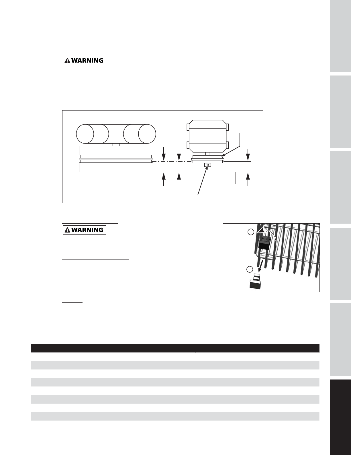
Belts
Lock out and tag the power then release all pressure from the tank to prevent unexpected
movement of the unit.
Check belt tension every 3 months. Adjust belt tension to allow 3/8 inch to 1/2 inch deflection with normal
thumb pressure. Also, align belts using a straight edge against the face of the flywheel and touching the
rim on both sides of the face. The belts should be parallel to this straight edge (see Figure 11). Dimension A
should be the same as B and C to ensure proper alignment of the belts.
Slots in the bed-plate allow for sliding the motor back and forth to adjust belt tension.
Motor
AB
Air Compressor
GETTING STARTED
SPECIFICATIONS
SAFETY /
Motor
Drive
Pulley
Flywheel
Straight Edge
Setscrew
Figure 11 - Top View
Removing Belt Guard
When removing belt guard front to
inspect or replace belts, inspect plastic retaining
clips and replace if damaged or if clip can be removed without a tool.
Removing Retaining Clips
1. Using crescent wrench on pliers, rotate clip 90°.
2. Pull clip out and away from beltguard.
3. Reverse process to reinstall after inspecting the clip.
Storage
If compressor is to be stored for a short period of time, make sure
that it is stored in a normal position and in a cool protected area.
Figure 12
INSTALLATION
ASSEMBLY /
C
1
2
TROUBLESHOOTINGOPERATION
Maintenance Schedule
OPERATION DAILY MONTHLY 3 MONTHS
Check Safety Valve
Drain Tank (see Figure 8)
Check Oil Level
Clean or Change Air Filter
Check Intercooler
Clean Unit Components
Check Belt Tightness
Change Oil (see Figure 6)
15
●
●
●
●
●
●
●
●
MAINTENANCE /
REPAIR
Page 18
SAFETY /
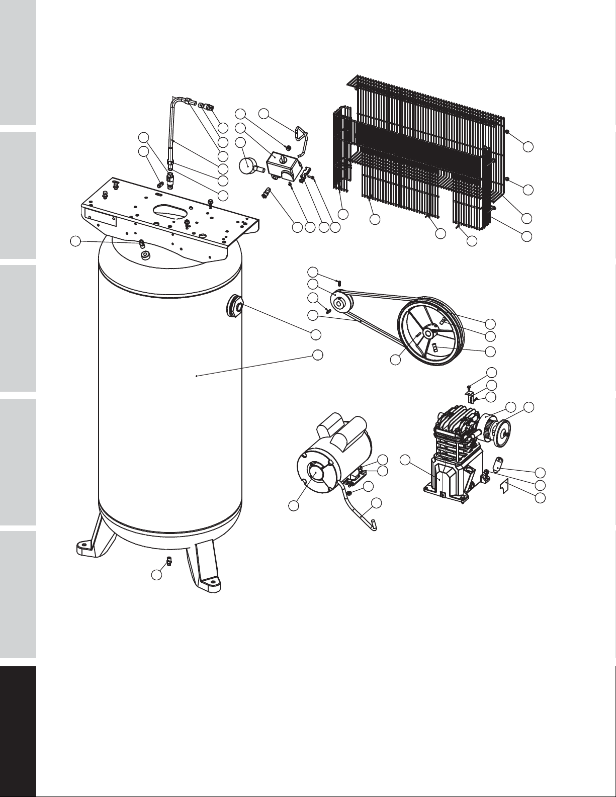
REPAIR PARTS ILLUSTRATION FOR VT6195 AND VT6395
16
GETTING STARTED
SPECIFICATIONS
14
15
13
20
21
17
22
17
24
29
32
19
9
9
33
25 26
27
18
12
10
11
33
33
33
8
7
ASSEMBLY /
INSTALLATION
28
35
36
2
31
1
3
1
4
5
34
1
1
1
23
30
33
1
1
1
6
1
MAINTENANCE /
TROUBLESHOOTING OPERATION
For Repair Parts, visit www.campbellhausfeld.com
24 hours a day – 365 days a year
Please provide following information:
- Model number
- Serial number (if any)
- Part description and number as shown in parts list
REPAIR
16
Page 19

GETTING STARTED
REPAIR PARTS LIST FOR VT6195 AND VT6395
Ref.
No. Description Part Number: Qty.
1 3HP VT PUMP ASSEMBLY VT4723 1
2 3.2HP 240V ELECTRIC MOTOR MC019700SJ 1
3 HEX HEAD SCREW, 5/16"-18 X 3/4" - 4
4 WASHER, 5/16" -4
5 SPINLOCK NUT, 5/16"-18 - 4
6 SELF TAPPING SCREW, 5/16"-12 - 4
7 WIRE BELT GUARD BACK BG218700AV 1
8 WIRE BELT GUARD FRONT BG218800AV 1
9 HEX FLANGE NUT 10-24 - 4
10 PULLEY 3.25" X 5/8" BORE PU012700AV 1
11 KEY, 3/16" X 1" KE000900AV 1
12 SET SCREW, 1/4"-20 X 1/2" - 1
13 PIPE NIPPLE, 1/4" NPT X 1.5" - 1
14 CHECK VALVE CV221502AV 1
15 QUICK CONNECT TUBE FITTING, 1/4" TUBE X 1/8" NPT ST081301AV 1
16 PLUG, 1/4" NPT -1
17 COMPRESSION NUT, 1/2" ST033001AV 2
18 ASME SAFETY VALVE, 150PSI V-215105AV 1
19 GAUGE, 300PSI GA031900AV 1
20 COMPRESSION FITTING, 1/2" NPT X 1/2" TUBE - 1
21 FERRULE, 1/2" -1
22 EXHAUST TUBE VT043300AP 1
23 TAPPING SCREW, 10-3/8" - 1
24 MOLDED FERRULE, 1/2" - 1
25 PRESSURE SWITCH WIRE CLAMP CW209700AV 1
26 CLAMP SCREW ST209800AV 1
27 HEX HEAD SELF TAPPING SCREW, 8 - 3/8" - 2
28 BELT, AX48 -1
29 PTFE TUBE, 1/4" X 14" - 1
30 BELT GUARD BRACKET BG220400AV 1
31 DRAINCOCK D-1403 1
32 PRESSURE SWITCH CW209300AV 1
33 TAPPING SCREW, 5-5/8" - 5
34 MOTOR POWER CORD, 16" EC012800AV 1
35 PLASTIC PLUG 3/4" NPT - 1
36 60 GALLON ASME TANK AR236500CG 1
SPECIFICATIONS
INSTALLATION
SAFETY /
ASSEMBLY /
17
TROUBLESHOOTINGOPERATION
MAINTENANCE /
REPAIR
Page 20
SAFETY /
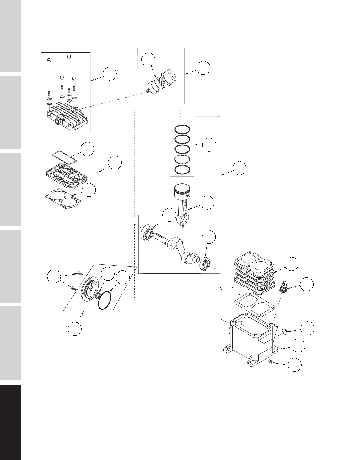
REPAIR PARTS ILLUSTRATION FOR VT4923
GETTING STARTED
SPECIFICATIONS
16
20
17
ASSEMBLY /
INSTALLATION
13
15
5
11
14
10
8
6
7
8
2
9
4
3
MAINTENANCE /
12
TROUBLESHOOTING OPERATION
For Repair Parts, visit www.campbellhausfeld.com
24 hours a day – 365 days a year
Please provide following information:
- Model number
- Serial number (if any)
- Part description and number as shown in parts list
REPAIR
18
19
1
18
Page 21

REPAIR PARTS LIST FOR VT4923
Ref.
No. Description Part Number: Qty.
1 CRANKCASE -- 1
2 CRANKCASE GASKET
3 BREATHER VH901100AV 1
4 CYLINDER -- 1
5 CYLINDER GASKET
6 CONNECTING ROD AND PISTON ASSEMBLY -- 2
7 PISTON RING SET -- 2
8 BALL BEARING -- 2
9 CRANKSHAFT, BEARINGS, RODS, PISTON ASSEMBLY -- 1
10 O-RING
11 OIL SEAL -- 1
12 BEARING CAP ASSEMBLY -- 1
13 M6 X 10 MM HEX CAP SCREW
14 VALVE PLATE ASSEMBLY VT491100AV 1
15 VALVE PLATE MOLDED SEAL
16 CYLINDER HEAD AND FASTENERS -- 1
17 AIR FILTER ASSEMBLY VH901700AV 1
18 1/8 IN.-27 OIL DRAIN PLUG -- 1
19 SIGHT GLASS ST191700AV 1
20 AIR FILTER ELEMENT VH901800AV 1
REPAIR PART KITS
●
-- NOT AVAILABLE
✝
GASKET KIT VT490900AV
AVAILABLE AT LOCAL HARDWARE STORE
●
●
●
✝
●
GETTING STARTED
1
1
SPECIFICATIONS
SAFETY /
1
4
1
INSTALLATION
ASSEMBLY /
19
TROUBLESHOOTINGOPERATION
MAINTENANCE /
REPAIR
Page 22

Reminder: Keep your dated proof of purchase for warranty purposes! Attach it to this manual or file it for safekeeping.
LIMITED WARRANTY
1. DURATION: The compressor pump and air receiver is warranted for three years from the date of purchase by the original
purchaser. The balance of the compressor package is warranted for one year from the date of purchase by the original
purchaser.
2. WHO GIVES THIS WARRANTY (WARRANTOR): Campbell Hausfeld a Marmon/Berkshire Hathaway Company, 100 Production
Drive, Harrison, Ohio, 45030. Visit www.campbellhausfeld.com
3. WHO RECEIVES THIS WARRANTY (PURCHASER): The original purchaser (other than for purposes of resale) of the Campbell
Hausfeld air compressor.
4. WHAT PRODUCTS ARE COVERED BY THIS WARRANTY: Campbell Hausfeld VT6195 & VT6395 air compressors.
5. WHAT IS COVERED UNDER THIS WARRANTY: Parts and Labor to remedy defects in material and/or workmanship with the
exceptions noted below.
6. WHAT IS NOT COVERED UNDER THIS WARRANTY:
A. Implied warranties, including those of merchantability and FITNESS FOR A PARTICULAR PURPOSE ARE LIMITED FROM
THE DATE OF ORIGINAL PURCHASE AS STATED IN THE DURATION. Some States do not allow limitations on how long an
implied warranty lasts, so the above limitations may not apply to you.
B. ANY INCIDENTAL, INDIRECT, OR CONSEQUENTIAL LOSS, DAMAGE, OR EXPENSE THAT MAY RESULT FROM ANY DEFECT,
FAILURE, OR MALFUNCTION OF THE CAMPBELL HAUSFELD PRODUCT. Some States do not allow the exclusion or
limitations of incidental or consequential damages, so the above limitation or exclusion may not apply to you.
C. Any failure due to:
1. Accident or purchaser’s abuse
2. Improper installation
3. Equipment that has not been operated or maintained in accordance with Campbell Hausfeld’s instructions as
detailed in the operating manual provided with the compressor.
4. Equipment that has been repaired or modified without authorization from Campbell Hausfeld.
D. Pre-delivery service, i.e. assembly, oil or lubricants, and adjustment.
E. The effects of normal wear and tear.
F. Gasoline engines and components are expressly excluded from coverage under this limited warranty. The Purchaser must
comply with the warranty given by the engine manufacturer which is supplied with the product.
G. Equipment that has been damaged in transit.
7. RESPONSIBILITIES OF WARRANTOR UNDER THIS WARRANTY: Repair or replace, at Warrantor’s option, compressor or
component which is defective, has malfunctioned and/or failed to conform within duration of the warranty period.
Warranted repairs will be made at the Purchaser’s location.
8. RESPONSIBILITIES OF PURCHASER UNDER THIS WARRANTY:
A. Provide dated proof of purchase and maintenance records.
B. Use reasonable care in the operation and maintenance of the products as described in the owner’s manual(s).
C. Repairs requiring overtime, weekend rates, or anything beyond the standard manufacturer warranty repair labor
reimbursement rate.
D. Time required for any security checks, safety training, or similar for service personnel to gain access to facility.
E. Location of unit must have adequate clearance for service personnel to perform repairs and easily accessible.
9. WHEN WARRANTOR WILL PERFORM REPAIR OR REPLACEMENT UNDER THIS WARRANTY: Repair or replacement will be
scheduled and serviced according to the normal work flow at the servicing location, and depending on the availability of
replacement parts.
This Limited Warranty applies in the U.S., Canada and Mexico only and gives you specific legal rights. You may also have other
rights which vary from State to State or country to country.
20
Page 23

Compresseurs d’air fi xes
Instructions d’Utilisation et Manual de Pièces
© 2016 Campbell Hausfeld
A Marmon/Berkshire Hathaway Company
Modèles: VT6195 et VT6395
FR
IN571500AV 6/16
Page 24

Lire et conserver ces instructions. Il faut les lire attentivement avant de
commencer à assembler, installer, faire fonctionner ou entretenir l’appareil décrit.
Pour se protéger et protéger autrui, observer toutes les informations sur la
sécurité. Négliger d’appliquer ces instructions peut causer
des blessures et/ou des dommages matériels! Conserver ces instructions pour
consultation ultérieure.
RAPPEL: Conservez votre preuve d’achat datée aux fi ns de garantie! Attachez-le à
ce manuel ou classez-le pour le garder en sécurité.
Pour de l’information sur les pièces,
produits et services veuillez visiter
N° de modèle : _____________________
N° de série : _______________________
Date d’achat : _____________________
ENREGISTREZ VOTRE PRODUIT EN LIGNE MAINTENANT ! www.campbellhausfeld.com
LIRE ET SUIVRE TOUTES LES INSTRUCTIONS • CONSERVER CES INSTRUCTIONS • NE PAS JETER
www.campbellhausfeld.com
Campbell Hausfeld
100 Production Drive
Harrison, Ohio 45030
Page 25

AVANT DE COMMENCER
Introduction
Les unités de compresseur d’air ont été conçues pour fournir de l’air comprimé aux outils électriques
pneumatiques, faire fonctionner les pistolets de pulvérisation et approvisionner en air les soupapes et
actionneurs pneumatiques. Les pompes alimentées par ces unités comportent des roulements lubrifiés à
l’huile. Un faible contenu en huile est présent dans le flux d’air comprimé. Les applications nécessitant de
l’air sans vapeurs d’huile devraient disposer de filtres adéquats déjà installés. Les unités de compresseur
d’air doivent être installées selon les instructions fournies sur un plancher solide. Toute autre utilisation de
ces unités annulera la garantie et le fabricant ne sera pas tenu responsable des problèmes ou dommages
résultant de cette mauvaise utilisation.
RÉFÉRENCE RAPIDE
Huile recommandée (2 Options)
Huile de compresseur non détergente SAE 30 ISO100 à viscosité unique. Numéro de pièce
ST125303AV (0,47 L) ou ST126701AV (3,79 L).
Huile synthétique 10W30 telle que Mobil 1® ou CE0032 (0,95 L).
Capacité D’Huile
Environ 0,25 L.
DE L’APPAREIL
DÉMARRAGE
SÉCURITÉ / CARACTÉRISTIQUES
ASSEMBLAGE /
INSTALLATION
DÉBALLAGE
Ne pas soulever ni déplacer le modèle sans équipement convenable et s’assurer
les refroidisseurs. Ne pas utiliser le modèle pour soulever d’autre équipement qui est attaché au compresseur.
Dès que l’appareil est déballé, l’inspecter attentivement pour tout signe de dommages en transit. Vérifier
s’il y a des pièces desserrées, manquantes ou endommagées. Vérifier pour s’assurer que tous les accessoires
fournis sont inclus avec l’appareil. Pour toutes questions, pièces endommagées ou manquantes, veuillez
visiter www.campbellhausfeld.com pour l’assistance à la clientèle.
Ne pas utiliser l’appareil s’il est endommagé pendant le transport, la manutention
des dommages à la propriété.
Autres articles non inclus
• Huile
que le modèle soit bien fixé à l’appareil de levage. Ne pas soulever le modèle avec les tuyaux ou
UTILISATION
ou l’utilisation. Des dommages peuvent entraîner un éclatement et provoquer des blessures ou
DÉPANNAGE
Fr1
ENTRETIEN /
RÉPARATION
Page 26

INSTRUCTIONS GÉNÉRALES DE SÉCURITÉ
Directives de Sécurité
Ce guide contient de l’information très importante que vous devez savoir et comprendre. Cette information
DÉMARRAGE
DE L’APPAREIL
SÉCURITÉ / CARACTÉRISTIQUES
est fournie à des fins de SÉCURITÉ et dans le but d’ÉVITER DES PROBLÈMES AVEC L’ÉQUIPEMENT. Pour
faciliter la reconnaissance de cette information, prenez compte des symboles suivants.
Danger indique une situation hasardeuse imminente qui RÉSULTERA en perte de
Avertissement indique une situation hasardeuse potentielle qui PEUT résulter en
Attention indique une situation hasardeuse potentielle qui PEUT résulter en
Avis indique de l’information importante pour éviter le dommage de
REMARQUE : Remarque indique : des renseignements additionnels concernant le produit ou son utilisation.
Symboles De Sécurité
Les symboles de sécurité suivants apparaissent dans l’ensemble de ce manuel pour vous aviser des dangers
et précautions importants de sécurité.
vie ou blessures graves.
perte de vie ou blessures graves.
blessures.
l’équipement.
MANUAL
INSTALLATION
ASSEMBLAGE /
UTILISATION
DÉPANNAGE
Porter une
protection oculaire
et un masque
Risques de
fumées
Lire le manuel
d’abord
Risque de
pression
Risque
d’incendie
Risque de
choc
Risque de
pièces mobiles
Risque
de pièces
chaudes
Risque
d’explosion
Proposition 65 de Californie
Ce produit, utilisé pour la soudure, produit des vapeurs ou gaz qui contiennent des
autre tort aux organes de la reproduction), et en quelques circonstances, le cancer. (le code `California Health & Safety
Code Section 25249.5 et seq’.).
Ce produit et son cordon contient du plomb, un produit chimique qui de l’avis de
pour la reproduction. Se laver les mains après toute manipulation.
produits chimiques prouvés par I’État de Californie de provoquer des dé fauts de naissance (ou
l’État de Californie peut causer le cancer et des anomalies congénitales ou d’autres problèmes
Consignes importantes de sécurité
Veuillez lire et conserver ces instructions. Lisez attentivement avant d’essayer d’assembler, d’installer, de faire
fonctionner ou de réparer le produit décrit. Protégez-vous et les autres en considérant toutes les informations de
sécurité. Le non-respect des instructions pourrait entraîner des blessures corporelles et/ou des dommages matériels!
Conservez toutes les instructions pour vous y référer ultérieurement.
Ce manuel contient des informations importantes sur la sécurité opérationnel et entretien. Si vous avez des
questions, veuillez visiter www.campbellhausfeld.com pour l’assistance à la clientèle.
Puisque le compresseur d’air et les autres composants (article pompe, pistolet de pulvérisation, filtres,
lubrifiants, tuyaux, etc.) utilisés font partie d’un système de pompage à haute pression, les précautions de
sécurité suivantes doivent être prises en considération à tout moment :
ENTRETIEN /
RÉPARATION
Fr2
Page 27

Consignes importantes de sécurité (Suite)
AVERTISSEMENT D’AIR RESPIRABLE
Ce compresseur/pompe n’est pas équipé pour et ne devrait pas être utilisé “comme soi” pour fournir
de l’air respirable. Pour les applications d’air pour la consommation humaine, il est nécessaire
d’équiper le compresseur d’air/pompe avec de l’équipement de sécurité en canalisation et d’alarme.
Cet équipement additionnel est nécessaire pour filtrer et purifier l’air afin d’atteindre les spécifications
minimales pour la respiration Grade D décrite dans le Compressed Gas Association Commodity
Specification G 7.1, OSHA 29 CFR 1910. 134, and/or Canadian Standards Associations (CSA).
DÉNÉGATION DES GARANTIES
Si le compresseur est utilisé pour les applications d’air respirable et l’équipement de sécurité en
canalisation et d’alarme n’est pas utilisé simultanément, les garanties en existance seront annulées, et
le fabricant dénie toute responsabilité pour n’importe quelle perte, blessure ou dommage.
Généralités sur la Sécurité
• Lire attentivement tous manuels compris avec ce produit. Bien se familiariser avec les commandes et
MANUAL
l’utilisation correcte de l’équipement.
• Suivre tous les codes d’électricité et de sécurité locaux ainsi que: National Electrical Codes (NEC) et
Occupational Safety and Health Act (OSHA) des É.-U.
• Seules les personnes bien familiarisées avec ces règles d’utilisation doivent être autorisées à se servir du
compresseur.
• Garder les visiteurs à l’écart de/et NE JAMAIS permettre les enfants dans l’endroit de travail.
• Utiliser des lunettes de sécurité et la protection auditive pendant l’utilisation du modèle.
• Ne pas se tenir debout sur/ou utiliser le modèle comme une prise.
• Inspecter le système d’air comprimé et pièces détachées électriques pour toute indication de dommage,
détérioration, faiblesse ou fuites avant chaque utilisation. Réparer ou remplacer toutes pièces
défectueuses avant l’utilisation.
• Inspecter le degré de serrage de toutes attaches par intervalles régulières.
Les moteurs, l’équipement et les commandes électriques peuvent causer des arcs électriques
qui peuvent allumer un gaz ou une vapeur inflammable. Ne jamais utiliser ou réparer le
modèle près d’un gaz ou d’une vapeur inflammable. Ne jamais entreposer les liquides ou gaz inflammables près du
compresseur.
Ne jamais utiliser un compresseur sans carter de courroie. Ce modèle peut se démarrer sans
avis. Le contact avec les pièces mobiles peut causer des blessures personnelles ou dégâts
matériels.
• Ne pas porter les vêtements flottants ni la bijouterie qui peuvent se prendre dans les pièces mobiles du
modèle.
Les pièces du compresseur peuvent être chaudes même si le modèle n’est pas en
marche.
• Garder les doigts à l’écart d’un compresseur qui est en marche; les pièces mobiles et chaudes peuvent
causer des blessures et/ou brûlures.
• Si le compresseur vibre anormalement, ARRÊTER le moteur et l’inspecter immédiatement. La vibration
est généralement une indication d’un problème.
• Pour réduire le risque d’incendie, garder l’extérieur du moteur libre d’huile, de solvant ou de graisse
excessive.
Une soupape de sécurité ASME avec une configuration ne dépassant pas le maximum autorisé.
Un robinet de sûreté et de décharge de code ASME comportant un réglage ne dépassant pas
la pression maximale de marche permise (PMMP) du réservoir DOIT être installé dans le réservoir de ce compresseur.
La soupape de sécurité ASME doit être d’une classification de débit et de pression suffisants à protéger les composants
sous pression contre l’éclatement. Le débit peut être trouvé dans le manuel des pièces.
DE L’APPAREIL
DÉMARRAGE
SÉCURITÉ / CARACTÉRISTIQUES
ASSEMBLAGE /
INSTALLATION
UTILISATION
DÉPANNAGE
ENTRETIEN /
RÉPARATION
Fr3
Page 28

Consignes importantes de sécurité (Suite)
La pression de fonctionnement maximale est de 931 kPa pour les compresseurs
DÉMARRAGE
DE L’APPAREIL
une valeur supérieure à 931 kPa (monophasé).
• Ne jamais essayer d’ajuster la soupape de sûreté ASME. Garder la soupape de sûreté libre de peinture et
Ne jamais utiliser les tuyaux plastiques (CPV) pour l’air comprimé. Ceci peut
Ne jamais essayer de réparer ni de modifier un réservoir! Le soudage, le perçage ou autre
d’explosion. Toujours remplacer un réservoir usé, fendu ou endommagé.
• L’accumulation d’humidité cause la rouille qui peut affaiblir le réservoir. Purger le réservoir
SÉCURITÉ / CARACTÉRISTIQUES
• L’air mouvante peut agiter la poussière et le débris qui peut être dangereux. Lâcher l’air lentement en
Précautions de Pulvérisation
Ne pas pulvériser les matériaux inflammables dans un endroit de flamme ouverte
INSTALLATION
ASSEMBLAGE /
• Ne pas fumer pendant la pulvérisation de la peinture, d’insecticides ou autres matières inflammables.
• Utiliser un masque/respirateur pendant la pulvérisation et pulvériser dans un endroit bien aéré pour
• Ne pas diriger la peinture ou autre matériel pulvérisé vers le compresseur. Situer le compresseur aussi
• Suivre les instructions du fabricant pendant la pulvérisation ou le nettoyage avec des solvants ou
Voir les spécifications du compresseur pour une pression de fonctionnement maximale. Ne pas faire
fonctionner avec un manostat ou soupapes pilotes réglés au delà de la pression de fonctionnement
maximum.
monophasés. Ne pas faire fonctionner avec un manostat ou des vannes pilotes configurés sur
autres accumulations.
causer des blessures graves ou la mort.
modifications peuvent affaiblir le réservoir et peut résulter en dommage de rupture ou
Purger le liquide du réservoir quotidiennement.
quotidiennement et l’inspecter périodiquement pour la rouille et la corrosion ou autre dommage.
purgeant l’humidité ou pendant la dépressurisation du système de compresseur.
ni près d’une source d’ignition y compris le compresseur.
éviter le risque de blessures et d’incendie.
loin que possible de l’endroit de pulvérisation pour réduire l’accumulation de surpulvérisation sur le
compresseur.
produits chimiques toxiques.
UTILISATION
DÉPANNAGE
Conserver ces instructions
Ne les jetez pas
Les symboles DANGER, AVERTISSEMENT, ATTENTION ET AVIS ainsi que les instructions de ce manuel
ne peuvent pas couvrir toutes les conditions et situations qui pourraient se produire. L’opérateur doit
comprendre que les précautions sont des facteurs qui ne peuvent pas être inclus dans ce produit,
maisdoivent être fournis par l’opérateur.
ENTRETIEN /
RÉPARATION
Fr4
Page 29

Apprendre à Connaître Votre Compresseur
Moteur
Manostat
Tuyau d'échappement
Pompe de
compresseur
Filtre à air
Tube du dispositif de
délestage
DE L’APPAREIL
DÉMARRAGE
SÉCURITÉ / CARACTÉRISTIQUES
ASSEMBLAGE /
INSTALLATION
Manomètre de
réservoir
Soupape de sécurité
UTILISATION
DÉPANNAGE
Figure 1 – Identification de l’unité verticale
Vidange du réservoir
manuel
Fr5
ENTRETIEN /
RÉPARATION
Page 30

CARACTÉRISTIQUES TECHNIQUES
Moteur HP 3.7
DÉMARRAGE
DE L’APPAREIL
SÉCURITÉ / CARACTÉRISTIQUES
Alimentation 208-230V
Étape 1
Déplacement CFM 345,5 l/min
Débit d’air CFM à 621 kPa 288,8 l/min
Débit d’air CFM à 965 kPa 277,5 l/min
kPa max. 931
Pompe RPM 1020
Capacité du réservoir 227,10 L
Poids de l’unité 115.67 kg
Ampérage 14,5
Cycle d’exploitation max. 75%
Sortie du réservoir 3/4 po NPT
Réservoir MAWP 1207 kPa
DIMENSIONS
VT6195 et VT6395
INSTALLATION
ASSEMBLAGE /
Longueur 23 po
Largeur 25 po
Hauteur 66 po
MODÈLE VISSÉ
UTILISATION
60,96 cm
DÉPANNAGE
26,39 cm 26,39 cm
120.00
o
VT6195 et VT6395
15,24 cm
30,48 cm
ENTRETIEN /
RÉPARATION
Fr6
Page 31

INSTRUCTIONS D’INSTALLATION
Débrancher, étiquetter et vérouiller la source de puissance électrique et dissiper
toute la pression du système avant d’essayer d’installer, réparer, déplacer ou de procéder à
l’entretien du modèle.
Ne pas soulever ni déplacer le modèle sans équipement convenable et s’assurer q
ue le modèle soit bien fixé à l’appareil de levage. Ne pas soulever le modèle avec les tuyaux ou les
refroidisseurs. Ne pas utiliser le modèle pour soulever d’autre équipement qui est attaché au compresseur.
Ne jamais utiliser les palettes d’expédition
pour monter le compresseur.
Choisir l’emplacement
Installer et utiliser le modèle au moins de 46 cm (18 po) d’une
obstruction et dans un endroit propre et bien ventilé. La
température de l’air dans l’endroit ne devrait pas dépasser 38,08°
C. Ceci assure un débit d’air sans obstruction pour refroidir le
compresseur et permet de l’espace pour l’entretien.
Ne pas situer la prise d’air du compresseur
près de vapeurs, pulvérisation de peinture,
endroits de décapage au sable ou n’importe quelle autre source de
contamination.
REMARQUE: Si le compresseur est utilisé dans un endroit chaud
et humide, il est nécessaire de fournir le compresseur avec de l’air
extérieur propre et sec. Cet air devrait être canalisé d’une source
externe.
45,72 cm
45,72 cm
45,72 cm
DE L’APPAREIL
DÉMARRAGE
SÉCURITÉ / CARACTÉRISTIQUES
ASSEMBLAGE /
INSTALLATION
Montage du réservoir
Le résevoir devrait être boulonné dans un plancher en béton
plat et égal ou sur une fondation en béton séparée. Utiliser des
tampons isolateurs entre la jambe du réservoir et le plancher.
Figure 2 - Emplacement
Les blocs d’isolation du modèle MP345700AJ sont recommandés
pour l’installation.
Ne pas trop serrer les boulons en utilisant les tampons isolateurs
afin de permettre que les tampons absorbent les vibrations. Un
tuyau ou raccord flexible doit être installé entre le réservoir et la
tuyauterie de service.
Le fait de ne pas installer le réservoir
soudés et la possibilité d’éclatement.
correctement peut causer des fentes aux joints
Tuyauterie
Ne Jamais utiliser les tuyaux en plastique
blessures graves ou perte de vie.
(CPV) pour l’air comprimé. Ceci peut résulter en
N’importe quel tube, tuyau ou tuyau flexible branché au modèle doit pouvoir résister la température qui est
produit et doit conserver la pression. Tous les composants sous pression du système d’air doivent avoir une
valeur nominale de pression de 1 379 kPa ou plus. La sélection ou l’installation incorrecte de n’importe quel
tube, tuyau ou tuyau flexible peut résulter en éclatement et en blessures. Brancher le système de tuyauterie
au réservoir en utilisant un raccord de même taille que celui de l’orifice de décharge.
Taille De Tuyau Minimum Pour Canalisation D’air Comprimé
Longueur Du Système
l/min
7,62 m 15,24 m 30,48 m 76,2 m
283.2 12,7 mm 12,7 mm 19,1 mm 19,1 mm
566.3 19,1 mm 19,1 mm 19,1 mm 2,54 cm
1132.7 19,1 mm 2,54 cm 2,54 cm 2,54 cm
1699.0 19,1 mm 2,54 cm 2,54 cm 2,54 cm
2831.7 2,54 cm 2,54 cm 2,54 cm 3,18 cm
Figure 3 - Coussinet isolant
UTILISATION
DÉPANNAGE
ENTRETIEN /
RÉPARATION
Fr7
Page 32
INSTRUCTIONS D’INSTALLATION (SUITE)
Installation D’une Soupape D’arrét
DÉMARRAGE
DE L’APPAREIL
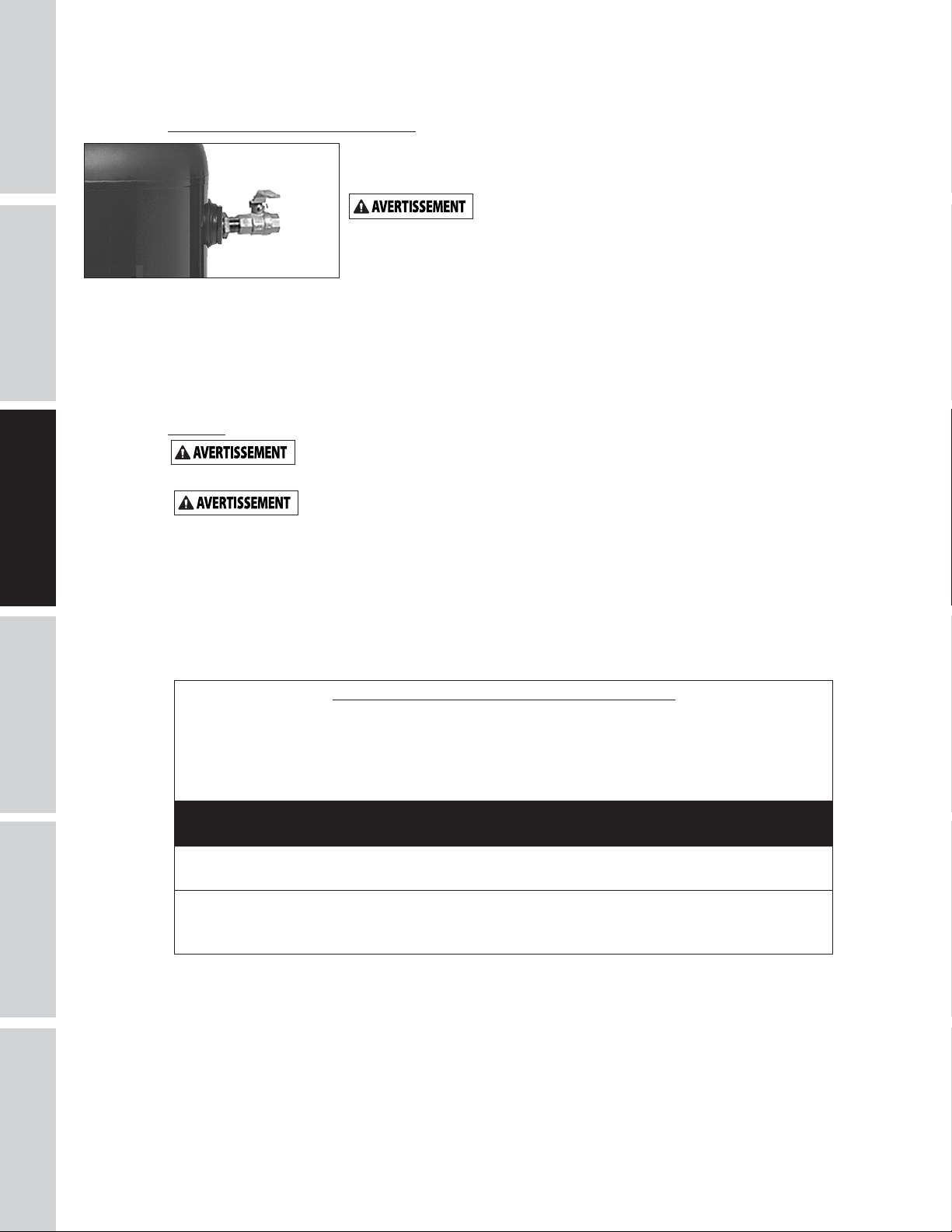
Figure 4
- Soupape d’arrêt
Appliquer la pression d’air à la tuyauterie et assurer que toutes les jointures sont sans fuites AVANT de
couvrir les lignes souterraines. Rechercher et réparer toutes les fuites dans les tuyaux et raccords avant
SÉCURITÉ / CARACTÉRISTIQUES
INSTALLATION
ASSEMBLAGE /
d’utiliser le compresseur.
Câblage
Tout le câblage et les connexions électriques doivent être exécutés par un
aux codes locaux et nationaux.
L’installation de fils doit conformer aux National Electrical Code et aux codes et règlements locaux
concernant les appareils électriques et l’installation de fils. Consulter avec et observer ceux-ci. Utiliser la
taille correcte de fil et assurer que:
1. L’ampérage du service soit suffisant.
2. La ligne d’alimentation corresponde au moteur (tension, cycles et phase).
3. La taille du fil de ligne est correcte et qu’il n’y a pas d’autre équipement qui fonctionne sur la même
Une soupape d’arrêt devrait être installée sur l’orifice de décharge du réservoir
pour régler le débit d’air du réservoir. La soupape devrait être située entre le
réservoir et le système de tuyauterie.
Ne jamais installer une soupape d’arrêt entre
blessures personnelles et/ou dommage à l’équipement. Ne jamais utiliser un appareil de
réduction dans le tuyau flexible de refoulement.
la pompe du compresseur et le réservoir. Ceci peut résulter en
Pour un système d’installation permanent pour la distribution d’air comprimé,
calculer la longueur du système et choisir la taille du tuyau selon le tableau.
Enterrer les lignes souterraines sous le niveau de gélée et éviter les poches où la
condensation pourrait s’accumuler et geler.
électricien qualifié au courant des contrôles à moteurs industriels. L’installation doit conformer
Un câblage inadéquat mènera à la surchauffe, les court-circuits et les dommages d’incendie.
ligne. Le tableau indique la taille minimum de fil pour les installations de compresseurs.
UTILISATION
DÉPANNAGE
Taille de fil minimum utiliser le fil en cuivre 75°C
S’assurer que la tension est correcte avec le câblage du moteur.
REMARQUE: Si l’on utilise une monophase de 208 volts, s’assurer que la plaque
signalétique du moteur indique une valeur nominale de 208 volts en monophase. Les
moteurs monophases de 230 volts ne fonctionnent pas à 208 volts à moins que ce ne soit
une valeur de 208 volts.
MONOPHASÉ
HP AMPS 230V
1-4 HP jusqu’à 22,0 10 AWG
5.0 8 AWG
Les tailles de fils recommandées peuvent être plus larges que la configuration minimum des ordonnances
locales. Si c’est le cas, utiliser le fil d’une taille plus large pour prévenir toute chute de tension excessive sur la
ligne. Le coût supplémentaire du fil est très petit comparativement au coût de réparation ou de remplacement
d’un moteur « épuisé » électriquement par l’utilisation de fils d’alimentation trop petits.
ENTRETIEN /
RÉPARATION
Fr8
Page 33

INSTRUCTIONS D’INSTALLATION (SUITE)
Mise à la terre
Les composantes électriques qui ne sont pas correctement mise à la terre tiennent le risque
de secousse électrique. S’assurer que toutes les pièces soient mise à la terre correctement pour
éviter les blessures personnelles ou la perte de vie.
Ce produit doit être mise à la terre pour diminuer le risque de secousse électrique en fournissant un fil
d’échappement s’il y arrive un court-circuit. Ce produit doit étre installé avec et utilisé avec un cordon
d’alimentation qui a un fil de terre.
Disjoncteurs et Fusibles
Tout le système électrique doit être vérifié par un électricien agréé. Des fusibles et disjoncteurs à
retardement sont nécessaires pour ce compresseur. Un fusible grillé ou un disjoncteur déclenché peut
indiquer un court-circuit direct à la terre, un tirage élevé de courant, un mauvais câblage, un fusible ou un
disjoncteur de mauvaise taille et/ou type. Ceci doit être évalué par un électricien agréé.
Mise à la terre
DE L’APPAREIL
DÉMARRAGE
SÉCURITÉ / CARACTÉRISTIQUES
ASSEMBLAGE /
INSTALLATION
L1
L2
Moteur
UTILISATION
DÉPANNAGE
Figure 5 - Schéma de câblage
Fr9
ENTRETIEN /
RÉPARATION
Page 34

INSTRUCTIONS D’INSTALLATION
Installer le filtre d’entrée d’air
Vissez le filtre d’entrée d’air fourni dans le port d’entrée
DÉMARRAGE
de la pompe en fonte, tel qu’indiqué à la Figure 6.
DE L’APPAREIL
Graissage
CE MODÈLE NE CONTIENT PAS
Remplir au centre de la jauge visuelle (voir la figure 6).
L’utilisation d’un autre type d’huile
et endommager les soupapes.
Recommended Oil (2 Options)
Huile de compresseur non détergente SAE 30 ISO100 à
SÉCURITÉ / CARACTÉRISTIQUES
INSTALLATION
ASSEMBLAGE /
viscosité unique. Numéro de pièce ST125303AV (0,47 L)
ou ST126701AV (3,79 L).
Huile synthétique 10W30 telle que Mobil 1® ou CE0032 (0,95 L).
Capacité D’Huile
Environ 0,25 L.
Remplir la pompe d’huile au centre de la jauge visuelle en
utilisant l’ouverture de remplissage d’huile (voir la figure
6). NE PAS remplir la pompe jusqu’à l’ouverture du bouchon
de reniflard, car ceci pourrait mener à une fuite d’huile et une
pulvérisation vers l’extérieur durant l’utilisation.
REMARQUE: Il pourrait y avoir des résidus d’huile dans
la pompe des tests en usine laissant une mince couche sur
la jauge visuelle, mais il n’y a pas assez d’huile pour faire
fonctionnerl’unité.
FONCTIONNEMENT
IMPORTANT: Vérifier la rotation du moteur avant
d’utiliser le compresseur.
Toutes les pompes de compresseur graissées débitent un
UTILISATION
peu d’humidité et d’huile avec l’air comprimé. Installer
l’équipement pour l’enlevage d’eau/huile et commandes
convenables à l’application.
Manque d’installer l’équipement
endommager les machines ou l’objet de travail.
Port
d'entrée
D’HUILE. Avant d’utiliser le compresseur.
pourrait raccourcir la durée de la pompe
Zone de
remplissage
de l'huile
Capuchon
de vidange
d’huile
Plein
Bas
Regard
Figure 6 - Graissage
pour ’élevage d’eau/huile peut
DÉPANNAGE
ENTRETIEN /
RÉPARATION
Carters
Le carter de courroie fournit doit
Toutes les pièces mobiles doivent être protégées. Tous
les couvercles électriques doivent être installés avant de
mettre en circuit.
être installé avant l’utilisaton du modèle.
Fr10
Page 35

FONCTIONNEMENT (SUITE)
Rodage Recommandé
Le compresseur devrait fonctionner en continu pendant une heure à moins de 621 kPa pour permettre aux
bagues de piston d’être dans la bonne position.
1. Ouvrir le robinet de purge et faire fonctionner le compresseur pour 60 minutes.
2. Mettre le compresseur hors circuit et fermer le robinet de purge. Le compresseur est maintenant prêt à
utiliser.
Si le compresseur fonctionne dans des conditions humides
pendant de courtes périodes, l’humidité se condensera
dans le carter et donnera à l’huile une apparence crémeuse.
L’huile contaminée par de l’eau condensée n’offrira pas la
lubrification nécessaire et devra être changée immédiatement.
L’utilisation d’huile contaminée endommagera les roulements,
les pistons, les cylindres et les joints et n’est pas couverte par
la garantie. Pour éviter la condensation de l’eau dans l’huile,
faites périodiquement fonctionner le compresseur avec une
pression au réservoir près de 827 kPA pour un compresseur à
deux phases ou 120 psi pour un compresseur à phase unique,
en ouvrant le robinet de vidange ou un robinet d’admission
d’air branché au réservoir ou à un tuyau. Faites fonctionner
la pompe pendant une heure à la fois, au moins une fois par
semaine ou plus fréquemment si la condensation se produit
encore.
IMPORTANT : Changez l’huile après les premières 50 heures d’utilisation ou toutes les 200 heures après.
Dispositif de
délestage
(derrière le manostat)
Soupape
de sécurité
Figure 7 - Pressure Switch
DE L’APPAREIL
DÉMARRAGE
SÉCURITÉ / CARACTÉRISTIQUES
ASSEMBLAGE /
INSTALLATION
Manostat Démarrage - Arrêt
REMARQUE: La pression de fonctionnement maximale est de 931 kPa pour les compresseurs monophasés.
Ne pas altérer les réglages de pression sur les pièces de commandes afin qu’ils dépassent cette limite.
Le compresseur démarre et s’arrête selon les configurations de pressostat préréglées de 724 kPa de
fermeture et de 931 kPa de coupure. Le manostat a un appareil de déchargement qui est une soupape qui
sert à ventiler l’air et permet le démarrage facile du modèle (Voir la Figure 7).
La soupape de décharge du pressostat devrait siffler pendant un certain temps lorsque le compresseur
s’éteint. Ceci dégage la hauteur de charge et le tube d’échappement de toute pression et permet au
compresseur de démarrer sans charge. Puisque les compresseurs ont un couple de démarrage élevé, il faut la
décharge pour un démarrage approprié du compresseur.
Le clapet de non-retour est un clapet d’une direction qui conserve l’air dans le réservoir lorsque l’appareil
est éteint. Le moyen le plus facile pour déterminer si le clapet de non-retour fonctionne correctement est
de s’assurer que la décharge de pressostat cesse de siffler après que le compresseur s’éteint. Ce sifflement
devrait durer quelques secondes, puis s’arrêter.
Reniflard du Carter
Un peu d’huile peut s’accumuler à l’ouverture du reniflard du carter pendant les conditions de
fonctionnement sévères ou pendant le premier démarrage. Ceci est normal et diminuera après le rodage et
une fois que les segments de piston seront ajustés.
Vidange du Reservoir
Le condensat doit être vidé du réservoir chaque jour.
Pour les modèles de série d’air d’atelier, utiliser un
drain de réservoir manuel (voir la figure 8).
UTILISATION
DÉPANNAGE
ENTRETIEN /
RÉPARATION
Fr11
Figure 8 - Drain de réservoir manuel
Page 36

GUIDE DE DÉPANNAGE
SYMPTÔME CAUSE(S) POSSIBLE(S) ACTION CORRECTIVE
Pression de décharge basse 1. Demande d’air dépasse la capacité de
DÉMARRAGE
DE L’APPAREIL
SÉCURITÉ / CARACTÉRISTIQUES
INSTALLATION
ASSEMBLAGE /
UTILISATION
DÉPANNAGE
Le filtre à air fond à cause du
surchauffage de la pompe
Bruit excessif (cognement) 1. Moteur ou poulie de compresseur
Large quantité d’huile dans l’air
de décharge
REMARQUE: Il y aura toujours
un peu d’huile dans le jet d’air
avec un compresseur graissé par
l’huile.
Eau dans l’air de débit/réservoir 1. Fonctionnement normal. La quantité
Le moteur ronronne et
fonctionne lentement ou pas
du tout
la pompe
2. Fuites d’air 2. Écouter pour des fuites d’air. Appliquer une solution
3. Arrivée d’air limitée 3. Nettoyer la cartouche filtrante.
4. Joints éclatés 4. Remplacer tous joints défectueux.
5. Fuites ou dommage aux soupapes 5. Enlever la culasse et inspecter pour des soupapes
1. Joint isolant entre le filtre et la culasse
manquant
2. Soupape cassée/joint éclaté 2. Remplacer les soupapes ou installer un nouveau joint
dégagé
2. Manque d’huile dans le carter 2. Vérifier le niveau d’huile; si bas, inspecter les paliers
3. Bielle usée 3. Remplacer la bielle. Entretenir le niveau d’huile et
4. Alésages d’axe de piston usés 4. Enlever le piston équipé du compresseur et l’inspecter
5. Piston frappe la plaque de soupape 5. Enlever la tête du compresseur et la plaque de
6. Clapet bruyant dans le système de
compresseur
1. Segments de piston usés 1. Remplacer les segments de piston. Entretenir le
2. Arrivée d’air du compresseur limité 2. Nettoyer le filtre. Vérifier le système d’arrivée pour
3. Huile excessive dans le compresseur 3. Vidanger jusqu’au niveau plein.
4. Viscosité d’huile incorrecte 4. Utiliser l’huile Mobil 1®10W-30
d’eau augmente avec le temps humide
1. Cordon prolongateur utilisé 1. N’utilisez pas un cordon prolongateur. Utilisez un
2. Fonctionnement défectueux du clapet
ou de la soupape de déchargement
3. Basse tension 3. Vérifier avec un voltmètre, inspecter le disjoncteur
4. Panne de manostat - contacts ne
ferment pas
1. Diminuer la demande d’air ou utiliser un compresseur
de plus haute capacité.
savonneuse à tous les raccords et branchements et
vérifier pour des bulles qui indiquent des fuites.
Serrer ou remplacer les raccords ou branchements qui
ont des fuites.
cassées, soupapes mal dressées, sièges de soupapes
endommagés, etc. Remplacer toutes les pièces
défectueuses et remonter.
Installer un nouveau joint
d’étanchéité de culasse chaque
fois que la culasse est enlevée
1. Installer un joint d’étanchéité.
d’étanchéité.
1. Poulies de moteur et de compresseur dégagés sont
causes communes de cognement. Serrer les boulons
de serrage et vis de pression de poulie.
pour du dommage. L’huile sale peut causer l’usure
excessif.
changer l’huile plus souvent.
pour l’usure excessif. Remplacer les axes de piston ou
pistons usés au besoin. Entretenir le niveau d’huile
correct et changer l’huile plus souvent.
soupape et inspecter pour de l’encrassement
charbonneux ou autre matières étranges sur la
partie supérieure du piston. Remplacer la culasse et
la plaque de soupape et utiliser un nouveau joint
d’étanchéité. Voir la section de Graissage pour l’huile
recommandée.
6. Remplacer.
Ne pas démonter le clapet si le
réservoir est pressurisé
niveau d’huile correct et changer l’huile plus souvent.
autres restrictions.
1. Purger le réservoir plus souvent, au moins
quotidiennement.
2. Ajouter un filtre pour diminuer la quantité d’eau
dans la canalisation d’air.
tuyau d’air plus long avec un diamètre plus large.
2 .Remplacer le clapet, la soupape de déchargement ou
le manostat.
Ne pas démonter le clapet
si le réservoir est pressurisé
de réenclenchement du moteur. Si le disjoncteur de
réenclenchement se déclenche à maintes reprises,
rechercher et corriger la cause. Voirl’article suivant.
4. Réparer ou remplacer le manostat.
ENTRETIEN /
RÉPARATION
Fr12
Page 37

GUIDE DE DÉPANNAGE (SUITE)
SYMPTÔME CAUSE(S) POSSIBLE(S) ACTION CORRECTIVE
Le mécanisme de
réenclenchement se déclenche
à maintes reprises ou les
fusibles sautent à maintes
reprises
Le réservoir ne conserve pas la
pression quand le compresseur
est hors circuit et la soupape
d’arrêt est fermée
Le manostat laisse souffler de
l’air continuellement à travers
de la soupape de déchargement
Le manostat ne relâche pas l’air
lorsque le modèle se coupe (off)
Vibration excessive 1. Attaches désserrés 1. Serrer.
1. Trop d’appareils sur le même circuit 1. Limiter l’usage du circuit au compresseur d’air
2. Taille de fusible ou de disjoncteur
incorrecte
3 .Fonctionnement défectueux du clapet 3. Remplacer le clapet.
4. Manostat réglé trop haut 4. Régler ou remplacer.
5. Fils désserrés 5. Inspecter tous les branchements électriques.
6. Fonctionnement défectueux du
moteur
1. Clapet usé 1. Remplacer le clapet.
2. Inspecter tous branchements et
raccordements pour des fuites
3. Inspecter le réservoir pour des fentes
ou des trous d’épingles
1. Fonctionnement défectueux du clapet 1. Remplacer le clapet si la soupape de déchargement a
1. Fonctionnement défectueux de la
soupape de déchargement sur le
manostat
2. Changement de la courroie exigé 2. Remplacer avec une courroie de taille correcte.
3. Redressage de la courroie 3. Aligner le volant et la poulie.
seulement.
2. Vérifier la classification des fusibles et des
disjoncteurs.
Ne pas démonter le clapet si le
6. Remplacer le moteur.
Ne pas démonter le clapet si le
2. Serrer.
3. Remplacer le réservoir. Ne jamais réparer un réservoir
endommagé.
une fuite d’air continue.
Ne pas démonter le clapet si le
1. Remplacer le manostat si la pression n’est pas dissipé
pendant une courte durée quand le modèle se
coupe.
Ne pas démonter le manostat si
réservoir est pressurisé
réservoir est pressurisé
réservoir est pressurisé
le réservoir est pressurisé
DE L’APPAREIL
DÉMARRAGE
SÉCURITÉ / CARACTÉRISTIQUES
ASSEMBLAGE /
INSTALLATION
UTILISATION
DÉPANNAGE
ENTRETIEN /
RÉPARATION
Fr13
Page 38

INSTRUCTIONS D’ENTRETIEN ET D’INSPECTION
Débrancher, étiquetter, verrouiller la source de puissance et ensuite dissiper toute
Vérifier le filtre à air et le niveau d’huile avant chaque utilisation afin de garder le système de compresseur
DÉMARRAGE
DE L’APPAREIL
SÉCURITÉ / CARACTÉRISTIQUES
INSTALLATION
ASSEMBLAGE /
en bon état de marche. Inspecter la soupape de sûreté ASME quotidiennement (Voir la Figure 9). Tirer sur
la bague de la soupape de sûreté et la laisser revenir à ça position normale. Cette soupape laisse échapper
de l’air automatiquement si la pression dans le réservoir dépasse la pression maximale réglée d’avance.
Remplacer la soupape de sûreté ASME s’il y a une fuite d’air une fois que la soupape soit lâchée ou si la
soupape est grippée.
Figure 9 - Soupape de sûreté ASME
Réservoir
Ne jamais essayer de réparer ou d’altérer un réservoir! Le soudage, perçage
en explosion. Toujours remplacer les réservoirs usés, fendus ou endommagés.
la pression du système avant d’essayer d’installer, réparer, déplacer ou de procéder à l’entretien.
Ne pas toucher la soupape de sûreté ASME.
ou n’importe quelle autre modification peut affaiblir le réservoir et peut résulter en rupture ou
UTILISATION
DÉPANNAGE
Purger le réservoir quotidiennement.
Le réservoir doit être inspecté soigneusement au moins une fois par année. Vérifier pour des fissures près
des soudures. S’il y a une fissure, dissiper la pression du réservoir et le remplacer immédiatement.
Graissage du Compresseur
Voir la section de Fonctionnement. Ajouter de l’huile si nécessaire. Changer l’huile et le filtre chaque trois
mois ou après chaque 200 heures d’opération, selon laquelle arrive en premier.
Si le compresseur est utilisé sous les conditions humides pour durées courtes, l’humidité peut se condenser
dans le carter et l’huile peut paraître crémeuse. L’huile qui est contaminée avec de l’eau condensée ne
fournie pas de lubrification suffisante et doit être remplacée immédiatement. L’utilisation de l’huile
contaminée peut endommager les roulements, pistons, cylindres et bagues et n’est pas couverte par
la garantie. Pour éviter la condensation de l’eau dans l’huile, faites périodiquement fonctionner le
compresseur avec une pression au réservoir près de 827 kPA pour un compresseur à deux phases ou 120
psi pour un compresseur à phase unique, en ouvrant le robinet de vidange ou un robinet d’admission d’air
branché au réservoir ou à un tuyau. Faire fonctionner la pompe pendant une heure au moins une fois par
semaine ou plus souvant si la condensation se manifeste.
IMPORTANT: Changer l’huile après les premières 50 heures de fonctionnement.
Filtre à Air
Ne jamais utiliser le compresseur sans un filtre à air d’admission ou
avec un filtre à air d’admission obstrué. L’élément du filtre d’air
doit être vérifié chaque mois (voirla figure 10). L’utilisation d’un
compresseur avec un filtre sale peut augmenter la consommation
d’huile et peut augmenter la contamination d’huile dans l’air. Si le
filtre d’air est sale, il faut le remplacer.
ENTRETIEN /
RÉPARATION
Pièces d’étachées
Figure 10 - Filtre d’air
Éteignez l’appareil et nettoyez la culasse, le moteur, les hélices de ventilateur, les conduites d’air, le
postrefroidisseur et le réservoir tous les mois.
Fr14
Page 39

INSTRUCTIONS D’ENTRETIEN ET D’INSPECTION (SUITE)
Courroies
Mettre hors circuit et étiquetter la source de puissance et dissiper toute pression
du réservoir pour éviter le mouvement inattendu du modèle.
Vérifier la rigidité des courroies chaque 3 mois. Ajuster la rigidité des courroies afin de permettre une
déflection de 9,5 mm - 12,7 mm (3/8 po - 1/2 po) avec pression du pouce normale. Aligner les courroies en
utilisant une limande contre la face du volant et en touchant le limbe sur les deux bords de la face. Les
courroies devraient être parallèles à la limande (Voir la Figure 11). Dimension A devrait être la même que B
et C pour assurer l’alignement correct des courroies.
Des fentes dans la plaque permettent que le moteur glisse en avant et en arrière pour ajuster la tension de
la courroie.
AB
Compresseur d’air
Moteur
Poulie
d’entraînement
du moteur
DE L’APPAREIL
DÉMARRAGE
SÉCURITÉ / CARACTÉRISTIQUES
ASSEMBLAGE /
INSTALLATION
Volant
Raclette
C
Vis de serrage
Figure 11 - Vue du dessus
Retirer le protecteur de courroie
En retirant l’avant du protecteur de courroie
inspectez les clips de rétention en plastique et remplacez-les s’ils sont
endommagés ou s’il peut être retiré sans l’aide d’un outil.
pour iinspecter ou remplacer les courroies,
Retirer les clips de rétention
1. En utilisant la clé à molette sur les pinces, tournez les clips de 90°.
2. Tirez pour enlever le clip de protection de la courroie.
3. Inversez le processus pour réinstaller après avoir inspecté le clip.
Figure 12
Entreposage
Pour l’entreposage à court terme, assurer que le compresseur soit rangé dans une position normale et qu’il
soit dans un endroit frais et protégé.
Horaire D’entretien
FONCTIONNEMENT QUOTIDIENNEMENT MENSUEL LEMENT 3 MOIS
Vérifier la soupape de sûreté
Purger le réservoir (Voir la Figure 8)
Vérifier le niveau d’huile
Nettoyer ou changer le filtre à air
Vérifier le refroidisseur
Nettoyer les pièces du modèle
Vérifier le serrage de la courroie
Changer l’huile (Voir la Figure 6)
●
●
●
1
2
●
●
●
UTILISATION
DÉPANNAGE
ENTRETIEN /
RÉPARATION
●
●
Fr15
Page 40

ILLUSTRATION DES PIÈCES DÉTACHÉES POUR LES MODÈLES VT6195 ET VT6395
DÉMARRAGE
DE L’APPAREIL
16
29
32
14
15
20
19
21
17
22
17
24
9
9
13
SÉCURITÉ / CARACTÉRISTIQUES
INSTALLATION
ASSEMBLAGE /
UTILISATION
33
25 26
27
18
12
10
11
28
35
36
2
33
33
1
3
1
4
5
34
33
1
1
1
23
30
33
8
7
1
1
1
6
1
DÉPANNAGE
ENTRETIEN /
RÉPARATION
31
Pour les pièces de remplacement, visitez www.campbellhausfeld.com
24 heures par jour – 365 jours par an
Fournir les informations suivantes :
- Numéro de modèle
- Numéro de série (s’il y en a un)
- Description et numéro de pièce comme indiqué sur la liste des pièces
Fr16
Page 41

LISTE DES PIÈCES DÉTACHÉES POUR LES MODÈLES VT6195 ET VT6395
DE L’APPAREIL
DÉMARRAGE
N° de
réf. Description
1 ENSEMBLE DE LA POMPE 3HP VT VT4723 1
2 MOTEUR ÉLECTRIQUE 3,2 HP DE 240 V MC019700SJ 1
3 VIS À TÊTE HEXAGONALE, 5/16 PO-18 X 3/4 PO - 4
4 RONDELLE, 5/16 PO - 4
5 CONTRE-ÉCROU, 5/16 PO-18 - 4
6 VIS AUTO-TARAUDEUSE À TÊTE HEXAGONALE, 5/16 PO-12 - 4
7 PROTECTEUR DE COURROIE EN FIL MÉTALLIQUE ARRIÈRE BG218700AV 1
8 PROTECTEUR DE COURROIE EN FIL MÉTALLIQUE AVANT BG218800AV 1
9 ÉCROU HEXAGONAL À EMBASE 10-24 - 4
10 POULIE 3,25 PO X ALÉSAGE 5/8 PO PU012700AV 1
11 CLÉ 3/16 PO X 1 PO KE000900AV 1
12 VIS 1/4 PO-20 X 1/2 PO - 1
13 MAMELON DE TUBE, NPT 1/4PO X 1,5PO - 1
14 CLAPET ANTI-RETOUR CV221502AV 1
15 RACCORD À BRANCHEMENT RAPIDE POUR TUBES À FILETAGE, TUBE 1/4 PO X NPT 1/8 PO ST081301AV 1
16 BOUCHON, 1/4 PO NPT - 1
17 ÉCROU À COMPRESSION, 1/2 PO ST033001AV 2
18 SOUPAPE DE SÉCURITÉ ASME, 150 PSI V-215105AV 1
19 MANOMÈTRE, 300 PSI GA031900AV 1
20 ANNEAU DE COMPRESSION, NPT 1/2 PO X TUBE 1/2 PO - 1
21 BAGUE D'EXTRÉMITÉ, 1/2 PO - 1
22 TUYAU D'ÉCHAPPEMENT VT043300AP 1
23 VIS TARAUDEUSE, 10-3/8 PO - 1
24 BAGUE D'EXTRÉMITÉ MOULÉE, 1/2 PO - 1
25 SERRE-FIL DU MANOSTAT CW209700AV 1
26 VIS DE BLOCAGE ST209800AV 1
27 VIS TARAUDEUSE À TÊTE HEX, 8-3/8 PO - 2
28 COURROIE, AX48 -1
29 TUBE PTFE, 1/4 PO X 14 PO - 1
30 SUPPORT DE PROTECTION DE COURROIE BG220400AV 1
31 BOUCHON DE DRAINAGE D-1403 1
32 MANOSTAT CW209300AV 1
33 VIS TARAUDEUSE, 5-5/8 PO - 5
34 CORDON D’ALIMENTATION DU MOTEUR, 16 PO EC012800AV 1
35 BOUCHON EN PLASTIQUE, NPT 3/4 PO - 1
36 RÉSERVOIR ASME DE 76L (60GAL) AR236500CG 1
Numéro de
pièce : Qté
SÉCURITÉ / CARACTÉRISTIQUES
ASSEMBLAGE /
INSTALLATION
UTILISATION
Fr17
DÉPANNAGE
ENTRETIEN /
RÉPARATION
Page 42

ILLUSTRATION DES PIÈCES DÉTACHÉES POUR LES MODÈLES VT4923
DÉMARRAGE
DE L’APPAREIL
20
17
16
SÉCURITÉ / CARACTÉRISTIQUES
INSTALLATION
ASSEMBLAGE /
UTILISATION
13
15
5
11
14
10
8
6
7
8
2
9
4
3
DÉPANNAGE
ENTRETIEN /
RÉPARATION
12
19
1
18
Pour les pièces de remplacement, visitez www.campbellhausfeld.com
24 heures par jour – 365 jours par an
Fournir les informations suivantes :
- Numéro de modèle
- Numéro de série (s’il y en a un)
- Description et numéro de pièce comme indiqué sur la liste des pièces
Fr18
Page 43

LISTE DES PIÈCES DÉTACHÉES POUR LES MODÈLES VT4923
N° de
réf. Description
1 CARTER -- 1
2 JOINT DE CARTER
3 RENIFLARD VH901100AV 1
4 CYLINDRE -- 1
5 JOINT DE CYLINDRE
6 ENSEMBLE DE BIELLE ET PISTON -- 2
7 JEU DE SEGMENTS DE PISTON -- 2
8 ROULEMENT À BILLES -- 2
9 VILEBREQUIN, ROULEMENTS, BIELLES, ENSEMBLE DU PISTON -- 1
10 JOINT TORIQUE
11 JOINT À L'HUILE -- 1
12 ENSEMBLE DU CAPOT DU ROULEMENT -- 1
13 CAPUCHON VIS À TÊTE HEXAGONALE M6 X 10 MM
14 ENSEMBLE DE PLAQUE PORTE-SOUPAPE VT491100AV 1
15 SCEAU MOULÉ DE LA PLAQUE PORTE-SOUPAPE
16 CULASSE DE CYLINDRE ET FIXATIONS -- 1
17 ENSEMBLE DU FILTRE À AIR VH901700AV 1
18 27 BOUCHONS DE VIDANGE D’HUILE DE 1/8 PO -- 1
19 REGARD VITRÉ ST191700AV 1
20 ÉLÉMENT DE FILTRE À AIR VH901800AV 1
TROUSSES DE PIÈCES DE RÉPARATION
●
-- NON OFFERT
✝
ENSEMBLE DU JOINT D'ÉTANCHÉITÉ VT490900AV
OFFERT DANS LES QUINCAILLERIES LOCALES
Numéro de
pièce : Qté
●
●
●
✝
●
DE L’APPAREIL
DÉMARRAGE
1
SÉCURITÉ / CARACTÉRISTIQUES
1
1
4
ASSEMBLAGE /
1
INSTALLATION
UTILISATION
Fr19
DÉPANNAGE
ENTRETIEN /
RÉPARATION
Page 44

Mémento: Gardez votre preuve datée d'achat à fin de la garantie! Joignez-la à ce manuel ou classez-la dans un dossier pour plus
de sécurité.
GARANTIE LIMITÉE
1. DURÉE: La pompe du compresseur et le récepteur d’air sont garantis pour trois ans de la date d’achat par l’acheteur original.
Lereste du compresseur est garanti pendant un an de la date d’achat par l’acheteur original.
2. GARANTIE ACCORDÉE PAR (GARANT) : Campbell Hausfeld a Marmon/Berkshire Hathaway Company, 100 Production Drive,
Harrison, Ohio, 45030. Visitez www.campbellhausfeld.com
3. BÉNÉFICIAIRE DE CETTE GARANTIE (ACHETEUR) : L’acheteur original (sauf en cas de revente) du compresseur d’air
CampbellHausfeld.
4. PRODUITS COUVERTS PAR CETTE GARANTIE : Les compresseurs d’air VT6195 et VT6395 de Campbell Hausfeld.
5. COUVERTURE DE LA PRÉSENTE GARANTIE : Les pièces et la main d’oeuvre pour corriger les défauts de matériaux et/ou de
main d’oeuvre avec les exceptions indiquées ci-dessous.
6. LA PRÉSENTE GARANTIE NE COUVRE PAS :
A. Les garanties implicites, y compris celles de commercialisation et D’ADAPTATION À UNE FONCTION PARTICULIÈRE SONT
LIMITÉES À PARTIR DE LA DATE D’ACHAT INITIALE TELLE QU’INDIQUÉE DANS LA SECTION DURÉE. Certaines Provinces
(États) n’autorisent pas de limitations de durée pour les garanties implicites, donc les limitations précédentes peuvent
donc ne pas s’appliquer.
B. TOUT DOMMAGE, PERTE OU DÉPENSE FORTUIT OU INDIRECT POUVANT RÉSULTER DE TOUT DÉFAUT, PANNE OU
MAUVAIS FONCTIONNEMENT DU PRODUIT CAMPBELL HAUSFELD. Quelques Provinces (États) n’autorisent pas l’exclusion
ni la limitation des dommages fortuits ou indirects. La limitation ou l’exclusion précédente peut donc ne pas s’appliquer.
C. Resserrer les attaches desserrées:
1. Accident ou abus de l’acheteur
2. Mauvaise installation
3. L’équipement qui n’a pas été utilisé ou entretenu conformément aux instructions de Campbell Hausfeld selon les
détails du manuel d’utilisation fourni avec le compresseur.
4. Équipement qui a été réparé ou modifié sans autorisation de Campbell Hausfeld.
D. Service avant livraison; le montage, l’huile ou la graisse et les réglages par exemple.
E. Les effets d’usure normale.
F. Les moteurs à essence et les pièces détachées sont expressément exclus de cette garantie limitée. L’acheteur doit observer
la garantie du fabricant de moteur qui est fournie avec le produit.
G. Équipement qui a été endommagé en transit.
7. RESPONSABILITÉS DU GARANT AUX TERMES DE CETTE GARANTIE : Réparation ou remplacement, au choix du Garant, d’un
compresseur ou d’une pièce détachée qui s’est révélé défectueux ou qui n’est pas conforme pendant la durée de validité de
la garantie. Les réparations garanties seront faites au site de l’acheteur.
8. RESPONSABILITÉS DE L’ACHETEUR AUX TERMES DE CETTE GARANTIE :
A. Fournir une preuve d’achat datée et un état d’entretien.
B. Utilisation et entretien du produit avec un soin raisonnable, ainsi que le décri(vent)t le(s) manuel(s) d’utilisation.
C. Réparations qui exigent de temps additionnel, taux de charge de fin de semaine, ou tout problème au-delà du taux
normal de remboursement par main d’œuvre de réparations sous garantie du fabriquant.
D. Temps nécessaire pour tout contrôle de sécurité, entraînement de sécurité, ou situation semblable parce que le personnel
de service puisse obtenir l’accès à l’installation.
E. L’emplacement de l’unité doit être facilement accessible et avoir l’espace suffisant parce que le personnel de service
puisse effectuer les réparations.
9. RÉPARATION OU REMPLACEMENT EFFECTUÉ PAR LE GARANT AUX TERMES DE LA PRÉSENTE GARANTIE : La réparation
ou le remplacement sera prévu et exécuté en fonction de la charge de travail dans le centre de service et dépendra de la
disponibilité des pièces de rechange.
Cette Garantie Limitée s’applique aux É.-U., au Canada et au Mexique seulement et vous donne des droits juridiques précis.
L’acheteur peut également jouir d’autres droits qui varient d’une Province, d’un État ou d’un Pays à l’autre.
Fr20
Page 45

Compresores de aire estacionarios
Manual de Instrucciones y Lista de Piezas
© 2016 Campbell Hausfeld
A Marmon/Berkshire Hathaway Company
Modelos: VT6195 y VT6395
SP
IN571500AV 6/16
Page 46

Por favor, lea y guarde estas instrucciones. Lealas cuidadosamente antes de tratar
de montar, instalar, operar o dar mantenimiento al producto aqui descrito.
Protejase usted mismo y a los demas observando toda la informacion de
seguridad. ¡El no cumplir con las instrucciones puede ocasionar daños, tanto
personales como a la propiedad! Guarde estas instrucciones para referencia en el
futuro.
RECORDATORIO: ¡guarde su comprobante de compra con fecha para fines de la
garantía! Adjúntela a este manual o archívela en lugar seguro.
Para ordenar repuestos, información de
Para ordenar repuestos, información de
productos y servicios visítenos en
productos y servicios visítenos en
www.campbellhausfeld.com
www.campbellhausfeld.com
Modelo #: _________________________
Modelo #: _________________________
Campbell Hausfeld
No. de Serie #: _____________________
No. de Serie #: _____________________
Fecha de Compra: __________________
Fecha de Compra: __________________
¡REGISTRE SU PRODUCTO EN LÍNEA AHORA MISMO! http://www.ch-commercial.com/registration/
¡REGISTRE SU PRODUCTO EN LÍNEA AHORA MISMO! www.campbellhausfeld.com
LEA Y SIGA TODAS LAS INSTRUCCIONES • GUARDE ESTAS INSTRUCCIONES • NO LAS DESECHE
LEA Y SIGA TODAS LAS INSTRUCCIONES • GUARDE ESTAS INSTRUCCIONES • NO LAS DESECHE
Campbell Hausfeld
100 Production Drive
100 Production Drive
Harrison, Ohio 45030
Harrison, Ohio 45030
Page 47

ANTES DE COMENZAR
Introducción
Las unidades de compresor de aire están diseñadas para proporcionar aire comprimido para herramientas
neumáticas, para operar pistolas rociadoras y para suministrar aire a válvulas y actuadores neumáticos.
Las bombas suministradas con estas unidades tienen rodamientos lubricados con aceite. Hay una pequeña
cantidad de aceite presente en el flujo de aire comprimido. Las aplicaciones que requieran de aire libre de
vapores de aceite deben tener instalados los filtros apropiados. Las unidades de compresor de aire deben
ser montadas en un piso sólido de acuerdo con las instrucciones proporcionadas. Cualquier otro uso de estas
unidades anulará la garantía y el fabricante no será responsable de los problemas o daños causados por este
mal uso.
REFERENCIA RÁPIDA
Aceite recomendado (2 opciones)
Aceite no detergente para compresor de una sola viscosidad SAE 30 ISO100. Número de
parte ST125303AV (0.47 L) o ST126701AV (3.79 L).
Aceite sintético 10W30 como el Mobil 1
Capacidad de aceite
Aproximadamente
0,25 L.
®
o CE0032 (0.95 L).
PARA COMENZAR
ESPECIFICACIONES
SEGURIDAD /
DESEMPAQUE
No levante ni mueva la unidad sin equipo con capacidad apropiada. Asegúrese de que la unidad
tubos o enfriadores. No use la unidad para levantar otros equipos anexos.
Después de desempacar la unidad, inspecciónela cuidadosamente para detectar cualquier daño que pueda
haber ocurrido durante el traslado. Verifique que no haya partes flojas, faltantes o dañadas. Verifique que
todos los accesorios incluidos se encuentran con la unidad. En caso de preguntas, partes dañadas o faltantes,
por favor visite www.campbellhausfeld.com para asistencia al cliente.
No opere la unidad si se ha dañado durante el envío, manejo o uso. El daño puede
Artículos requeridos - No incluidos
• Aceite
está bien sujeta al dispositivo de levantamiento utilizado. No levante la unidad sujetando los
ocasionar explosiones y causar lesiones o daños materiales.
OPERACIONMONTAJE / INSTALACION
IDENTIFICACION
DE PROBLEMAS
Sp1
MANTENIMIENTO
/ REPARACION
Page 48

INSTRUCCIONES GENERALES DE SEGURIDAD
PARA COMENZAR
SEGURIDAD /
ESPECIFICACIONES
Medidas de Seguridad
Este manual contiene información que es muy importante que sepa y comprenda. Esta información se la
suministramos como medida de SEGURIDAD y para EVITAR PROBLEMAS CON EL EQUIPO. Debe reconocer
los siguientes símbolos.
Ésto le indica que hay una situación inmediata que LE OCASIONARIA la muerte o
heridas de gravedad.
Ésto le indica que hay una situación que PODRIA ocasionarle la muerte o heridas
de gravedad.
Ésto le indica que hay una situación que PODRIA ocasionarle heridas no muy
graves.
Ésto le indica una información importante, que de no seguirla, le podría ocasionar
daños al equipo.
NOTA: Nota indica información adicional referente al producto o a su uso correcto.
Símbolos de Seguridad
Los siguientes símbolos de seguridad aparecen a lo largo de este manual para advertirle de importantes
peligros y precauciones de seguridad.
MANUAL
OPERACION MONTAJE / INSTALACION
DE PROBLEMAS
IDENTIFICACION
Use protección
para los ojos y
máscara
Riesgo de
vapores
Lea primero el
manual
Riesgo de
presión
Riesgo de
incendio
Riesgo de
choque
eléctrico
Riesgo de
piezas móviles
Riesgo
de piezas
calientes
Riesgo de
explosión
Proposición 65 de California
Este producto, cuando se usa para soldar, produce humos o gases que contienen químicos
daños de la función reproductiva), y en algunos casos, el cáncer (Ley sobre Seguridad y Salud de California No. 25249.5 y
siguientes)
Este producto y su cable de corriente contienen plomo, un químico que es conocido por el
Estado de California como causante de cáncer y defectos de nacimiento u otros daños
reproductivos. Lávese las manos después de manipularlo.
los cuales, según lo ha determinado el estado de California, cuasan defectos congénitos (u otros
Información Importante de Seguridad
Por favor lea y guarde estas instrucciones. Lea cuidadosamente antes de intentar armar, instalar, operar o dar
mantenimiento al producto descrito. Protéjase a sí mismo y a otros al seguir toda la información de seguridad. No
cumplir con estas instrucciones podría resultar en lesiones personales y/o daños materiales. Conserve las instrucciones
para futura referencia.
Este manual contiene información importante concernientes a la seguridad operacional y mantenimiento. Si
tiene alguna pregunta, por favor visite www.campbellhausfeld.com para asistencia al cliente.
Dado que el compresor de aire y otros componentes (bomba de material, pistolas rociadoras, filtros
lubricantes, mangueras, etc.) utilizados forman un sistema de bombeo de alta presión, las siguientes
precauciones de seguridad deben cumplirse en todo momento:
/ REPARACION
MANTENIMIENTO
Sp2
Page 49

MANUAL
Información Importante de Seguridad (Continuación)
ADVERTENCIA SOBRE EL AIRE RESPIRABLE
Este compresor/cabezal no viene listo de fábrica para suministrarle aire respirable. Antes de
utilizarlos con este fin, deberá instalarle un sistema de seguridad y alarma incorporado a la línea.
Este sistema adicional es necesario para filtrar y purificar el aire adecuadamente, para cumplir con las
especificaciones mínimas sobre aire respirable de Grado D descritas en la Especificación de Productos
G 7.1 de la Asociación de Aire Compri-mido. Igualmente, deberá cumplir los requisitos establecidos
por el Artículo 29 CFR 1910. 134 de la Organización norteamericana OSHA y/o la Canadian Standards
Associations (CSA).
RENUNCIA A LAS GARANTIAS
Si el compresor se utiliza para producir aire respirable SIN haberle instalado el sistema de seguridad y
alarma, todas la garantías se anularán y la compañia fabricante no asumirá NINGUNA responsabilidad
por pérdidas, heridas personales o daños.
Informaciones Generales de Seguridad
• Lea con cuidado todos los manuales incluídos con este producto. Familiarícese con los controles y el uso
adecuado del equipo.
• Siga todos los códigos de seguridad laboral y electricidad establecidos en su país, por ejemplo, los de la
NEC y OSHA en EUA.
• Este compresor sólo debe ser usado por personas que estén bien familiarizadas con las reglas de
seguridad de manejo.
• Mantenga a los visitantes alejados y NUNCA permita la presencia de niños en el área de trabajo.
• Siempre use anteojos de seguridad y protéjase los oídos para operar el cabezal o el compresor.
• No se encarame sobre el cabezal, ni lo use para sostenerse.
• Antes de cada uso, inspeccione el sistema de aire comprimido y los componentes eléctricos para ver si
están dañados, deteriorados, desgastados o tienen fugas. Repare o reemplace las piezas dañadas antes
de usar el equipo.
• Chequée todas las conexiones frecuentemente para cerciorarse de que estén bien apretadas.
Los motores, equipos eléctricos y controles, pueden ocasionar arcos eléctricos
que se encenderían con gases o vapores inflamables. Nunca utilice o repare el compresor cerca
de gases o vapores inflamables. Nunca almacene líquidos o gases inflamables cerca del compresor.
Nunca utilice el compresor sin la tapa de las bandas. Los compresores se pueden encender
automáticamente sin previo aviso. Las piezas en movimiento podrían ocasio-narle heridas o
daños a su propiedad.
PARA COMENZAR
ESPECIFICACIONES
SEGURIDAD /
OPERACIONMONTAJE / INSTALACION
• No se ponga ropa muy holgada o joyas, ya que éstas se le podrían enredar en las piezas en movimiento.
Las piezas del compresor podrían estar calientes, inclusive cuando la unidad esté
apagada.
• Mantenga los dedos alejados del compresor cuando éste esté funcionando; las piezas en movimiento o
calientes, le ocasionarían heridas y/o quemaduras.
• Si el equipo comienza a vibrar excesivamente, APAGUE el motor y chequéelo inmediatamente para
determinar la razón. Generalmente, la vibración excesiva se debe a una falla.
• Para reducir el peligro de incendio, mantenga el exterior del motor libre de aceite, solventes o exceso
de grasa.
Sp3
IDENTIFICACION
DE PROBLEMAS
MANTENIMIENTO
/ REPARACION
Page 50

PARA COMENZAR
SEGURIDAD /
ESPECIFICACIONES
Información Importante de Seguridad (Continuación)
Se DEBE instalar una válvula de descarga de seguridad ASME con un ajuste no mayor a la
tanque de este compresor. La válvula de descarga ASME debe tener suficiente capacidad de flujo y presión para evitar
que los componentes presurizados exploten. La tasa de flujo puede consultarse en el manual de partes.
lo utilice con el presostato o las válvulas piloto fijados a presiones que excedan las especificaciones.
La presión de operación máxima es 9,3 bar para compresores de etapa única.
(etapa única).
• Nunca trate de ajustar la válvula de seguridad ASME. Evite que se le acumule pintura u otro residuos.
Nunca use tuberías de plástico (PVC) con aire comprimido. Ésto podría ocasionarle heridas
¡Nunca trate de reparar o modificar el tanque! Si lo suelda, taladra o modifica de
los tanques desgastados, rotos o dañados.
• Los tanques se oxidan debido a la acumulación de humedad y ésto debilita el tanque. Cerciórese
de drenar el tanque con regularidad e inspeccionarlo periódicamente, para ver si está en malas
condiciones, por ejemplo, si está oxidado.
• La circulación rápida de aire podría levantar polvo y desperdicios dañinos. Siempre libere el aire
lentamente para drenar el tanque o li-berar la presión del sistema.
máxima presión admisible de trabajo (MAWP) del tanque en las mangueras de aire o en el
Consulte la presión máxima de operación en las especificaciones del compresor. No
No opere con el interruptor de presión o las válvulas de piloto configuradas a más de 9,3 bar
graves.
cualquier otra manera, el tanque se debilitará y podría romperse o explotar. Siempre reemplace
Drene el líquido del tanque diariamente.
Precauciones Para Rociar
Nunca rocíe materiales inflamables cerca de llamas al descubierto o fuentes de
• No fume mientras esté rociando pintura, insecticidas u otras substancias inflamables.
• Use una máscara/respirador cuando vaya a rociar y siempre rocíe en un área bien ventilada, para evitar
peligros de salud e incendios.
• Nunca rocíe pintura ni otros materiales, directamente hacia el compresor. Coloque el compresor lo más
lejos posible del área de trabajo, para minimizar la acumulación de residuos en el compresor.
• Al rociar o limpiar con solventes o químicos tóxicos, siga las instrucciones del fabricante de dichos
químicos.
ignición, incluyendo el compresor.
OPERACION MONTAJE / INSTALACION
DE PROBLEMAS
IDENTIFICACION
/ REPARACION
MANTENIMIENTO
Guarde estas instrucciones –
no las deseche
Los símbolos de PELIGRO, ADVERTENCIA, PRECAUCIÓN, y AVISO y las instrucciones en este
manual no pueden posiblemente cubrir todas las condiciones y situaciones posibles que puedan
presentarse. El operador debe entender que la precaución es un factor que no puede ser incluido
en el producto, sino que debe ser proporcionada por eloperador.
Sp4
Page 51

Conozca su Compresor
PARA COMENZAR
Tubo de descarga
Presostato
Medidor de
presión del
tanque
Motor
Bomba del
compresor
Filtro de aire
Tubo de salida
Válvula de alivio
para seguridad
ESPECIFICACIONES
SEGURIDAD /
OPERACIONMONTAJE / INSTALACION
Figura 1 - Identificación de la Unidad Vertical
Drenaje manual del
tanque
Sp5
IDENTIFICACION
DE PROBLEMAS
MANTENIMIENTO
/ REPARACION
Page 52

ESPECIFICACIONES
HP del Motor 3.7
Potencia 208-230V
PARA COMENZAR
SEGURIDAD /
ESPECIFICACIONES
Fase 1
Desplazamiento CFM 345,5 l/min
Entrega de aire CFM a 6.2 bar 288,8 l/min
Entrega de aire CFM a 9.7 bar 277,5 l/min
Presión máxima en bar 931
RPM de la Bomba 1020
Capacidad del Tanque 227,10 L
Peso de la unidad 115,67 kg
Carga en amperes 14,5
Ciclo máximo de uso 75%
Salida del Tanque 3/4 pulg. NPT
Tanque MAWP 12,1 bar
DIMENSIONES
VT6195 y VT6395
Longitud 58,42 cm
Ancho 63,50 cm
Altura 167.,64 cm
PATRÓN DE PERNOS DE SUJECIÓN
OPERACION MONTAJE / INSTALACION
60,96 cm
DE PROBLEMAS
IDENTIFICACION
26,39 cm 26,39 cm
120.00
o
VT6195 y VT6395
15,24 cm
30,48 cm
/ REPARACION
MANTENIMIENTO
Sp6
Page 53

INSTALACIÓN
Desconecte el cordón eléctrico, amárrelo y aléjelo del tomacorrientes, después
de sitio o darle cualquier tipo de mantenimiento.
Nunca alce o mueva la unidad sin usar un equipo adecuado. Cerciórese de que
levantarla. No use la unidad para alzar otros equipos.
Nunca instale el compresor sobre la base de madera en la que se envió de la
Elección Del Lugar
Siempre debe instalar y utilizar el compresor en un área limpia y
bien ventilada y a una distancia de por lo menos 46 cm (18 pulg)
de cualquier obstrucción. La temperatura del medio ambiente
no debe exceder los 38,08o C. Ésto le garantizará el flujo normal
de aire para enfriar el compresor y suficiente espacio para darle
mantenimiento.
Nunca coloque la entrada de aire del
donde se rocíe pintura o arena, o haya otras fuentes de contaminación.
NOTA: Cuando utilice el compresor en un ambiente cálido y
húmedo le debe suministrar aire limpio y seco del exterior al
cabezal. Utilice una tubería para suministrarle el aire del exterior.
libere toda la presión del tanque antes de tratar de instalar el compresor, darle servicio, moverlo
la unidad esté bien segura. No la tome por los tubos o piezas del sistema de enfriamiento para
fábrica.
compresor cerca de un área donde haya vapor,
45,72 cm
45,72 cm
45,72 cm
PARA COMENZAR
ESPECIFICACIONES
SEGURIDAD /
Para Instalar El Tanque
El tanque se debe instalar sobre un piso plano y nivelado de
concreto, o sobre una base de concreto separada. Debe colocarle
aislantes entre las patas del tanque y el piso. Se recomiendan
almohadillas aislantes modelo MP345700AJ para la instalación
Cuando use las almohadillas aislantes, no apriete los pernos
excesivamente. Debe permitir que las almohadillas absorban la
vibración. Cuando use las almohadillas aislantes, debe instalar una
manguera flexible o acoplador, entre el tanque y las tuberías de
servicio.
Si no instala el tanque adecuadamente,
las soldaduras se podrían romper y el tanque
podría explotar.
Figura 2 - Ubicación
Figura 3 - Almohadillas aisladoras
Tuberias
Nunca use tuberías de plástico (PVC) con aire comprimido. Ésto podría ocasionarle heridas
Cualquier tipo de tuberías o manguera que conecte al compresor deben estar diseñados para el tipo
de temperaturas y presiones generadas. Todos los componentes presurizados del sistema de aire deben
tener una clasificación de presión de 13,79 bar o superior. Si selecciona e instala una tubería o manguera
incorrecta, éstas podrían explotar y ocasionarle heridas. Para conectar las tuberías al tanque, utilice
conexiones del mismo tamaño que el orificio de salida.
graves.
Tamaño Mínimo de las Tuberías de las Líneas de Aire Comprimido
Longitud de las Tuberías
l/min
7,62 m 15,24 m 30,48 m 76,2 m
283.2 12,7 mm 12,7 mm 19,1 mm 19,1 mm
OPERACIONMONTAJE / INSTALACION
IDENTIFICACION
DE PROBLEMAS
MANTENIMIENTO
/ REPARACION
566.3 19,1 mm 19,1 mm 19,1 mm 2,54 cm
1132.7 19,1 mm 2,54 cm 2,54 cm 2,54 cm
1699.0 19,1 mm 2,54 cm 2,54 cm 2,54 cm
2831.7 2,54 cm 2,54 cm 2,54 cm 3,18 cm
Sp7
Page 54

INSTALACIÓN (CONTINUACIÓN)
PARA COMENZAR
Figura 4 - Valvula de cierre
SEGURIDAD /
ESPECIFICACIONES
Para Instalarle Una Valvula de Cierre
Debe instalarle una válvula de cierre en la salida del tanque para controlar el
flujo de aire que sale del tanque. La válvula se debe colocar entre el tanque y las
tuberías.
Nunca instale una válvula de cierre entre el cabezal y
el tanque. Ésto le podría ocasionar heridas y/o daños a su
propiedad. Nunca use reductores en las tuberías de salida.
Cuando vaya a instalar un sistema permanente de distribución de aire
comprimido, debe calcular la longitud total del sistema y seleccionar las tuberías
adecuadas según la tabla que le ofrecemos en este manual. Las tuberías se
deben instalar bajo el nivel de congelamiento, para evitar que creen vacío
donde se pueda concentrar la condensación y se congelen.
Aplíquele presión de aire a las tuberías y cerciórese de que ninguna conexión tenga fugas ANTES de
cubrirlas. Antes de utilizar el compresor, cerciórese de que no haya fugas en las tuberías y conexiones y
repárelas de haberlas.
Alambrado
Todo el cableado e instalaciones eléctricas deberán ser realizados por un electricista calificado
familiarizado con los controles de motores de inducción. Las instalaciones se deben hacer según
los códigos locales y nacionales.
Si el sistema de alambrado no se instala adecuadamente podría ocasionar sobrecalentamiento,
cortocircuitos e incendios.
El alambrado se debe hacer según todos los códigos nacionales de electricidad y los reglamentos sobre
artefactos eléctricos y de alambrado. Consúltele a un técnico especializado en la materia y cumpla con
todas la ordenanzas. Cerciórese de usar los cables adecuados y de que:
1. El amperaje sea adecuado.
2. La línea de suministro eléctrico sea similar a la del motor (voltaje, ciclaje y fases).
3. Los alambres sean del calibre adecuado y de que no hayan otros artefactos eléctricos conectados a la
misma línea. Aquíle ofrecemos una tabla con los tamaños adecuados parainstalar el compresor.
OPERACION MONTAJE / INSTALACION
DE PROBLEMAS
IDENTIFICACION
/ REPARACION
MANTENIMIENTO
Calibre mínimo de cable (Use cable de cobre para 75°C)
Asegúrese de que el voltaje concuerde con el cableado delmotor.
NOTA: Si usa corriente monofásica de 208 voltios, asegúrese de que la placa de nombre del
motor diga que está clasificado para corriente monofásica de 208 voltios. Los motores para
corriente monofásica de 230 voltios no funcionan con 208 voltios a menos que tengan la
clasificación de 208 voltios.
MONOPHASÉ
CP AMPS 230V
1-4 CP Hasta 22.0 10 AWG
5.0 8 AWG
Los tamaños de cables recomendados podrían ser mayores al mínimo establecido por las ordenanzas locales.
En ese caso debe utilizarse el cable más grande para evitar una caída excesiva de voltaje en la línea. El costo
adicional del cable es muy pequeño en comparación con el costo de reparar o reemplazar un motor al que le
falte alimentación debido al uso de cables eléctricos que sean demasiado pequeños.
Sp8
Page 55

INSTALACIÓN (CONTINUACIÓN)
Conexion a Tierra
Los artefactos eléctricos conectados a tierra incorrectamente constituyen un riesgo de
electrocutamiento. Cerciórese de que todas las conexiones a tierra estén hechas adecuadamente
para evitar la muerte o heridas de gravedad.
Este producto se debe conectar a tierra. Al conectarlo a tierra reduce el riesgo de choque eléctrico ya que,
si ocurre un cortocircuito, la conexión a tierra le ofrece un desvío a la corriente eléctrica. Este producto se
debe utilizar con un cordón eléctrico o cable que tenga conexión a tierra.
Disyuntores y Fusibles
El sistema eléctrico completo debe ser verificado por un electricista certificado. Los disyuntores con retraso
y fusibles son necesarios para este compresor. Un disyuntor disparado o fusible quemado puede indicar que
falta una conexión directa a tierra, un alto consumo de corriente, cableado inadecuado o tamaño y/o tipo
incorrecto de fusible o disyuntor. Esto debe ser evaluado por un electricista certificado.
PARA COMENZAR
ESPECIFICACIONES
SEGURIDAD /
Tierra
L1
L2
Motor
OPERACIONMONTAJE / INSTALACION
IDENTIFICACION
DE PROBLEMAS
Figura 5 - Diagrama de cableado
Sp9
MANTENIMIENTO
/ REPARACION
Page 56
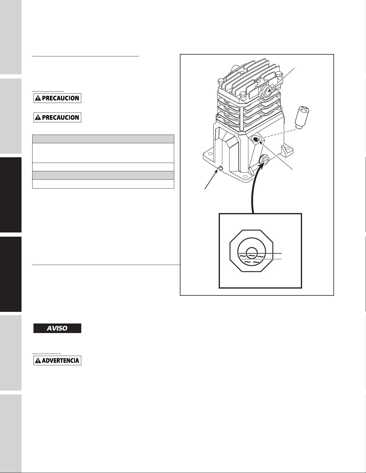
INSTALACIÓN (CONTINUACIÓN)
Instalación del filtro de entrada de aire
Atornille el filtro de entrada de aire incluido en el puerto
SEGURIDAD /
de entrada de la bomba de hierro fundido como se indica
PARA COMENZAR
en la Figura 6.
Lubricacion
ESTA UNIDAD NO TIENE ACEITE.
hasta el centro del calibrador visual (ver Figura 6).
Si utiliza cualquier otro tipo de
cabezal y dañar las válvulas.
ESPECIFICACIONES
Aceite recomendado (2 opciones)
Aceite no detergente para compresor de una sola viscosidad
SAE 30 ISO100. Número de parte ST125303AV (0.47 L) o
ST126701AV (3.79 L).
Aceite sintético 10W30 como el Mobil 1® o CE0032 (0.95 L).
Capacidad de aceite
Aproximadamente 0,25 L.
Llene la bomba con aceite hasta el centro del calibrador
visual usando la abertura de llenado de aceite (ver Figura
6). NO llene la bomba a través de la abertura de la tapa de la
válvula de aire ya que esto podría causar una pérdida de aceite y
que la misma rociara durante el funcionamiento.
NOTA: puede haber algo de aceite residual aún en la
bomba por las pruebas realizadas en la fábrica que dejan
una capa fina en el calibrador visual, sin embargo, no hay
aceite suficiente para hacer funcionar la unidad.
Puerto de
entrada
Antes de utilizar el compresor. Llene
aceite podría disminuir la duración del
Área de
llenado
de aceite
Tapón del
drenaje
del aceite
Lleno
Bajo
FUNCIONAMIENTO
IMPORTANTE: Chequée la rotacion del motor antes de
OPERACION MONTAJE / INSTALACION
utilizar el compresor.
Todos los cabezales que requieren lubricación expulsan
agua condensada y aceite con el aire comprimido. Por lo
tanto, en ciertos casos, deberá instalar le filtros adecuados
para eliminar agua/aceite.
Si no le instala los filtros adecuados
ocasionarle daños a al aire operado equipos
Proteccion
Antes de utilizar el compresor le
DE PROBLEMAS
IDENTIFICACION
Todas las piezas que se mueven deben estar protegidas con
una tapa. Debe colocarle todas las tapas al sistema eléctrico
antes de encender el compresor.
Medidor visual
Figura 6 - Lubricacion
para eliminar el agua/aceite podría
debe instalar la tapa de las bandas.
/ REPARACION
MANTENIMIENTO
Sp10
Page 57

FUNCIONAMIENTO (CONTINUACIÓN)
Periodo De Uso Incial Recomendado
El compresor debe operarse de manera continua a 6.2 bar o menos por una hora para permitir que los
anillos de pistón se asienten apropiadamente.
1. Abra la llave de drenaje del tanque y deje que el compresor funcione durante 60 minutos.
2. Apague el compresor y cierre la llave de drenaje. El compresor está listo para funcionar.
Si el compresor se opera bajo condiciones húmedas por
períodos cortos de tiempo, la humedad se condensará
en el cárter y hará Que el aceite se vea cremoso. El aceite
contaminado con agua condensada no proporcionará una
lubricación adecuada y debe cambiarse de inmediato. El uso
de aceite contaminado dañará los rodamientos, pistones,
cilindros y anillos y no está cubierto por la garantía. Para
evitar la condensación del agua en el aceite, haga funcionar
periódicamente el compresor con una presión de tanque
cercana a 8.3 bar para compresores de etapa única abriendo
la válvula de purga o una válvula de aire conectada al tanque
o la manguera. Haga funcionar la bomba durante una hora
continua al menos una vez a la semana o con más frecuencia si
vuelve a ocurrir la condensación.
IMPORTANTE: Cambie el aceite después de las primeras 50 horas de operación y cada 200 horas después.
Descarga
(detrás del interruptor
Válvula de
de presión)
alivio de
seguridad
Figure 7 - Pressure Switch
PARA COMENZAR
ESPECIFICACIONES
SEGURIDAD /
Presostato, Arranque - Paro
NOTA: Los compresores de etapa única tienen una presión de operación máxima de 9,3 bar. Nunca exceda
esta presión en ninguno de los controles de los componentes.
La unidad de compresión se inicia y se detiene basándose en la configuración del presostato preestablecida
de 7,2 bar de inicio y 9,3 bar de corte. El interruptor de presión contiene una pequeña válvula de descarga
que permite la salida del aire para que el motor pueda arranacr fácilmente (ver Figura 7).
La válvula de descarga en el presostato silbará durante un breve período de tiempo cuando el compresor
se apague. Esto libera el cabezal y la tubería de salida de toda presión y permite que el compresor se inicie
sin carga. Debido a que los compresores tienen una alta torsión de arranque, es necesaria una válvula de
descarga para iniciar el compresor correctamente.
La válvula de retención es una válvula de un solo sentido que mantiene el aire en el tanque cuando
la unidad se apaga. La forma más fácil de determinar si la válvula de retención no está funcionando
correctamente es asegurarse de que la válvula de descarga del presostato deje de silbar luego de que se
apaga el compresor. El silbido debe durar por varios segundos y luego dejar de sonar.
Respirador De La Caja Del Cigüeñal
Durante condiciones severas de funcionamiento o al encenderlo por primera vez, podría crearse una
acumulación de aceite en el orificio del respirador de la caja del cigüeñal. Ésto es nornal y disminuirá con el
uso, ya que los anillos se fijarán.
Drenaje Del Tanque
Se debe drenar la condensación del tanque
diariamente. En los modelos de la serie de taller use el
drenaje manual del tanque (ver Figura 8).
OPERACIONMONTAJE / INSTALACION
IDENTIFICACION
DE PROBLEMAS
Sp11
Figura 8 - Drenaje manual del tanque
MANTENIMIENTO
/ REPARACION
Page 58

GUÍA DE DIAGNÓSTICO DE AVERÍAS
Baja presión de descarga 1. La demanda de aire excede la
PARA COMENZAR
SEGURIDAD /
ESPECIFICACIONES
El sobrecalentamiento de la
bomba derrite el filtro
Ruido excesivo (golpeteo) 1. Motor o polea del compresor floja 1. Es común que el motor o las poleas del compresor
OPERACION MONTAJE / INSTALACION
Aceite excesivo en el aire de
descarga.
NOTA: En un compresor
lubricado con aceite siempre
hay una pequeña cantidad de
aceite en el flujo de aire.
Agua en el aire de salida o en
DE PROBLEMAS
IDENTIFICACION
/ REPARACION
MANTENIMIENTO
el tanque
El motor zumba y funciona
lentamente o no funciona en lo
absoluto
PROBLEMA POSIBLE(S) CAUSA(S) ACCIÓN A TOMAR
capacidad de la bomba
2. Pérdidas de aire 2. Escuche para detectar pérdidas de aire. Aplique
3. Entrada de aire restringida 3. Limpie el elemento del filtro de aire.
4. Juntas defectuosas 4. Reemplace cualquier junta que pruebe estar
5. Válvulas dañadas o con pérdidas. 5. Quite el cabezal e inspecciónelo para detectar
1. No está la junta de aislamiento entre
el filtro y el cabezal
2. Válvulas rotas/juntas defectuosas 2. Reemplace las válvulas o instale una junta nueva.
2. Falta de aceite en el cárter 2. Controle si el nivel de aceite es el adecuado; si está
3. Biela gastada 3. Reemplace la biela. Mantenga el nivel de aceite y
4. Diámetros del eje del émbolo
desgastados
5. El émbolo pega contra la placa de la
válvula
6. Válvula de verificación ruidosa en el
sistema del compresor
1. Aros del émbolo desgastados 1. Reemplácelos con aros nuevos. Mantenga el nivel de
2. La entrada de aire del compresor está
restringida
3. Demasiado aceite en el compresor 3. Escúrralo hasta que alcance el nivel de lleno.
4. Viscosidad del aceite equivocada 4. Utilice aceite Mobil 1® 10W-30.
1. Operación normal. La cantidad de
agua aumenta con el clima húmedo
1. Utiliza un cordón de extensión 1. No utilice un cordón de extensión. Utilice una
2. Malfuncionamiento de la válvula de
verificación o de la válvula de descarga
3. Voltaje bajo 3. Verifique con un voltímetro, revise el interruptor de
4. Malfuncionamiento del interruptor
presión, los contactos no se cierran
1. Reduzca la demanda de aire o utilice un compresor
de mayor capacidad.
una solución jabonosa a todos los accesorios y
conexiones. Aparecerán burbujas en los puntos
donde existan pérdidas. Ajuste o reemplace los
accesorios o conexiones con pérdidas.
defectuosa al inspeccionarla.
posibles roturas de la válvula, válvulas desalineadas,
asientos de válvulas dañados, etc. Reemplace las
piezas defectuosas y vuelva a armar.
Instale una nueva junta para el
cabezal cada vez que éste sea
quitado.
1. Instale la junta.
flojas causen golpeteo de los compresores. Ajuste los
tornillos de los sujetadores de la polea y los tornillos
de montaje.
bajo, verifique la posibilidad de que los cojinetes
estén dañados. El aceite sucio puede causar un
desgaste excesivo.
cambie el aceite con más frecuencia.
4. Quite los ensamblajes del émbolo del compresor e
inspecciónelos para detectar un desgaste excesivo.
Reemplace el eje del émbolo(s) si está excesivamente
desgastado o según necesario. Mantenga el nivel de
aceite y cambie el aceite con más frecuencia.
5. Quite el cabezal del compresor y la placa de la
válvula e inspeccione para detectar depósitos de
carbón u otros elementos extraños en la cabeza del
émbolo. Vuelva a colocar el cabezal y la placa de
la válvula utilizando una junta nueva. Consulte la
sección de lubricación para el aceite recomendado.
6. Reemplácela.
No desarme la válvula de
verificación con presión de aire
en el tanque.
aceite y cambie el aceite con más frecuencia.
2. Limpie el filtro. Verifique otras restricciones en el
sistema de entrada.
1. Drene el tanque con más frecuencia. Al menos
diariamente.
2. Agregue un filtro
manguera de aire más larga con un diámetro mayor.
2. Reemplace la válvula de verificación, la válvula de
descarga o el interruptor de presión.
No desarme la válvula de
verificación con presión de aire
en el tanque.
reajuste del motor. Si este se dispara varias veces,
busque la causa y corríjala. Consulte el siguiente
punto.
4. Repare o reemplace el interruptor de presión.
Sp12
Page 59

GUÍA DE DIAGNÓSTICO DE AVERÍAS (CONTINUACIÓN)
PROBLEMA POSIBLE(S) CAUSA(S) ACCIÓN A TOMAR
El mecanismo de reajuste
interrumpe el funcionamiento
constantemente o los fusibles se
funden con frecuencia
El tanque no mantiene la
presión cuando el compresor
está apagado y la válvula de
cierre está cerrada
El interruptor de presión tira
continuamente aire por la
válvula de descarga
El interruptor de presión no
libera el aire cuando la unidad
de apaga
Vibración excesiva 1. Ajustadores flojos 1. Ajústelos.
1. Demasiados aparatos en el mismo
circuito
2. Tamaño incorrecto del fusible o del
disyuntor
3. Malfuncionamiento de la válvula de
verificación
4. Interruptor de presión fijado
demasiado alto
5. Cableado flojo 5. Verifique todas las conexiones eléctricas
6. Malfuncionamiento del motor 6. Reemplace el motor.
1. Válvula desgastada 1. Reemplace la válvula.
2. Verifique todas las conexiones y los
accesorios para detectar fugas
3. Revise el tanque para detectar fisuras
o perforaciones
1. Malfuncionamiento de la válvula 1. Reemplace la válvula de verificación si la válvula de
1. Malfuncionamiento de la válvula de
descarga en el interruptor de presión
2. La correa necesita ser reempla zada 2. Reemplace la correa con otra del tamaño adecuado.
3. Alineación de la correa 3. Alinee el volante y la polea.
1. Use sólo el compresor de aire en el circuito.
2. Asegúrese de que los fusibles o los disyuntores sean
del tamaño adecuado.
3. Reemplace la válvula de verificación
No desarme la válvula de
en el tanque.
4. Ajuste o reemplace el interruptor.
No desarme la válvula de
en el tanque.
2. Apriete.
3. Reemplace el tanque. Nunca repare un tanque
dañado
descarga tiene perdidas constantemente.
No desarme la válvula de
en el tanque.
1. Reemplace el interruptor de presión si éste no libera
la presión por un breve período de tiempo cuando se
apaga la unidad.
No desarme el interruptor
eltanque.
verificación con presión de aire
verificación con presión de aire
verificación con presión de aire
depresión si hay presión en
PARA COMENZAR
ESPECIFICACIONES
SEGURIDAD /
OPERACIONMONTAJE / INSTALACION
Sp13
IDENTIFICACION
DE PROBLEMAS
MANTENIMIENTO
/ REPARACION
Page 60
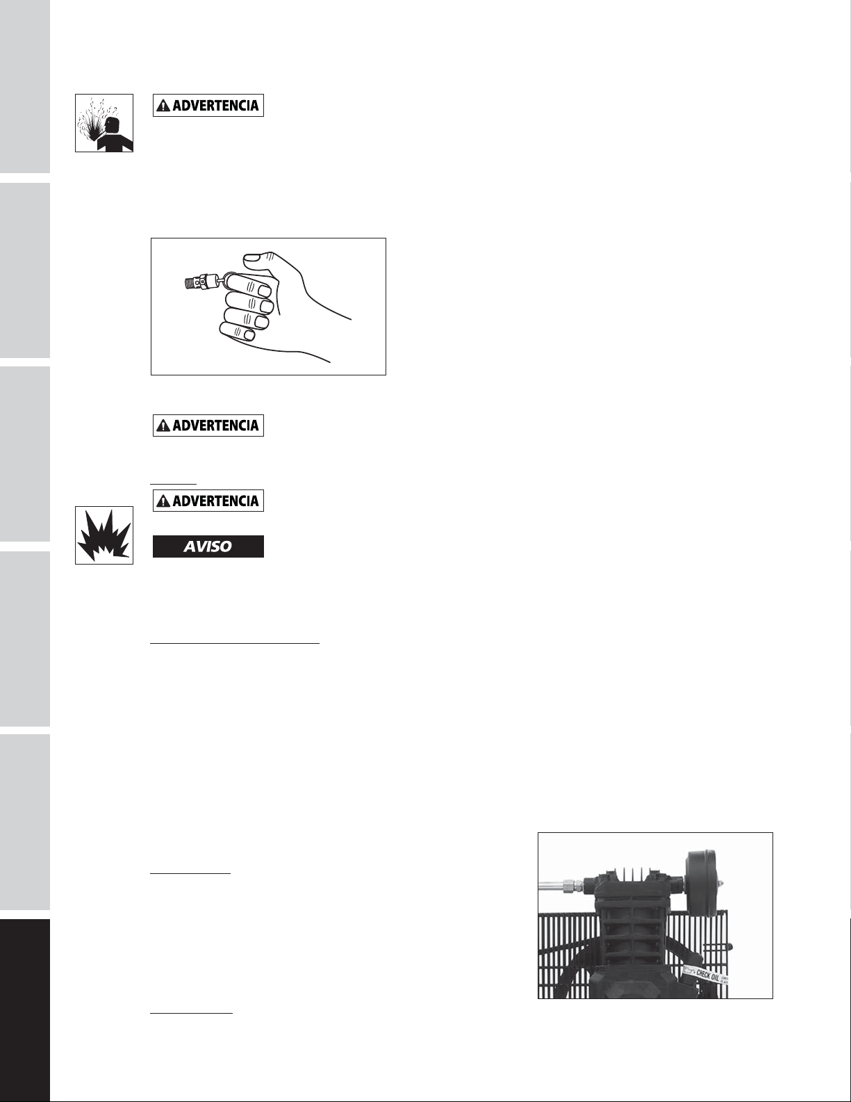
INSTRUCCIONES DE MANTENIMIENTO E INSPECCIÓN
PARA COMENZAR
SEGURIDAD /
ESPECIFICACIONES
Desconecte el cordón eléctrico, amárrelo y aléjelo del tomacorrientes, después libere toda la
darle cualquier tipo de mantenimiento.
presión del tanque antes de tratar de instalar el compresor, darle servicio, moverlo de sitio o
Para mantener el funcionamiento eficiente del sistema del compresor, chequée el filtro de aire y mida el
nivel del aceite antes de cada uso. La válvula de seguridad ASME también se debe chequear a diario (Vea
la Figura 9). Hále el anillo de la válvula de seguridad y déjelo que regrese de nuevo en su posición original.
Esta válvula automáticamente li-bera el aire del tanque, si la presión excede el nivel máximo fijado de
fábrica. Si hay una fuga de aire después que ha soltado el anillo, o si la válvula está atascada y no la puede
activar con el anillo, deberá reemplazar la válvula de seguridad ASME.
Figura 9 - Válvula de seguridad ASME
No modifique la válvula de retención ASME.
Tanque
¡Nunca trate de reparar o modificar el tanque! Si lo suelda, taladra o modifica de cualquier otra
tanques desgastados, rotos o dañados.
manera, el tanque se debilitará y se podría dañar al romperse o explotar. Siempre remplace los
OPERACION MONTAJE / INSTALACION
DE PROBLEMAS
IDENTIFICACION
Drene el líquido del tanque diariamente.
El tanque se debe inspeccionar cuidadosamente por lo menos una vez al año. Cerciórese de que no haya
ranuras en las soldaduras. De haberlas, libere la presión del tanque inmediatamente y reemplácelo.
Lubricación del Compresor
Vea la sección de Funcionamiento Añádale aceite al cabezal cuando sea necesario. Debe cambiar el aceite y
el filtro cada 3 meses o después de 200 horas de funcionamiento; lo que ocurra primero.
Si el compresor se utiliza bajo condiciones húmedas por períodos cortos, la humedad se condensará en
la caja del cigüeñal y ocasionará que el aceite luzca cremoso. El aceite contaminado por el agua no le
proveerá la lubricación adecuada y lo debe cambiar inmediatamente. Si usa aceite contaminado, los
cojinetes, pistones, cilindros y anillos se dañarán y estos daños no están cubiertos por la garantía.
Para evitar
la condensación del agua en el aceite, haga funcionar periódicamente el compresor con una presión de
tanque cercana a 8.3 bar para compresores de etapa única abriendo la válvula de purga o una válvula de
aire conectada al tanque o la manguera.
Deje que el cabezal funcione por una hora en estas condiciones
por lo menos una vez a la semana, o con más frecuencia, en caso de que el problema ocurra.
IMPORTANTE: Cámbiele el aceite después de 50 horas de operación.
Filtro de aire
Nunca utilice el cabezal del compresor sin instalarle el filtro de la
entrada de aire o con un filtro obstruído. El elemento del filtro
de aire debe verificarse mensualmente (verFigura 10). Si utiliza
el compresor con el filtro sucio, podría aumentar el consumo de
aceite y la contaminación con aceite del aire expulsado. Si el filtro
de aire está sucio, debe reemplazarse.
/ REPARACION
MANTENIMIENTO
Componente
Figura 10 - Filtro de aire
Corte el suministro eléctrico y limpie la cabeza del cilindro, el motor, las aspas del ventilador, las líneas de
aire, el enfriador posterior y el tanque una vez al mes.
Sp14
Page 61

INSTRUCCIONES DE MANTENIMIENTO E INSPECCIÓN (CONTINUACIÓN)
Correa
Apague el compresor, cerciórese de que el interruptor no se pueda activar y después libere la
presión del tanque, para evitar que la unidad se mueva sin previo aviso.
Chequée la tensión de las bandas cada 3 meses. Ajuste la tensión de las bandas para permitir una deflección
de9,5 mm a 12,7 mm (3/8 pulg - 1/2 pulg) al ejercer una presión normal con el dedo. Igualmente, debe
alinear las bandas usando como referencia un objeto recto que toque el volante y dos puntos del borde a
ambos lados del volante. Las bandas deben estar paralelas a esta línea recta de referencia (vea la Figura 11).
Las distancias A, B y C deben ser iguales para asegurar que las bandas estén alineadas adecuadamente. Las
ranuras en la base le permiten mover el motor, en ambas direcciones, para ajustar la tensión de las bandas.
Polea del
motor
Motor
AB
Compresor de aire
Volante
Borde recto
PARA COMENZAR
ESPECIFICACIONES
SEGURIDAD /
Tornillo de fijación
C
Figura 11 - Vista superior
Retiro del protector de banda
Al retirar el protector de banda delantero para
clips de sujeción y reemplácelos si están dañados o si el clip puede
quitarse sin herramientas.
inspeccionar o cambiar las bandas, revise los
Retiro de los clips de sujeción
1. Usando una llave inglesa o pinzas, gire el clip 90°.
2. Jale el clip hacia afuera, separándolo del protector de
banda.
3. Realice el procedimiento a la inversa para reinstalar el clip
Figura 12
después de revisarlo.
Almacenamiento
Si va a almacenar el compresor por un período corto, cerciórese de que esté en su posición normal y en un
área fría y bien protegida.
Programa De Mantenimiento
SERVICIO NECESARIO DIARIAMENTE MENSUALMENTE TRIMESTRALMENTE
Chequée la válvula de seguridad
Drene el tanque (Vea la Figura 8)
Mida el nivel de aceite
Limpie o cambie el filtro de aire
Chequée el sistema de enfriamiento interno
Limpie los componentes
Chequée la tensión de las bandas
Cambie el aceite (Vea la Figura 6)
●
●
●
●
●
●
1
2
●
●
OPERACIONMONTAJE / INSTALACION
IDENTIFICACION
DE PROBLEMAS
MANTENIMIENTO
/ REPARACION
Sp15
Page 62

PARA COMENZAR
ILUSTRACION DE LAS PARTES DE REPARACION PARA LOS MODELOS VT6195 Y VT6395
16
29
32
14
15
20
19
21
17
22
17
24
9
9
SEGURIDAD /
ESPECIFICACIONES
OPERACION MONTAJE / INSTALACION
33
25 26
27
18
13
12
10
11
28
35
36
2
33
33
1
3
1
4
5
34
33
1
1
1
23
30
33
8
7
1
1
1
6
1
DE PROBLEMAS
IDENTIFICACION
Para refacciones, visite www.campbellhausfeld.com
24 horas al día, 365 días al año
Por favor proporcione la siguiente información:
- Número de modelo
- Número de serie (si lo tiene)
- Descripción de la parte y número que le corresponde en la lista de partes
/ REPARACION
MANTENIMIENTO
31
Sp16
Page 63

LISTA DE PARTES DE REPARACION PARA LOS MODELOS VT6195 Y VT6395
PARA COMENZAR
No. de
Ref. Descripción
1 CONJUNTO DE LA BOMBA 3HP VT VT4723 1
2 MOTOR ELÉCTRICO DE 3.2HP 240V MC019700SJ 1
3 TORNILLO DE CABEZA HEXAGONAL 5/16 PULG.-18 X 3/4 PULG. - 4
4 ARANDELA, 5/16 PULG. - 4
5 TUERCA CON ALA, 5/16 PULG.-18 - 4
6 TORNILLO AUTORROSCANTE, 5/16 PULG. - 12 - 4
7 PROTECTOR DE BANDAS, TRASERO BG218700AV 1
8 PROTECTOR DE BANDAS, DELANTERO BG218800AV 1
9 TUERCA DE BRIDA HEXAGONAL 10-24 - 4
10 POLEA 3.25" X 5/8" DIÁMETRO INTERNO PU012700AV 1
11 LLAVE DE 3/16 PULG. X 1 PULG. KE000900AV 1
12 TORNILLO DE 1/4 PULG.-20 X 1/2 PULG. - 1
13 NIPLE DE TUBERÍA, 1/4 PULG. NPT X 1.5 PULG. - 1
14 VÁLVULA DE RETENCIÓN CV221502AV 1
15 CONECTOR PARA TUBO QUICK CONNECT, 1/4 PULG. TUBERÍA X 1/8 PULG. NPT ST081301AV 1
16 TAPÓN, 1/4 PULG. NPT - 1
17 TUERCA DE COMPRESIÓN, 1/2 PULG. ST033001AV 2
18 VÁLVULA DE SEGURIDAD ASME, 150PSI V-215105AV 1
19 MEDIDOR, 300PSI GA031900AV 1
20 CONECTOR DE COMPRESIÓN, 1/2 PULG. NPT X 1/2 PULG. TUBERÍA - 1
21 CASQUILLO, 1/2 PULG. - 1
22 TUBO DE ESCAPE VT043300AP 1
23 TORNILLO ROSCANTE, 10-3/8 PULG. - 1
24 CASQUILLO MOLDEADO, 1/2 PULG. - 1
25 ABRAZADERA PARA INTERRUPTOR DE PRESIÓN CW209700AV 1
26 TORNILLO DE PINZA ST209800AV 1
27 TORNILLO AUTORROSCANTE DE CABEZA HEXAGONAL, 8 - 3/8 PULG. - 2
28 BANDA, AX48 -1
29 TUBO PTFE, 1/4 PULG. X 14 PULG. - 1
30 SOPORTE DE PROTECTOR DE BANDAS BG220400AV 1
31 VÁLVULA DE DRENAJE D-1403 1
32 INTERRUPTOR DE PRESIÓN CW209300AV 1
33 TORNILLO ROSCANTE, 5-5/8 PULG. - 5
34 CABLE DE ALIMENTACIÓN DEL MOTOR, 16 PULG. EC012800AV 1
35 TAPÓN DE PLÁSTICO, 3/4 PULG. NPT - 1
36
TANQUE ASME DE 60 GALONES AR236500CG 1
Número de
Parte: Cant.
ESPECIFICACIONES
SEGURIDAD /
OPERACIONMONTAJE / INSTALACION
Sp17
IDENTIFICACION
DE PROBLEMAS
MANTENIMIENTO
/ REPARACION
Page 64

ILUSTRACION DE LAS PARTES DE REPARACION PARA LOS MODELOS VT4923
PARA COMENZAR
SEGURIDAD /
ESPECIFICACIONES
20
17
16
OPERACION MONTAJE / INSTALACION
13
15
5
11
14
10
8
6
7
8
2
9
4
3
DE PROBLEMAS
IDENTIFICACION
Para refacciones, visite www.campbellhausfeld.com
24 horas al día, 365 días al año
Por favor proporcione la siguiente información:
- Número de modelo
- Número de serie (si lo tiene)
- Descripción de la parte y número que le corresponde en la lista de partes
/ REPARACION
MANTENIMIENTO
12
19
1
18
Sp18
Page 65

LISTA DE PARTES DE REPARACION PARA LOS MODELOS VT4923
No. de
Ref. Descripción Número de Parte: Cant.
1 CÁRTER -- 1
2 EMPAQUE DEL CÁRTER
3 RESPIRADERO VH901100AV 1
4 CILINDRO -- 1
5 EMPAQUE DEL CILINDRO
6 CONJUNTO DE VARILLA CONECTORA Y PISTÓN -- 2
7 JUEGO DE ANILLOS DE PISTÓN -- 2
8 RODAMIENTO DE BOLA -- 2
9 CIGÜEÑAL, RODAMIENTOS, VARILLAS, CONJUNTO DEL PISTÓN -- 1
10 EMPAQUE DE ANILLO
11 SELLO DE ACEITE -- 1
12 CONJUNTO DE TAPA DE RODAMIENTO -- 1
13 TORNILLO DE CABEZA HEXAGONAL M6 X 10 MM
14 CONJUNTO DE PLACA DE VÁLVULA VT491100AV 1
15 SELLO MOLDEADO PARA PLACA DE VÁLVULA
16 CABEZA DE CILINDRO Y SUJETADORES -- 1
17 CONJUNTO DEL FILTRO DE AIRE VH901700AV 1
18 TAPÓN DE DRENAJE DE ACEITE DE 1/8 PULG. - 27 -- 1
19 MIRILLA ST191700AV 1
20 ELEMENTO DEL FILTRO DE AIRE VH901800AV 1
KITS DE REFACCIONES
●
-- NO DISPONIBLE
✝
JUEGO DE EMPAQUES VT490900AV
DISPONIBLE EN FERRETERÍAS LOCALES
●
●
●
✝
●
PARA COMENZAR
1
1
ESPECIFICACIONES
SEGURIDAD /
1
4
1
OPERACIONMONTAJE / INSTALACION
Sp19
IDENTIFICACION
DE PROBLEMAS
MANTENIMIENTO
/ REPARACION
Page 66

Recordatorio: ¡Guarde su comprobante de compra con fecha para fines de la garantía! Adjúntela a este manual o archívela en
lugar seguro.
GARANTÍA LIMITADA
1. DURACIÓN: La bomba del compresor y el receptor de aire tienen una garantía de tres años a partir de la fecha de compra del
comprador original. El equilibro del paquete del compresor tiene una garantía de tres años a partir de la fecha de compra del
comprador original.
2. QUIEN OTORGA ESTA GARANTÍA (EL GARANTE: Campbell Hausfeld a Marmon/Berkshire Hathaway Company, 100 Production
Drive, Harrison, Ohio 45030. Visite www.campbellhausfeld.com
3. QUIEN RECIBE ESTA GARANTÍA (EL COMPRADOR): El comprador original (sin fines de reventa) del compresor de aire
CampbellHausfeld.
4. PRODUCTOS CUBIERTOS POR ESTA GARANTÍA: Compresores de aire VT6195 y VT6395 de Campbell Hausfeld.
5. COBERTURA DE LA GARANTÍA: Piezas y mano de obra para remediar los defectos de material y/o mano de obra con
excepción de lo que se indica a continuación.
6. LO QUE NO ESTÁ CUBIERTO POR ESTA GARANTÍA:
A. Las garantías implícitas, incluyendo aquéllas de comerciabilidad e IDONEIDAD PARA FINES PARTICULARES, ESTÁN
LIMITADAS A PARTIR DE LA FECHA DE COMPRA ORIGINAL DE ACUERDO CON LO ESPECIFICADO EN EL PÁRRAFO DE
DURACIÓN. En algunos estados no se permiten las limitaciones a la duración de una garantía implícita, por lo cual las
limitaciones antedichas pueden no ser aplicables en su caso.
B. CUALQUIER PÉRDIDA DAÑO INCIDENTAL, INDIRECTO O CONSECUENTE QUE PUEDA RESULTAR DE UN DEFECTO, FALLA
O MALFUNCIONAMIENTO DEL PRODUCTO CAMPBELL HAUSFELD. En algunos estados no se permite la exclusión o
limitación de daños incidentales o consecuentes, por lo tanto, en tales casos esta limitación o exclusión no es aplicable
C. Cualquier falla debida a:
1. Accidente o abuso del comprador
2. Instalación incorrecta
3. Equipo que no ha sido operado o mantenido de acuerdo con las instrucciones detalladas de Campbell Hausfeld
según lo detallado en el manual de operaciones que se entrega con el compresor.
4. Equipo que ha sido reparado o modificado sin autorización de Campbell Hausfeld.
D. Los servicios requeridos antes de la entrega tales como: ensamblaje, aceite o lubricantes y ajustes.
E. Los efectos del uso y desgasto normales.
F. Los motores de gasolina están específicamante excluidos de la cobertura de esta garantía limitada. El comprador debe
seguir las clausulas de la garantía otorgada por el fabricante del motor de gasolina que se suministra con el producto.
G. Equipo que ha sido dañado en el tránsito.
7. RESPONSABILIDADES DEL GARANTE BAJO ESTA GARANTÍA: Reparar o reemplazar, como lo decida el Garante, el compresor o
componentes que estén defectuosos, se hayan dañado o hayan dejado de funcionar adecuadamente, durante el período de
validez de la garantía. Las reparaciones cubiertas por la garantía se realizarán en la ubicación del comprador.
8. RESPONSABILIDADES DEL COMPRADOR BAJO ESTA GARANTÍA:
A. Suministrar prueba fechada de compra y la historia de mantenimiento del producto.
B. Tener cuidado al utilizar el producto, tal como se indica(n) en el (los) manual(es) del propietario.
C. Reparaciones que requieran tiempo adicional al horario normal de trabajo, o cualquier asunto que exceda la tarifa
normal de reembolso por mano de obra para reparaciones bajo la garantía del fabricante.
D. El tiempo requerido por cualquier control de seguridad, capacitación relacionada con seguridad, o asuntos similares
necesarios para que el personal de servicio pueda tener acceso a las instalaciones.
E. La ubicación de la unidad debe tener espacio suficiente para que el personal de servicio pueda realizar reparaciones y
debe ser fácilmente accesible.
9. CUÁNDO EFECTUARÁ EL GARANTE LA REPARACIÓN O REEMPLAZO CUBIERTO BAJO ESTA GARANTÍA: La reparación o
reemplazo dependerá del flujo normal de trabajo del centro de servicio y de la disponibilidad de repuestos.
Esta garantía limitada es válida sólo en los EE.UU., Canadá y México y otorga derechos legales específicos. Usted también puede
tener otros derechos que varían de un Estado a otro. o de un país a otro.
Sp20
 Loading...