

Page 1
Electric Pressure
Washer
Please read and save these instructions. Read carefully before attempting to assemble, install, operate or maintain the product described. Protect yourself and others by
observing all safety information. Failure to comply with instructions could result in
personal injury and/or property damage! Retain instructions for future reference.
IN463200AV 10/03
© 2003 Campbell Hausfeld
Specifications
PW1580 2550 1500 psi 1.7 GPM 14 Amps 120V 100˚F 25 lbs.
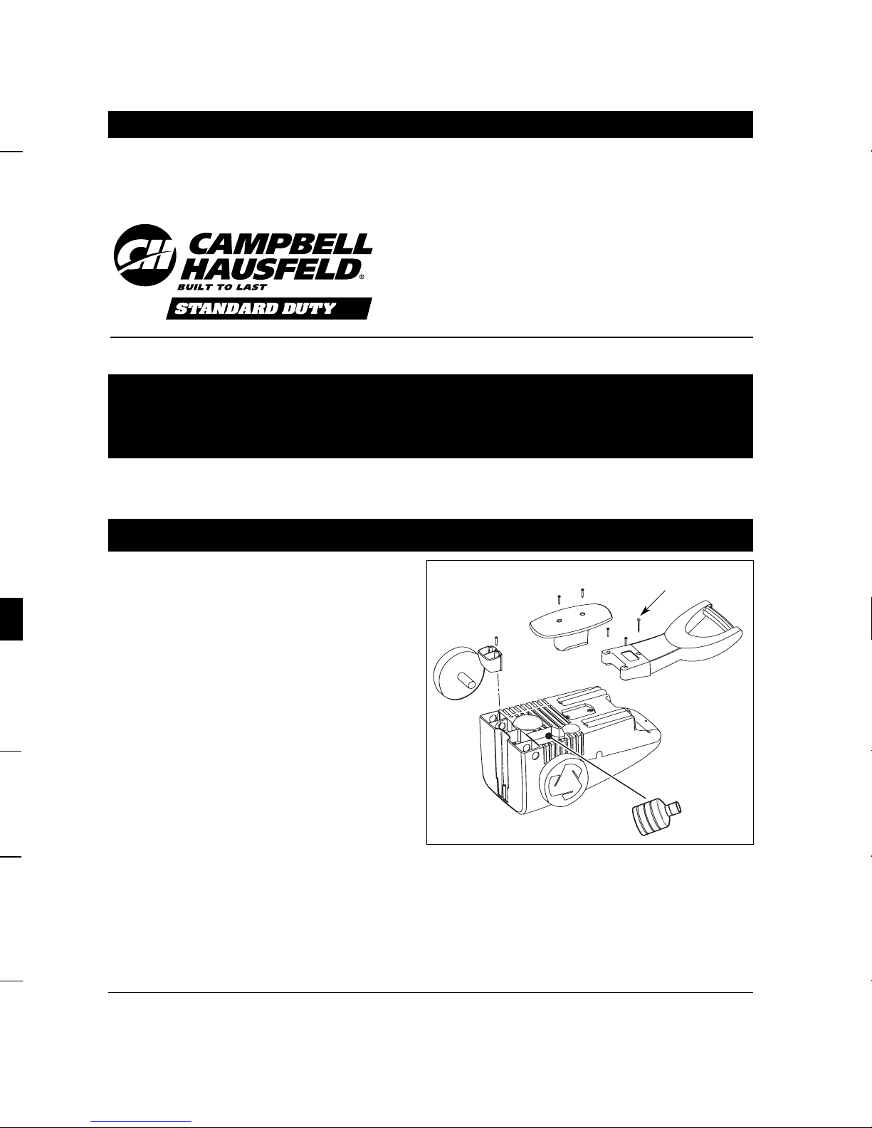
Assembly Instructions
Assembly Instructions and Parts List PW1580
1. Attach black handle with enclosed
screws as shown. The longest
screw goes into the top hole of
the handle.
2. Assemble wheels to the bottom of
pressure washer as shown.
3. Attach foot to bottom of pressure
washer as shown.
4. Attach hose and cord holder with
enclosed screws as shown.
5. Stand pressure washer upright on
wheels and foot. Put chemical suction tube in detergent bottle and
push detergent bottle into back of
pressure washer.
Figure 1
NOTE: REFER TO PRODUCT MANUAL
FOR ALL SAFETY INSTRUCTIONS
For parts, product & service information
visit www.chpower.com
Max Pressure Motor Maximum
with Power Inlet
Cleaning Standard Maximum (Single Water Unit
Model Power Lance Capacity Phase) Voltage Temp. Weight
Longest Screw
Page 2
1. Inserte la lanza en la pistola y gírela
en el sentido de las agujas del reloj
hasta que llegue a su tope, como se
muestra en la Figura 4.
2. Verifique que el interruptor de
energía esté en la posición "OFF"
("APAGADO").
13 mm
OUTLET
I
N
L
E
T
Figura 5
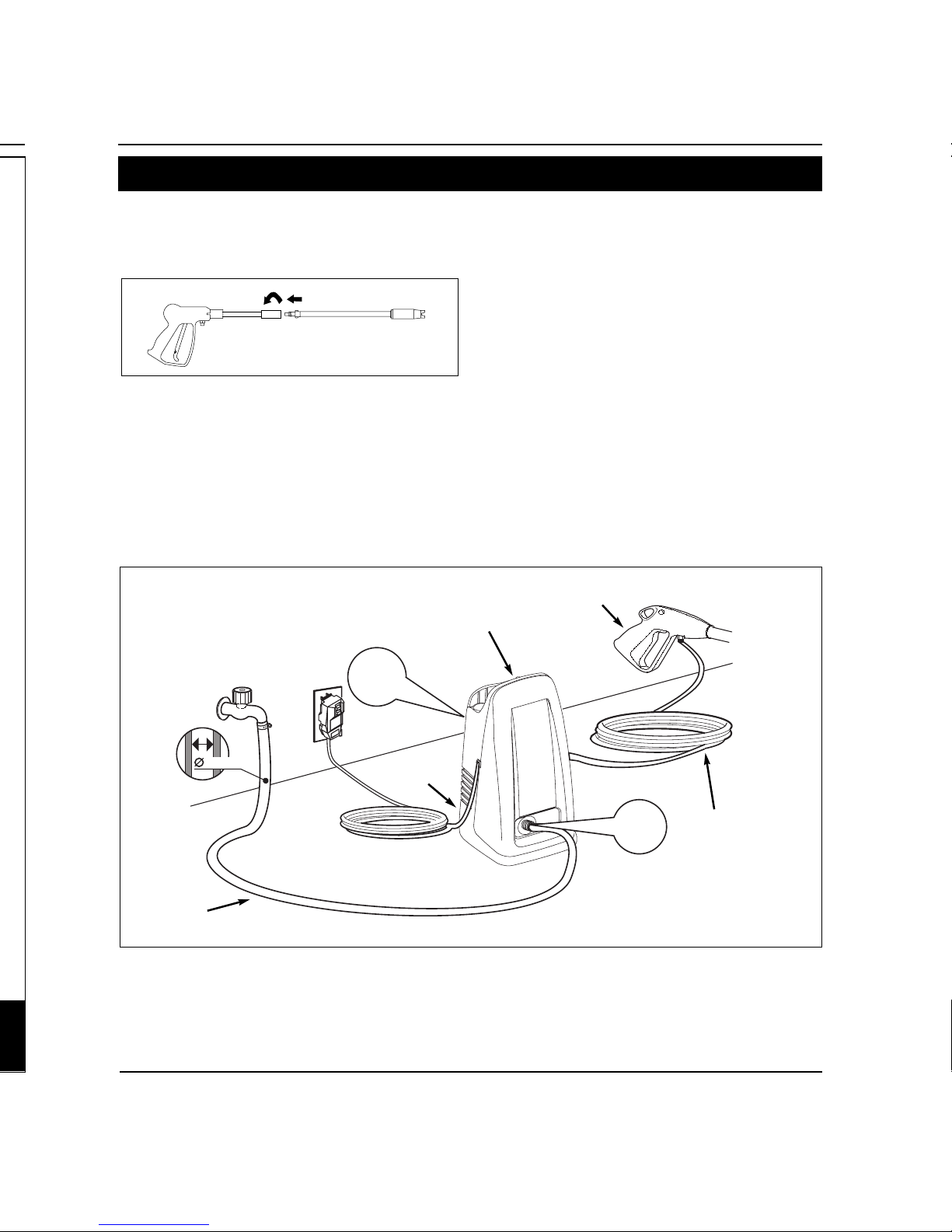
System Connection
Figura 4 - Conexión de la pistola y lanza
Manguera
de jardín
Cable de Corriente Eléctrica
Continuación
Instrucciones de Montaje y Lista de Piezas PW1580
2. SE DEBE HACER ESTO CADA VEZ QUE LA
UNIDAD SE ENCHUFE EN UN TOMACOR-
RIENTE.
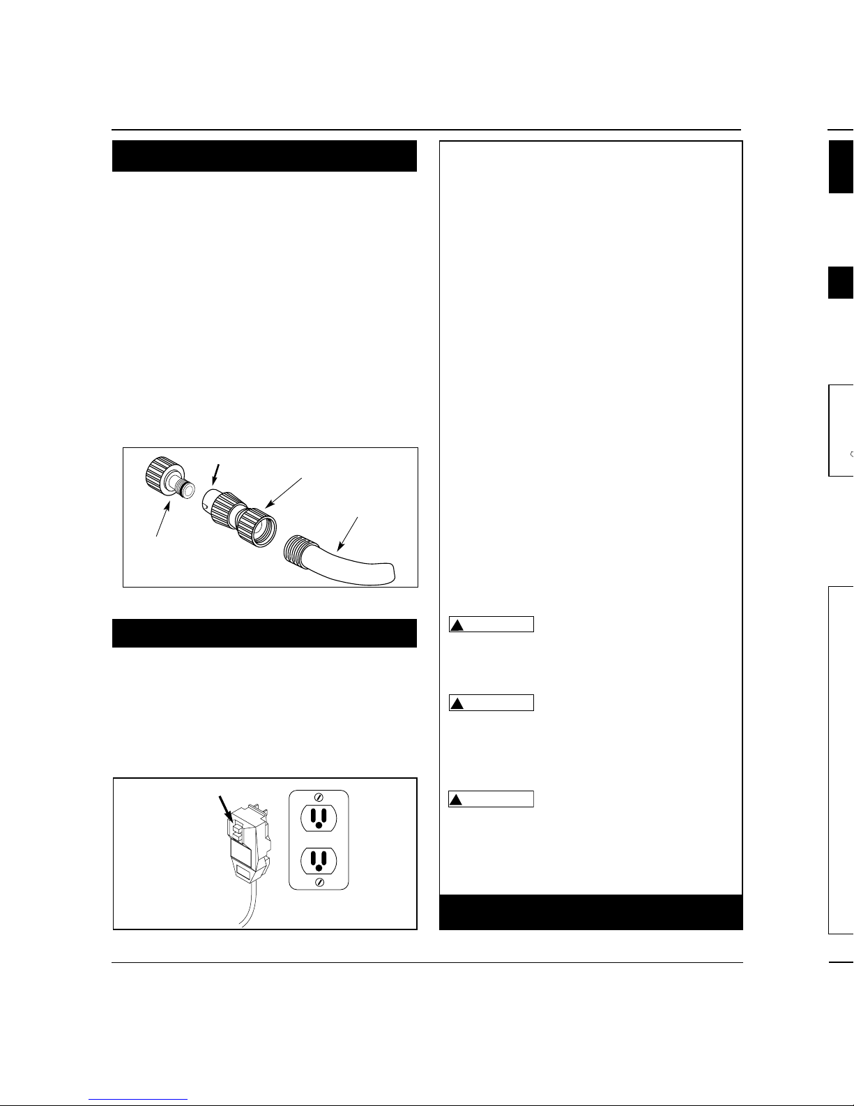
Garden Hose Connection
GARDEN HOSE CONNECTION
INSTRUCTIONS
1. Attach nipple adapter to inlet fitting
on the unit (this may already be
attached to the pump).
2. Attach quick connect fitting to garden hose.
3. Pull side “A” of quick connect fitting
toward garden hose and push onto
nipple adapter.
4. Push side “A” of quick connect fitting
towards nipple adapter and release.
"A"
Figure 2 - Garden Hose Connection
Quick Connect Fitting
Garden Hose
Nipple
Adapter
! IMPORTANT !
This pressure washer is equipped with a
microswitch sensitive to water flow. This
Instant Start/Stop switch (ISS) senses
water flow in the pump. When the trigger is released, water stops flowing
through the pump. The ISS then automatically turns the motor off to protect
pump from overheating.
OPERATION
1. Pull trigger on gun.
2. Turn the “ON/OFF” switch to “ON”.
3. Release trigger. The pressure washer
motor will stop running.
4. To spray again, pull trigger and motor
and pump will restart.
Note: Occasionally the motor may run
for a short time to bring fresh, cool
water into the pump even if trigger is
released. This is part of normal operation and will not damage the unit.
Always turn the
“ON/OFF” switch to “OFF”
then trigger gun to release hose pressure before unplugging power cord.
Risk of equipment dam-
age. Always make sure
the “ON/OFF” switch on the unit is
“OFF” and unit is unplugged prior to
storage.
Risk of Injection.
Unit will start spraying
when trigger is squeezed if on/off
switch is in “ON” position. Always
point gun in safe direction.
!
WARNING
!
CAUTION
!
CAUTION
Call 1-800-330-0712
for Technical Service
Assembly Instructions and Parts List PW1580
2
www.chpower.com
Power Cord
1. Plug the power cord into a grounded 120V outlet and press the reset
button as shown in Figure 3.
2. THIS MUST BE DONE EACH TIME THE
UNIT IS PLUGGED IN AN OUTLET.
Reset
Figure 3 - Grounded plug/reset button
Page 3
3
www.chpower.com
Assembly Instructions and Parts List PW1580
13 mm
OUTLET
I
N
L
E
T
Figure 5
1. Insert lance into the gun and turn
clockwise to positive stop as shown in
Figure 4.
2. Ensure that the power switch is in the
“OFF” position.
3. Attach the high pressure hose and
gun assembly to the unit.
4. Connect garden hose as explained
under Garden Hose Connection
Instructions.
5. Plug the power cord into a grounded
120V outlet, that is on a dedicated
circuit.
6. Turn water on.
7. Depress and hold the trigger on the
gun for one minute to release pressure and remove any air trapped in
the system.
8. Turn the “ON/OFF” switch to the
“ON” position.
NOTE: REFER TO PRODUCT MANUAL
FOR OPERATING INSTRUCTIONS
System Connection
Figure 4 - Gun/Lance Connection
Detergent
Bottle
On/Off
Switch
Gun
High
Pressure
Hose
Garden
Hose
Page 4
© 2003 Campbell Hausfeld
Sírvase leer y conservar estas instrucciones. Léalas cuidadosamente antes de intentar
armar, instalar, operar o efectuar mantenimiento al producto descrito. Protéjase a sí
mismo y a los demás observando toda la información de seguridad. ¡El no cumplir
con las instrucciones podría ocasionar lesiones personales y/o daños materiales!
Conserve estas instrucciones para futura referencia.
Especificaciones
Instrucciones de montaje y lista de piezas PW1580
PW1580 2340 103,43 bar 6,4 L/min 14 A 120V 38° C 11,3 kg
Modelo limpieza estándar Máxima (Monofásico) Voltaje de Entrada Unidad
Instrucciones de Montaje
1. Adjunte el mango negro con los
tornillos que se proporcionan, como
se muestra. El tornillo más largo se
coloca dentro del orificio superior
del mango.
2. Ensamble las ruedas a la parte inferi-
or de la lavadora a presión, como se
muestra.
3. Ensamble el pie a la parte inferior de
la lavadora a presión, como se mues-
tra.
4. Adjunte la manguera y el soporte del
cable con los tornillos que se propor-
cionan, como se muestra.
5. Apoye la lavadora a presión en posi-
ción vertical sobre las ruedas y la pata
de apoyo. Coloque el tubo de succión
de productos químicos en la botella
para detergente e introduzca la bote-
lla para detergente en la parte poste-
rior de la lavadora a presión.
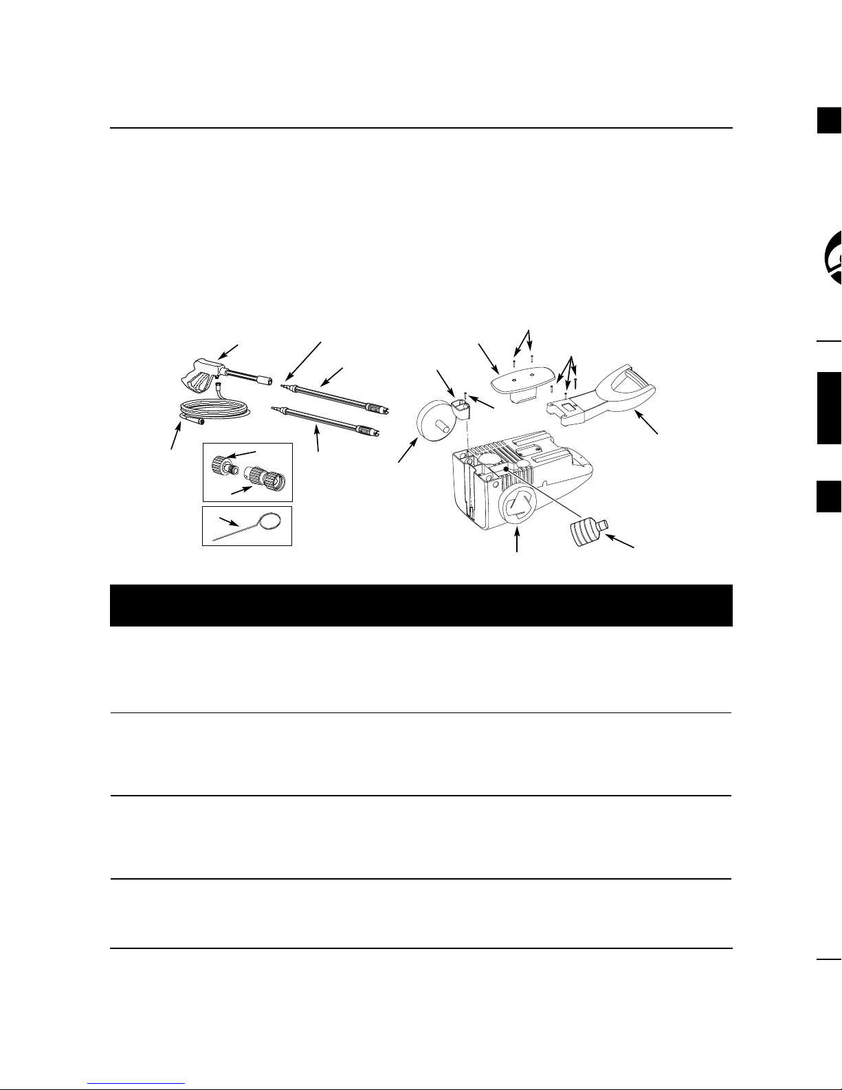
Assembly Instructions and Parts List PW1580
1 Adjustable pressure lance PM270000SV 1
2Turbo lance PM022621AV 1
3 Hose PM243600AV 1
4 Gun PM037201SJ 1
5 Nipple adapter PM022100AV 1
6 Quick connect fitting PM020600SV 1
7Tip cleaner PM008500AV 1
8 Bottle PM270010SV 2
9 Detergent bottle cap (not shown) PM270020SV 1
10 Wheel PM270030SV 2
11 Front support PM270040SV 1
12 Hose and cord holder PM270050SV 1
13 Handle PM270060SV 1
14 Hardware pack PM270070SV 1
15 O-ring PM232200SV 1
1
8
4
2
3
5
6
7
12
11
13
14
10
4
www.chpower.com
For Replacement Parts,
Call 1-800-330-0712
Replacement Parts List
Please provide following information:
-Model number
-Serial number (if any)
-Part description and number as
shown in parts list
Address parts correspondence to:
The Campbell Group / Parts Dept.
100 Production Drive
Harrison, OH 45030 U.S.A.
Ref. Part
No. Description Number Qty.
15
10
14
14
Page 5

Pulvérisateur de
Lavage Électrique
Si’il vous plaît lire et conserver ces instructions. Lire attentivement avant de monter,
installer, utiliser ou de procéder à l’entretien du produit décrit. Se protéger ainsi que les
autres en observant toutes les instructions de sécurité, sinon, il y a risque de blessure et /
ou dégâts matérials? Conserver ces instructions comme référence.
Instructions de Montage et Liste de Pièces de Rechange
PW1580
1. Fixer la poignée noire avec les vis
fournies, tel qu'illustré. La vis la
plus longue va dans le trou
supérieur de la poignée.
2. Monter les roues au bas du pulvérisateur de lavage, tel qu'illustré.
3. Fixer le pied au bas du pulvérisateur,
tel qu'illustré.
4. Fixer le porte tuyau et cordon avec
les vis fournies, tel qu'illustré
5. Relever le pulvérisateur de lavage
sur les roues et le pied. Mettre le
tube d'aspiration de produits chimiques dans la bouteille de détergent
et pousser la bouteille dans la section arrière du pulvérisateur.
REMARQUE: SE RÉFÉRER AU MANUEL DU PRODUIT
POUR TOUTES LES INSTRUCTIONS DE SÉCURITÉ
5Fr
Spécifications
PW1580 2550 10342 kPa 6,4 L/min 14 A 120V 38° C 11,3 kg
Instructions de Montage
IN463200AV 10/03
© 2003 Campbell Hausfeld
Pression Puissance Température
Max avec du Max. Poids
Pouvoir de Lance Capacité Moteur d’Eau du
Modèle nettoy age Standarde Maximum (Monophasé) Tension d’Arrivée Modèle
Figure 1
Vis la plus longue
Page 6

Instructions de Montage et Liste de Pièces de Rechange PW1580
1. Introduire la lance dans le pistolet et
tourner au sens des aiguilles d’une
montre à l’arrêt positif tel qu’indiqué
sur la Figure 4.
2. S’assurer que l’interrupteur soit dans
la position OFF (hors circuit).
13 mm
OUTLET
I
N
L
E
T
Figure 5
Branchement du Système
Figure 4 - Branchement de Pistolet/Lance
Tuyau
d’Arrosage
Cordon (
Suite)
2. ON DOIT LE FAIRE CHAQUE FOIS
QU’ON BRANCHE L’UNITÉ DANS UNE
PRISE.
Instructions de Montage et Liste de Pièces de Rechange PW1580
6 Fr
! IMPORTANT !
Ce pulvérisateur de lavage est équipé
d’un microrupteur sensible au débit
d’eau. Cet interrupteur de Marche/Arrêt
Instantané (Instant Start/Stop - ISS) est
sensible au débit d’eau dans la pompe.
Quand la gâchette est lâchée, le débit
d’eau à travers la pompe s’arrête. Le ISS
coupe le moteur automatiquement afin
de protéger la pompe contre le surchauffage.
FONCTIONNEMENT
1. Tirez la gâchette du pistolet.
2. Tourner l’interrupteur à “ON” (en
marche)
3. Lâcher la gâchette. Le moteur du pulvérisateur de lavage s’arrêtera.
4. Pour pulvériser de nouveau, tirer sur la
gâchette. Le moteur et la pompe se
remettront en marche.
Remarque: Le moteur pourrait fonctionner de temps en temps afin de fournir de
l’eau fraîche à la pompe (même si la
gâchette n’est pas actionnée). Ceci est
normal et n’endommagera pas le modèle.
Toujours tourner
l’interrupteur
“ON/OFF” (marche/arrêt) à la position
“OFF” (arrêt), et ensuite appuyer sur la
gâchette pour dissiper la pression avant
de débrancher le cordon d’alimentation.
Risque de
dommage à
l’équipement. Assurez-vous toujours
que l’interrupteur “ON/OFF”
(MARCHE/ARRÊT) de l’appareil est en
position ”OFF” et que l’appareil est
débranché avant de le ranger.
Risque d’injection.
Le modèle pulvérisera lorsque la gâchette est actionnée si
l’interrupteur “ON/OFF” (MARCHE/
ARRÊT) est dans la position “ON” (EN
MARCHE). Toujours pointer le pistolet
dans une direction hors de danger.
!
AVERTISSEMENT
!
ATTENTION
!
ATTENTION
Appelez 1-800-330-0712
pour le Service Technique
Branchement du Tuyau
d’Arrosage
"A"
Figure 2 - Branchement de Tuyau
d’Arrosage
Raccord Rapide
Tuyau
d’Arrosage
Raccord
Intermédiaire
INSTRUCTIONS DE BRANCHEMENT
DU TUYAU D’ARROSAGE
1. Fixer le raccord intermédiaire au raccord d’admission sur le modèle (ceci
pourrait déjà être fixé à la pompe).
2. Brancher le raccord rapide au tuyau
d’arrosage.
3. Tirer le côté “A” du raccord rapide
vers le tuyau d’arrosage et le pousser
sur le raccord intermédiaire.
4. Pousser le côté “A” du raccord rapide
vers le raccordement intermédiaire et
relâcher.
Cordon
1. Branchez le cordon dans une prise
mise à la terre de 120 V et appuyez
sur le bouton de réinitialisation tel
qu’illustré à la Figure 3.
Reset
Réinitialisation
Figure 3 - Prise de terre/réinitialisation
Page 7

7Fr
Instructions de Montage et Liste de Pièces de Rechange PW1580
1. Introduire la lance dans le pistolet et
tourner au sens des aiguilles d’une
montre à l’arrêt positif tel qu’indiqué
sur la Figure 4.
2. S’assurer que l’interrupteur soit dans
la position OFF (hors circuit).
13 mm
OUTLET
I
N
L
E
T
Figure 5
Branchement du Système
Figure 4 - Branchement de Pistolet/Lance
Interrupteur
On/Off
(Marche/
Arrêt)
Pistolet
Tuyau
Haute
Pression
Tuyau
d’Arrosage
3. Brancher le tuyau haute pression et
le montage de pistolet au modèle.
4. Brancher le tuyau d’arrosage selon
les directives: Instructions de
Branchement du Tuyau
d’Arrosage.
5. Branchez le cordon dans la prise mise à
la terre de 120V, qui est sur un circuit
spécialisé.
6. Faire circuler l’eau.
7. Appuyer sur et tenir la gâchette du
pistolet pendant une minute afin de
dissiper la pression et d’enlever l’air
emprisonné dans le système.
8. Tourner l’interrupteur “ON” (en
marche).
REMARQUE: SE RÉFÉRER AU
MANUEL DU PRODUIT POUR LES
INSTRUCTIONS D’OPÉRATION
Cordon (
Suite)
2. ON DOIT LE FAIRE CHAQUE FOIS
QU’ON BRANCHE L’UNITÉ DANS UNE
PRISE.
Bouteille de
détergent
Page 8

1 Lance à pression réglable PM270000SV 1
2 Lance turbo PM022621AV 1
3Tuyau PM243600AV 1
4 Pistolet PM037201SJ 1
5 Raccord intermédiaire PM022100AV 1
6 Raccord rapide PM020600SV 1
7 Nettoyeur de buse PM008500AV 1
8 Bouteille PM270010SV 2
9 Bouchon de bouteille de détergent (non illustré) PM270020SV 1
10 Roue PM270030SV 2
11 Support avant PM270040SV 1
12 Porte tuyau et cordon PM270050SV 1
13 Poignée PM270060SV 1
14 Paquet de quincaillerie PM270070SV 1
15 Joint torique PM232200SV 1
8Fr
Instructions de Montage et Liste de Pièces de Rechange PW1580
Liste de Pièces de Rechange
Pour Pièces de Rechange,
Appelez 1-800-330-0712
S’il vous plaît fournir l’information suivante:
-Numéro de Modèle
-Numéro de Série (si applicable)
-Description et numéro de la pièce indiqués
sur la liste de pièces de rechange
Correspondance:
The Campbell Group / Parts Dept.
100 Production Drive
Harrison, OH 45030 U.S.A.
No de No de
Réf. Description Pièce Qté.
Si’il vous plaît lire et conserver ces instructions. Lire attentivement avant de monter,
installer, utiliser ou de procéder à l’entretien du produit décrit. Se protéger ainsi que les
autres en observant toutes les instructions de sécurité, sinon, il y a risque de blessure et /
ou dégâts matérials? Conserver ces instructions comme référence.
Instructions de Montage et Liste de Pièces de Rechange
1. Fixer la poignée noire avec les vis
fournies, tel qu'illustré. La vis la
plus longue va dans le trou
supérieur de la poignée.
2. Monter les roues au bas du pul-
vérisateur de lavage, tel qu'illustré.
3. Fixer le pied au bas du pulvérisateur,
tel qu'illustré.
4. Fixer le porte tuyau et cordon avec
les vis fournies, tel qu'illustré
5. Relever le pulvérisateur de lavage
sur les roues et le pied. Mettre le
tube d'aspiration de produits chim-
iques dans la bouteille de détergent
et pousser la bouteille dans la sec-
tion arrière du pulvérisateur.
Spécifications
PW1580 2550 10342 kPa 6,4 L/min 14 A 120V 38° C 11,3 kg
Instructions de Montage
© 2003 Campbell Hausfeld
Pouvoir de Lance Capacité Moteur d’Eau du
Modèle nettoy age Standarde Maximum (Monophasé) Tension d’Arrivée Modèle
1
8
4
2
3
5
6
7
12
11
13
14
10
15
10
14
14
Page 9

9Sp
IN463200AV 10/03
© 2003 Campbell Hausfeld
Lavadora Eléctrica
a Presión
Sírvase leer y conservar estas instrucciones. Léalas cuidadosamente antes de intentar
armar, instalar, operar o efectuar mantenimiento al producto descrito. Protéjase a sí
mismo y a los demás observando toda la información de seguridad. ¡El no cumplir
con las instrucciones podría ocasionar lesiones personales y/o daños materiales!
Conserve estas instrucciones para futura referencia.
Especificaciones
Instrucciones de montaje y lista de piezas PW1580
NOTA: CONSULTE EL MANUAL DEL
PRODUCTO PARA CONOCER TODAS LAS
INSTRUCCIONES DE SEGURIDAD
PW1580 2340 103,43 bar 6,4 L/min 14 A 120V 38° C 11,3 kg
Presión Temperatura Peso
Máx Potencia Máxima de
Poder de on lanza Capacidad de Motor del Agua la
Modelo limpieza estándar Máxima (Monofásico) Voltaje de Entrada Unidad
Instrucciones de Montaje
1. Adjunte el mango negro con los
tornillos que se proporcionan, como
se muestra. El tornillo más largo se
coloca dentro del orificio superior
del mango.
2. Ensamble las ruedas a la parte inferior de la lavadora a presión, como se
muestra.
3. Ensamble el pie a la parte inferior de
la lavadora a presión, como se muestra.
4. Adjunte la manguera y el soporte del
cable con los tornillos que se proporcionan, como se muestra.
5. Apoye la lavadora a presión en posición vertical sobre las ruedas y la pata
de apoyo. Coloque el tubo de succión
de productos químicos en la botella
para detergente e introduzca la botella para detergente en la parte posterior de la lavadora a presión.
Figura 1
Tornillo más largo
Page 10

10 Sp
Conexión de la Manugera
de Jardín
"A"
Conector rápido
Manguera de
jardín
Adaptador de
manguito
¡ IMPORTANTE !
Esta lavadora a presión está equipada con
un microinterruptor sensible al flujo del
agua. Este interruptor de arranque y parada instantáneos detecta el flujo del agua
en la bomba. Cuando se suelta el gatillo, el
agua deja de fluir por la bomba. Entonces,
el interruptor de arranque y parada instantáneos apaga el motor para proteger la
bomba del recalentamiento.
OPERACIÓN
1. Presione el gatillo en la pistola.
2. Coloque el interruptor "ON/OFF"
("ENCENDIDO/APAGADO") en "ON"
("ENCENDIDO").
3. Suelte el gatillo. El motor de la lavadora
a presión se detendrá.
4. Para rociar nuevamente, tire del gatillo,
y el motor y la bomba arrancarán otra
vez.
NOTA: El motor puede ocasionalmente
funcionar por un corto tiempo para llevar
agua fresca fría a la bomba, aunque se
haya soltado el gatillo. Esto es parte del
funcionamiento normal y no dañará la
unidad.
Ponga
siempre el interruptor "ON/OFF" (ENCENDIDO/APAGADO) en
"OFF" (APAGADO) y luego presione el
gatillo de la pistola para liberar la presión
en la manguera, antes de desenchufar el
cordón de energía.
Riesgo de daño
al equipo. Siempre
asegúrese de que el interruptor
"ON/OFF" (ENCEDIDO/APAGADO) de la
unidad se encuentre en la posición
"OFF" (APAGADO) y que la unidad esté
desenchufada antes de guardarla.
Peligro
de inyeccion. La
unidad comenzara a rociar al oprimir el
gatillo si el interruptor "ON/OFF"
("ENCENDIDO/APAGADO") esta en la posicion "ON" (encendido). Siempre apunte la
pistola hacia una posicion segura.
!
ADVERTENCIA
!
PRECAUCION
!
PRECAUCION
Llame al 1-800-330-0712
para Servicio Técnico
(sólo en los Estados Unidos)
INSTRUCCIONES DE CONEXIÓN DE
LA MANGUERA DE JARDÍN
1. Inserte el adaptador de manguito en
la conexión de entrada de la unidad
(es posible que ya esté conectado a la
bomba).
2. Fije el conector rápido en la
manguera de jardín.
3. Jale el extremo "A" del conector
rápido hacia la manguera de jardín y
conéctelo en el adaptador de manguito.
4. Empuje el extremo "A" del conector
rápido hacia el adaptador de manguito, y suéltelo.
Instrucciones de Montaje y Lista de Piezas PW1580
Cable de Corriente Eléctrica
1. Enchufe el cable de corriente eléctrica a
un tomacorriente con tierra de 120V y
presione el botón de reposición como se
muestra en la Figura 3.
Reset
Figura 3 - Enchufe con tierra/botón de
reposición
Dispositivo de reposición
Assembly Instructions and Parts List PW1580
13 mm
OUTLET
I
N
L
E
T
Figure 5
1. Insert lance into the gun and turn
clockwise to positive stop as shown in
Figure 4.
2. Ensure that the power switch is in the
“OFF” position.
3. Attach the high pressure hose and
gun assembly to the unit.
System Connection
Figure 4 - Gun/Lance Connection
Garden
Hose
Figura 2 - Conexión de la manguera de
jardín
Page 11

3. Conecte la manguera de alta presión
y el conjunto de pistola en la unidad.
4. Conecte la manguera de jardín según
se explica en Instrucciones de conexión de la manguera de jardín.
5. Enchufe el cordón de corriente en un
tomacorrientes de 120 V con conexión a tierra, que se encuentre en un
circuito dedicado.
6. Abra la llave del agua.
7. Presione el gatillo y manténgalo presionado por 1 minuto para liberar la
presión y remover el aire atrapado en
el sistema.
8. Mueva el interruptor "ON/OFF"
(“ENCENDIDO/APAGADO”) a la posición "ON" ("ENCENDIDO").
NOTA: PARA OBTENER INSTRUCCIONES DE OPERACIÓN, CONSULTE
EL MANUAL DEL PRODUCTO.
1. Inserte la lanza en la pistola y gírela
en el sentido de las agujas del reloj
hasta que llegue a su tope, como se
muestra en la Figura 4.
2. Verifique que el interruptor de
energía esté en la posición "OFF"
("APAGADO").
11 Sp
13 mm
OUTLET
I
N
L
E
T
Figura 5
System Connection
Figura 4 - Conexión de la pistola y lanza
Interruptor
"On/Off"
(Encendido/
Apagado)
Pistola
Manguera de
alta presión
Manguera
de jardín
Cable de Corriente Eléctrica
Continuación
Instrucciones de Montaje y Lista de Piezas PW1580
2. SE DEBE HACER ESTO CADA VEZ QUE LA
UNIDAD SE ENCHUFE EN UN TOMACORRIENTE.
Botella para
detergente
Page 12

Instrucciones de Montaje y Lista de Piezas PW1580
Lista de Repuestos
Sírvase proporcionar la siguiente información:
-Número de modelo
-Número de serie (si lo hubiera)
-Descripción y número del repuesto, según se
indica en la lista de repuestos.
Dirija su correspondencia sobre repuestos a:
The Campbell Group / Parts Dept.
100 Production Drive
Harrison, OH 45030 U.S.A.
Para ordenar repuestos,
sírvase llamer al
1-800-330-0712
(En los Estados Unidos,
o llame a su distribuidor
local)
Please read and save these instructions. Read carefully before attempting to assem-
ble, install, operate or maintain the product described. Protect yourself and others by
observing all safety information. Failure to comply with instructions could result in
personal injury and/or property damage! Retain instructions for future reference.
© 2003 Campbell Hausfeld
Specifications
PW1580 2550 1500 psi 1.7 GPM 14 Amps 120V 100˚F 25 lbs.
Assembly Instructions
Assembly Instructions and Parts List PW1580
1. Attach black handle with enclosed
screws as shown. The longest
screw goes into the top hole of
the handle.
2. Assemble wheels to the bottom of
pressure washer as shown.
3. Attach foot to bottom of pressure
washer as shown.
4. Attach hose and cord holder with
enclosed screws as shown.
5. Stand pressure washer upright on
wheels and foot. Put chemical suc-
tion tube in detergent bottle and
push detergent bottle into back of
pressure washer.
Model Power Lance Capacity Phase) Voltage Temp. Weight
1
8
4
2
3
5
6
7
12
11
13
14
10
15
10
14
14
1 Lanza de presión ajustable PM270000SV 1
2 Lanza turbo PM022621AV 1
3 Manguera PM243600AV 1
4 Pistola PM037201SJ 1
5 Adaptador de manguito PM022100AV 1
6 Conector rápido PM020600SV 1
7 Limpiador de puntas PM008500AV 1
8 Botella PM270010SV 2
9Tapón de botella para detergente (no se muestra) PM270020SV 1
10 Rueda PM270030SV 2
11 Soporte delantero PM270040SV 1
12 Manguera y soporte del cable PM270050SV 1
13 Mango PM270060SV 1
14 Paquete de hardware PM270070SV 1
15 Anillo en O PM232200SV 1
No. de Número del
Ref. Descripción Repuesto Ctd.
 Loading...