

Page 1
CANCELLI AUTOMATICI
SERIE Z |
SCHEDA COMANDO
CONTROL BOARD
TARJETA DE MANDO
Z
SERIES
|
SERIE Z
Documentazione
Tecnica
ESPAÑOL
T05
/
rev. 1
10/2002
ENGLISH
/
©
CAME
CANCELLI
ZC5
PROG
TCATL
+-+-
AUTOMATICI
319T05-1
ITALIANO
ITALIANO
CARATTERISTICHE GENERALI
DESCRIZIONE
La scheda elettronico ZC5 è adatta al
comando di automazioni a 230V monofase con potenza fino a 500W.
La scheda va inserita e fissata nel contenitore in ABS (S4339 o S4340) con
grado di protezione IP54, dotato di presa
per il riciclo d’aria e di relativo trasformatore (vedi pagina 16).
La scheda deve essere alimentata a
230V (a.c.) sui morsetti L1 e L2, ed é
protetta in ingresso con un fusibile da
5A, mentre gli accessori a bassa tensione (24V) sono protetti con fusibile da 1A.
La potenza complessiva degli accessori (24V) non deve superare i 20W.
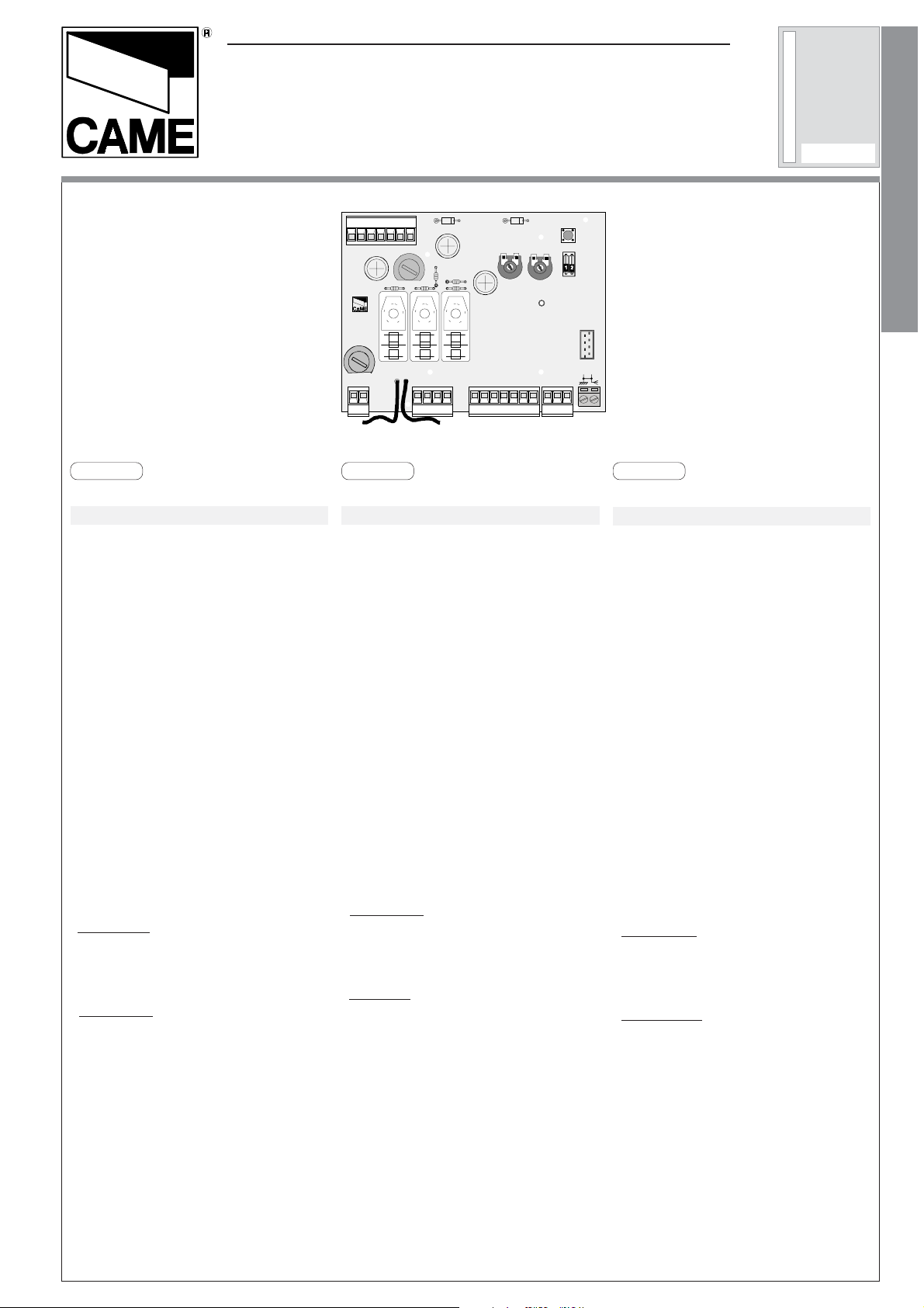
QUADRO COMANDO
ZC5
L1 L2
ENGLISH
UVWE1011
GENERAL CHARACTERISTICS
12 3 C14FFAFC
DESCRIPTION
The ZC5 electronic board is suitable for
controlling 230V single-phase automation
devices with power up to 500W.
The board is inserted and fastened to the
ABS (S4339 or S4340) container with IP54
protection level, which includes an air recycling inlet and transformer (see page
16).
The board requires 230V (AC) on terminal blocks L1 and L2, and is protected by
a 5A fuse, whilst the low voltage (24V)
command accessories are protected by a
1A fuse.
The accessories’ overall power (24V)
should not exceed 20W.
ITALIANO—ENGLISH—ESPAÑOL
ESPAÑOL
CARACTERISTICAS GENERALES
DESCRIPCIÓN
La tarjeta electrónica ZC5 es adecuada
para accionar automatizaciones de 230V
monofásica con potencia de hasta 500W .
La tarjeta se monta y se fija en la caja de
ABS (S4339 o S4340) con clase de protección IP54, dotada de toma para la recirculación de aire y de transformador
(véase página 16).
La tarjeta se debe alimentar a 230V (a.c.)
en los bornes L1 y L2, y debe estar protegida en entrada con un fusible de 5A,
mientras que los accesorios a baja tensión (24V) están protegidos con fusible
de 1A.
La potencia total de los accesorios (24V)
no debe superar 20W .
SICUREZZA
Le fotocellule possono essere collega-
te e predisposte per:
-
Riapertura
in fase di chiusura (2-C1), le
fotocellule rilevando un ostacolo durante la fase di chiusura del cancello, provocano l'inversione di marcia fino alla
completa apertura;
-
Stop totale
(1-2), arresto del cancello
con l'esclusione del ciclo di chiusura
automatica, per riprendere il movimento del cancello, agire sulla pulsantiera o
sul radiocomando;
SAFETY
Photocells can be connected to abtain:
- Re-opening during closure (2-C1), if the
photocells identify an obstacle while the
gate is closing, they will reverse the direction of movement until the gate is completely open;
- Total stop (1-2), shutdown of gate movement without automatic closing, a pushbutton or radio remote control must be
actuated to resume movement.
SEGURIDAD
Las fotocélulas pueden estar conecta-
das y predispuestas para:
Reapertura
-
en la fase de cierre (2-C1),
las fotocélulas detectan un obstáculo
durante el cierre de la puerta, provocando la inversión de marcha hasta la
apertura completa;
-
Parada total
(1-2), parada de la puerta
excluyendo el posible ciclo de cierre
automático; para reactivar el movimiento es preciso actuar en el teclado
o en el mando a distancia.
Page 2

ALTRE FUNZIONI
-
Chiusura automatica.
re di chiusura automatica si autoalimenta a fine tempo lavoro apre. Il tempo
prefissato regolabile, è in ogni modo
subordinato dall'intervento di eventuali
accessori di sicurezza e si esclude dopo
un intervento di "stop" o in mancanza
d'energia elettrica;
-
"Uomo presente"
cancello mantenendo premuto il pulsante (esclude la funzione del radiocomando);
Il temporizzato-
. Funzionamento del
OTHER FUNCTIONS
- Automatic closing. The automatic closing timer is automatically activated at the
end of the opening cycle. The preset,
adjustable automatic closing time is automatically interrupted by the activation of
any safety system, and is deactivated after
a STOP command or in case of power
failure;
- "Operator present". Gate operates only
when the pushbutton is held down (the
radio remote control system is deactivated).
OTRAS FUNCIÓNES
-
Cierre automático
cierre automático se autoalimenta en
fin-de-tiempo carrera en fase de apertura. El tiempo prefijado regulable, sin
embargo, está subordinado a la intervención de posibles accesorios de seguridad y se excluye después de una
intervención de parada o en caso de
falta de energía eléctrica;
-
Función a "hombre presente"
cionamiento de la puerta manteniendo
pulsada la tecla (excluye la función del
mando a distancia).
. El temporizador de
. Fun-
Regolazioni
ITALIANO—ENGLISH—ESPAÑOL
- Tempo chiusura automatica;
- Tempo lavoro.
ATTENZIONE: prima di intervenire
all'interno dell'apparecchiatura,
togliere la tensione di linea
Adjustments
- Automatic closure time;
- Operating time.
IMPORTANT: Shut off the mains
power before servicing the inside
of the unit.
Regulaciones
- Tiempo de cierre automático;
- Tiempo trabajo.
ATENCION: antes de actuar dentro del aparado, quitar la tensión
de línea
-2-
Page 3
SCHEDA B ASE -
33
3
33
MOTHERBOARD
55
5
55
- TARJETA BASE
66
6
66
44
4
44
22
2
22
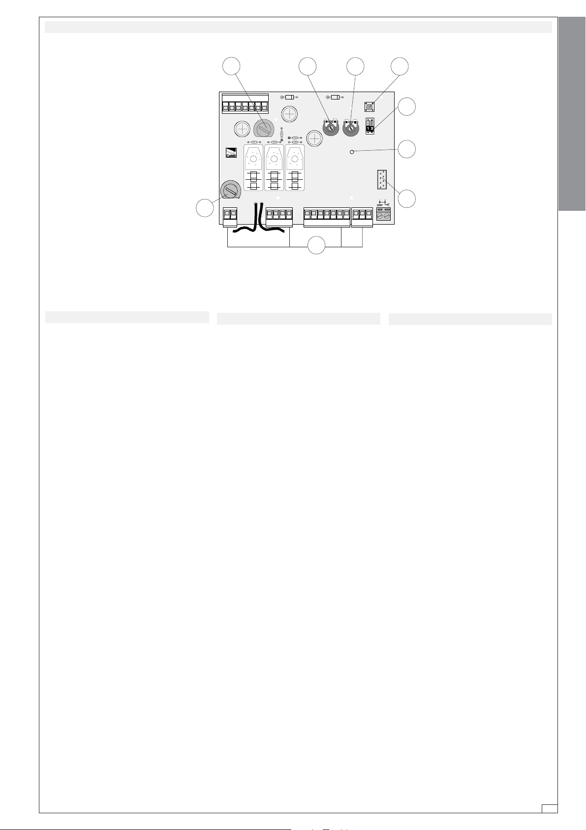
COMPONENTI PRINCIPALI
1 Morsettiere di collegamento
2 Fusibile di linea 5A
3 Fusibile accessori 1A
4 Pulsante memorizzazione codice
radio
5 Trimmer di regolazione tempo lavo-
ro
6 Trimmer di regolazione tempo di chiu-
sura automatica
7 Selettore funzioni a 2 dip (vedi pag. 9)
8 Innesto scheda radiofrequenza (vedi
tabella pagina 11)
9 LED segnalazione
PROG
TCATL
+-+-
QUADRO COMANDO
ZC5
L1 L2
MAIN COMPONENTES
1 Terminal block for external conections
UVWE1011
12 3 C14 F FA FC
11
1
11
2 Line fuse, 5A
3 Fuse on accessory power line, 1A
4 Radio-code save button
5 Trimmer for adjustment operating time
6 Trimmer for adjustment automatic clos-
ing
7 2-dip function switch (see pag. 9)
8 Socket AF radiofrequency board (see
table page 11)
9 Signal LED
77
7
77
99
9
99
88
8
88
PRINCIPALES COMPONENTES
1 Caja de bornes para las conexiónes
2 Fusible de línea 5A
3 Fusible accesorios 1A
4 Tecla de memorización del código
radio
5 Trimmer de regulación tiempo tra-
bajo
6 Trimmer de regulación tiempo cie-
rre automático
7 Selector de funciones con 2 dip (ve-
das pag. 9)
8 Conexión tarjeta radiofrecuencia AF
(vedas tabla pag. 11)
9 LED Kontrolleuchte zur Anzeige
ITALIANO—ENGLISH—ESPAÑOL
-3-
Page 4
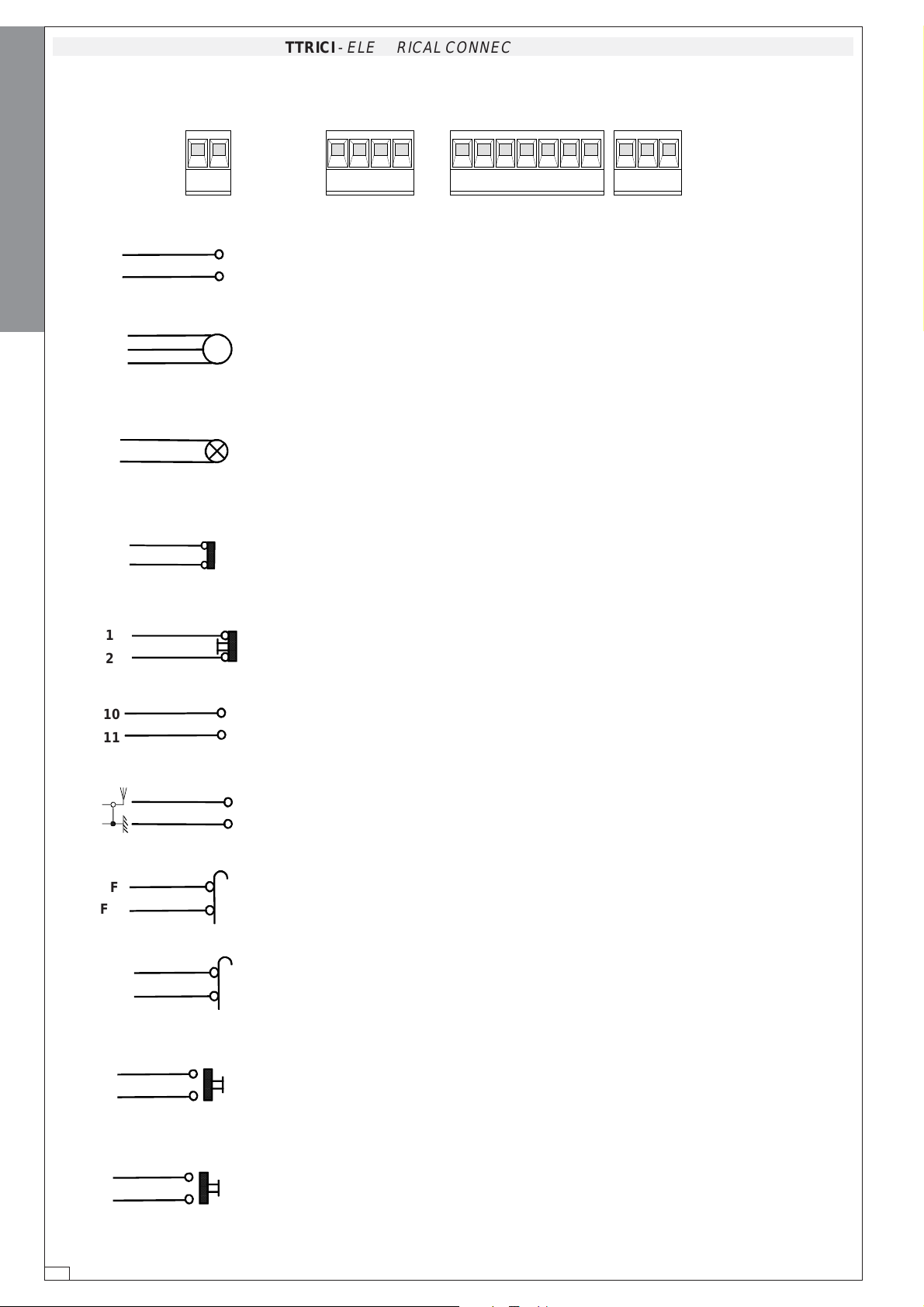
COLLEGAMENTI ELETTRICI -
ELECTRICAL CONNECTIONS -
CONEXIONES ELÉCTRICAS
ITALIANO—ENGLISH—ESPAÑOL
L1
L2
W
E
2
C1
U
W
V
L1 L2
UVWE
Alimentazione 230V (a.c.)
10
11
123 C14
F
FA FC
230V (a.c.) power input
Alimentación 230V (a.c.)
Motore monofase 230V (a.c.) max. 500W
Motor single-phase 230V (a.c.) max. 500W
Motor monofásico 230V (a.c.) max. 500W
Uscita 230V (a.c.) in movimento
(es. lampeggiatore - max. 25W)
230V (a.c.) output in motion (e.g. flashing light - max. 25W)
Salida de 230V (a.c.) en movimento (p.ej. conexión lámpara intermitente max. 25W)
Contatto (N.C.) di «riapertura durante la chiusura»
Contact (N.C.) for «re-opening during the closing»
Contacto (N.C.) para la «apertura en la fase de cierre»
1
2
10
11
F
FA
F
FC
Pulsante stop (N.C.)
Pushbutton stop (N.C.)
Pulsador de stop (N.C.)
Alimentazione accessori 24V (a.c.) max. 20W
24V (a.c.) Powering accessories max. 20W
Alimentación accesoios 24V (a.c.) max. 20W
Collegamento antenna
Antenna connection
Conexión antena
Finecorsa di apertura
Opening limit switch
Final de carrera de apertura
Finecorsa di chiusura
Closure limit switch
Final de carrera de cierre
2
3
Pulsante apre (N.O.)
Open button (N.O.)
Tecla de apertura (N.O.)
-4-
2
4
Pulsante chiude (N.O.)
(N.O.) Pushbutton-close
Pulsador de cierre (N.O.)
Page 5

SELEZIONI FUNZIONI -
TCATL
+-+-
FUNCTION SELECTIONS -
PROG
SELECCIÓNES FUNCIÓN
ON
OFF
21
ITALIANO—ENGLISH—ESPAÑOL
1 ON Chiusura automatica attivata;
(1 OFF - disattivata)
2 Non utilizzato
REGOLAZIONI -
1 ON Automatic closing enabled;
(1 OFF - disabled)
2 Not used
T.L.
ADJUSTMENTS -
T.C.A.
REGOLAZIONE TRIMMERS
REGOLAZIONE TRIMMERS
TRIMMERS ADJUSTME NT
TRIMMERS ADJUSTMENT
RÉGLAGE TR IMMERS
EINTELLUNG TRIMMERS
REGULACIÓN TRIMMERS
REGULACIÓN TRIMMERS
RÉGULACIÓNS
TCATL
+-+-
1 ON Cierre automático activado;
(1 OFF - desactivado)
2
PROG
No se utiliza
Trimmer T.L.
= Regolazione tempo lavoro
da un minimo di 15 secondi a un massimo
di 120 secondi.
Se il TL è regolato al minimo si attiva la
funzione “uomo presente”.
Trimmer T.C.A.
= Regolazione tempo di
chiusura automatica da un minimo di 0
secondi a un massimo di 120 secondi.
Trimmer T .L.
= Operation time setting for
a minimum of 15 seconds to a maximum
of 120 seconds.
If the TL is set to the minimum, the “dead
man” mode is activated.
Trimmer T.C.A.
= Adjusts automatic clos-
ing time (min.0”, max.120”)
T rimmer T.L.
= regulación tiempo de funcionamiento desde un mínimo de 15 segundos a un máximo de 120 segundos.
Si el TL se regula al mínimo se activa la
función “hombre muerto “.
Trimmer T.C.A.
= Régulación cierre auto-
mático (min. 0”, max. 120”).
-5-
Page 6

PROGRAMMAZIONE DEL RADIOCOMANDO /
PROGRAMACION DEL MANDO A DISTANCIA
PROGRAMMING THE REMOTE CONTROL
ITALIANO
PROCEDURA
A. inserire una scheda AF.
B. codificare il/i trasmettitore/i.
C. memorizzare la codifica sulla sche-
da base.
ITALIANO—ENGLISH—ESPAÑOL
A
INSERIMENTO SCHED A AF -
ENGLISH
PROCEDURE
A. insert an AF card.
B. encode transmitter/s.
C. store code in the motherboard.
AF BOARD INSERTION -
SCHEDA BASE
MOTHERBOARD
TARJETA BASE
ESPAÑOL
PROCEDIMIENTO
A. introducir una tarjeta AF.
B. codificar el/los transmisor/es.
C. memorizar la codificación en la tar-
jeta base.
MONT AJE DE LA TARJETA AF
C1 FFAFC
Frequenza / MHz
Frequency / MHz
Frecuencia / MHz
FM 26.995 AF130 TFM
FM 30.900 AF150 TFM
AM 26.995 AF26 TOP
AM 30.900 AF30 TOP
AM 433.92
Scheda rad i ofr eq u en za
Radiofrequency board
Tarjeta radiofrecuencia
AF43S / AF43SM TAM / TOP **
AF43SR ATOMO
SCHEDA "AF"
"AF" BOARD
TARJETA «AF»
T rasmettitore
Transmitter
T ransmisor
La schedina AF deve essere inserita OBBLIGA T ORIAMENTE in assenza di tensione, perché la scheda madre la riconosce solo quando viene alimentata
The AF board should ALWAYS be inserted when the power is off because the motherboard only recognises it when it is powered.
-6-
La tarjeta AF se debe montar OBLIGA T ORIAMENTE en caso de falta de corriente,
porque la tarjeta madre la reconoce sólo cuando está alimentada
Page 7

B
CODIFICA TRASMETTITORI -
TRANSMITTER ENCODING
- CODIFICACIÓN TRANSMISORES
PROCEDURA COMUNE
DI CODIFICA
1. segnare un codice (anche per archivio)
2. inserire jumper codifica J
3. memorizzarlo
4. disinserire jumper J
1.
P1
P2
TOP
1. assign a code (also on file)
2.connect encoding jumper J
3. register code
4. disconnect jumper J
QUARZATI
STANDARD ENCODING
codice/
- QUARTZ
PROCEDURE
code
/código
- CUARZO
PROCEDIMIENTO COMÚN DE
CODIFICACIÓN
1. marcar un código (también para el
archivo)
2. conectar un jumper codificación J
3. registrar el código
4. desconectar jumper J
OFF
ON
ITALIANO—ENGLISH—ESPAÑOL
3.
2.
J
premere in sequenza P1 o P2 per registrare il codice; al decimo
impulso un doppio suono confermerà l'avvenuta registrazione
Press P1 or P2 in sequence in order to register the code; at the tenth
pulse, a double beep will confirm that registration has occurred
oprimir repetidamente P1 ó P2 para registrar el código; con el
décimo impulso un doble sonido señalará que el registro se ha
efectuado.
4.
P1=OFF
P2=ON
J
-7-
Page 8

T262M - T302M
ITALIANO—ENGLISH—ESPAÑOL
P1 P2
fig. A
P1=CH1
P2=CH2
J
J
La prima codifica deve essere effettuata mantenendo i jumper posizionati per i
canali 1 e 2 come da fig. A; per eventuali e successive impostazioni su canali
diversi vedi fig. B
The first encoding operation must be carried out whilst keeping the jumpers
positioned for channels 1 and 2 as per fig. A; see fig. B for any subsequent
settings on different channels.
La primera codificación tiene que efectuarse manteniendo los jumper conectados para los canales 1 y 2 como se ilustra en la fig. A; para planteamientos
posteriores en canales distintos ver la fig. B
fig. B
P1=CH1 - P2=CH3
P1=CH1 - P2=CH4
T264M - T304M
P1=CH3 - P2=CH2
P1=CH3 - P2=CH4
P1 P2
P3 P4
P1
P2
J
2° codice/
T2622M - T3022M
1° codice/
code
code
/código
/código
P1=CH1
P2=CH2
P3=CH1
P4=CH2
OFF
ON
P1 P2
P3 P4
P1=CH1 - P2=CH2
P3=CH3 - P4=CH4
J
-8-
Page 9

B
CODIFICA TRASMETTITORI -
vedi foglio istruzioni inserito nella confezione
ver hoja de instrucciones adjunta en el embalaje
impostare il codice sul dip-switch C e il canale su D (P1=CH1 e
P1 P2
D
P2=CH2, impostazione di default)
set the code to dip-switch C and channel to D (P1=CH1 and
P2=CH2, default setting)
plantear el código en el dip-switch C y el canal en D (P1=CH1 y
1 2 3 4
P2=CH2, planteamiento por defecto)
TRANSMITTER ENCODING
- CODIFICACIÓN TRANSMISORES
ATOMO
AT01 - AT02 - AT04
della scheda AF43SR
see instruction sheet inside the pack of
AF43SR circuit card
de la tarjeta AF43SR
TOP
T432M - T312M
ITALIANO—ENGLISH—ESPAÑOL
P1 P2
P3 P4
1 2 3 4 5 6 7 8 9 10
P1=CH1
P2=CH2
P3=CH3
P4=CH4
1 2 3 4 5 6 7 8 9 10
TAM
C
T434M - T314M
impostare solo il codice
set code only
plantear sólo el código
C
P1
P2
1 2 3 4 1 2 3 4 1 2 3 41 2 3 4
CH1 CH2 CH3
1 2 3 4 1 2 3 4 1 2 3 4 1 2 3 4
CH1 CH2 CH3
T432S / T432SA / T434MA
CH4
CH4
vedi istruzioni su confezione
see instructions on pack
ver instrucciones en el embalaje
TFM
T432
T434
T438
vedi foglio istruzioni inserito nella
confezione
see instruction sheet inside the pack
ver hoja de instrucciones adjunta en el
embalaje
T132
T134
T138
T152
T154
T158
-9-
Page 10

C
MEMORIZZAZIONE CODICE -
CODE STORA GE
- MEMORIZACIÓN CÓDIGO
Tenere premuto il tasto "PROG" sulla
scheda base, il led di segnalazione lam
peggia (vedi fig.1), con un tasto del tra
smettitore si invia il codice, il led rimarrà
acceso a segnalare l'avvenuta
memorizzazione (fig.2).
N.B.: Se in seguito si vuol cambiare codice, basta ripetere la sequenza descritta.
ITALIANO—ENGLISH—ESPAÑOL
Fig./Abb.1
Keep the "PROG" key pressed on the base
card, the signal LED will flash (see fig.1),
and with a key on the transmitter the code
is sent, the LED will remain lit to signal the
successful saving of the code (figure 2).
N.B. If you wish to change the code on your
transmitters in the future, simply repeat the
procedure described above.
LED intermittente
Flashing LED
LED intermitente
Mantener oprimida la tecla "PROG" en la
tarjeta base, el led de señalización parpadea (mirar fig.1), con una tecla del
transmisor se envía el código, el led
permanece encendido para indicar que
el almacenamendo se ha efectuado
(fig.2).
Nota: Si posteriormente se quisiera cambiar el código de los propios transmisores, sólo hay que repetir la secuencia
descrita.
Fig./Abb.2
PROG
TCATL
+-+-
Scheda radiofrequenza AF
AF radiofrequency board
Tarjeta radiofrecuencia AF
E
101112 3 C1
PROG
TCATL
+-+-
4 FFAFC
LED acceso
LED encendido
Lit LED
-10-
Page 11

LIMITATORE DI COPPIA MOTORE /
MOTOR TORQUE LIMITER
/ LIMITADOR DE PAR MOTOR
Per variare la coppia motrice, spostare
il faston indicato (con filo di colore nero)
su una delle 4 posizioni; 1 min. - 4 max
1234
PROG
TCATL
+-+-
QUADRO COMANDO
ZC5
L1 L2 U V W E 10 11 1 2 3 C14 F FA FC
T
o vary the motor torque, move the indicated faston to one of the four positions:
1=min, 4=max
S4339
L1T L2T CT 0 12 24
Para variar el par motor, desplazar el
faston indicado hasta una de las 4 posiciones; 1 mín. - 4 máx.
ITALIANO—ENGLISH—ESPAÑOL
1234
L2T
L1T L2 T CT 0 12 24
1
234
0
12
24
L1T
S4340
L1T
L2T
1
234
02412
PROG
TCATL
+-+-
QUADRO COMANDO
ZC5
UVWE1011
L1 L2
12 3 C14 F FA FC
-11-
Page 12

DICHIARAZIONE DEL FABBRICANTE
Allegata alla documentazione tecnica (l’originale della Dichiarazione è disponibile a richiesta)
I Rappresentanti della
CAME Cancelli Automatici S.p.A.
via Martiri della Libertà, 15
31030Dosson di Casier - T re viso - ITALYtel
(+39) 0422 4940 - fax (+39) 0422 4941
internet: www.came.it - e-mail: info@came.it
Dichiarano sotto la propria responsabilità che i/il prodotto/i denominato/i ...
ZC5
… sono conformi alle disposizioni legislative Nazionali che traspongono le seguenti Direttive
Comunitarie (dove specificatamente applicabili):
ITALIANO—ENGLISH—ESPAÑOL
DIRETTIVA MACCHINE 98/37/CE
DIRETTIVA BASSA TENSIONE 73/23/CEE - 93/68/CEE
DIRETTIVA COMPATIBILITÀ ELETTROMAGNETICA 89/336/CEE - 92/31/CEE
DIRETTIVA R&TTE 1999/5/CE
Ai sensi dell’Allegato II B della Direttiva Macchine 98/37/CE
Documentazioni tecniche specifiche dei prodotti sono disponibili a richiesta!
Data della presente dichiarazione 07/12/2001
Inoltre, dichiara che il/i prodotto/i, oggetto della presente dichiarazione, sono costruiti nel rispetto
delle seguenti principali norme armonizzate:
EN 292 PARTE 1ª E 2ª SICUREZZA DEL MACCHINARIO.
EN 12453 CHIUSURE INDUSTRIALI, COMMERCIALI …
EN 12445 CHIUSURE INDUSTRIALI, COMMERCIALI …
EN 60335 - 1 SICUREZZA NEGLI APPARECCHI AD USO DOMESTICO ...
EN 60204 - 1 SICUREZZA DEL MACCHINARIO.
EN 50081 - 1 E 2COMPATIBILITÀ ELETTROMAGNETICA.
EN 50082 - 1 E 2COMPATIBILITÀ ELETTROMAGNETICA.
AVVERTENZA IMPORTANTE!
È vietato mettere in servizio il/i prodotto/i, oggetto della presente dichiarazione, prima del
completamento e/o incorporamento, in totale conformità alle disposizioni della Direttiva
Macchine 98/37/CE
Firma dei Rappresentanti
RESPONSABILE TECNICO
Sig. Gianni Michielan
PRESIDENTE
Sig. Paolo Menuzzo
MANUFACTURER’S DECLARATION
Enclosed with the technical documentation (the original copy of the Declaration is available on request)
The representatives of
CAME Cancelli Automatici S.p.A.
via Martiri della Libertà, 15
31030 Dosson di Casier - T re viso - ITALY
tel (+39) 0422 4940 - fax (+39) 0422 4941
internet: www.came.it - e-mail: info@came.it
Hereby declare, under their own respons ibility , that the product/s called ...
As per Enclosure II B of Machinery Directive 98/37/CE
ZC5
… comply with the Italian National Legal Provisions that transpose the
following Community Directives (where specifically applicable):
MACHINERY DIRECTIVE 98/37/CE
LOW VOLTAGE DIRECTIVE 73/23/EEC - 93/68/EEC
LECTROMAGNETIC COMPATIBILITY DIRECTIVE 89/336/EEC - 92/31/EEC
R&TTE DIRECTIVE 1999/5/CE
Specific technical documentation on the products is available on request!
DECLARACION DEL FABRICANTE
Adjunta a la documentación técnica (el original de la Declaración está disponible previa petición)
Los Representantes de la compañía
CAME Cancelli Automatici S.p.A.
via Martiri della Libertà, 15
31030 Dosson di Casier - T re viso - ITALY
tel (+39) 0422 4940 - fax (+39) 0422 4941
internet: www.came.it - e-mail: info@came.it
Declaran bajo su responsabilidad que el/los producto/s denominado/s ...
ZC5
… cumplen con las disposiciones legislativas nacionales que trasponen las siguientes
Directivas Comunitarias (donde específicamente aplicables):
DIRECTIVA DE MÁQUINAS 98/37/CE
DIRECTIVA DE BAJA TENSIÓN 73/23/CEE - 93/68/CEE
DIRECTIVA DE COMPATIBILIDAD ELECTROMAGNÉTICA 89/336/CEE - 92/31/CEE
DIRECTIVA R&TTE 1999/5/CE
De conformidad con el Anexo II B de la Directiva de Máquinas 98/37/CE
Documentación técnica específica de los productos está disponible previa petición
Date of the present declaration 07/12/2001
Also, they furthermore represent and warrant that the product/s that are the subject of the present
Declaration are manufactured in the respect of the following main harmonized provisions:
EN 292 PART 1 AND 2MACHINERY SAFETY.
EN 12453 INDUSTRIAL, COMMERCIAL AND OTHER CLOSING MECHANISMS.
EN 12445 INDUSTRIAL, COMMERCIAL AND OTHER CLOSING MECHANISMS.
EN 60335 - 1 SAFETY IN APPARATUSES FOR HOME USE.
EN 60204 - 1 MACHINERY SAFETY.
EN 50081 - 1 AND 2ELECTROMAGNETIC COMPATIBILITY.
EN 50082 - 1 AND 2ELECTROMAGNETIC COMPATIBILITY.
IMPORTANT CAUTION!
It is forbidden to market/use product/s that are the subject of this declaration before completing and/
or incorporating them in total compliance with the provisions of Machinery Directive 98/37/CE
Signatures of the Representatives
TECHNICAL MANAGER
Mr. Gianni Michielan
Fecha de la presente declaración 07/12/2001
Los productos objeto de esta declaración están fabricados respetando las siguientes normas
armonizadas:
EN 292 PAR TE 1ª Y 2ª SEGURIDAD DE LAS MÁQUINAS.
EN 12453 CIERRES INDUSTRIALES, COMERCIALES …
EN 12445 CIERRES INDUSTRIALES, COMERCIALES …
EN 60335 - 1 SEGURIDAD DE LOS APARATOS PARA USO DOMÉSTICO...
EN 60204 - 1 SEGURIDAD DE LAS MÁQUINAS.
EN 50081 - 1 E 2COMPATIBILIDAD ELECTROMAGNÉTICA.
EN 50082 - 1 E 2COMPATIBILIDAD ELECTROMAGNÉTICA.
AVVERTENZA IMPORTANTE!
Está prohibido hacer uso de el/los producto/s, objeto de la presente declaración antes de completarlo/
s y/o incorporarlo/s en total conformidad a las disposiciones de la Directiva de Máquinas 98/37/CE.
Firma de los Representantes
RESPONSABLE TÉCNICO
Sr. Gianni Michielan
MANAGING DIRECTOR
Mr. Paolo Menuzzo
PRESIDENTE
Sr. Paolo Menuzzo
Tutti i dati sono stati controllati con la massima cura. Non ci
assumiamo comunque alcuna responsabilità per eventuali
errori od omissioni.
ASSISTENZA TECNICA
NUMERO VERDE
SISTEMA QUALITÀ
CERTIFICATO
800 295830
EB
W
www.came.it
E-MAIL
CANCELLI AUTOMATICI
info@came.it
CAME CANCELLI AUTOMATICI S.P.A.
DOSSON DI CASIER (TREVISO)
(+39) 0422 4940 (+39) 0422 4941
All data checked with the maximum care. However, no liability is
accepted for any error or omission.
CAME LOMBARDIA S.R.L.______COLOGNO M. (MI)
(+39) 02 26708293 (+39) 02 25490288
CAME SUD S.R.L. ___________________NAPOLI
(+39) 081 7524455 (+39) 081 7529109
CAME (AMERICA) L.L.C.____________MIAMI (FL)
(+1) 305 5930227 (+1) 305 5939823
CAME AUTOMATISMOS S.A__________MADRID
(+34) 091 5285009 (+34) 091 4685442
CAME BELGIUM_NV-SA______________LESSINES
(+32) 068 333014 (+32) 068 338019
Todos los datos se han controlado con la máxima atención.
No obstante no nos responsabilizamos de los posibles
errores u omisiones.
CAME FRANCE S.A.____NANTERRE CEDEX (PARIS)
(+33) 01 46130505 (+33) 01 46130500
CAME GMBH________KORNTAL BEI (STUTTGART)
(+49) 07 11839590 (+49) 07 118395925
CAME GMBH____________SEEFELD BEI (BERLIN)
(+49) 03 33988390 (+49) 03 339885508
CAME PL SP.ZO.O______________WARSZAWA
(+48) 022 8365076 (+48) 022 8369920
CAME UNITED KINGDOM LTD___NOTTINGHAM
(+44) 01159 210430 (+44) 01159 210431
 Loading...