

Page 1
SERIE Z |
Z
SERIES
/ SÉRIE Z |
BAUREIHE
Z |
SERIE Z
Documentazione
Tecnica
SCHEDA COMANDO
CONTROL BOARD
CARTE DE COMMANDE
STEUERPLATINE
TARJETA DE MANDO
ZC3C
S92
rev. 0.3
01/2006
©
CAME
CANCELLI
AUTOMATICI
319S92
ITALIANO
CARATTERISTICHE GENERALI
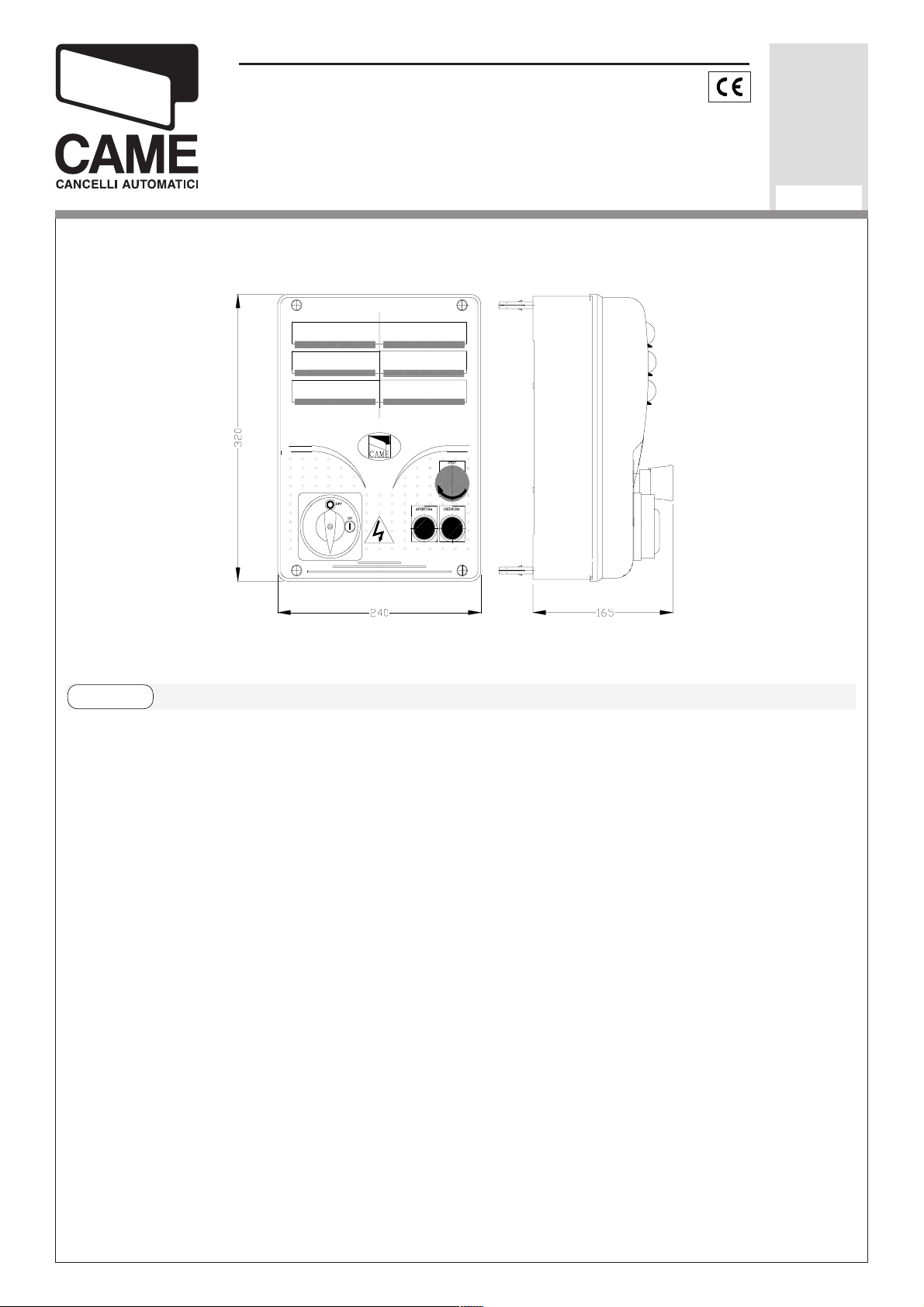
Descrizione quadro
Il quadro elettrico ZC3C è adatto al
comando di una automazione per portoni
industriali scorrevoli della serie C e F3000,
alimentati a 230V con potenza fino a
600W, frequenza 50÷60 Hz.
Progettato e costruito interamente
dalla CAME S.p.A., risponde alle
vigenti norme UNI 8612. Contenitore in
ABS con grado di
protezione IP54, dotato di
presa per il riciclo d’aria,
blocco di sicurezza,
trasformatore.
Il circuito va alimentato con tensione di
230V (a.c.) nei morsetti L1- L2 e
protetto in ingresso con due fusibili da
5A, mentre i dispositivi di comando a
bassa tensione sono protetti con
fusibile da 1A.
La potenza complessiva degli accessori (24V) non deve superare i 20W.
pulsanti apre, chiude, stop
e completo di
Page 2

Il quadro include la funzione di spunto
motore fermo (portone chiuso, aperto o
manovra. Questa funzione si attiva in
fase di inizio apertura e chiusura del
portone.
Sicurezza
Le fotocellule possono essere collegate
e predisposte per:
-
Riapertura
le fotocellule rilevando un’ostacolo
durante la fase di chiusura del portone,
provocano l'inversione di marcia fino
alla completa apertura;
-
Richiusura
dip n° 8 in OFF - 9 in OFF), le
in fase di chiusura (2-C1),
in fase di apertura (2-CX,
dopo un comando di stop totale),
impedisce qualsiasi movimento se i
dispositivi di sicurezza (es.fotocellule)
rilevano un ostacolo;
-
Funzione del test di sicurezza
comando di apertura e chiusura delle
ante, la centralina verifica l'efficenza
delle fotocellule (vedi pag.18).
Accessori collegabili
-
Lampada ciclo
la zona di manovra, rimane accesa dal
momento in cui le ante iniziano l’apertu-
ra fino alla completa chiusura
. Lampada che illumina
. Ad ogni
fotocellule rilevando un’ostacolo
durante la fase di apertura del portone,
provocano l’inversione di marcia fino
alla completa chiusura;
-
Stop parziale,
in movimento con conseguente predisposizione alla chiusura automatica
(2-CX, dip n°8 in OFF - 9 in ON);
-
Stop totale
con l'esclusione del ciclo di chiusura
automatica, per riprendere il movimento, agire sulla pulsantiera o sul radiocomando.
Nota: Se un contatto di sicurezza
arresto del cancello se
(1-2), arresto del cancello
(compreso il tempo di chiusura automa-
tica). Nel caso non venga inserita la
chiusura automatica, rimane accesa
solo durante il movimento E-EX, dip
n°16 in OFF - 17 in ON);
-
Lampada di cortesia.
illumina la zona di manovra, dopo un
comando di apertura rimane accesa
per un tempo fisso di 5 minuti e 30
secondi (E-EX, dip n°16 in ON - 17 in
OFF);
-
Lampada spia portone aperto
pada che segnala la posizione di
apertura del portone scorrevole, si
Lampada che
. Lam-
normalmente chiuso (2-C1, 2-CX, 1-2)
si apre, viene segnalato dal lampeggio
del LED di segnalazione (pag.12 - n°8);
-
Rilevazione di presenza ostacolo
-2-
. A
spegne quando il portone attiva il
Page 3

finecorsa chiude.
-apre-stop-chiude-stop con pulsante e/
Altre funzioni
-
Chiusura automatica.
Il
temporizzatore di chiusura automatica
si autoalimenta a finecorsa apre. Il
tempo prefissato regolabile, è in ogni
modo subordinato dall'intervento di
eventuali accessori di sicurezza e si
esclude dopo un intervento di "stop" o
in mancanza d'energia elettrica.
-
Apertura parziale
. Apertura del
cancello per passaggio pedonale,
viene attivata collegandosi ai morsetti
2-3P ed è regolabile mediante trimmer
AP.PARZ.. Con questa funzione, la
o trasmettitore;
-apre-chiude con pulsante e/o trasmettitore;
-solo apre con trasmettitore.
Regolazioni
- Tempo lavoro;
- Tempo chiusura automatica;
- Tempo di apertura parziale.
chiusura automatica varia nel seguente
modo:
1) Dip 12 in ON: dopo un'apertura
parziale, il tempo di chiusura automatica è indipendente dalla regolazione del
trimmer TCA e dalla posizione del dip
n°1, ed è fisso a 8 secondi.
2) Dip 12 in OFF: dopo un'apertura
parziale, il tempo di chiusura automatica (se inserita) è regolabile tramite
trimmer TCA;
-
"Uomo presente"
. Funzionamento del
cancello mantenendo premuto il
pulsante (esclude la funzione del
radiocomando);
-
Prelampeggio
. Dopo un comando di
apertura o di chiusura, il lampeggiatore
collegato su W-E, lampeggia per 5
secondi prima di iniziare la manovra.
-Tipo di comando
:
Attenzione! Prima di intervenire
all’interno dell’apparecchiatura, togliere la tensione di linea.
-3-
Page 4

ENGLISH
GENERAL CHARACTERISTICS
Description of control panel
The ZC3C electric panel is suitable for
controlling the automation of series C and
F3000, 230V sliding industrial gates, with
up to 600W power and 50-60 Hz frequency.
Wholly designed and built by CAME
S.p.A., it meets UNI 8612 regulations in
force. ABS Case with an IP54 protective
level, with air recycling inlet, safety block,
open, close and stop pushbuttons
and transformer.
The circuit requires 230V (a.c.) at terminal blocks L1- L2 and the inlet is pro-
photocells identify an obstacle while
the gate is opening, they will reverse
the direction of movement until the gate
is completely close;
- Partial stop,
shutdown of moving gate,
with activation of an automatic closing
cycle (2-CX, dip n°8 OFF - 9 ON);
-
Total stop
(1-2), shutdown of gate
movement without automatic closing; a
pushbutton or radio remote control
must be actuated to resume
movement.
N.B
: If an NC safety contact (2-C1, 2-
CX, 1-2) is opened, the LED (pag.12
tected with two 5A fuses, whilst the low
voltage command devices are protected by a 1A fuse.
The accessories’ total wattage (24V)
must not exceed 20W.
The panel includes a manoeuvre pickup function. This function is activated
during the initial phase of the gate’s
opening and closing.
Safety
Photocells can be connected to obtain:
Re-opening
-
during closure (2-C1), if
the photocells identify an obstacle
-n°8) will flash to indicate this fact;
-
Obstacle presence detection.
When
the motor is stopped (gate is closed,
open or half-open after an emergency
stop command), the transmitter and the
control pushbutton will be deactivated if
an obstacle is detected by one of the
safety devices (for example, the
photocells);
-
Safety test function.
The control unit
will now check the safety system every
time an opening or closing command is
given (see p.18).
while the gate is closing, they will
reverse the direction of movement until
the gate is completely open;
-
Re-closing
during opening (2-CX, see
dip n°8 to OFF - 9 to OFF), if the
-4-
Accessories which can be
connected to this unit
-
Cycle lamp.
The lamp which lights the
manoeuvring zone: it remains lit from
the moment the doors begin to open
Page 5

until they are completely closed
ment of the TCA trimmer and of the po-
(including the time required for the
automatic closure). In case automatic
closure is not enabled, the lamp
remains lit only during movement (EEX, dip n°16 OFF - 17 ON);
-
Courtesy Light.
the manoeuvring zone; after an opening command, the light remains on for a
fixed time of 5 minutes and 30 seconds
(E-EX, dip n°16 ON - 17 OFF);
-
Open gate pilot lamp
indicates the sliding gate’s open
position and turns off when the gate
activates the closing end-stop.
A light that illuminates
. It is a light that
sition of Dip 1; it is set at 8 seconds.
2) Dip 12 set to OFF: after a partial
opening, the time for automatic closing
is adjustable only if Dip 1 is set to ON.
-
"Operator present".
only when the pushbutton is held down
(the radio remote control system is
deactivated);
-
Pre-flashing
closing command, the flasher
connected to the W-E flashes for 5
seconds before beginning the procedure;
. After an opening or
-Type of command
Gate operates
:
Other functions
-
Automatic closing.
closing timer is automatically activated
at the end of the opening cycle. The
preset, adjustable automatic closing
time is automatically interrupted by the
activation of any safety system, and is
deactivated after a STOP command or
in case of power failure;
-
Partial opening.
allow for foot traffic; activated by
connecting to terminals 2-3P and
adjusted with the AP-PARZ. trimmer.
The automatic
Opening of the gate to
-Open-stop-close-stop by button and
transmitter;
-Open-close by button and transmitter;
-Open only by transmitter.
Adjiustments
- Operating time;
- Automatic closure time;
- Partial opening time.
With this function, the automatic
closing can vary in the following way:
1) Dip 12 set to ON: after a partial
opening, the time for automatic closing
functions independently of the adjust-
Caution! Disconnect the unit
from the main power lines before
carrying out any operation inside the
unit.
-5-
Page 6

FRANÇAIS
CARACTÉRISTIQUES GÉNÉRALES
Description armoire de commande
L’armoire électrique ZC3C sert à
commander l’automation des grandes
portes coulissantes d’usine de la série
C et F3000, alimentées à 230V avec
puissance jusqu’à 600W, fréquence
50÷60 Hz.
Conçu et construit entièrement par
CAME S.p.A., il est conforme aux
normes NFP 25-362 en vigueur. Boîtier
en ABS avec degré de protection IP54,
équipé d’une prise pour le recyclage de
l’air blocage de sécurité, boutons d’ou-
verture, de fermeture et d’arrêt
et d’un transformateur.
Le circuit doit être alimenté avec une
tension de 230V (c.a.) aux bornes L1L2 et doit être protégé à l’entrée par
deux fusibles de 5A, tandis que les
dispositifs de commande à basse
tension sont protégés par un fusible de
1A.
La puissance totale des accessoires
(24V) ne doit pas dépasser 20W.
L’armoire de commande est prévu avec
la fonction de courant supérieur de
démarrage. Cette fonction s’active en
début d’ouverture et de fermeture de la
porte.
jusqu'à l'ouverture complète si elles
relèvent un obstacle durant la phase de
fermeture du portail;
-
Réfermeture
en phase de ouverture
(2-CX, dip n°8 OFF - 9 OFF), les
cellules photoélectriques provoquent
l'inversion de marche jusqu'à fermeture
complète si elles relèvent un obstacle
durant la phase de ouverture du portail;
-
Stop partiel,
arrêt du portail, si en
mouvement, et conséquente programmation pour la fermeture automatique
(2-CX, dip n°8 OFF - 9 ON);
-
Stop total
(1-2), arrêt du portail et
désactivation d’un éventuel cycle de
fermeture automatique; pour activer de
nouveau le mouvement, il faut agir sur
les boutons-poussoirs ou sur la
radiocommande.
Remarque
: Le voyant (pag.12, LED
n°8) de signalisation qui clignote
indique qu'un contact de sécurité
normalment fermé (2-C1, 2-CX, 1-2)
s'ouvre.
-
Détection de présence d'obstacle.
Quand le moteur est arrêté (portail
fermé, ouvert ou semi-ouvert, cette
position est obtenue avec une
commande de stop total), annule toute
Sécurité
Il est possible de brancher des
photocellules et de les programmer
pour:
-
Réouverture
en phase de fermeture
(2-C1), les cellules photoélectriques
provoquent l'inversion de marche
-6-
fonction de l’émetteur ou du boutonpoussoir en cas d’obstacle détecté par
les dispositifs de sécurité (ex.
Photocellules) ;
-
Fonction du test de securité
. Cela
permet au boîtier de vérifier le bon
fonctionnement des despositifs de
securité aprés chaque commande
d'ouverture ou de fermeture (voir
Page 7

pag.18);
Accessoires pouvant être branchés
AP.PARZ.. Avec cette fonction, la
fermeture automatique varie de la
-
Lampe cycle
zone de manoeuvre: elle reste allumée
à partir du moment ou les portes
commencent l’ouverture jusqu’à la
fermeture complète (y compris le
temps de fermeture automatique). Si
elle n’est pas insérée la fermeture
automatique reste allumée seulement
durant le mouvement (E-EX, dip n°16
OFF - 17 ON);
-
Lampe passage
zone de manoeuvre, après une commande d’ouverture elle reste allumée
pour une durée fixe de 5 minutes et 30
secondes (E-EX, dip n°16 ON - 17
OFF);
. Ampoule qui illumine la
. Lampe qui illumine la
façon suivante :
1) Dip 12 sur ON : après une ouverture
partielle, le temps de fermeture automatique est indépendant du réglage du
trimmer TCA et de la position du dip 1,
et est fixe à 8 secondes.
2) Dip 12 sur OFF : après une ouverture partielle, le temps de fermeture
automatique est réglable seulement si
le dip 1 est positionné sur ON;
“Homme mort”
portail en maintenant appuyé le
bouton-poussoir (exclut la fonction de
la radiocommande);
-
Pré-clignotement
commande d'ouverture ou de
. Fonctionnement du
. Après une
-
Lampe porte ouverte
signale la position d’ouverture de la
porte coulissante, elle s’éteint quand la
porte active l’interrupteur de fin de
course fermeture.
Autres functions
-
Fermeture automatique.
risateur de fermeture automatique est
autoalimenté à la fin du temps de la
course en ouverture. Le temps réglable
est programmé, cependant, il est
subordonné à l’intervention d’éventuels
accessoires de sécurité et il est exclu
après une intervention de “stop” ou en
cas de coupure de courant;
. Lampe qui
Le tempo-
fermeture, le clignotant branché sur WE, clignote pendant 5 secondes avant
de commencer la manoeuvre;
-
Type de commande
-ouvre-stop-ferme-stop pour bouton et
émetteur;
-ouvre-ferme pour bouton et émetteur;
-seulement ouverture pour émetteur.
Réglages
- Temps de fonctionnement;
- Temps de fermeture automatique;
- Temps d’ouverture partielle.
:
-
Ouverture partielle
grille pour le passage pour piétons, elle
est enclenchée en la reliant aux bornes
2-3P et est réglable par le trimmer
. Ouverture de la
Attention! Avant d’intervenir à
l’intérieur de l’appareillage, couper la
tension de ligne.
-7-
Page 8

DEUTSCH
ALLGEMEINE MERKMALE
Beschreibung des Steuergeräts
Die elektrische Schalttafel ZC3C ist geeignet für die Steuerung automatischer
Schiebetore der Serie C und F3000,
Versorgung 230V und Leistung bis
600W, Frequenz 50÷60 Hz.
Sie ist von der CAME S.p.A. entworfen
und erstellt und entspricht den geltenden Richtlinien UNI 8612. Der Kasten ist
in ABS, Schutzgrad IP54 mit Anschluß
für die Luftrückführung Sicherheitssperre
und Tasten für Öffnen, Schließen und
und Transformator.
Stop
Die Versorgung des Stromkreises erfolgt mit 230V (Wechselstrom) über die
Klemmen L1-L2 und ist am Eintritt
Dip-Schalter 8OFF - 9OFF), die
Lichtschranken ermitteln ein Hindernis
während des Öffnen vom Tor und
lösen die Umkehr der Laufrichtung vom
Tor aus, bis dieses wieder vollständig
geschlossen ist;
T
eilstop
-
, Stillstand des Tores während
des Torlaufs, mit darauffolgender
automatischer Torschließung (2-CX,
Dip-Schalter 8OFF - 9ON);
Totalstop
-
(1-2), sofortiger Stillstand
des Tores mit Ausschluß eventueller
Schließautomatik: Fortsetzung des
Torlaufs über Drucktaster- bzw. Funksendersteuerung;
Hinweis
: Wenn sich ein normalerweise
durch 2 Sicherungen von 5A geschützt.
Die Steuervorrichtungen mit Unterspannung sind mit einer 1A-Sicherung
ausgestattet.
Die Gesamtleistung des Zubehörs
(24V) darf 20W nicht überschreiten.
Die Schalttafel umfaßt die Anlassfunktion. Diese Funktion startet bei
Beginn des Schließ- oder Öffnungsvorganges des Tores.
Sicherheitsvorrichtungen
Die Lichtschranken können für
folgende Funktionen angeschlossen
bzw. vorbereitet werden:
Wiederöffnen
-
beim Schließen (2-C1),
geschlossener (NC) Sicherheitskontakt
(2-C1, 2-CX, 1-2) öffnet, wird dies
durch Blinken der Kontrolleuchte (S.12
- n°8) angezeigt.
Ermittlung eventuell vorhandener
-
Hindernisse
. Bei stillstehendem Motor
(Tor geschlossen, geöffnet oder durch
eine Totalstop-Steuerung halb geöffnet)
wird bei durch die Sicherheitsvorrichtungen (z.B.: Lichtschranken)
erfaßtem Hindernis jede Sender- oder
Drucktasterfunktion annulliert;
Sicherheitstest-Funktion.
-
Dadurch
besteht die Möglichkeit, die
Leistungsfähigkeit der Sicherheitsvorrichtungen nach jeder Öffnungs-und
die Lichtschranken ermitteln ein
Hindernis während des schließens vom
Tor und lösen die Umkehr der
Laufrichtung vom Tor aus, bis dieses
wieder vollständig geöffnet ist;
Wiederschließen
-
-8-
beim Öffnen (2-CX,
Schließsteuerung zu überprüfen (siehe
Seite 18).
Anschließbares Zubehör
Betriebszyklus-Anzeigeleuchte.
-
Das
Licht, das den Torbereich beleuchtet,
Page 9

bleibt vom Beginn des Öffnens bis zum
folgendermaßen:
vollständigen Schließen der Torflügel
eingeschaltet (einschließlich Wartezeit
für automatisches Schließen). Wenn
das automatische Schließen nicht zugeschaltet ist, bleibt das Licht nur
während der Torbewegung
eingeschaltet (E-EX, Dip-Schalter
16OFF - 17ON);
- Torbeleuchtung
zum Öffnen des Tors gegeben worden
ist, bleibt das Licht, das den Manöverbereich am Tor beleuchtet, für eine
vorgegebene Zeit von 5 Minuten und
30 Sekunden eingeschaltet (E-EX, DipSchalter 16ON - 17OFF);
Kontrollampe bei geöffnetem Tor
-
. Nachdem der Befehl
. Die
1)Dip 12 auf ON: Nach einem
teilweisen Öffnen erfolgt das Schließen
des Tor unabhängig von der Einstellung
des Trimmer TCA und der Stellung des
Dip-Switch 1, und zwar nach einer
vorgegebenen Zeit von 8 Sekunden;
2)Dip 12 auf OFF: Nach einem
teilweisen Öffnen kann die Zeit für das
automatische Schließen nur dann
eingestellt werden, wenn der DipSwitch 1 auf ON steht;
“Bedienung vom Steuerpult”.
Torbetrieb durch Drucktasterbetätigung
(Funkfernsteuerung ausgeschlossen);
- Vorblinken
Öffnen oder Schließen gegeben
. Nachdem der Befehl zum
Kontrollampe zeigt an, daß das Tor
geöffnet ist; sie erlischt wenn das Tor
den Endanschlag des
Schließvorganges erreicht hat.
Andere Wahlfunktionen
Schließautomatik
automatik-Zeischalter speist sich beim
Öffnen am Ende der Torlaufzeit selbst .
Die voreingestellte Zeit ist auf jeden
Fall immer dem Eingriff eventueller
Sicherheitsvorrichtungen untergeordnet
und schließt sich nach einem “Stop”Eingriff bzw. bei Stromausfall selbst
aus;
Teilweises Öffnung.
-
. Der Schließ-
Das Öffnen des
worden ist, blinkt das Blinklicht, das an
W-E angeschlossen ist, zunächst 5
Sekunden, bevor das Manöver beginnt;
-Befehlsarten
-Öffnen-Stop-Schließen-Stop für
Druckknopf und Sender;
-Öffnen-Schließen für Druckknopf und
Sender;
-nur Öffnen für Sender.
Einstellungen
- Laufzeit;
- Zeit für das automatische Schließen;
- Zeit für das teilweise Öffnen.
:
Tors für das Durchlassen von
Fußgängern wird durch Anschluß an
die Klemmen 2-3P aktiviert und kann
über den Trimmer AP.PARZ. eingestellt
werden. Wenn diese Funktion aktiviert
ist, variiert das automatische Schließen
Achtung! Das Gerät vor
Eingriffen im inneren spannungsfrei
schalten.
-9-
Page 10

ESPANOL
CARACTERISTICAS GENERALES
Descripción cuadro de mando
El cuadro eléctrico ZC3C es idóneo
para el control de una automatización
para puertas industriales de corredera
de la serie C y F3000, alimentados a
230V, con potencia de hasta 600W,
frecuencia 50÷60 Hz.
Diseñado y fabricado completamente por
CAME S.p.A., responde a las normas
UNI 8612 vigentes. Caja de ABS con grado de protección IP54, con toma para
recirculación bloqueo de seguridad,
botones abrir, cerrar, parada
de aire y transformador.
El circuito se alimenta con tensión de
230V (c.a.) en los bornes L1- L2 y está
protegido en entrada con dos fusibles
de 5A, mientras que los dispositivos de
baja tensión están protegidos con
fusible de 1A.
La potencia total de los accesorios
(24V) no debe superar los 20W.
El cuadro incluye la función de punto
de arranque. Dicha función se activa
durante el comienzo de apertura y
cierre de la puerta.
marcha hasta la apertura completa;
-
Recierre
en la fase de apertura (2CX, dip 8OFF - 9OFF), las fotocélulas
detectan un obstáculo durante la
apertura de la puerta, provocando la
inversión de marcha hasta el cierre
completo;
-
Parada parcial,
parada de la puerta si
se encuentra en movimiento con la
consiguiente predisposición al cierre
automático (2-CX, dip 8OFF - 9ON);
-
Parada total
(1-2), parada de la puerta
excluyendo el posible ciclo de cierre
automático, para reactivar el
movimiento es preciso actuar en el
teclado o en el mando a distancia.
Nota
: La apertura de un contacto de
seguridad normalmente cerrado (2-C1,
2-CX, 1-2) es señalada por medio del
destello del LED de señalización
(pág.12 -n°8).
-
Detección de presencia obstáculo
.
Con el motor parado (puerta cerrada,
abierta o en posición semi-abierta
obtenida a través de un comando de
stop total), anula cualquier función del
Seguridad
Las fotocélulas pueden estar con
ectadas y predispuestas para:
-
Reapertura
en la fase de cierre (2C1), las fotocélulas detectan un
obstáculo durante el cierre de la
puerta, provocando la inversión de
-10-
transmisor o del botón en caso de
obstáculo detectado por los
dispositivos de seguridad (por ejemplo:
fotocélulas).
-
Función de las pruebas de seguridad.
Permite a la central comprobar la
eficiencia en los dispositivos de
seguridad después de cada comando
de apertura y cierre (véase pág.18).
Page 11

Accesorios conectables
-
Lámpara ciclo.
Lámpara que alumbra
AP.PARZ. Con dicha función el cierre
automático se modifica de la siguiente
manera:
la zona de maniobra: se queda
encendida a partir del momento en que
las hojas empiezan la apertura hasta el
cierre completo (incluyendo el tiempo
de cierre automático). Si no se habilita
el cierre automático, el cierre
permanece encendido sólo durante el
movimiento (E-EX, dip 16OFF - 17ON)
- Luz de cortesía
la zona de maniobra; tras un mando de
apertura permanece encendida por 5
minutos y 30 segundos (E-EX, dip
16ON - 17OFF);
-
Indicador luminoso de puerta abierta
Lámpara que indica que la puerta de
. Lámpara que ilumina
1) Dip 12 en ON: luego de una apertura
parcial, el tiempo de cierre automático
es independiente de la regulación del
trimmer TCA y de la posición del dip 1
y queda fijo en 8 segundos;
2) Dip 12 en OFF: luego de una apertu-
ra parcial, el tiempo de cierre
automático puede ser regulado sólo si
el dip 1 está colocado en ON;
-
"Hombre presente"
de la puerta manteniendo pulsada la
tecla (excluye la función del mando a
distancia);
.
-
Intermitencia
de apertura o cierre, la lámpara
. Después de un mando
. Funcionamiento
corredera está abierta, se apaga
cuando la puerta activa el final de
carrera de cierre.
Otras funciones
-
Cierre automático
cierre automático se autoalimenta en
fin-de-tiempo carrera en fase de
apertura. El tiempo prefijado regulable,
sin embargo, está subordinado a la
intervención de posibles accesorios de
seguridad y se excluye después de
una intervención de parada o en caso
de falta de energía eléctrica;
-
Apertura parcial.
. El temporizador de
La apertura de la
intermitente conectada en W-E,
parpadea por 5 segundos antes de
comenzar la maniobra;
-Tipo de mando
-abrir-stop-cerrar-stop para botón y
transmisor;
-abrir-cerrar para botón y transmisor;
-sólo apertura para transmisor.
Regulaciones
- Tiempo de trabajo;
- Tiempo de cierre automático;
- Tiempo de apertura parcial.
:
verja para el paso peatonal, se activa
conectando los bornes 2-3P y puede
ser regulada por medio del trimmer
¡Atención! Antes de actuar den-
tro del aparato, quitar la tensión de
línea.
-11-
Page 12

SCHEDA BASE -
F
.
3
A
L
-
3
CH1C
C
N
2
3
D
F
V
E
W
U
E1
EX
VS
L1T
CT
L2T
13
MOTHERBOARD
- CARTE BASE -
Nota: collegare i fili neri che fuoriescono
dalla scheda sui connettori del condensatore.
GRUNDPLATINE
- TARJETA BASE
3
4
12
VS
L1T
234
1
L2T
01224
NB: connect the black wires coming out of
the board to the condenser’s connectors.
Note: connecter les fils noirs qui sortent
de la carte sur les connecteurs du
condensateur.
8
CH1 CH2
CLOSE OPEN
LOSE OPE
AF
1 2 3 4 5 6 7 8 9 10 11 12
1 2 3 4 5 6 7 8 9 10 11 1
H2
04 05 06 07 08
04 05 06 07 08
9
V4 V5
V1 V2 V
V1 V2 V3 V4 V5
10
11
18
0
24 12
CONTROL BOARD
CONTROL BOAR
FUSE
USE
315mA
ACCESS.
ACCESS
FUSE
USE
1A
LINE FUSE 5A
L1
L2
15m
INE FUSE 5A
2
5 6 7
+ OPER.TIME -
+ OPER.TIME -
ON
1 2 3 4 5 6 7 8 9 10
CONTROL BOARD
CONTROL BOARD
ZC3
ZC
10 11 TS 1 2 3 3P 4 5 7
+ AUT.CL. - + PAR.OP. -
+ AUT.CL. -+ PAR.OP.
ON
11 12 13 14 15 16 17 18 19 20
2 C1 CX FC FA F B1 B2
+ E D
1
Hinweis: Die schwarzen Kabel, die von der
Karte wegführen, an die Verbinder am
Kondensator anschließen.
Nota: conectar los hilos negros que
salen de la tarjeta en los conectores del
condensador.
15
16
14
ITALIANO
COMPONENTI PRINCIPALI
1 Morsettiere di collegamento
2 Fusibili di linea 5A
3 Fusibile accessori 1A
4 LED segnalazione tensione presente a
24V
5 Trimmer di regolazione tempo lavoro
6 Trimmer di regolazione tempo di chiu-
sura automatica
7 Trimmer di regolazione apertura par-
ziale
8 LED segnalazione
9 Pulsanti memorizzazione codice
10 Selettore funzioni (vedi pag.20)
11 Innesto scheda radiofrequenza (vedi
tabella)
12 Trasformatore
13 Limitatore di coppia motore (vedi pagi-
na 16)
14 Blocco di sicurezza
15 pulsante STOP
16 pulsante CHIUSURA
17 pulsante APERTURA
18 Fusibile scheda 630 mA
17
ENGLISH
1 Terminal block for external conections
MAIN COMPONENTES
2 Line fuses, 5A
3 Fuse on accessory power line, 1A
4 24V power-supply signalling LED
5 Trimmer for adjustment operating time
6 Trimmer for adjustment automatic closing
7 Trimmer for adjustment partial opening
8 Signal LED
9 Radio-code save buttons
10 20-Dip function switch (see pag.20)
11 Socket AF radiofrequency board (see
table)
12 transformer
13 Motor torque limiter (see page 16)
14 Blocage de sécurité
15 bouton ARRET
16 bouton FERMETURE
17 bouton OUVERTURE
18 Fuse Control board 630 mA
-12-
Page 13

FRANÇAIS
PRINCIPAUX COMPOSANTS
1 Plaque à bornes de connexion
2 Fusibles de ligne 5A
3 Fusible accessoires 1A
4 LED de signalisation alimentation à 24V
5 Trimmer de réglage temps de fonctionnement
6 Trimmer de réglage fermeture automatique
7 Trimmer de réglage temps ouverture partielle
8 LED de signalisation
9 Boutons-poussoir mémorisation code radio
10 Selecteur de fonctions à 20 interrupteurs à positions multiples (voir pag.20)
11 Branchement carte radiofréquence AF (voir tableau)
12 Transformateur
13 Limiteur de couple moteur (voir pag.16)
14 Blocage de sécurité
15 Bouton ARRET
16 Bouton FERMETURE
17 Bouton OUVERTURE
18 Fiche fusibile 630 mA
DEUTSCH
1 AnschlußKlemmenleiste
2 Hauptsicherungen 5A
3 Zubehör-Sicherung 1A
4 LED Kontrolleuchte für Stromversorgung mit 24V
5 Trimmer zur Einstellung Laufzeit
6 Trimmer zur Einstellung der Schließautomatik
7 Trimmer zur Einstellung Teilöffnung
8 LED Kontrolleuchte zur Anzeige
9 Knöpfe zum Abspeicher der Radiocodes
10 Wählschalter für Funktionen mit 20 Dip (sehen S.20)
11 Steckanschluß Funkfrequenze-Platine AF (sehen Tabelle)
12 Transformator
13 Drehmomentbegrenzer des Motors (sehen Seite 16)
14 Sicherheitssperre
15 STOP-Taste
16 SCHLIESSEN-Taste
17 ÖFFNEN-Taste
18 Schemelz Zettel 630 mA
ESPANOL
HAUPTKOMPONENTEN
PRINCIPALES COMPONENTES
1 Caja de bornes para las conexiónes
2 Fusibles de línea 5A
3 Fusible accesorios 1A
4 Indicador luminoso de alimentación de 24V
5 Trimmer de regulación tiempo trabajo
6 Trimmer de regulación tiempo cierre automático
7 Trimmer de regulación tiempo apertura parcial
8 LED de señal
9 Teclas de memorización del código radio
10 Selector de funciones con 20 dip (vedas pág.20)
11 Conexión tarjeta radiofrecuencia AF (vedas tabla)
12 Transformador
13 Limitador de par motor (vedas pág.16)
14 Bloqueo de seguridad
15 Botón PARADA
16 Botón CIERRE
17 Botón APERTURAù
18 Fusibile ficha 630 mA
-13-
Page 14

COLLEGAMENTI ELETTRICI -
ELEKRISCHE ANSCHLÜSSE -
ELECTRICAL CONNECTIONS -
CONEXIONES ELÉCTRICAS
BRANCHEMENTS ÉLECTRIQUES
L1 L2 U V W E EX 10 11 TS 1 2 3 3P 4 5 7 2 C1 CX FCFA F B1B2
Alimentazione 230V (a.c.)
L1
L2
U
W
V
W
E
230V (a.c.) power input
Alimentation 230V (c.a.)
Stromversorgung 230V (Wechselstrom)
Alimentación 230V (a.c.)
Motore monofase 230V (a.c.) max. 600 W
230V (a.c.) single-phase motor max. 600 W
Moteur monophasé 230V (c.a.) max.600 W
M
Einphasenmotor 230V (Wechselstrom) max. 600 W
Motor monofásico 230V (a.c.) max. 600 W
Uscita 230V (a.c.) in movimento
(es.lampeggiatore - max. 25W)
230V (a.c.) output in motion
(e.g. flashing light - max. 25W)
Sortie 230V (c.a.) en mouvement
(ex. branchement clignotant - max. 25W)
Ausgang 230V (Wechselstrom) in Bewegung
(z.B. Blinker-Anschluß - max. 25W)
Salida de 230V (a.c.) en movimento
(p.ej. conexión lámpara intermitente - max. 25W)
UVWEEX
E
EX
10
11
-14-
Uscita 230V (a.c.)
lampada ciclo - max. 60W
16 OFF - 17 ON
ON
Output 230V (a.c.)
max.60W - cycle lamp
Sortie 230V (c.a.)
lampe cycle - max. 60W
Ausgang 230V (Wechselstrom)
Betriebszyklus-Anzeigeleuchte
- max.60W
Salida de 230V (a.c.)
lámpara ciclo - max.60W
Uscita 230V (a.c.)
lampada cortesia - max. 60W
Output 230V (a.c.)
max.60W - courtesy lamp
Sortie 230V (c.a.)
lampe d’éclairage - max. 60W
Ausgang 230V (Wechselstrom)
Torbeleuchtung
- max.60W
16 ON - 17 OFF
Salida de 230V (a.c.)
lámpara cortesía - max.60W
Alimentazione accessori 24V (a.c.) max. 20W
24V (a.c.)Powering accessories (max 20W)
Alimentation accessoires 24V (c.a.) max. 20W
Zubehörspeisung 24V (Wechselstrom) max. 20W
Alimentación accesoios 24V (a.c.) max. 20W
11 13 14 15 16 17
12
UVWEEX
ON
11 13 14 15 16 17
12
18 19 20
18 19 20
Page 15

10
5
1
2
2
3
2
3P
Lampada spia (24V-3W max.) "portone aperto"
(24V-3W max.) "gate-opened" signal lamp
Lampe-témoin (24V-3W max.) "portail ouverture"
Signallampe (24V-3W max.) "Tor Öffnen"
Lámpara indicadora (24V-3W max.) "puerta abierta"
Pulsante stop (N.C.)
Pushbutton stop (N.C.)
Bouton-poussoir arrêt (N.F.)
Stop-Taste (Ruhekontakt)
Pulsador de stop (N.C.)
Pulsante di apertura (N.O.)
Pushbutton opens (N.O.)
Bouton-poussoir de ouverture (N.O.)
Taste (Arbeitskontakt) für Öffnen
Pulsador de apertura (N.O.)
Pulsante per apertura parziale (N.O.)
Button (N.O.) for partial opening
Bouton-poussoir (N.O.) pour ouverture partial
Taste (Arbeitskontakt) für TeilÖffnung
Pulsador (N.O.) para apertura parcial
2
4
2
7
2
CX
Pulsante di chiusura (N.O.)
Pushbutton closes (N.O.)
Bouton-poussoir de ouverture (N.O.)
Taste (Arbeitskontakt) für Schließen
Pulsador de cierre (N.O.)
Contatto radio e/o pulsante per comando (vedi dip p.20)
Contact radio and/or button for control (see dip pag.20)
Contact radio et/ou poussoir pour commande (dip p.20)
Funkkontakt und/oder Taste Steuerart (sehen Dip S.20)
Contacto radio y/o pulsador para mando (vedas dip p.20)
Contatto (N.C.) di «richiusura durante la apertura»
Contact (N.C.) for «re-closing during the opening»
Contact (N.F.) de «réfermeture pendant la ouverture»
Kontakt (Ruhekontakt) «erneutes Schließen beim Öffnen»
Contacto (N.C.) para la «recierre
en la fase de apertura»
Contatto (N.C.) di «stop parziale»
ON
8 OFF - 9 OFF
1 34567
2
Contact (N.C.) for «partial stop»
Contact (N.F.) de «stop partiel»
ON
Kontakt (Ruhekontakt) «Teilstop»
Contacto (N.C.) para la «parada parcial»
1 34567
2
8910
8910
2
C1
8 OFF - 9 ON
Contatto (N.C.) di «riapertura durante la chiusura»
Contact (N.C.) for «re-opening during the closing»
Contact (N.F.) de «réouverture pendant la fermeture»
Kontakt (Ruhekontakt) «Wiederöffnen beim Schliessen»
Contacto (N.C.) para la «apertura en la fase de cierre»
-15-
Page 16

F
FUSE
A
.
A
FUSE
VS
L1T
CT
L2T
F
.
3
A
L
3
CH1C
C
N
2
3
D
F
V
E
W
U
E1
EX
VS
L1T
CT
L2T
FC
F
FA
B1
B2
Collegamento finecorsa chiude
Connection limit switch closes
Connexion fin de course fermeture
Anschluß Endschallter Schließen
Conexión fin de carrera cierre
Collegamento finecorsa apertura
Connection limit switch opens
Connexion fin de course ouverture
Anschluß Endschallter Öffnen
Conexión fin de carrera apertura
Uscita contatto (N.O.) Portata contatto: 5A - 24V d.c.
Contact output (N.O.) Resistive load: 5A -
24V d.c.
Sortie contact (N.O.) Portée contact: 5A - 24V c.c.
Ausgang Arbeitskontakt Stromfestigkeit: 5A-24V Gleichstrom
Salida contacto (N.O.) Carga resistiva: 5A - 24V d.c.
Collegamento antenna
Antenna connection
Connexion antenne
Antennenanschluß
Conexión antena
LIMITATORE DI COPPIA MOTORE /
Per variare la
coppia motrice, spostare il
faston indicato
(con filo di
colore nero) su
una delle 4
posizioni; 1
min. - 4 max
MOTOR TORQUE LIMITER
DREHMOMENTBEGRENZER DES MOTORS
To vary the
motor torque,
move the
indicated faston
to one of the
four positions:
1=min, 4=max
Pour varier le
couple du
moteur,
déplacer le
connecteur
indiqué sur
l'une des 4
positions; 1
min. - 4 max.
VS
L1T
234
1
01224
L2T
0
24 12
/ LIMITEUR DE COUPLE MOTEUR
/LIMITADOR DE PAR MOTOR
Zur Änderung
des MotorDrehmoments
den angegebenen Faston auf
eine der 4
Stellungen
positionieren: 1
Para variar el
par motor,
desplazar el
faston
indicado hasta
una de las 4
posiciones; 1
mín. - 4 máx.
min. - 4 max.
VS
L1T
234
1
01224
L2T
+AUT.CL.-+PAR.OP.-
+AUT.CL.-+PAR.OP.-
+OPER.TIME-
0
24 12
CONTROLBOARD
CONTROLBOAR
FUSE
USE
315mA
15m
ACCESS.
ACCESS
FUSE
USE
1A
LINEFUSE5A
INEFUSE5A
L1 L2
+OPER.TIME-
ON
12345678910
CONTROLBOARD
CONTROLBOARD
ZC3
ZC
1011TS1233P457
ON
11121314151617181920
2C1CXFCFAFB1B2
+ED
LOSE OPE
CLOSE OPEN
CH1 CH2
H2
V4V5
0405060708
0405060708
V1V2V
V1V2V3V4V5
123456789101112
12345678910111
AF
FUSE
315mA
ACCESS.
CCESS
FUSE
1A
315m
-16-
Page 17

ISTRUZIONI MONTAGGIO CERNIERE -
INSTRUCTIONS MONTAGE CHARNIÈRES S4340
MONTAGEANWEISUNGEN SCHARNIERE S4340 -
1
Assemblare le cerniere a pressione
Assemble the hinges by pressure
Assembler les charnières à pression
Setzen Sie die Druckscharniere zusammen.
Ensamblar las bisagras a presión
15 mm~
scorrono per ruotare
they must slide in order to turn
elles glissent pour tourner
laufen zum Drehen
deslizan para girar
ASSEMBLY INSTRUCTIONS S4340 HINGES
INSTRUCCIONES MONTAJE BISAGRAS S4340
!!
2
Inserire le cerniere nella scatola (sul lato
destro o sinistro a scelta) e fermarle con le
viti e le rondelle in dotazione
Insert the hinges (on the right or left side,
according to choice) and secure using the
screws and washers supplied
Placer les charnières (du côté droit ou
gauche au choix) et les fixer avec les vis et
les rondelles fournies de série
Setzen Sie die Scharniere ein (je nach
Wunsch auf der rechten oder linken Seite)
und befestigen Sie sie mit den mitgelieferten
Schrauben und Unterlegscheiben
Introducir las bisagras (en el lado izquierdo o
derecho, a placer) y fijarlas con los tornillos
y las arandelas suministradas a tal efecto
295 mm
215 mm
3
Posizionare e fissare la scatola del
quadro
Position and secure the control
panel housing
Placer et fixer la boîte de l'armoire
Plazieren Sie das Gehäuse der
Schalttafel und befestigen Sie es.
Colocar y sujetar la caja del cuadro
Inserire a scatto il coperchio sulle cerniere,
4
chiuderlo e fissarlo con le viti in dotazione
Snap the cover onto the hinges and secure
using the screws supplied.
Assembler par encliquetage le couvercle sur
les charnières et fixer le couvercle avec les vis
fournies de série
Lassen Sie den Deckel in den Scharnieren
einrasten und befestigen Sie ihn mit den
mitgelieferten Schrauben.
Introducir la tapa en las bisagras hasta oír un
chasquido y fijar la tapa con los tornillos
suministrados a tal efecto.
-17-
Page 18

TEST FUNZIONAMENTO FOTOCELLULE -
TEST FONCTIONNEMENT PHOTOCELLULES
TEST FÜR DAS FUNKTIONIEREN DER LICHTSCHRANKEN -
PHOTOCELL FUNCTION TEST
TEST FUNCIONAMIENTO FOTOCELULAS
FIG. 1
ABB. 1
-
+
«DOC»
ITALIANO
-
+
C.
N.O.
N.C.
10 11 TS 1 2 3 3P 4 5 7
Consente alla centralina di verificare l'efficienza dei dispositivi di
sicurezza (fotocellule) dopo ogni
comando di apertura o di chiusura.
Un'eventuale anomalia delle
fotocellule è identificata con un
lampeggio del led sul quadro comando, di conseguenza annulla
qualsiasi funzione del
radiocomando e dei pulsanti.
Collegamento elettrico per il funzionamento del test di sicurezza.
I trasmettitori e i ricevitori delle
fotocellule devono essere collegati
come illustrati nelle fig.1 e fig.2.
- selezionare il dip 13 in ON per
attivare il funzionamento del test.
IMPORTANTE: Quando si esegue la
funzione test di sicurezza, VERIFICARE che NON CI SIANO PONTI tra
i contatti 2-CX, 2-C1 e, se non
utilizzati, escluderli tramite dip 7 e 8.
FIG. 2
ABB. 2
«DIR»
ENGLISH
Rx
10 2 TX C NC
-
+
10 11 TS 1 2 3 3P 4 5 7
FUSIBILE 200mA
TX 2
TX 2
-
It allows the gearcase to check the
efficiency of the safety devices
(photoelectric cells) after each
command to open or close. Any
anomaly of the photoelectric cells is
identified with a flash of the LED on the
control panel; therefore all functions of
the remote control and buttons are
cancelled.
Electrical connection for safety-test
functioning.
The transmitters and the receivers of
the photoelectric cells must be
connected as illustrated in figs.1 and 2.
- move dip switch 13 to ON, which will
activate the test function.
IMPORTANT: When the safety test
function is performed, check that there
are no jumpers between contacts 2CX, 2-C1 and, if not being used,
exclude them using dip switches 7 and
8.
-18-
Page 19

FRANÇAIS
DEUTSCH
Il permet à la centrale de vérifier
l'efficacité des dispositifs de
sécurité (photocellules) après
chaque commande d'ouverture ou
de fermeture. Un led qui clignote sur
le tableau de commande indique une
anomalie éventuelle des
photocellules, ce qui annule toute
fonction de la radiocommande et
des boutons.
Branchement électrique pour le
fonctionnement du test de sécurité.
Les émetteurs et les récepteurs des
photocellules doivent être branchés
comme indiqué sur les fig. 1 et 2.
- mettre le dip-switch 13 sur ON
pour activer le fonctionnement du
test.
IMPORTANT: En effectuant la
fonction test de sécurité, VERIFIER
s'il Y A DES PONTS entre les
contacts 2-CX, 2-C1 et les exclure à
l'aide des microinterrupteurs 7 et 8,
s'ils ne sont pas utilisés.
Erlaubt der Steuerung, die
Funktionstüchtigkeit der
Sicherheitsvorrichtungen
(Lichtschranken) nach jedem Befehl
zum Öffnen oder Schließen zu
kontrollieren. Eine Störung an den
Lichtschranken wird durch Blinken vom
LED an der Steuertafel angezeigt und
setzt Fernbedienung und Tasten
vorübergehend außer Betrieb.
Stromanschluß für den Sicherheitstest.
Die Sender und Empfänger der
Lichtschranken müssen wie auf Abb. 1
und 2 dargestellt angeschlossen
werden.
BITTE BEACHTEN: Wenn der
Sicherheitstest durchgeführt wird, muß
SICHERGESTELLT werden, daß die
Kontakte 2-CX und 2-C1 nicht.
- Dip-Switch 13 zur Aktivierung der
Sicherheitstest-Funktion auf ON
stellen.
ÜBERBRÜCKT sind. Wenn die
Kontakte nicht benützt werden, müssen
sie mit den Dip-Schaltern 7 und 8
ausgeschlossen werden.
ESPANOL
Permite que la central verifique la eficiencia de los dispositivos de seguridad
(fotocélulas) después de cada mando de apertura o de cierre. Una posible
irregularidad de las fotocélulas es identificada con un parpadeo del
indicador luminoso en el cuadro de mandos, anulando toda función de los
radiomandos y de los botones.
Conexión eléctrica para el funcionamiento del ensayo de seguridad.
Los transmisores y receptores de las fotocélulas se deben conectar tal
como muestran las figuras 1 y 2.
- seleccionar el dip 13 en ON para activar el funcionamiento de la prueba.
IMPORTANTE: cuando se ejecuta la función de ensayo de seguridad,
CONTROLE que NO HAYA PUENTES DE CONEXIÓN entre los contactos 2CX, 2-C1 y, si no se los utiliza, desconéctelos con los dips 7 y 8.
-19-
Page 20

FUSE
6
L
-
+
-
-
AF
C
D
ZC3
CH1
C
C
N
2
5
8
C
D
FUSE
V
E
W
U
E1
EX
VS
L1T
CT
L2T
SELEZIONI FUNZIONI -
FUNKTIONSWAHL
SELECTION OF FUNCTIONS
- SÉLECTION FONCTIONS
- SELECCIÓN DE LAS FUNCIONES
DIP-SWITCHES (1-10)
+ AUT.CL.
PAR.OP.
+ AUT.CL. - + PAR.OP. -
+ OPER.TIME
0
24 12
CONTROL BOARD
ONTROL BOAR
FUSE
315mA
30mA
ACCESS.
ACCESS.
FUSE
1A
+ OPER.TIME -
ON
1 2 3 4 5 6 7 8 9 10
ON
11 12 13 14 15 16 17 18 19 20
CLOSE OPEN
LOSE OPE
CH1 CH2
H2
4 05 06 07 0
04 05 06 07 08
V1 V2 V3 V4 V
V1 V2 V3 V4 V5
1 2 3 4 5 6 7 8 9 10 11 12
1 2 3 4 5 6 7 8 9 10 11 1
AF
+ E D
ONON
ON
ONON
OFFOFF
OFF
OFFOFF
ON
L1 L2
45678910
213
LINE FUSE 5A
INE FUSE 5A
CONTROL BOARD
ONTROL BOAR
ZC3
10 11 TS 1 2 3 3P 4 5 7
2 C1 CX FC FA F B1 B2
ITALIANO
1 ON Chiusura automatica attivata; (1OFF - disattivata)
2 ON "Apre-stop-chiude-stop" con pulsante (2-7) e radiocomando (scheda AF
inserita) attivata;
2 OFF "Apre-chiude" con pulsante (2-7) e radiocomando (scheda AF inserita) attiv.;
3 ON "Sola apertura" con radiocomando (scheda AF inserita) attivata; (3OFF -
disattivata)
4 OFF "Uomo presente" (esclude il funzionamento del radiocomando) disattivata;
(4ON - attivata)
5 ON Prelampeggio attivato; (5OFF - disattivato)
6 ON Rilevazione di presenza ostacolo attivata; (6OFF - disattivata)
7 OFF Riapertura in fase di chiusura attivata; con dispositivo di sicurezza collegato
ai morsetti 2-C1, (se non viene utilizzato il dispositivo, selezionare il dip in ON)
8 OFF-9 OFF Richiusura in fase di apertura attivata; con dispositivo di sicurezza
collegato ai morsetti 2-CX;
8 OFF-9 ON Stop parziale attivata; con dispositivo di sicurezza collegato ai
morsetti 2-CX;
se non vengono utilizzati i dispositivi su 2-CX, posizionare il dip 8 in ON)
(
10OFF Stop totale attivato con pulsante collegato ai morsetti 1-2, (se non viene
utilizzato, selezionare il dip in ON)
-20-
Page 21

ENGLISH
1 ON Automatic closure activated; (1OFF-deactivated)
2 ON "Open-stop-close-stop" with button (2-7) and radio control (AF board inserted)
activated;
2 OFF "Open-close" with button (2-7) and radio control (AF board inserted) activated;
3 ON "Only opening" with radio control (AF board inserted) activated; (3OFF-
deactivated)
4 OFF "Operator present" (radio remote control is deactivated when function is
selected) deactivated; (4ON -activated)
5 ON Pre-flashing activated; (5OFF-deactivated)
6 ON Obstacle detection device activated; (6OFF-deactivated)
7 OFF Re-opening in closing phase activated; connect the safety device on terminals
2-C1, (if not used, set the dip-switch to ON)
8 OFF-9 OFF Re-closing activated; connect the safety device on terminals 2-CX,
8 OFF-9 ON Partial stop activated; connect the safety device on terminals 2-CX,
(if the devices on the 2-CX terminals are not used, set Dip 8 to ON)
10OFF Total stop activated; connect the safety device on terminals 1-2, (if not used,
set the dip-switch to ON)
FRANÇAIS
1 ON Fermeture automatique activée; (1OFF-désactivée)
2 ON "Ouvre-stop-ferme-stop" avec bouton (2-7) et commande-radio (carte AF
insérée) activée;
2 OFF "Ouvre-ferme" avec bouton (2-7) et commande-radio (carte AF insérée)
activée;
3 ON "Soulement ouverture" avec commande-radio (carte AF insérée) activée;
(3OFF-désactivée)
4 OFF "Homme mort" (exclut la fonction radiocommande) désactivée; (4ON-activée)
5 ON Preclignotement activée; (5OFF-désactivée)
6 ON Dispositif de détection d'obstacle activée; (6OFF-désactivée)
7 OFF Réouverture en phase de fermeture activée; relier le dispositif de sécuritè
aux bornes 2-C1; (s'il n'est pas utilisé, positionner l'interrupteur à positions
multiples sur ON)
8 OFF-9 OFF Réfermeture en phase de ouverture activée; relier le dispositif de
sécuritè aux bornes 2-CX;
8 OFF-9 ON Stop partiel activée; relier le dispositif de sécurite aux bornes 2-CX;
si les dispositifs sur 2-CX ne sont pas utilisés, positionner le dip 8 sur ON)
(
10OFF Stop total activée relier le dispositif de sécurite aux bornes 1-2, (s'il n'est pas
utilisé, positionner l'interrupteur à positions multiples sur ON)
-21-
Page 22

DEUTSCH
1 ON Schließautomatik aktiviert; (1OFF - deaktiviert)
2 ON "Öffnen-Stop-Schließen-Stop" mit Druckknopf (2-7) und Fernsteuerung (Karte
AF eingesteckt) aktiviert;
2 OFF "Öffnen-Schließen" mit Druckknopf (2-7) und Fernsteuerung (Karte AF
eingesteckt) aktiviert;
3 ON "nur Öffnen" mit Fernsteuerung (Karte AF eingesteckt) aktiviert; (3OFF -
deaktiviert)
4 OFF Bedienung vom "Steuerpult" (bei Wahl dieser Betriebsart wird die Funkfern-
steuerung ausgeschlossen) deaktiviert; (4ON - aktiviert)
5 ON Vorblinken aktiviert; (5OFF - deaktiviert)
6 ON Hindemisaufnahme aktiviert; (6OFF - deaktiviert)
7 OFF Wiederöffnen beim Schließen aktiviert; schließen Sie die
Sicherheitsvorrichtung an die Klemmen 2-C1 an, falls nicht verwendet,
schalten Sie den Dip auf ON;
8 OFF-9 OFF Funktion für erneutes Schließen während dem Öffnen aktiviert;
schließen Sie die Sicherheitsvorrichtung an die Klemmen 2-CX an
8 OFF-9 ON Teilstop aktiviert; schließen Sie die Sicherheitsvorrichtung an die
Klemmen 2-CX
(Wenn die Sicherungen nicht an die Klemmen 2-CX angeschlossen werden,
die Dip 8 auf ON stellen)
10OFF Totalstop aktiviert schließen Sie die Sicherheitsvorrichtung an die Klemmen
1-2 an, (falls nicht verwendet, schalten Sie den Dip auf ON)
ESPANOL
1 ON Cierre automático activado; (1OFF-desactivado)
2 ON "Abrir-stop-cerrar-stop" con botón (2-7) y radiocontrol (tarjeta AF conectada)
activado;
2 OFF "Abrir-cerrar" con botón (2-7) y radiocontrol (tarjeta AF conectada) activado;
3 ON "Solo apertura" con radiocontrol (tarjeta AF conectada) activado; (3OFF-
desactivado)
4 OFF "Hombre presente" (escluye la función del mando de radio) desactivado;
(4ON - activado)
5 ON Pre-intermitencia activado; (5OFF-desactivado)
6 ON Detección del presencia obstáculo activado; (6OFF-desactivado)
7 OFF Reapertura en la fase de cierre activado; conecte el dispositivo de seguridad
a los bornes 2-C1, (si no se utiliza, poner el dip en ON)
8 OFF-9 OFF Recierre durante la apertura (conecte el dispositivo de seguridad a
los bornes 2-CX) activado;
8 OFF-9 ON Parada parcial (conecte el dispositivo de seguridad a los bornes
2-CX) activado;
(si no utiliza los dispositivos en 2-CX, coloque el dip 8 en ON)
10OFF Parada total activado; conecte el dispositivo de seguridad a los bornes 1-2,
(si no se utiliza, poner el dip en ON)
-22-
Page 23

FUSE
6
L
-
+
-
-
C
D
ZC3
CH1
C
C
N
2
5
8
C
D
FUSE
V
E
W
U
E1
EX
VS
L1T
CT
L2T
DIP-SWITCHES (11-20)
+ AUT.CL. - + PAR.OP. -
+ AUT.CL.
PAR.OP.
+ OPER.TIME -
0
24 12
CONTROL BOARD
ONTROL BOAR
FUSE
315mA
ACCESS.
ACCESS.
30mA
FUSE
1A
+ OPER.TIME
ON
1 2 3 4 5 6 7 8 9 10
ON
11 12 13 14 15 16 17 18 19 20
CH1 CH2
CLOSE OPEN
LOSE OPE
H2
4 05 06 07 0
04 05 06 07 08
V1 V2 V3 V4 V5
V1 V2 V3 V4 V
1 2 3 4 5 6 7 8 9 10 11 12
1 2 3 4 5 6 7 8 9 10 11 1
+ E D
AF
18 19 20
ONON
ON
ONON
OFFOFF
OFF
OFFOFF
CONTROL BOARD
INE FUSE 5A
LINE FUSE 5A
L1 L2
ONTROL BOAR
ZC3
10 11 TS 1 2 3 3P 4 5 7
2 C1 CX FC FA F B1 B2
ON
11 13 14 15 16 17
12
ITALIANO
11 Non utlizzato, tenere il dip in posizione «OFF»
12 ON Apertura parziale attivata; (la chiusura automatica è fissa a 8”)
12 OFFApertura parziale attivata; (la chiusura automatica è regolabile mediante
trimmer, se inserita)
13 ON Test di sicurezza per la verifica dell’efficenza delle fotocellule (vedi pagina 18)
attivata; (13 OFF-disattivata)
14 Non utlizzato, tenere il dip in posizione «OFF»
15 Non utlizzato, tenere il dip in posizione «OFF»
16 ON Lampada di cortesia attivata; (16 OFF-disattivata)
17 ON Lampada di ciclo attivata; (17 OFF-disattivata)
18 Non utlizzato, tenere il dip in posizione «OFF»
19 Non utlizzato, tenere il dip in posizione «OFF»
20 Non utlizzato, tenere il dip in posizione «OFF»
ENGLISH
11 Not used, keep the dip in position "OFF"
12 ON Partial opening (automatic closing is fixed at 8 seconds) activated;
12 OFFPartial opening (automatic closing is adjusted with the trimmer, if inserted)
activated;
13 ON Activates safety test that checks the photocells proper operation (see pag.18)
activated; (13OFF-disabled)
14 Not used, keep the dip in position "OFF"
15 Not used, keep the dip in position "OFF"
16 ON Courtesy light function activated; (16OFF-disabled)
17 ON Lamp cycle function activated; (17OFF-disabled)
18 Not used, keep the dip in position "OFF"
19 Not used, keep the dip in position "OFF"
20 Not used, keep the dip in position "OFF"
-23-
Page 24

FRANÇAIS
11 Pas utilisé, garder le commutateur à bascule sur "OFF"
12 ON Ouverture partielle (la fermeture automatique est fixe à 8") activée
12 OFFOuverture partielle (la fermeture automatique est réglable au moyen du
trimmer, si elle est enclenchée) activée;
13 ON Activation du test de sécurité pour le contrôle du bon fonctionnement des
photocellules (voir pag.18) activée; (13OFF-désactivée)
14 Pas utilisé, garder le commutateur à bascule sur "OFF"
15 Pas utilisé, garder le commutateur à bascule sur "OFF"
16 ON Lampe d'éclairage activée; (16OFF-désactivée)
17 ON Lampe cycle activée; (17OFF-désactivée)
18 Pas utilisé, garder le commutateur à bascule sur "OFF"
19 Pas utilisé, garder le commutateur à bascule sur "OFF"
20 Pas utilisé, garder le commutateur à bascule sur "OFF"
DEUTSCH
11 Nicht in Gebrauch; lassen Sie den Dip-Schalter auf "OFF" stehen;
12 ON Teilweises Öffnen aktiviert; (die Zeit für das automatische Schließen ist mit
8 Sekunden vorgegeben)
12 OFFTeilweises Öffnen aktiviert; (die Zeit für das automatische Schließen kann
mit dem Timer eingestellt werden, falls vorhanden)
13 ON Aktivierung der Sicherheitstest-Funktion zur Überprüfung der Lichtschranken-
Leistungkeit (siehe Seite 18) aktiviert; (13OFF-Funktion ausgeschlos.)
14 Nicht in Gebrauch; lassen Sie den Dip-Schalter auf "OFF" stehen;
15 Nicht in Gebrauch; lassen Sie den Dip-Schalter auf "OFF" stehen;
16 ON Torbeleuchtung aktiviert; (16OFF ausgeschlossen)
17 ON Beleuchtung Zyklus aktiviert; (17OFF ausgeschlossen)
18 Nicht in Gebrauch; lassen Sie den Dip-Schalter auf "OFF" stehen;
19 Nicht in Gebrauch; lassen Sie den Dip-Schalter auf "OFF" stehen;
20 Nicht in Gebrauch; lassen Sie den Dip-Schalter auf "OFF" stehen;
ESPANOL
11 No se utiliza, mantenga el dip en posición "OFF"
12 ON Apertura parcial (el cierre automático está regulado en 8") activado;
12 OFFApertura parcial (el cierre automático se puede regular por medio
del trimmer, sin está conectado ) activado;
13 ON Activación del puebra de seguridad para comprobar la eficiencia de los foto-
células (véase pág.18) activado; (13OFF-desactivado)
14 No se utiliza, mantenga el dip en posición "OFF"
15 No se utiliza, mantenga el dip en posición "OFF"
16 ON luz de cortesia activado; (16OFF-desactivada)
17 ON lámpara ciclo activado; (17OFF-desactivada)
18 No se utiliza, mantenga el dip en posición "OFF"
19 No se utiliza, mantenga el dip en posición "OFF"
20 No se utiliza, mantenga el dip en posición "OFF"
-24-
Page 25

FUSE
6
L
-
+
-
-
C
D
ZC3
CH1
CH2C
N
2
5
8
C
D
FUSE
V
E
W
U
E1
EX
VS
L1T
CT
L2T
REGOLAZIONI -
É
ADJUSTMENTS
- RÉGLAGES -
EINSTELLUNGEN
- REGULACIONES
REGOLAZIONE TRIMMERS
TRIMMERS ADJUSTMENT
R
GLAGE TRIMMERS
EINTE LLUNG TRIM MER S
REGULACIÓN TRIMMERS
T.L. T.C. A.
24 12
ACCESS.
ACCESS.
FUSE
1A
INE FUSE 5A
LINE FUSE 5A
L1 L2
0
CONTROL BOARD
ONTROL BOAR
FUSE
315mA
30mA
+ OPER.TIME -
+ OPER.TIME
ON
1 2 3 4 5 6 7 8 9 10
CONTROL BOARD
ONTROL BOAR
ZC3
10 11 TS 1 2 3 3P 4 5 7
AP.P ARZ.
+ AUT.CL. - + PAR.OP. -
+ AUT.CL.
PAR.OP.
ON
11 12 13 14 15 16 17 18 19 20
2 C1 CX FC FA F B1 B2
+ E D
CLOSE OPEN
CH1 CH2
LOSE OPE
AF
4 05 06 07 0
04 05 06 07 08
V1 V2 V3 V4 V5
V1 V2 V3 V4 V
2 3 4 5 6 7 8 9 10 11 1
1 2 3 4 5 6 7 8 9 10 11 12
ENGLISH
Trimmer T.L. = Adjusts of operating
time from a minimum of 10 seconds to
a maximum of 150 seconds.
ITALIANO
Trimmer T.L.
= Regolazione tempo
di lavoro da un minimo di 10 secondi a un massimo di 150 secondi.
Trimmer T.C.A.
= Regolazione
tempo di chiusura automatica da un
minimo di 0 secondi a un massimo
di 120 sec.
Trimmer AP.PARZ.
= Regolazione di
apertura parziale da un minimo di 0
secondi a un massimo di 16 secondi.
FRANÇAIS
Trimmer T.L.
= Réglage du temps de
fonctionnement d’un minimum de
10 secondes à un maximun de 150
Trimmer T.C.A. = Adjusts automatic
closing time from a minimum of 0
seconds to a maximum of 120
seconds.
Trimmer AP.PARZ. = Adjusts partial
opening from a minimum of 0 seconds
to a maximum of 16 seconds.
secondes.
Trimmer T.C.A.
= Réglage du temps
de fermeture automatique d'un
minimum de 0 secondes à un
maximun de 120 secondes.
Trimmer AP.PARZ.
= Réglage d'ouverture partial d'un minimum de 0
secondes à un maximun de 16 sec.
DEUTSCH
Trimmer T.L. = Laufzeit mit
mindestens 10. Sekunden und
höchstens 150 Sekunden eingestellt
werden kann.
Trimmer T.C.A. = Timer, auf dem die
Verzögerung für das automatische
ESPANOL
Trimmer T.L.
= Regulación tiempo
de trabajo, desde un mínimo de 10
segundos hasta un máximo de 150
segundos.
Trimmer T.C.A.
= Regulación del
tiempo de cierre automático, desde
Schließen mit mindestens 0 Sekunden
und höchstens 120 Sekunden
eingestellt werden kann.
Trimmer AP.PARZ. = Timer, auf dem
die Verzögerung für das Teilöffnung
mit mindestens 0 Sekunden und
höchstens 16 Sekunden eingestellt
un mínimo de 0 segundos hasta un
máximo de 120 segundos.
Trimmer AP.PARZ.
= Regulación de
apertura parcial, desde un mínimo
de 0 segundos hasta un máximo de
16 segundos.
werden kann.
-25-
Page 26

COLLEGAMENTO PER 2 QUADRI ABBINATI CONNEXIONS POUR 2 ARMOIRE ACCOUPLÉS
ANSCHLUSSE FÜR 2 PARALLELGESCHALTETEN SCHALTTAFEL
ITALIANO
CONNECTIONS FOR 2 COMBINED PANEL
- CONEXIÓN PARA 2 CUADRO ACOPLADOS
Nel caso di installazione di due quadri
abbinati, procedere nel seguente modo:
AB
1) Coordinare il senso di marcia dei
motoriduttori "A" e "B", modificando la
rotazione del motore "B" ed eventuale
collegamento del gruppo finecorsa;
2) Assicurarsi che sia inserito il ricevitore
radio (AF) sul quadro del motore "A";
3) Su entrambi i quadri devono essere
fatte le stesse regolazioni e funzioni;
4) Il pulsante di apertura parziale (2-3P)
va collegato sulla morsettiera del quadro
del motore interessato;
5) Eseguire i collegamenti elettrici tra le
morsettiere del quadro "A" e "B" come da
«Fig. A».
N.B. Per comandare le automazioni con
l'utilizzo del radiocomando occorre,
memorizzare il codice del trasmettitore
sul canale CH2 della scheda base del
motore "A" (vedi programmazione del
radiocomando a pagina 26). Dopo la
2
memorizzazione del codice, collegare i
contatti B1-B2 sui contatti 2-7. Il comando di apertura su 2-7 è a seconda della
selezione effettuata sui dip 2-3 selezionati su entrambe le schede (vedi
«fig.B»).
1
Scheda radiofrequenza “AF”
"AF" Radio frequency board
Carte frequence radio "AF"
Radiofrequenzkarte «AF»
Tarjeta radiofrecuencia «AF»
ENGLISH
In case two combined panel are installed, proceed in the following manner:
1) Co-ordinate the direction of the “A”
and “B” reduction gears, modifying “B”
gear’s rotation and the possible
connection of the end-stop set.
2) Make sure that the (AF) radio receiver
is connected to the motor "A" control
panel;
3) The same settings and functions must
be made on both control panels;
4) The partial aperture button (2-3P)
should be connected to the terminal
board of the corresponding motor control
-26-
AF
Scheda base del motore "A"
"A" Motor main board
Carte de base du moteur "A"
Basiskarte vom Motor "A"
Tarjeta base del motor «A»
Page 27

panel;
5) Make the necessary electric connections between the terminal boards of
the "A" and "B" panels as in «Fig. A»;
N.B. In order to control the automation
with the remote control, it is necessary
to memorize the transmitter’s code on
channel CH2 of motor "A’s" motherboard
(see radio remote control on page 26).
B1-B2 exit control is obtained after
memorization. After that, connect the
B1-B2 exit on circuits 2-7 to get control
according to the selection made on dip
switch 2-3 on both panels (see «fig. B»).
3
Scheda base del motore "A"
"A" Motor main board
Carte de base du moteur "A"
Basiskarte vom Motor "A"
Tarjeta base del motor «A»
T.L. T.C.A.
1 345678910ON121113 141516 17
2
AP.PARZ.
ON
18 19 20
FRANÇAIS
Pour installer deux armoire accouplés,
procéder comme suit:
1) Coordonner le sens de marche des
motoréducteurs "A" et "B" en modifiant la
rotation du moteur "B" et le branchement
éventuel du groupe des interrupteurs de
fin de course;
2) Contrôler si le récepteur radio (AF) est
branché sur le tableau du moteur "A";
3)Les mêmes réglages et fonctions
doivent être effectués sur les deux
tableaux.
4) Brancher le bouton d’ouverture
partielle (2-3P) à la plaque à bornes du
tableau du moteur intéressé;
5) Effectuer les branchements électriques entre les plaques à borne du
tableau "A" et "B", comme indiqué sur la
«Fig. A»;
N.B.: Pour commander les automations
à l'aide de la radiocommande,
mémoriser le code de l'émetteur sur le
canal CH2 de la carte de base du
moteur "A" (voir radiocommande page
26). Après la mémorisation, on obtient la
commande à la sortie sur B1-B2.
Brancher ensuite la sortie B1-B2 sur le
contacts 2-7 pour obtenir la commande
selon la sélection effectuée
sur les commutateurs dip 2-3 sur les
deux cartes (voir «fig. B»).
T.L. T.C.A.
ON
1 345678910ON121113 141516 17
2
Scheda base del motore "B"
"B" Motor main board
Carte de base du moteur "B"
Basiskarte vom Motor "B"
Tarjeta base del motor «B»
4
Bouton-poussoir (N.O.) «Ouverture partial»
Pulsante (N.O.) «Apertura parziale»
«Partial opening» button (N.O.)
Taste (Arbeitskontakt) «Teilöffnung»
Pulsador (N.O.) «Apertura parcial»
10 11 TS 1 2 3 3P 4 5 7
AP.PARZ.
18 19 20
-27-
Page 28

DEUTSCH
ESPANOL
Wenn zwei kombinierte schalttafel
installiert werden sollen, gehen Sie
dazu bitte folgendermaßen vor:
1) Die Laufrichtung der
Getriebemotoren “A” und “B” durch
Änderung der Drehung des Motors “B”
und eventuelle Verbindung mit dem
Aggregat des Endanschlages
abändern.
2) Kontrollieren Sie, ob der
Radioempfänger (AF) an der
Schalttafel vom Motor “A”
angescholssen ist.
3) An beiden Schalttafeln müssen die
gleichen Einstellungen erfolgen. Auch
die Funktionen müssen gleich sein.
4) Der Knopf für teilweises Öffnen (23P) wird an das Klemmbrett der
Schalttafel des betroffenen Motors
angeschlossen.
5) Führen Sie die elektrischen
Anschlüsse zwischen den
Klemmbretter von Schalttafel “A” und
“B” so durch, wie auf «Abb.A» zu
sehen ist.
Hinweis: Um den Automatikbetrieb
mithilfe der Fernbedienung zu steuern,
muß der Code vom Sender auf Kanal
CH2 der Basiskarte von Motor "A"
gespeichert werden (siehe
Fernbedienung auf S.26). Nach dem
Speichern erhält man den
ausgehenden Befehl auf B1-B2.
Schließen Sie dann den Ausgang B1B2 an die Kontakte 2-7 an, so daß die
Steuerung anhand der Auswahl
erfolgen kann, die auf den DipSchaltern 2-3 auf beiden Karten
getroffen
wurde (siehe «Abb.B»).
En el caso de instalación de dos
cuadro combinados, actúe de la
siguiente manera:
1) Coordine el sentido de marcha de
los motorreductores "A" y "B", modificando la rotación del motor “B” y
posible conexión del grupo final de
carrera.
2) Cerciórese de que el radiorreceptor
(AF) esté conectado al cuadro del
motor "A".
3) Hay que realizar las mismas
regulaciones y funciones en ambos
cuadros.
4) El pulsador de apertura parcial (23P) se tiene que conectar en el tablero
de bornes del cuadro del motor
deseado;
5) Realice las conexiones eléctricas
entre los tableros de borne del cuadro
"A" y "B", como indicado en la «Fig.
A»;
Nota: Para accionar las
automatizaciones can el uso del
radiocontrol, hay que memorizar el
código del transmisor en el canal CH2
de la tarjeta base del motor "A" (véase
radiocontrol en la pág. 26). Tras la
memorización, se obtiene el mando de
salida en B1-B2. Luego, conecte la
salida B1-B2 a los contactos 2-7, para
obtener el mando de acuerdo con la
selección efectuada en los dip 2-3 de
ambas tarjetas (véase «Fig. B»).
-28-
Page 29

5
«Fig.A»
«Abb.A»
(1-2)
(2-3)
(2-4)
(2-7)
(2-C1)
(2-CX)
Morsettiera del quadro motore «A»
Terminal board of the "A" motor control panel
Plaque à bornes du tableau du moteur «A»
Klemmbrett der Schalttafel vom Motor «A»
Tablero de bornes del cuadro motor «A»
10 11 TS 1 2 3 3P 4 5 7 2 C1 CX FC FA F B1 B2
Morsettiera del quadro motore «B»
Terminal board of the "B" motor control panel
Plaque à bornes du tableau du moteur «B»
Klemmbrett der Schalttafel vom Motor «B»
Tablero de bornes del cuadro motor «B»
10 11 TS 1 2 3 3P 4 5 7 2 C1 CX FC FA F B1 B2
«Fig.B»
«Abb.B»
(1-2)
(2-3)
(2-4)
(2-7)
(2-C1)
(2-CX)
Morsettiera del quadro motore «A»
Terminal board of the "A" motor control panel
Plaque à bornes du tableau du moteur «A»
Klemmbrett der Schalttafel vom Motor «A»
Tablero de bornes del cuadro motor «A»
10 11 TS 1 2 3 3P 4 5 7 2 C1 CX FC FA F B1 B2
Morsettiera del quadro motore «B»
Terminal board of the "B" motor control panel
Plaque à bornes du tableau du moteur «B»
Klemmbrett der Schalttafel vom Motor «B»
Tablero de bornes del cuadro motor «B»
10 11 TS 1 2 3 3P 4 5 7 2 C1 CX FC FA F B1 B2
-29-
Page 30

INSTALLAZIONE DEL RADIOCOMANDO -
RADIOCOMMANDE
INSTALLATION DER RADIOSTEUERUNG
ZC3
RADIO CONTROL INSTALLATION
-
INSTALACIÓN DEL RADIOMANDO
-
INSTALLATION DE LA
ITALIANO
PROCEDURA
A. inserire una
PROCEDURE
A. insert an
scheda AF **.
B. codificare il/i
B. encode
trasmettitore/i.
C. memorizzare la
C. store code in
codifica sulla
scheda base.
INSERIMENTO SCHEDA AF -
A
Frequenza/MHz
Frequency/MHz
Frequence/MHz
Frequenz/MHz
Frequencia/MHz
Frequentie/MHz
FM 26.995 AF130 TFM
FM 30.900 AF150 TFM
AM 26.995 AF26 TOP
AM 30.900 AF30 TOP
AM 433.92 AF43S / AF43SM TAM / TOP
AM 433.92 AF43SR ATOMO
AM 40.685 AF40 TOUCH
AF
Scheda base del motore "A"
"A" Motor main board
Carte de base du moteur "A"
Basiskarte vom Motor "A"
Tarjeta base del motor «A»
Scheda radiofrequenza
Radiofrequency board
Cartrte radiofréquence
Funkfrequenz-Platine
Tarj eta ra diofr ecuen cia
Frequentieprint
Scheda radiofrequenza “AF”
"AF" Radio frequency board
Carte frequence radio "AF"
Radiofrequenzkarte «AF»
Tarjeta radiofrecuencia «AF»
ENGLISH
FRANÇAIS
PROCEDURE
A. placer une
AF card **.
carte AF **.
B. codifier le/s
transmitter/s.
émetteur/s.
C. mémoriser la
the
motherboard.
codification
sur la carte
base.
AF BOARD INSERTION
EINSTECKEN DER KARTE AF /
Trasmettitore
Tra smi tte r
Emetteeur
Funksender
Transmisor
Zender
TOP
(**) Per trasmettitori con frequenza 433.92 AM (serie TOP e serie
TAM) bisogna, sulla relativa scheda AF43S, posizionare il jumper
come illustrato.
(**) On AM transmitters operating at 433.92 MHz (TOP and TAM series),
position the jumper connection on circuit card AF43S as shown on the
sheet.
(**) Pour les émetteurs de fréquence 433.92 AM (série TOP et série
TAM) il faut positionner le pontet sur la carte AF43S correspondante
de la façon indiquée.
(**) Bei Sendern mit einer Frequenz von 433.92 AM (Reihe TOP und Reihe
TAM) ist der auf der entsprechenden Platine AF43S befindliche Jumper der
Abbildung entsprechend zu positionieren.
(**) Para transmisores con frecuencia 433.92 AM (serie TOP y serie
TAM) es necesario, en la tarjeta corespondiente AF43S, colocar el
jumper como se indica
DEUTSCH
PROZEDUR
A. Stecken Sie
PROCEDIMIENTO
A. introducir
eine Karte
AF **.
B. Codieren Sie
B. codificar el/
den/die
Sender.
C. Speichern Sie
die Codierung
C. memorizar la
auf der
Grundplatine.
- NSTALLATION DE LA CARTE AF
MONTAJE DE LA TARJETA AF
TAM
ESPANOL
una tarjeta
AF **.
los
transmisor/
es.
codificación
en la tarjeta
base.
La schedina AF deve essere inserita OBBLIGATORIAMENTE in assenza di tensione, perché la scheda madre la riconosce solo quando viene alimentata
The AF board should ALWAYS be inserted when the power is off because the motherboard only recognises it when it is powered.
La carte AF doit OBLIGATOIREMENT être branchée en l’absence de tension car la carte mère ne la reconnaît que quand elle est alimentée.
Vor Einschieben der Karte die Stromzufuhr UNBEDINGT abschalten, da die Erkennung durch die Hauptkarte nur über eine Neueinschaltung ( nur durch Versorgung) erfolgt.
La tarjeta AF se debe montar OBLIGATORIAMENTE en caso de falta de corriente, porque la tarjeta madre la reconoce sólo cuando está alimentada
-30-
Page 31

B
P1 P2
CODIFICA TRASMETTITORI -
TRANSMITTER ENCODING
CODIERUNG DER SENDER
vedi foglio istruzioni inserito nella confezione della scheda AF43SR
see instruction sheet inside the pack of AF43SR circuit card
voir les instructions qui se trouve dans l'emballage de la carte AF43SR
Siehe Anleitungen, die der Packung beiliegen der Platine AF43SR
ver hoja de instrucciones adjunta en el embalaje de la tarjeta AF43SR
impostare il codice sul dip-switch C e il canale su D (P1=CH1 e P2=CH2, impostazione di
D
1 2 3 4
default)
set the code to dip-switch C and channel to D (P1=CH1 and P2=CH2, default setting)
saisir le code sur le commutateur dip C et le canal sur D (P1=CH1 et P2=CH2, saisie de défaut)
Stellen Sie den Code auf den Dip-Switch C und den Kanal auf D (P1=CH1 und P2=CH2;
Grundeinstellung).
plantear el código en el dip-switch C y el canal en D (P1=CH1 y P2=CH2, planteamiento por
defecto)
- CODIFICATION DES EMETTEURS
- CODIFICACIÓN TRANSMISORES
ATOMO
AT01 - AT02
TOP
T432M - T312M
1 2 3 4 5 6 7 8 9 10
P1 P2
P3 P4
1 2 3 4 5 6 7 8 9 10
C
P1=CH1
P2=CH2
P3=CH3
P4=CH4
T434M - T314M
impostare solo il codice
set code only
ne saisir que le code
Stellen Sie nur den Code ein.
plantear sólo el código
C
TCH 4024 / TCH 4048
vedi istruzioni su confezione
voir instructions sur l'emballage
Siehe Anleitungen auf der Packung.
ver instrucciones en el embalaje
P1
1 2 3 4 1 2 3 4 1 2 3 41 2 3 4
CH1 CH2 CH3
P2
1 2 3 4 1 2 3 4 1 2 3 4 1 2 3 4
CH1 CH2 CH3
see instructions on pack
CH4
CH4
T432S / T432SA / T434NA / T432NA
vedi istruzioni su
confezione
see instructions on
pack
voir instructions sur
l'emballage
Siehe Anleitungen auf
der Packung.
ver instrucciones en
el embalaje
TAM
Tam 132 SA
T432
T434
T438
vedi foglio istruzioni inserito nella
confezione
see instruction sheet inside the pack
voir la notice d'instructions qui se trouve
dans l'emballage
Siehe Anleitungen, die der Packung
beiliegen.
ver hoja de instrucciones adjunta en el
embalaje
TFM
T132
T134
T138
T152
T154
T158
-31-
Page 32

CODIFICA TRASMETTITORI -
CODIERUNG DER SENDER
TRANSMITTER ENCODING
- CODIFICACIÓN TRANSMISORES
- CODIFICATION DES EMETTEURS
TOP
PROCEDURA COMUNE DI
CODIFICA
1.segnare un codice (anche
per archivio)
2.inserire jumper codifica J
3.memorizzarlo
4.disinserire jumper J
ANLEITUNGEN ZUR
CODIERUNG
1.Ordnen Sie einen Code zu
(auch für das Archiv).
2.Schalten Sie den
Codierungs-Jumper J ein.
3.Speichern Sie den Code.
4.Schalten Sie den Jumper J
wieder aus.
QUARZATI
-
QUARTZ
STANDARD ENCODING
1.assign a code (also on file)
2.connect encoding jumper J
3.register code
4.disconnect jumper J
PROCEDIMIENTO COMÚN DE
1.marcar un código (también
para el archivo)
2.conectar un jumper
codificación J
3.registrar el código
4.desconectar jumper J
- AU QUARTZ
PROCEDURE
CODIFICACIÓN
-
QUARTZGENAUE
1.taper un code (également
2.placer un cavalier de
3.mémoriser le code
4.enlever le cavalier J
- CUARZO
PROCEDURE COMMUNE DE
CODIFICATION
pour les archives)
codification J
1.
3.
codice/
P1
P2
premere in sequenza P1 o P2 per registrare il
codice; al decimo impulso un doppio suono
confermerà l'avvenuta registrazione
Press P1 or P2 in sequence in order to register the
code; at the tenth pulse, a double beep will confirm
that registration has occurred
appuyer en séquence sur P1 ou P2 pour mémoriser
le code; à la dixième impulsion, une double
sonnerie confirme que le code a été mémorisé
Drücken Sie nacheinander P1 oder P2, um den
Code zu speichern. Nach dem zehnten Impuls
signalisiert ein doppelter Piepton, daß der Code
gespeichert worden ist.
oprimir repetidamente P1 ó P2 para registrar el
código; con el décimo impulso un doble sonido
señalará que el registro se ha efectuado.
codice
/codice/
codice
/codice
OFF
ON
P1=OFF
2.
J
P2=ON
4.
J
-32-
Page 33

CODIFICA TRASMETTITORI -
CODIERUNG DER SENDER
La prima codifica deve essere effettuata mantenendo i jumper
posizionati per i canali 1 e 2 come da fig. A; per eventuali e successive impostazioni su canali diversi vedi fig. B
J
P1 P2
La première codification doit être effectuée en maintenant les
cavaliers en position pour les canaux 1 et 2, comme d'après la fig.
A; pour des saisies successives éventuelles sur des canaux
différents, voir fig. B
La primera codificación tiene que efectuarse manteniendo los
jumper conectados para los canales 1 y 2 como se ilustra en la fig.
A; para planteamientos posteriores en canales distintos ver la fig. B
TRANSMITTER ENCODING
- CODIFICACIÓN TRANSMISORES
- CODIFICATION DES EMETTEURS
T262M - T302M
The first encoding operation must be carried out whilst keeping the
jumpers positioned for channels 1 and 2 as per fig. A; see fig. B for
any subsequent settings on different channels.
Für die erste Codierung muß der Jumper auf den Kanälen 1 und 2
positioniert bleiben (siehe Abb. A). Für eventuelle weitere oder
spätere Einstellungen auf anderen Kanälen halten Sie sich bitte an
Abb. B.
fig. A
P1 P2
P3 P4
2° codice/
fig. B
P1=CH1
P2=CH2
T2622M - T3022M
1° codice/
codice/
codice
codice
/codice
J
P1=CH1
P2=CH2
codice
/codice/
codice
P1=CH1 - P2=CH3
P1=CH1 - P2=CH4
/codice
P1=CH3 - P2=CH2
P1=CH3 - P2=CH4
T264M - T304M
P1=CH1 - P2=CH2
P3=CH3 - P4=CH4
P1 P2
P3 P4
J
J
P1
P2
OFF
ON
P3=CH1
P4=CH2
-33-
Page 34

C
MEMORIZZAZIONE CODICE -
SPEICHERN VOM CODE
CODE STORAGE
- MEMORIZACIÓN CÓDIGO
- MEMORISATION DU CODE
ITALIANO
a- tenere
premuto il tasto
"CH1" sulla
scheda base, il
led di segnalazione lampeggia;
b- con un tasto
del trasmettitore s'invia il
codice, il led
rimarrà acceso
a segnalare
l'avvenuta
memorizzazione
(fig.1).
Eseguire la
stessa procedura con il
tasto "CH2"
associandolo
con un'altro
tasto del
trasmettitore
(fig.2).
CH1 = Canale
per comandi
diretti ad una
funzione della
centralina del
motoriduttore
(comando
"solo apre" /
"apre-chiudeinversione"
oppure "aprestop-chiudestop", a seconda della selezione effetuata
sui dip-switch 2
e 3).
ENGLISH
a- press down
and hold the
"CH1" key on
the base board
(the signal LED
will flash);
b- send the code
with a button on
the transmitter,
the LED will
remain lit to
indicate that the
data has been
saved place
(fig.1).
Perform the
same procedure
with the "CH2"
key, associating
it with another
transmitter key
(fig.2).
CH1 = Channel
for direct control
of one function
performed by
the control unit
on the gear
motor ("open
only" / "openclose-reverse"
or "open-stopclose-stop",
depending on
the position of
dip switches 2
and 3).
FRANÇAIS
a- appuyer
pendant
quelques
secondes sur
la touche
"CH1" située
sur la carte de
base (le voyant
de
signalisation
clignote);
b- saisir le
code à l'aide
d'une touche
de l'émetteur,
le voyant reste
allumé pour
signaler que la
mémorisation a
été effectuée
(fig.1).
Suivre la même
procédure avec
la touche
"CH2" en
l'associant
avec une autre
touche du
emetteur (fig.2).
CH1 = Canal
pour obtenir la
commande
directe d'une
fonction du
boîtier du
motoréducteur
( commande
"uniquement
ouverture"/
"ouverturefermetureinversion" ou
"ouverte-stopferme-stop" en
fonction de la
sélection
DEUTSCH
a- Drücken Sie
die Taste "CH1"
auf der
Basiskarte und
halten Sie die
gedrückt (LED
blinkt);
b- Mit einer
Taste vom
Sender wird der
Code
abgeschickt.
Das LED hört
auf zu blinken
und bleibt an,
sobald das
Speichern
erfolgt ist
(Abb.1)
Gehen Sie
ebenso mit
Taste "CH2" vor
und ordnen sie
ihr eine andere
Taste des
Senders zu
(Abb.2).
CH1 = Kanal für
die
Direktsteuerung
einer Funktion
des
GetriebemotorSchaltkastens
(Steuerung "nur
Öffnen" /
"ÖffnenSchließenSicherheitsrücklauf"
bzw. "ÖffnenStp-SchließenStop", je nach
über Dip-Switch
2 und 3
ausgeführter
Wahl).
ESPANOL
a- mantenga
apretada la
tecla "CH1" en
la tarjeta base
(el indicador
luminoso de
señal
parpadea);
b- con la tecla
del transmisor
se envía el
código, el
indicador
luminoso
permanece
encendido para
indicar que la
memorización
se ha llevado a
cabo (fig.1).
Efectuar el
mismo
procedimiento
con la tecla
"CH2"
asociándola a
otra tecla del
transmisor
(fig.2).
CH1 = Canal
para mando
directo a una
función de la
central del
motorreductor
(mando "solo
abre" / "abrecierrainversión" o
"abre-stopcierra-stop",
según la
selección
efectuada en
los dip-switch 2
y 3).
-34-
Page 35

CH2 = Canale
per comandi
diretti ad un
dispositivo
accessorio,
collegato su
B1-B2.
N.B.: se in
seguito si vuol
cambiare
codice, ripetere
la sequenza
descritta.
CH2 = Channel
for direct control
of an accessory
connected
across B1-B2.
N.B. If you wish
to change the
code on your
transmitters in
the future,
simply repeat
the procedure
described
above.
effectuée sur
les dip-switchs
2 et 3).
CH2 = Canal
pour obtenir la
commande
directe d'un
dispositif
accessoire
branché sur
B1-B2.
Remarque: si,
successivement,
on veut
changer le
code des
émetteur, il
suffit de
répéter la
séquence
décrite cidessus.
CH2 = Kanal für
Direktsteuerung
eines über B1B2
angeschlossenen
Zubehörs.
Hinweis: bei
eventuell
erwünschter
Sender
codeänderung
ist der
beschriebene
Vorgang zu
wiederholen.
CH2 = Canal
para un mando
directo a un
dispositivo
accesorio
conectado en
B1-B2.
Nota: si posteriormente se
quisiera
cambiar el
código de los
propios
transmisores,
sólo hay que
repetir la
secuencia
descrita.
-35-
Page 36

FIG.1
ABB.1
a)
AP.P ARZ.
CH1 CH2
CH1
b)
LED di segnalazione
signal LED
LED de signalisation
Anzeigeleuchtdiode
LED de señal
AP.PARZ.
CH1 CH2
AF
FIG.2
ABB.2
b)
a) CH2
AP.P ARZ.
CH1 CH2
AF
Scheda radiofrequenza AF
AF radiofrequency board
Carte radiofrèquence AF
Funkfrequenz-Platine AF
Tarjeta radiofrecuencia AF
AP.PARZ.
CH1 CH2
SSISTENZA TECNICA
A
NUMERO VERDE
800 295830
W
EB
www.came.it
E-
MAIL
info@came.it
CAME CANCELLI AUTOMATICI S.P.A.
DOSSON DI CASIER (TREVISO)
(+39) 0422 (+39) 0422 490944
SISTEMA QUALITÀ
CERTIFICATO
CAME LOMBARDIA S.R.L.___COLOGNO M. (MI)
(+39) 02 26708293 (+39) 02 25490288
CAME SUD S.R.L. _________________NAPOLI
(+39) 081 7524455 (+39) 081 7529109
CAME (AMERICA) L.L.C._________MIAMI (FL)
(+1) 305 5930227 (+1) 305 5939823
CAME AUTOMATISMOS S.A_________MADRID
(+34) 091 5285009 (+34) 091 4685442
CAME BELGIUM____________LESSINES
(+32) 068 333014 (+32) 068 338019
AF
CAME FRANCE S.A.___NANTERRE CEDEX (PARIS)
(+33) 01 46130505 (+33) 01 46130500
CAME GMBH____KORNTAL BEI (STUTTGART)
(+49) 07 11839590 (+49) 07 118395925
CAME GMBH________SEEFELD BEI (BERLIN)
(+49) 03 33988390 (+49) 03 339885508
CAME PL SP.ZO.O_________WARSZAWA
(+48) 022 8365076 (+48) 022 8369920
CAME UNITED KINGDOM LTD___NOTTINGHAM
(+44) 01159 387200 (+44) 01159 382694
 Loading...