


CV-TAC400 Telephone Access System
Installation Guide

Copyright Notice
Copyright © 1995 – 2012 by Camden Door Controls Inc.
All rights reserved Worldwide. Printed in Canada. This publication has been provided pursuant to an agreement containing restrictions on its use. No part of this book may be copied or distributed, transmitted, stored in a retrieval system, or translated into any human or computer language, in any form or by any means, electronic, mechanical, magnetic, manual or otherwise, or disclosed to third parties without the express written consent of Camden Door Controls Inc., Mississauga, Ontario, Canada.
Trademark
inTACSYS™ is the trademark of Camden Door Controls Inc. Windows is a trademark of Microsoft Corporation. All other product names mentioned herein are the property of their respective owners. Use of a term in this book should not be regarded as affecting the validity of any trademark or service mark.
Disclaimer
This book is provided as is, without warranty of any kind, either express or implied, including but not limited to performance, merchantability, or fitness for any particular purpose. Neither Camden Door Controls Inc. nor its dealers or distributors shall be liable to any person or entity with respect to any liability, loss, or damage, caused or alleged to have been caused directly or indirectly by this information. Further Camden Door Controls Inc. reserves the right to revise this publication, and to make changes to the content hereof from time to time, without the obligation of Camden Door Controls Inc. to notify any person or organization of such revision or changes.
CAMDEN DOOR CONTROLS INC.
5502 Timberlea Blvd.
Mississauga, Ontario CANADA
L4W 2T7
Toll Free: 1 877 226-3369 (CAMDEN9) Tel: (905) 366-3377
Fax: (905) 366-3378
Email: support@Camden-access.com Web: www.camdencontrols.com
Printing Date September 2, 2014

Table of Contents
Hardware_________________________________________________ 8
Software ________________________________________________ 10
Installing the SFT5202 Software ______________________________ 10
1.On a Windows XP system, follow the steps below: ___________ 10 2.On a Windows Vista system, follow the steps below: _________ 11
Basic Master Configuration _________________________________ 15
Hardware Connections ______________________________________ 15 Using the Ferrite Cubes _____________________________________ 15
1.Connect the Telephone Line ____________________________ 15 2.Connect the Modem Module (Optional) ____________________ 16 3.Connect the Computer _________________________________ 17 4.Connect the Door Lock_________________________________ 17 5.Connect the Power ____________________________________ 18 6.Set the Time and Date _________________________________ 18 7.Set the DIP Address of the CV-TAC400 to 1 ________________ 19 8.Starting the SFT5202 Windows Client Software _____________ 20 9.Establishing a Connection with the CV-TAC400 _____________ 20 Remote Connection Using a Modem __________________________ 20
Configuring the SFTD5202 Software for the Modem ____________ 21
Setting the Remote Modem __________________________________ 23 Starting a Connection _______________________________________ 24
RS485 to USB Converter ________________________________ 26 10.Open a Session with the CV-TAC400 (Working Online with an RS485 Converter)) _____________________________________ 28 11.Open a Session with the CV-TAC400 (Working Online with a Modem Connection) ____________________________________ 28 12.Changing the Greeting Message ________________________ 29 13.Load the Factory Default ______________________________ 30 14.Changing the Greeting Message ________________________ 32 15.Entering Suite Information _____________________________ 33 Changing/Adding Suite Information ___________________________ 33 16.PIN Entry Information _________________________________ 34 17.Backup the Data _____________________________________ 35 18.Uploading Saved Information into the CV-TAC400 __________ 36
Master with Internal Access Control Reader ____________________ 38
Hardware Connections ______________________________________ 38
1.Connect the Telephone Line ____________________________ 38 2.Connect the Modem Module (Optional) ____________________ 38 3.Connect the Computer _________________________________ 39 4.Connect the Reader Installed in the CV-TAC400 ____________ 40 5.Connect the Door Lock_________________________________ 40 6.Connect the Power ____________________________________ 41
File:CV-TAC400_IN_MAN_NF_REV6.doc
Revised: September 2, 2014
Part No: 40-82B113

CV-TAC400 Installation Guide | 4
7.Set the Time and Date _________________________________ 41 8.Set the DIP Address of the CV-TAC400 to 1 ________________ 43 9.Starting the SFT5202 Windows Client Software _____________ 43 10.Establishing a Connection with the CV-TAC400 ____________ 43 Remote Connection Using a Modem __________________________ 44
Configuring the SFTD5202 Software for the Modem ____________ 44
Setting the Remote Modem __________________________________ 46 Starting a Connection _______________________________________ 47
RS485 to USB Converter ________________________________ 49 11.Open a Session with the CV-TAC400 (Working Online with an RS485 Converter)) _____________________________________ 51 12.Open a Session with the CV-TAC400 (Working Online with a Modem Connection) ____________________________________ 51 13.Changing the Greeting Message ________________________ 52 14.Load the Factory Default ______________________________ 53 15.Set the Facility Code _________________________________ 56 16.Setup the Access Control Information ____________________ 57 17.Entering Suite Information _____________________________ 61 Changing/Adding Suite Information ___________________________ 61 18. Configuring Users for Access Control ____________________ 62 18.PIN Entry Information _________________________________ 64 19.Backup the Data _____________________________________ 65 20.Uploading Saved Information into the CV-TAC400 __________ 66
Basic Master with Slave Unit ________________________________ 68
Hardware Connections ______________________________________ 68
1.Connect the Telephone Line ____________________________ 68 2.Connect the Modem Module (Optional) ____________________ 68 3.Connect the Computer _________________________________ 69 4.Connect the Door Lock_________________________________ 70 5.Connect the Slave ____________________________________ 70 6.Connect the Power ____________________________________ 71 7.Set the Time and Date _________________________________ 71 8.Set the DIP Address of the Master CV-TAC400 to 1 __________ 72 9.Set the DIP Address of the Slave CV-TAC400 ______________ 73 10.Starting the SFT5202 Windows Client Software ____________ 73 11.Establishing a Connection with the CV-TAC400 ____________ 74 Remote Connection Using a Modem __________________________ 74
Configuring the SFTD5202 Software for the Modem ____________ 74
Setting the Remote Modem __________________________________ 76 Starting a Connection _______________________________________ 77
RS485 to USB Converter ________________________________ 79 12.Open a Session with the CV-TAC400 (Working Online with an RS485 Converter)) _____________________________________ 81 13.Open a Session with the CV-TAC400 (Working Online with a Modem Connection) ____________________________________ 81 14.Changing the Greeting Message ________________________ 82 15.Load the Factory Default ______________________________ 83 16.Setup the CV-TAC400’s Configuration to Allow Slaves _______ 86 17.Entering Suite Information _____________________________ 87
File: CV-TAC400_IN_MAN__NF_REV6.doc
Revised: September 2, 2014
Part No: 40-82B113

CV-TAC400 Installation Guide | 5
Changing/Adding Suite Information ___________________________ 87 18.PIN Entry Information _________________________________ 88 19.Backup the Data _____________________________________ 89 20.Uploading Saved Information into the CV-TAC400 __________ 90
Basic Master with Slave Unit and Access Control ________________ 92
Hardware Connections ______________________________________ 92
1.Connect the Telephone Line ____________________________ 92 2.Connect the Modem Module (Optional) ____________________ 92 3.Connect the Computer _________________________________ 93 4.Connect the Reader Installed in the CV-TAC400 ____________ 94 5.Connect the Slave ____________________________________ 94 6.Connect the Door Lock_________________________________ 95 7.Connect the Power ____________________________________ 95 8.Set the Time and Date _________________________________ 96 9.Set the DIP Address of the Master CV-TAC400 to 1 __________ 97 10.Set the DIP Address of the Slave CV-TAC400 _____________ 98 11.Starting the SFT5202 Windows Client Software ____________ 98 12.Establishing a Connection with the CV-TAC400 ____________ 99 Remote Connection Using a Modem __________________________ 99
Configuring the SFTD5202 Software for the Modem ____________ 99
Setting the Remote Modem _________________________________ 101 Starting a Connection ______________________________________ 102
A.RS485 to USB Converter______________________________ 104 13.Open a Session with the CV-TAC400 (Working Online with an RS485 Converter)) ____________________________________ 106 14.Open a Session with the CV-TAC400 (Working Online with a Modem Connection) ___________________________________ 106 15.Changing the Greeting Message _______________________ 107 16.Load the Factory Default _____________________________ 108 17.Setup the CV-TAC400’s Configuration to Allow Slaves ______ 110 18.Set the Facility Code ________________________________ 111 19.Setup the Access Control Information ___________________ 112 20.Entering Suite Information ____________________________ 117 Changing/Adding Suite Information __________________________ 117 15, Configuring Users for Access Control ___________________ 118 21.PIN Entry Information ________________________________ 119 22.Backup the Data ____________________________________ 120 23.Uploading Saved Information into the CV-TAC400 _________ 121
File: CV-TAC400_IN_MAN__NF_REV6.doc
Revised: September 2, 2014
Part No: 40-82B113

6 |
1  Product Overview
The CV-TAC400 Entry Phone provides a simple, efficient and cost effective solution to condominium townhouse or gated community access control and suite monitoring. The base unit permits multiple devices for Door, Elevator and Garage control connected to its RS485 network.
The directory lists multiple suites and provides access codes with access levels. The access and elevator levels determine what areas are accessible to the resident.
Access into and throughout a building is provided by means of Entry Phones, Card Readers, Radio Receivers, and Elevator Controllers. The CV-TAC400 greatly simplifies the installation and programming of these devices through a common set of programming algorithms and entry screens.
Elevator control for up to 4 cabs with 48 stories per building is provided. Elevator access may be controlled through any device, i.e. Entry Phones, Card Readers or Receivers, in a variety of practical applications. For example, a visitor may call the suite owner through the entry phone. Upon granting access to the visitor by depressing a key on the telephone or suite panel, the CV-TAC400 will release the lobby door, determine the floor of the suite owner and allow the visitor to have access only to that floor. In another scenario, the Camden CVTAC400 may grant access to a floor through a proximity card or RF transmitter code presented by the user.
The CV-TAC400 is flexible enough to offer a myriad of possibilities including direct elevator access into suites, which is very common in loft apartments.
THE CV-TAC400 is programmed using the SFT5202 Windows Client software which runs on a Windows based PC. The CV-TAC400 may be connected to the Windows PC remotely using a dialup connection or connected locally using a USB to RS485 converter.
All of the program settings may be viewed from the CV-TAC400 LCD screen menu.
File:CV-TAC400_IN_MAN_NF_REV6.doc
Revised: September 2, 2014
Part No: 40-82B113

CV-TAC400 Installation Guide | 7
Figure 1 - System Block Diagram
File: CV-TAC400_IN_MAN__NF_REV6.doc
Revised: September 2, 2014
Part No: 40-82B113
8 |
2  Installation
Hardware
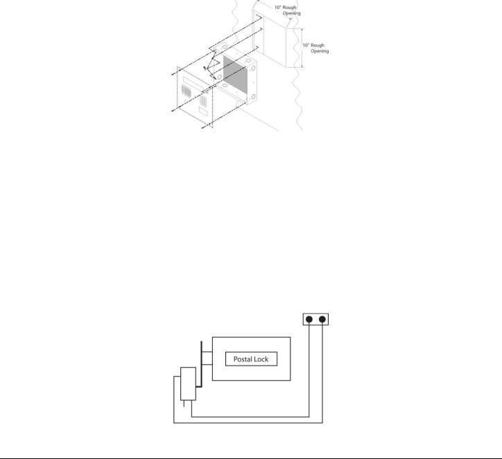
1.Cut a 10” x 10” square hole in the wall adjacent to wall stud.
2.Install back box using 3 - #10 screws. Wood screws for wood studs and metal screws for metal studs.
3.Punch through knockouts and run cables as required.
4.After all electrical connections are made, place front panel against back box and fasten with supplied security screws.
Figure 2 - Chassis Installation
Connecting the Postal Lock Switch
The common connection (black wire) is connected to one terminal of the postal lock terminal connector.
For a standard postal lock the NC connection (white wire) is connected to the other terminal of the postal lock terminal connector.
The standard postal lock is configured so that the bolt is retracted when the lock is engaged. (Key turned in lock). Ensure the postal lock is mounted so that the switch lever moves when the postal lock is engaged. Do not connect the postal lock switch until the postal lock is installed.
Postal Lock Switch
File:CV-TAC400_IN_MAN_NF_REV6.doc
Revised: September 2, 2014
Part No: 40-82B113
CV-TAC400 Installation Guide | 9
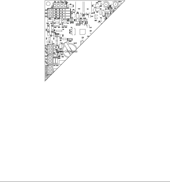
Adjusting the Speaker and Microphone Volume
The volume controls for the speaker and the microphone are found on the rear of the front panel. There are 2 volume control potentiometers located at the top center of the main PCB as shown below marked SPKv and MICv.. Adjust the controls clockwise to increase the volume/microphone levels and counter clockwise to decrease the levels.
Speaker and Microphone Volume Controls
File: CV-TAC400_IN_MAN__NF_REV6.doc
Revised: September 2, 2014
Part No: 40-82B113
CV-TAC400 Installation Guide | 10
Software
Installing the SFT5202 Software
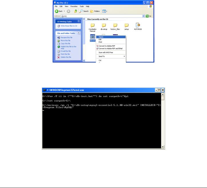
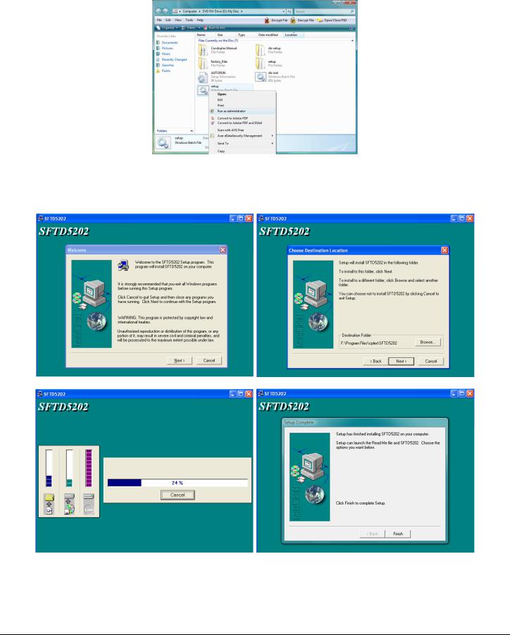
1.On a Windows XP system, follow the steps below:
a.Insert the CD into the computer.
The system will open a dialog box allowing you to choose what to do with the CD. Choose the
“Open Folder to View Files…” option. (if a window doesn’t automatically open use the Windows
Explorer to view the files on the CD).
b.Select the “db-inst.bat” file with the right mouse button. A menu will open up next to the file.
In that menu select the “Open” option. A command window will open, processes will run automatically and the command window will close. If a security screen appears allow the installation to proceed.
c. Select the “setup.bat” file with the right mouse button. A menu will open up next to the file.
File: CV-TAC400_IN_MAN__NF_REV6.doc
Revised: September 2, 2014
Part No: 40-82B113

CV-TAC400 Installation Guide | 11
In that menu select the “Open” option. A command window will open and an installation screen will appear. Follow the directions on the screen. If a security screen appears allow the installation to proceed.
d.When the installation is complete restart the system.
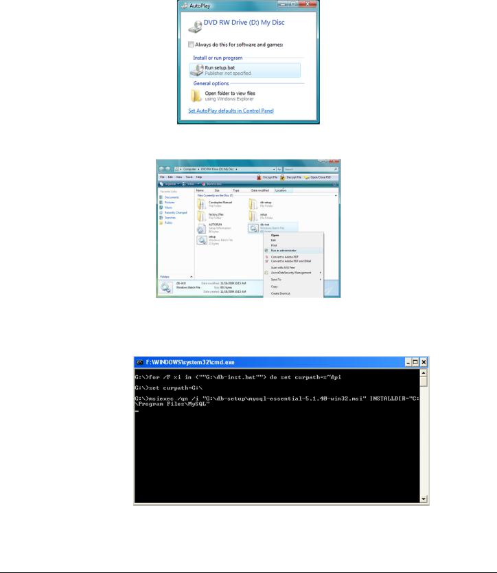
2.On a Windows Vista system, follow the steps below:
a.Insert the CD into the computer.
File: CV-TAC400_IN_MAN__NF_REV6.doc
Revised: September 2, 2014
Part No: 40-82B113
CV-TAC400 Installation Guide | 12
The system will open a dialog box allowing you to choose what to do with the CD. Choose the
“Open Folder to View Files…” option. (if a window doesn’t automatically open use the Windows
Explorer to view the files on the CD)
b. Select the “db-inst.bat” file with the right mouse button. A menu will open up next to the file.
In that menu select the “Run as administrator” option. A command window will open, processes will run automatically and the command window will close. If a security screen appears allow the installation to proceed.
c. Select the “setup.bat” file with the right mouse button. A menu will open up next to the file.
File: CV-TAC400_IN_MAN__NF_REV6.doc
Revised: September 2, 2014
Part No: 40-82B113
CV-TAC400 Installation Guide | 13
In that menu select the “Open” option. A command window will open and an installation screen will appear. Follow the directions on the screen. If a security screen appears allow the installation to proceed.
d. When the installation is complete restart the system.
File: CV-TAC400_IN_MAN__NF_REV6.doc
Revised: September 2, 2014
Part No: 40-82B113

14 |
3  Configurations
CV-TAC400 integrated telephone entry and access control system is ideal for multi-unit residential and commercial buildings, with up to 500 suites/names. As a stand-alone telephone entry system, CV-TAC400 provides maximum performance, durability and economy. In a multi-panel (up to 3 slave panels), integrated configuration (telephone entry and card access) or with multiple locations, CV-TAC400 provides unprecedented performance and value.
This application guide will cover the minimum steps required for you to install and program the CV-TAC400 in some of the most common configurations.
1.Basic Master Configuration
2.Master with Internal Access Control Reader
3.Basic Master with Slave
4.Basic Master with Slave Unit and Access Control
Each section contains complete and comprehensive instructions on the physical connections and the software programming required to get your CV-TAC400 system operational as efficiently as possible.
File:CV-TAC400_IN_MAN_NF_REV6.doc
Revised: September 2, 2014
Part No: 40-82B113
15 |
3.1 Configurations
Basic Master Configuration
These instructions are for a CV-TAC400 configured as a master device to call suites over the telephone and allow entry through a single door when the correct telephone key is pressed.
Hardware Connections
All hardware connections are to be made before applying power to the unit.
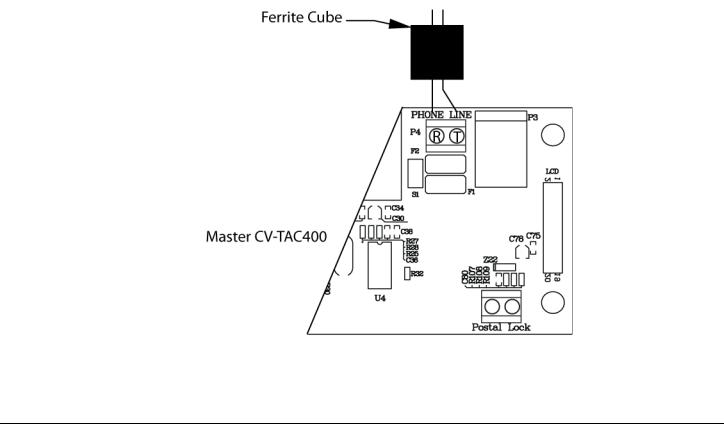
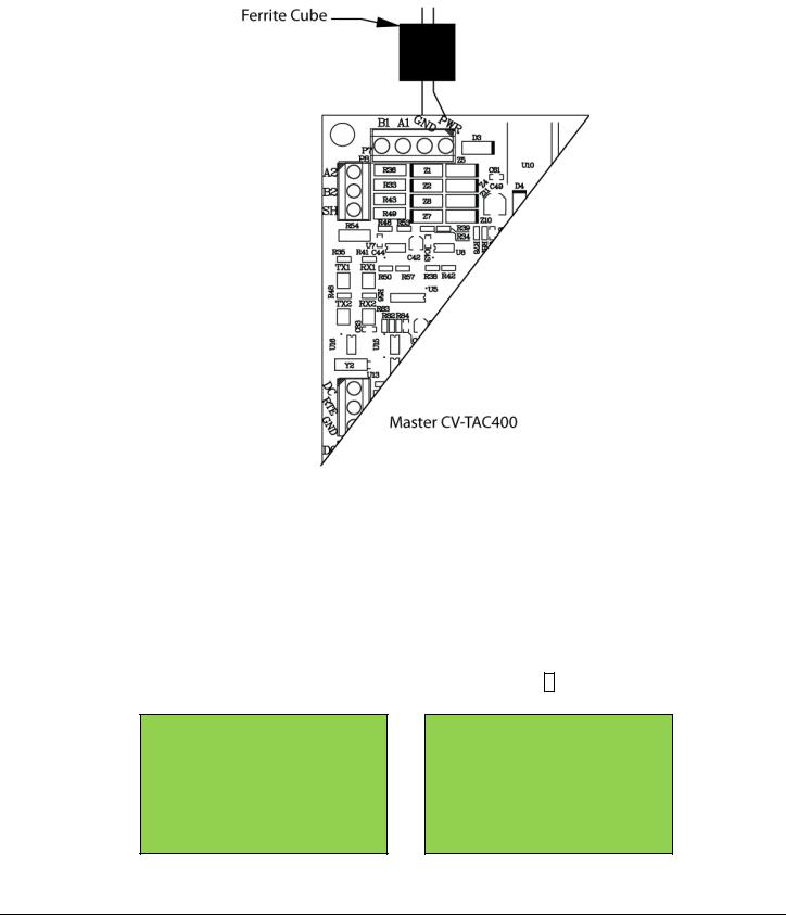
Using the Ferrite Cubes
To maintain compliance with emission standards the installer must install the supplied Ferrite Cubes on the Power and Telephone line connections. Each connection is passed through its own cube.
The power connections (GND, PWR) must be passed through the hole in the supplied ferrite cube
The telephone line must be passed through the hole in the other supplied ferrite cube.
1.Connect the Telephone Line
A dedicated telephone line is required. TIP and RING connections are provided to allow connection to a telephone line. Typically, TIP is green and RING is red.
Figure 3 - Master CV-TAC400 Tip and Ring Connections
File:CV-TAC400_IN_MAN_NF_REV6.doc
Revised: September 2, 2014
Part No: 40-82B113
CV-TAC400 Installation Guide | 16
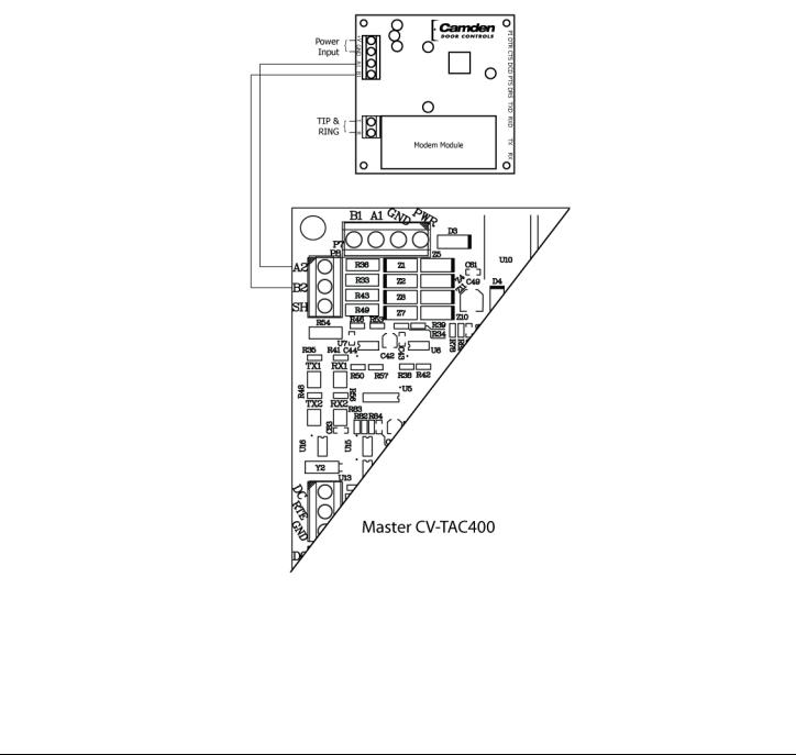
2.Connect the Modem Module (Optional)
An optional CV-TAC4M modem module is used to connect to a remote computer for programming the CV-TAC400. The remote computer must have a modem connection and calls the CV-TAC400. Details of programming the CV-TAC400 are contained in the section “Remote Connection Using a Modem”
When a modem connection is used the CV-TAC400 must be configured to use a shared phone line.
The telephone line connected to the modem module may be the same telephone line used by the CVTAC400 to call the suites.
Figure 4 - Optional Modem Module Connection
File: CV-TAC400_IN_MAN__NF_REV6.doc
Revised: September 2, 2014
Part No: 40-82B113
CV-TAC400 Installation Guide | 17
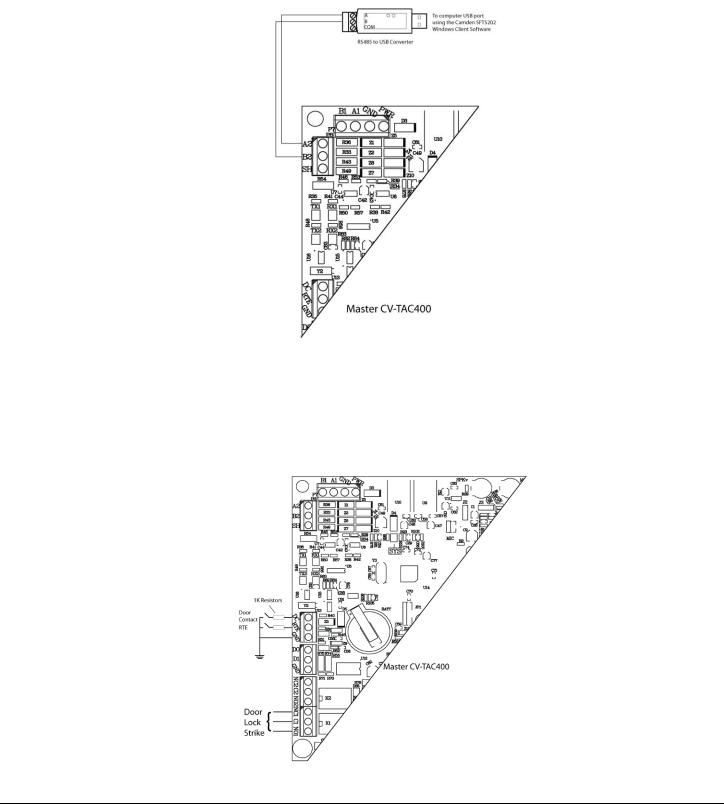
3.Connect the Computer
If you are not using the modem module above, a direct connection to a computer is required for programming the CV-TAC400. An RS485 to USB converter is used. Connect the RS485 Converter as shown in Figure 5.
Figure 5 - RS-485 Connection to Computer
4.Connect the Door Lock
Connect the door lock to the door relay and door lock power. The exact nature of the connection depends on the specific lock used. (Figure6)
Figure 6 - Door Strike Connections
File: CV-TAC400_IN_MAN__NF_REV6.doc
Revised: September 2, 2014
Part No: 40-82B113
CV-TAC400 Installation Guide | 18
5.Connect the Power
Connect power (12 VDC) to the CV-TAC400 power connections on Port 1. (Figure 7)
Figure 7 - Door and Power Connections
6.Set the Time and Date
Setting the time and date requires you to login to the CV-TAC400 locally via the front panel.
A. Logging In
To access the service mode the user must login with a password. To do this, follow the steps below:
Press and hold the 1, 4 and 7 buttons until the display shows “Enter password [_ ]”. Enter the CV-TAC400’s password. The default Password is “1234#”.
The Main Menu will be displayed.
Main Menu
 1. Event Log
2.Data Display
3.Service Menu
4.Date and Time
5.Exit
Note: To access additional menu items press # to move down and * to move up the menu.
File: CV-TAC400_IN_MAN__NF_REV6.doc
Revised: September 2, 2014
Part No: 40-82B113

CV-TAC400 Installation Guide | 19
 If you enter the wrong password five times in a row, you will be locked out of the unit for 2Hrs. Even the help code will not be available.
If the wrong password is entered the display will show: “Password Incorrect”. You may then repeat the process.
From the main menu select 4. Date & Time
The Date and Time menu allows changing the CV-TAC400’s date and time. When the Date and Time menu is selected a display similar to the example figure below will be displayed.
ELP Time and Date: 2009–Oct-19 Monday 16:14:16
To change the date or time you position the cursor under the item you want to change and then use the 1 and 3 keys to increment or decrement that item. The # key moves the cursor right and at the end of the line moves down to the next line. The * key moves the cursor left and at the left end of the line the cursor moves up to the next line.
When you have finished changing the date and time the 0 key exits to the main menu.
The following table summarizes how the keys affect the display:
Key |
Action |
# |
Moves cursor right and down |
* |
Moves cursor left and up |
1 |
Increments the value above the cursor |
3 |
Decrements the value above the cursor |
0 |
Exits the date and time menu |
7.Set the DIP Address of the CV-TAC400 to 1
From the front panel of the Master CV-TAC400, select 3 Service Menu from the Main Menu. Select ‘2’, Change ELP Address.
Service Menu
 1. Change password
2.Change ELP Address
3.ELP Setup Menu
4.ELP Status Menu
5.Dispatch / Request Data
6.Restore ELP Default
7.Exit
To change the CV-TAC400 DIP Address, enter the new address using the number keys. Select an
File: CV-TAC400_IN_MAN__NF_REV6.doc
Revised: September 2, 2014
Part No: 40-82B113

CV-TAC400 Installation Guide | 20
address from the table below. To save the address you have just entered, press the # key. To exit without changing the password enter the * key.
There must be one and only one Master CV-TAC400. Each system may have up to 3 slave CV-
TAC400’s. The addresses must be unique within each system.
Address |
CV-TAC400 Operation |
1 |
CV-TAC400 Master |
14 |
CV-TAC400 Slave 1 |
15 |
CV-TAC400 Slave 2 |
16 |
CV-TAC400 Slave 3 |
8.Starting the SFT5202 Windows Client Software
The following instructions apply only if the default file locations were used in the software installation. If any changes were made that location should be used.
To start the SFT5202 Windows Client Software open (double click) the SFT5202 icon on the desktop If there is no SFT5202 icon on the desktop the following steps may be performed:
a.select the Start Menu from the windows desktop
b.select Programs from the start menu
c.select the “remoteAdmin” folder
d.select SFTD5202D from the list. The main SFT5202 Windows Client Software window will be displayed
9.Establishing a Connection with the CV-TAC400
The CV-TAC400 is programmed via a Windows PC, using an USB to RS485 converter for local access or an optional CV-TAC4M Modem Module for a remote dialup connection.
Remote Connection Using a Modem
Overview
The CV-TAC400 may be connected to a computer system over a telephone line. To do this the CVTAC400 requires the modem module. The computer requires a modem connected to it and the SFTD5202 software.
Using the modem is identical to the RS485 connection after the connection has been made. Because a computer with a modem may be used to manage multiple CV-TAC400’s, the “Open Session” initialization is not used. Downloading and uploading data using the modem is described below in sub-section 11 - ‘Open a Session with the CV-TAC400 (Working Online with a Modem Connection) and sub-section 16, Part B –
‘Uploading Saved Information into the CV-TAC400 – Working Online Using the Modem Module’.
The telephone number and password for each building must be entered into the system. When you wish to update that particular building the dialing information can be selected from that list.
File: CV-TAC400_IN_MAN__NF_REV6.doc
Revised: September 2, 2014
Part No: 40-82B113
CV-TAC400 Installation Guide | 21
Configuring the SFTD5202 Software for the Modem
Overview
Each time the modem is used the modem must be initialized. Once the modem is initialized it may be used until the SFTD 5202 software is closed.
Finding the COM Port
To identify the modem to the SFTD5202 software the computer system gives it a name, such as COM3. To use the modem you must know its COM port number. Determining the COM port varies depending on the computer’s operating system.
Different versions of the operating system will have different methods for determining the COM port. The following discussion may not exactly match your particular system. In general, for Windows Operating systems the “Control Panel” will have an icon for modem options. It may be under the “Hardware and Sound” Icon or directly visible. Selecting it will show which COM port the modem is connected to.
Changing the Settings
a.To change the communications settings follow the steps below:
b.Start the SFT5202 Windows Client Software
c.Select the “Setup” menu. A list of submenus will be displayed
d.Select the “Communications” submenu. The “Communication Setting” form will be displayed
e. In “Connection” box select Modem.
File: CV-TAC400_IN_MAN__NF_REV6.doc
Revised: September 2, 2014
Part No: 40-82B113

CV-TAC400 Installation Guide | 22
f.In the “Com Port” drop down box, select the COM Port the Modem is connected to.
g.In the “Data Bits” box select 8.
h.In the “Flow Control” box select “none”.
i.In the “Parity” box select “None”.
j.In the “Stop Bits” box select “1”.
k.In the “Echo” box select “”Off”.
l.When you are done Save the settings by selecting the “Save Settings” button
Initializing the Modem
NOTE: The modem will remain initialized until the SFTD5202 software is shutdown. This initialization procedure must be performed each time the SFTD5202 software is restarted.
To initialize the modem follow the steps below:
a. Ensure the “Communication Setting” form is displayed.
b. Select the “Save” button.
File: CV-TAC400_IN_MAN__NF_REV6.doc
Revised: September 2, 2014
Part No: 40-82B113

CV-TAC400 Installation Guide | 23
c. The modem is initialized.
Setting the Remote Modem
Overview
Each remote site that this system connects to will have an associated password and phone number. These may be stored in a list so that they may be easily accessed.
Setting up a Remote Modem
To add a remote site and its phone number and password to the list of sites follow the steps below:
a.Start the SFT5202 Windows Client Software.
b.Select the “Setup” menu. A list of submenus will be displayed
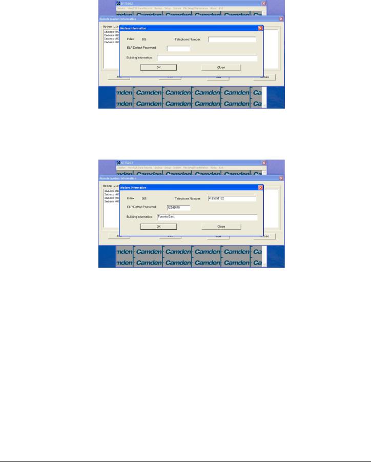
c.Select the “List Remote Modem(s) Setting” submenu. The “Remote Modem Information” form will be displayed.
d. Select the “Add” button. The “Modem Information” form will be displayed
File: CV-TAC400_IN_MAN__NF_REV6.doc
Revised: September 2, 2014
Part No: 40-82B113
CV-TAC400 Installation Guide | 24
e.Enter the Remote telephone number in the “Telephone Number” box.
f.Enter the Remote modem Password in the “ELP Default Password” box.
g.Enter the Building Identification in the “Building Information” box.
h. Select “OK” to save the information or “Close” to exit without saving
Starting a Connection
Overview
To communicate with a remote system via modem you must first start the connection. As the system does not know which system will be connected you do not use start session.
Starting the Connection
a.To start a connection to a remote system follow the steps below:
b.Start the SFT5202 Windows Client Software.
c.Select the “Setup” menu. A list of submenus will be displayed
File: CV-TAC400_IN_MAN__NF_REV6.doc
Revised: September 2, 2014
Part No: 40-82B113
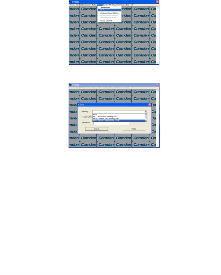
CV-TAC400 Installation Guide | 25
d. Select the “Dial Up” submenu. The “Dial Up” form will be displayed.
e.Select the remote site from the list of remote sites in the “Building” drop down list. If the building is not in the list you may enter the information in the form.
f.Select the “Dial up” button to start the connection or Close to exit with starting the connection.
File: CV-TAC400_IN_MAN__NF_REV6.doc
Revised: September 2, 2014
Part No: 40-82B113
CV-TAC400 Installation Guide | 26
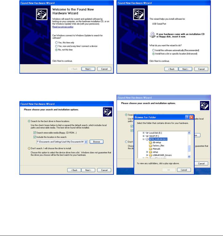
RS485 to USB Converter
Plug the USB to RS485 converter into an empty USB port on your computer. A prompt to search the internet for a driver will pop up. Select ‘No, not this time’ Press Next. In the next window, select ‘Install from a list or specific location [Advanced]’
Select ‘Include this location in the search’ and press Browse. In the Browse For Folder window, select the software CD supplied with your system.
File: CV-TAC400_IN_MAN__NF_REV6.doc
Revised: September 2, 2014
Part No: 40-82B113

CV-TAC400 Installation Guide | 27
Open the USBtoRS485_Drivers folder and select the CM20602 folder. Press OK. Select Next to start installing the driver.
The driver will be installed. Select Finish when done.
File: CV-TAC400_IN_MAN__NF_REV6.doc
Revised: September 2, 2014
Part No: 40-82B113
CV-TAC400 Installation Guide | 28
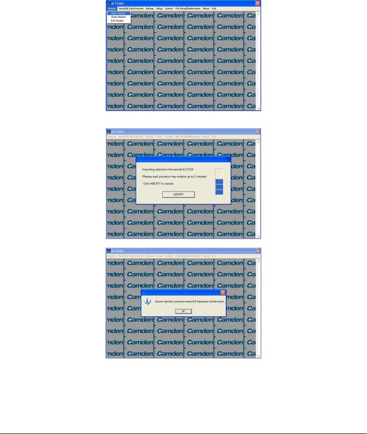
10.Open a Session with the CV-TAC400 (Working Online with an RS485 Converter)) a. Select the Session Menu.
b. Select Open Session.
c. Select OK when the session has finished loading.
11.Open a Session with the CV-TAC400 (Working Online with a Modem Connection) a. Select the “File Setup/Maintenance” menu and select “Import Data from an CV-TAC400(s).
File: CV-TAC400_IN_MAN__NF_REV6.doc
Revised: September 2, 2014
Part No: 40-82B113
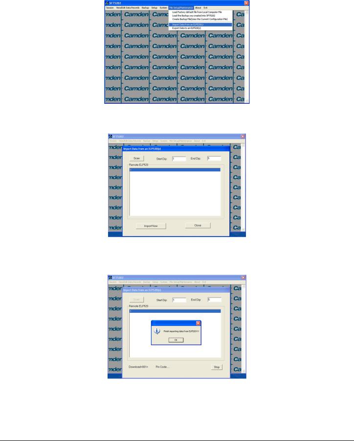
CV-TAC400 Installation Guide | 29
b.Scan for Remote CV-TAC400s. Select the remote CV-TAC400 from the list you wish to communicate with.
c.The CV-TAC400’s data will be imported. The download from the remote CV-TAC400 can take up to 5 minutes.
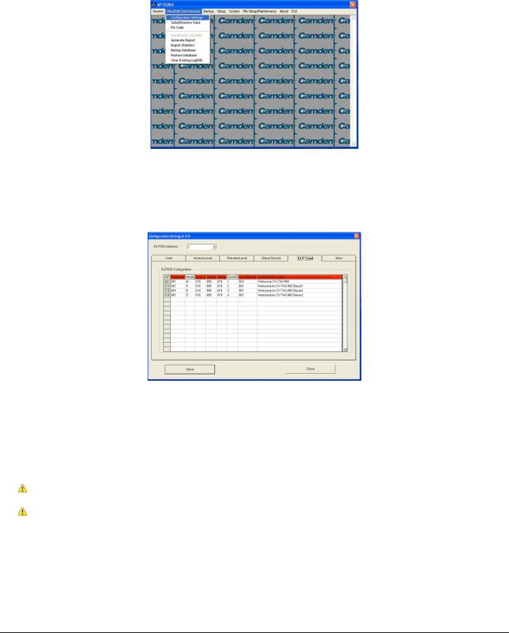
12.Changing the Greeting Message
To change the Greeting Message, perform the following steps:
a) Select the “View/Edit Data Records” Menu. A list of submenus will be displayed.
File: CV-TAC400_IN_MAN__NF_REV6.doc
Revised: September 2, 2014
Part No: 40-82B113
CV-TAC400 Installation Guide | 30
b)Select the “Configuration Settings” submenu. The Configuration setting window will be displayed. Do not change the CV-TAC400 Address field at the top of the window.
c)Select the “ELP Conf” tab. The ELP Configuration table will be displayed
d)Open (Double click on) the “Greeting Message” field of the CV-TAC400 you wish to change. The field will open for editing. You may change the text as required.
e)When the editing is complete press the “enter” key or select anywhere else in the “ELP Conf” table.
f)Save and Upload the changed information.
13.Load the Factory Default
Using this file will erase all previously saved data.
The default factory file is located on the installation CD.
Start by selecting a file of current information. To do this, follow the steps below
a. Select the “File Setup/Maintenance” menu. A list of submenus will appear below.
File: CV-TAC400_IN_MAN__NF_REV6.doc
Revised: September 2, 2014
Part No: 40-82B113
 Loading...