


CM-RX-90v2
Page 1 of 7
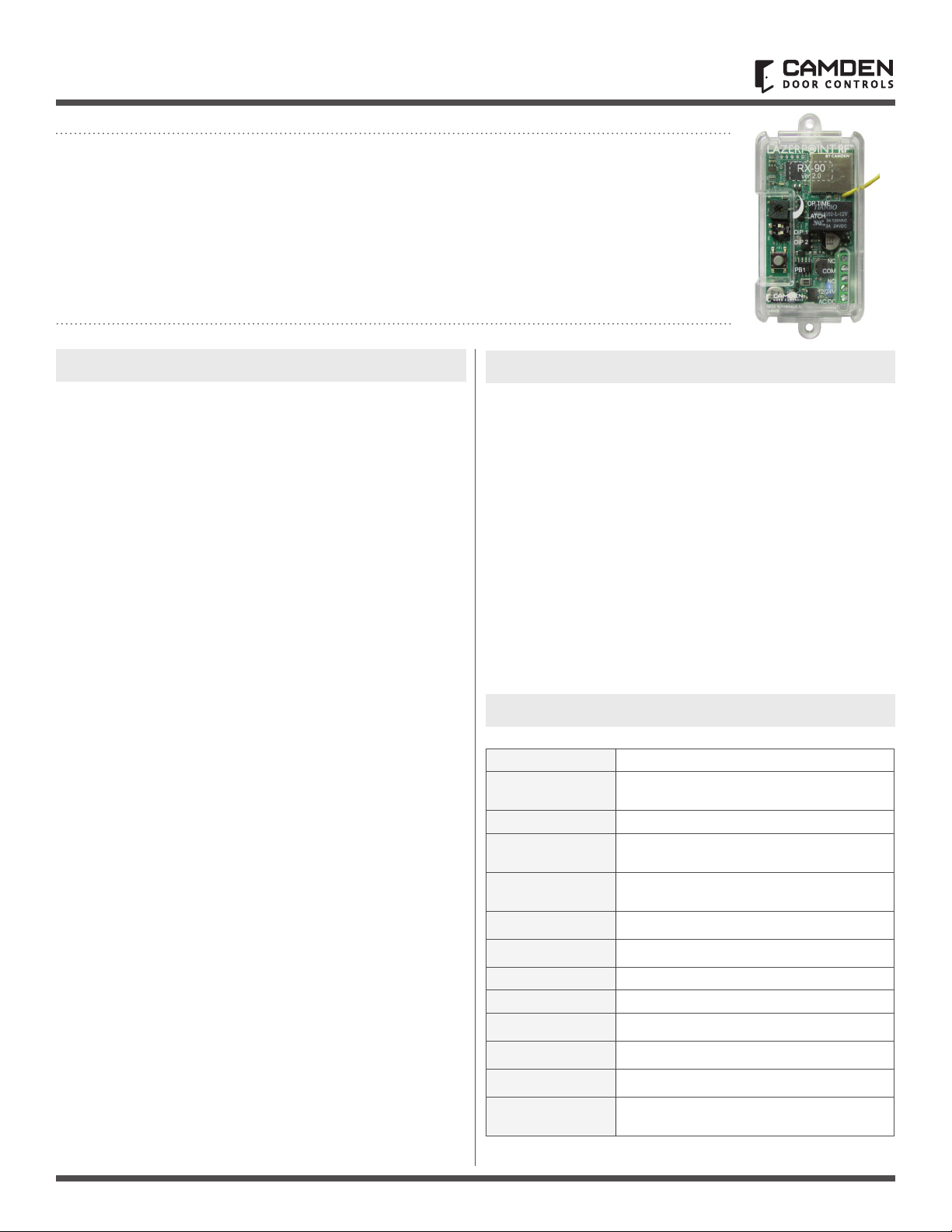
Lazerpoint™ RF RX-90v2
Advanced Single Relay Receiver
INSTALLATION INSTRUCTIONS
Door Activation Devices
1. DESCRIPTION
CM-RX-90v2 receivers can be paired with Lazerpoint™ or
Kinetic™ transmitters, switch selectable.
Kinetic™ by Camden is an advanced 900 MHz 'power harvesting'
wireless system that uses the energy created by the operation
of the switch to power the wireless transmitter.
This Kinetic™ transmitter is available with the following push
plate switches: CM-45K, CM-46K, CM-7536K and CM-7509K.
Lazerpoint™ Radio Controls comprise the following models:
• CM-TX-9 Wall switch ready transmitter
• CM-TX-99 Plug-in transmitter
• CM-TXLF 1, 2 & 4 button fob transmitters
• CM-RX-90v2 Advanced single relay receiver
• CM-RX-91 Basic single relay receiver
• CM-RX-92 Full function (dual relay) receiver
Lazerpoint™ RF is the rst system designed to address the
specic needs of the Automatic Door industry. Unlike typical
“garage door” RF, Camden’s Lazerpoint™ operates at 915 MHz
frequency to “cut through” noise and clutter, penetrating typical
building materials to ensure a reliable installation.
Three receiver models are offered – the basic single relay RX-91,
the full function RX-92 and the advanced single relay RX-90v2.
The RX-90v2 offers 3 operating modes including delayed, no
delay and latched.
The CM-RX-90v2 supports both Lazerpoint™ RF and
Kinetic™ by Camden transmitters.
CM-RX-90v2 features a convenient terminal block, visual relay
status, and 40 code memory with push and learn technology.
2. FEATURES
• 3 Modes of Operation:
- Delayed (1 - 15 Seconds)
- No Delay (1 – 30 Seconds)
- Latching
• Adjustable Range: 3' - 300'
• 40 Transmitter capacity, either Lazerpoint™ or Kinetic™
either delayed, non-delayed or both
• Form ‘C’ Relay Output
• 12/24V AC/DC operation
• 915 MHz Lazerpoint™ or Kinetic™ Technology
• Small Size: 2-5/8”H x 1-1/2”W x 13/16”D (67mm x 38mm x 21mm)
3. SPECIFICATIONS
Operating Voltage 12/24V AC/DC
Current Draw
23 mA nominal @ 24 VAC
43 mA maximum @ 24 VAC
Response Time 30 – 200 ms
Memory Delay
& No Delay
40 transmitters total
LED’s
Indicate: relay status; learn mode;
erase mode & potentiometer position
Output 1 x SPDT Relay contact
Rating 3 amps @ 30 VDC
Operating Time 1 – 30 seconds
Delay Time 1 – 15 seconds
Frequency 915 Mhz.
Mounting 2-#4 screws at 3” centers or Velcro (supplied)
Enclosure Clear plastic case
Dimension 2-5/8”H x 1-1/2”W x 13/16”D
(67mm x 38mm x 21mm)
LAZERPOINT™ RF RX-90v2 ADVANCED SINGLE RELAY RECEIVER
INSTALLATION INSTRUCTIONS
Page 2 of 7
4. INSTALLATION
MOUNTING
The RX-90v2 receiver is designed to mount inside the automatic
door header. Screw holes are located at each end of the receiver
case, or the included velcro may also be used to hold it securely.
For dimensional information refer to RX-90v2 electrical and
mechanical Drawing on Page 4.
WIRING
Note: Do not use the Kinetic/Lazerpoint RF system as a safety
device! If safety devices are used, always wire directly to the
operator control box.
Refer to the RX-90v2 Wiring Diagram on Page 5, and wire the
receiver as follows:
Wire the device (electric lock / operator) to the Relay output -
terminal 3 is N.O. 4 is Common and 5 is N.C.
Connect 12 or 24V AC/DC
to terminals 1 & 2 on the
receiver. (Terminals are
not polarity sensitive)
5. SET-UP INSTRUCTIONS
Note: Some switches that have more than one transmitter
(CM-7536(K)) will have to have both individually learned into the
CM-RX90v2. This will affect how many devices can be learned in
since the total number of transmitters per CM-RX90v2 is 40 and
not 40 devices.
STEP 1
Learning the Transmitter(s) to the Receiver
A receiver can have up to 40 transmitters paired with it. The
transmitter can be paired as Kinetic™/ Lazerpoint™ delayed,
non-delayed or a combination of both, making RX-90v2 ideal
for bi-directional door sequencing.
Set the RF Transmitter Type
Set DIP2 to ON Kinetic™, DIP2 to OFF Lazerpoint™
Learning the Transmitter in Delayed Mode
Set DIP1 to ON.
Press PB1 using a small blunt object such as a small blade
screwdriver or similar. Within 10 seconds, press the switch
connected to a TX-9 transmitter or a button on a Lazerpoint™
FOB or Kinetic™ switch. The Green LED Array ashes to conrm
enrollment. Repeat with any additional transmitters. Pressing
the learned transmitter again will signal the receiver that you are
nished programming and the LED will ash rapidly.
Pressing the transmitter a third time activates the relay, LED, and
the device connected to the relay contacts after the delay time
set by POT1. If you wait longer than the 10 second period, the
receiver times out of Learn Mode and reverts back to standby.
Learning the Transmitter in No-Delay Mode
Set DIP1 to OFF
Press PB1 using a small blunt object such as a small blade
screwdriver or similar. Within 10 seconds, press the switch
connected to a TX-9 transmitter or a button on a Lazerpoint™
FOB or Kinetic™ switch. The Green LED Array ashes to conrm
enrollment. Repeat with any additional transmitters. Pressing the
learned transmitter again signals the receiver that you are nished
programming and the LED will ash rapidly.
Pressing the transmitter a third time will activate the relay, LED, and
the device connected to the relay contacts. If you wait longer than
the 10 second period, the receiver times out of Learn Mode and
reverts back to standby.
STEP 2
Adjustments
The delay before operate and relay On-Time are controlled by POT1.
Delayed Mode
The RX-90v2 has a delay before operate timer.
Set DIP1 to ON.
Adjust POT1 clockwise to increase the delay timer from 0 to 15
seconds. The LED lights and become brighter as the delay time
is increased and becomes dim as the delay time is decreased.
The LED starts to ash once the maximum delay time has been
reached. Back off the delay time until the LED is solid again for
maximum delay time.
No-Delay Mode
The RX-90v2 can be adjusted to activate the output relay without
a delay. The relay On-Time is adjustable from 1 to 30 seconds.
Set DIP1 to OFF.
Adjust POT1 Clockwise/counterclockwise to adjust the relay
On-Time (1 to 30 Seconds). To increase the time, turn the pot
clockwise, or for minimum time, turn the pot counterclockwise.
The LED lights and becomes brighter as the Relay On-Time is
increased. The LED starts to ash once the maximum On-Time
has been reached. Back off the POT until the LED is solid again for
maximum On-Time.
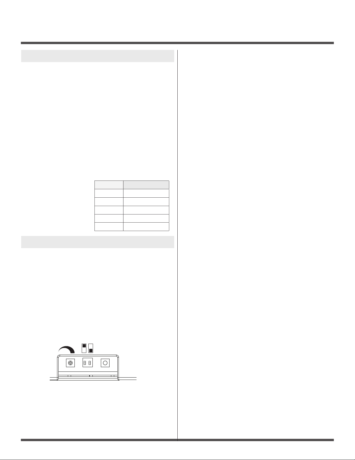
2
ON
1
POT1 PB1
DIP 1
DIP 2
Terminal Description
1
Power in
2
Power in
3
Normally Open
4
Common
5
Normally Closed

LAZERPOINT™ RF RX-90v2 ADVANCED SINGLE RELAY RECEIVER
INSTALLATION INSTRUCTIONS
Page 3 of 7
Latching Mode
The RX-90v2 has a latching mode. Activating the transmitter will
latch the output relay ON. Activating the transmitter a second
time will latch the Relay OFF.
DIP1 can be set to either ON/OFF.
Adjust POT1 clockwise until the LED starts to ash. RX-90v2 is in
latching mode at this point. To remove latching mode, turn POT1
counter clockwise until the LED is solid again.
Note: Latching mode disables delayed mode. Transmitter
programmed as delayed mode will work as latching
mode transmitter.
Signal Strength Adjustment
For the most reliable, consistent operation, leave the signal
strength at full power. RX-90v2 receiver has an adjustment RF
range from a few feet to full range (300 ft. LOS).
To adjust the RF range:
1. Press PB1 to enter pairing mode.
2. Press PB1 again until the LED ickers 3 times. This places
the receiver in RF range adjust mode.
3. Adjust POT1 to adust the RF range. CW to increase the range,
CCW to decrease the range.
4. Press a paired transmitter to test range as it is being adjusted.
5. Once the desired range is set, Press and hold PB1 until LED
ickers 3 times. The transmitter is now back in pairing mode.
Either wait for the receiver to time out or press a paired
transmitter to exit pairing mode. After adjusting the range you
MUST adjust POT 1 for relay timing at this point based on the
mode (delay or no-delay).
STEP 3
DELETING TRANSMITTERS
Delay Mode Transmitters
Set DIP1 to ON.
Pressing and holding PB1 for 8 seconds deletes all transmitters
delay mode. LED ashes rapidly for 4 seconds, indicating erasure
of the codes.
No Delay Mode Transmitters
Set DIP1 to OFF.
Pressing and holding PB1 for 8 seconds deletes all transmitters
no delay mode. The LED ashes rapidly for 4 seconds, indicating
erasure of the codes.
Note that individual removal of specic codes is not possible.
6. WARRANTY
Camden Door Controls guarantees the Lazerpoint™ RF to be free
from manufacturing defects for 3 years from date of sale.
If during the rst 3 years a Lazerpoint™ RF component fails to
perform correctly, it may be returned to our factory where it will be
repaired or replaced (at our discretion) without charge.
Except as stated herein, Camden extends no warranties expressed
or implied regarding function, performance or service.
NOTE: Batteries are exempt from this warranty!
 Loading...