


Camden Door Controls CM-331-40, CM-331-41, CM-331-42, CM-331-43, CM-331-44 User Manual
...CM-331 & CM-332 Series
Active Infrared “Hands-Free” Switches
Installation Instructions
Section 1: General Description
Sure-Wave™ hands-free switches are active infrared devices designed for use with an automatic door operator or other access control products.
Applications include low-energy doors, drive-up windows, health-care facilities, manufacturing… etc.
These units will fit in a variety of locations from 1 ¾” door frames to single and double gang electrical boxes. Various sized surface mount boxes are available from Camden.
There are 2 Line Powered models available:
CM-331 – Single relay output CM-332 – Dual relay output
Three standard faceplates widths are available:
Jamb Mount /N: 1 ¾” x 4 ½” polycarbonate or stainless steel, fits 1 ¾” door frames or our CM-23D jamb box.
Single Gang: 2 ¾” x 4 ½” polycarbonate or stainless steel, fits on single gang electrical boxes
Double Gang /W: 4 ½” x 4 ½” polycarbonate or stainless steel, fits on double gang or 4 x 4 electrical boxes.
All faceplates are available with a variety of graphics/text: /40 Waving Hand symbol
/41 Waving Hand Icon and Wave to open text
/42 Waving Hand Icon, Wave to Open text and Wheelchair symbol
Light Ring – SGLR Option
Camden CM-331 and CM-332 Sure-Wave are available with a light ring option. This provides an illuminated ring for visual confirmation of the switch activation. The light ring can be set to various combinations of colors, Blue, BlueRed, or Green-Red.
BY CAMDEN
CM-TX-99 RF Module
Camden CM-331 and CM-332 Sure-Wave can be fitted with an optional Lazerpoint CM-TX-99 RF Module. The CM-TX-99 RF Module enables the Sure-Wave to product an RF output when activated, that is compatible with our Lazerpoint Series receivers.
Section 2: Installation
Mounting
Sure-Wave may be mounted in door jambs, single or double gang electrical boxes, and 4 x 4 boxes.
NOTE:
The sealing gasket (included) is recommended for outdoor or wet locations. If using with Automatic doors install in accordance with ANSI A156.10 / A156.19. Select from one of the following three mounting subsections:
Single Gang Electrical Box: CM-331 & CM-332
1a – If using an in-wall box ensure the box is plumb and square, and flush with the wall surface. (See Diagram 1)
1b – If using a surface box, ensure it is secure & plumb.
2 – Bring your 4-conductor wire through the back or side of the enclosure and leave approximately 6” tail for wiring connection.
3 – Make the electrical connections to the device according to the wiring section (following).
4 – Using the dip switch located on the end of the unit, set the operating mode. (See Section 4)
5 – Attach the unit to the enclosure using the two #6-32 screws provided.
6 – Apply power and adjust range and time delay via the potentiometers on the front of the unit. (See Section 4 for adjustments)
7 – Attach the faceplate to the unit using the two black #6-32 x 3/8 machine screws or tamperproof screws.
Do not overtighten!!
Page 1 of 8

CM-331 & CM-332 Active Infrared “Hands-Free” Switches Installation Instructions
Smooth
Wall Finish
Wall 


Flush |
|
Wall Box |
|
Rough Wall |
|
Finish |
|
Recessed |
Unaligned |
Box |
Box |
2-Gang (or 4x4) Electrical Box: CM-331W & CM-332W
Diagram 1 - Proper Box Installation
1a – If using an in-wall box ensure the box is plumb and square, and flush with the wall surface. (See Diagram 1)
1b – If using a surface box, ensure it is secure & plumb.
1c – If using a 4 x 4 box, ensure the box is plumb and square, and flush with the wall surface, then attach the metal adaptor plate (included in the CM-331W & CM-332W packages) to the box using appropriate fasteners.
2 – Bring your 4-conductor wire through the back or side of the enclosure and leave approximately 6” tail for wiring connection.
3 – Make the electrical connections to the device according to the wiring section (following).
4 – Using the dip switch located on the end of the unit, set the operating mode. (See Section 4)
5 – Attach the unit to the enclosure using the two #6-32 screws provided.
6 – Apply power and adjust range and time delay via the potentiometers on the front of the unit. (See Section
4for adjustments)
7 – Attach the faceplate to the unit using the two black #6-32 x 3/8 machine screws or tamperproof screws.
Do not overtighten!!
Door Frame: CM-331W & CM-332W
1a – If mounting directly in a 1¾” wide aluminum jamb, make a cutout in the door frame at the intended location as per Diagram 2 on page 4.
Drill and tap two mounting holes as shown.
1b – If mounting the unit in our CM-23d deep jamb box, first mount the jamb box according to the instructions packaged with the enclosure. Using the CM-23D as a guide, drill a wire access hole through the jamb to fish the wiring through.
2 – Bring your 4-conductor wire through the back or side of the enclosure (or Jamb) and leave approximately 6” tail for wiring connection.
3 – Make the electrical connections to the device according to the wiring section (following).
4 – Using the dip switch located on the end of the unit, set the operating mode. (See Section 4)
5 – Attach the unit to the enclosure or jamb using the two #6-32 screws provided.
6 – Apply power, and adjust range and time delay via the potentiometers on the front of the unit. (See Section 4 for adjustments)
7 – Attach the faceplate to the unit using the two black #6-32 x 3/8 machine screws or tamperproof screws.
Do not overtighten!!
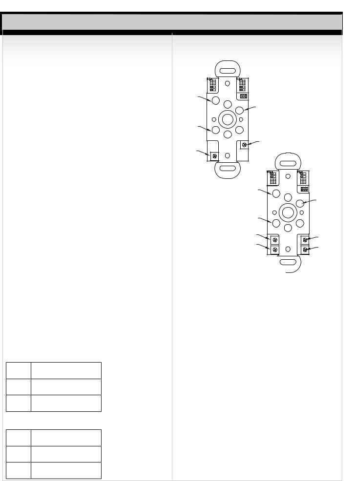
Wiring
|
N |
C |
N |
|
|
|
|
|
|
|
|
|
C |
O |
|
|
|
|
|
|
|
|
|
|
|
|
|
|
|
|
|
|
|
||
|
TB 3 |
|
|
|
|
|
|
|
|
||
|
Relay |
DIP 3 |
LED Control |
|
|
|
|
|
|||
|
|
1 |
|
4 |
|
|
|
|
|
||
Request To |
|
1 |
|
2 3 |
DIP Switch |
|
|
|
|
|
|
|
|
O N |
|
|
|
|
|
|
|
||
|
|
|
|
1 |
|
|
|
|
|
|
|
Exit Input |
|
2 |
|
TB 2 |
|
|
|
|
|
|
|
Door Contact |
|
3 |
|
|
|
Plugin for |
|
|
|
||
|
|
|
|
|
|
|
|
||||
Input |
|
4 |
|
|
|
|
|
|
|||
|
|
|
|
optional |
|
|
|
|
|||
External LED |
|
5 |
|
|
|
|
|
|
|
||
|
6 |
|
|
|
CM-TX-99 RF |
|
|
|
|||
Ring Control |
|
|
|
|
|
module |
|
|
|
|
|
|
TB 1 |
|
|
|
|
|
|
|
|||
|
|
|
|
|
|
|
|
|
|
||
CM-331 |
Power In Power In |
|
|
|
N C |
N |
|
N |
C |
N |
|
|
|
|
|
|
|
C |
O |
|
C |
|
O |
|
|
|
|
|
|
TB 3 |
|
TB 4 |
|||
|
|
|
|
|
|
Relay |
DIP 3 |
Relay |
|||
|
|
|
|
|
|
1 |
|
3 4 |
|
2 |
|
|
|
|
|
|
Request To |
|
|
1 2 |
|
|
LED Control |
|
|
|
|
|
1 |
|
O N |
|
|
DIP Switch |
|
|
|
|
|
|
Exit Input |
2 |
TB 2 |
|
|
||
|
|
|
|
|
|
|
|
||||
|
|
|
|
|
Door Contact |
3 |
|
|
|
|
Plugin for |
|
|
|
|
|
Input |
4 |
|
|
|
|
|
|
|
|
|
|
5 |
|
|
|
|
optional |
|
|
|
|
|
|
External LED |
|
|
|
|
||
|
|
|
|
|
Ring Control |
6 |
|
|
|
|
CM-TX-99 RF |
|
|
|
|
|
|
|
|
|
|
|
|
|
|
|
|
|
|
TB 1 |
|
|
|
|
module |
|
|
|
|
|
|
|
|
|
|
|
|
|
|
|
|
|
CM-332 |
Power In Power In |
|
|
|
|
|
Page 2 of 8
CM-331 & CM-332 Active Infrared “Hands-Free” Switches Installation Instructions
CAUTION:
Do not apply power to the unit until all secondary wiring is complete, and dip switches have been set.
Power – TB1
Camden CM-331/332 Sure-Wave switches can be powered from 12 or 24 Volts, AC or DC. Connect power to pins 1&2 on the TB1. This is a non-polarized connection.
Inputs
Camden Sure-Wave switches provide inputs for Door Contacts, Request to Exit and remote control of the LED
Light ring. These inputs are found on TB2. All inputs require a dry contact closure to operate.
TB2 Inputs
Pin |
Function |
Description |
Number |
||
|
|
|
1 |
Request to Exit |
A dry contact closure across these |
|
|
|
|
|
inputs will activate the relay(s) as per |
|
|
|
2 |
Request to Exit |
their settings. |
|
||
|
|
|
3 |
Door Contact |
Normally closed, Used for Security |
|
|
|
4 |
Door Contact |
Mode |
|
||
|
|
|
5 |
Remote LED |
External light ring control. A closed dry |
|
|
|
|
|
contact on this input will toggle the |
|
|
|
6 |
Remote LED |
light ring color. |
|
||
|
|
|
Outputs
The Sure-Wave switches provide Form ‘C’ relay outputs. The CM-331 has 1 Form ‘C’ output and the CM-332 has 2 Form ‘C’ outputs. Selecting the correct output is also dependant on the operating mode chosen. Most applications will utilize the N.O. and Common terminals.
Relay 1 Output (TB3)
1Normally Closed
2 Common
3Normally Open
Relay 2 Output (TB4), (CM-332)
1Normally Closed
2 Common
3Normally Open
Section 3: Applications & Set-up
Applications
DIP 1 |
DIP 2 |
|
|
||
LED Enable |
O N |
O N |
Motion Sensing |
|
|
2 1 |
2 1 |
|
|||
Audio Enable |
Modes |
|
|
||
Fail Safe |
4 3 |
4 3 |
Relay Operation |
||
EXT |
|
|
Modes |
|
|
Sounder |
|
|
J 1 |
|
|
|
|
|
Activate |
|
|
|
|
|
LED |
|
|
Error/Alarm |
|
|
|
|
|
LED |
|
|
|
|
|
|
|
|
POT 2 |
|
|
POT 1 |
|
|
Relay |
|
|
|
|
OP Time |
|
||
Range |
|
|
|
|
|
Adj. |
|
|
|
|
|
|
|
|
DIP 1 |
|
|
CM-331 |
|
LED Enable |
O N |
||
|
Audio Enable |
|
2 1 |
||
|
|
|
Fail Safe |
|
3 |
|
|
|
|
|
|
|
|
|
EXT |
|
4 |
|
|
|
|
|
|
|
|
Sounder |
|
|
|
|
|
Error/Alarm |
|
|
|
|
|
|
LED |
|
|
|
|
POT 3 |
|
|
|
|
|
Range Sequence |
|
|
|
|
|
Delay Adj. |
|
|
|
POT 1
Range Adj.
CM-332 
DIP 2
1 Motion Sensing |
|
O N |
Modes |
2 |
|
3 |
Relay Operation |
4 |
Modes |
|
J 1 |
|
Relay |
|
LED |
POT 2 |
Relay 1 |
OP Time |
POT 4 |
Relay 2 |
OP Time |
DIP 1 – Options Switch
SW1 – LED Enable
When SW1 is ON, the green LED will illuminate when the switch is activated. When SW 1 is OFF (default), the green LED will remain off.
SW2 – Audio Enable
When SW2 is ON, an audible beep is generated when the switch is activated. When SW2 is OFF (default), no audible beep is generated.
SW3 – Fail Safe/Fail Secure
This option changes the state of the relays on the Sure-Wave switches. When SW3 is ON, the relay outputs are switched. NO becomes NC and NC becomes NO. SW3 is OFF by default.
SW4 – External LED Control
The LED light ring can be controlled externally by providing a contact closure on the REM input (pins 5&6) on TB2. When SW4 is ON, a contact closure across the REM input will change the light ring color from its idle to active colors.
When SW4 is OFF, the light ring colors change with the state of the switch.
Page 3 of 8
 Loading...