


RMD 574BT Manual
INSTALLATION
Tools for Installation
Use the 2 removal wrenches of the old unit to take out the old unit and place with this brand new car radio. The following tools and supplies may also be needed for the installation:
Tools for Installation: Philips Screw-drivers /Machine Screws /Wire Stripper /Wire Cutter /Hammer /Pencil /Electrical Tape /Electric Drill Supplies for Installation: Machine Screws /Crimp Connectors /14 Gauge Wire for Power Connections /14-16 Gauge Speaker Wires
The above are not supplied.
Before you install
Automotive audio equipment installations can be challenging even to the most experienced of installation technicians. We strongly recommend that this unit should be professionally installed by a VAT registered installer (this is a requirement to validate the warranty). IMPORTANT: Remove the two transport screws from the top fo the unit before installing.
Remove the Old Unit from the Dashboard
1. Remove the outer t |
2. Insert the keys supplied with the |
|
old unit into both sides of the unit |
|
as shown in figure below until |
|
they click. Pull to remove the old |
|
unit from the dashboard. |
DIN Front Mount |
DO NOT DISCONNECT WIRES |
|
AT THIS TIME! |
Mark Polarity of the Speaker Wires
Marking the polarity of the speaker wirers will make it easier to connect the existing speakers to your car radio. Consult wiring diagram of existing head unit before disconnecting any wires. If you are not positive of the polarity of the existing wires from the speakers to the head unit, install new wires.
1.While the old unit is playing, disconnect the wires from one speaker.
2.Take a length of masking tape and fold it around the wire so it forms a flag.
3.On the masking tape mark the polarity of the speaker wires (+&-), as well as left or right, and front or rear.
4.Double check that you marked the first speaker correctly by checking that the speaker wires are the same at the head unit.
5.Repeat this procedure for all of the speakers.
6.Mark the power, ground, and any other wires also.

Manual RMD 574BT
INSTALLATION
WARNING!
Disconnect negative battery terminal from battery before starting installation. Consult the vehicle’s owner’s manual for proper instructions.
NOTE: Mark the polarity of the existing speaker wires before disconnecting battery. NOTE: Remove the two transport screws from the top of the unit before installing. NOTE: Make sure there is enough space for the installation of this single-din in-dash.
SUPPLIED TOOLS |
RMD 574BT Manual
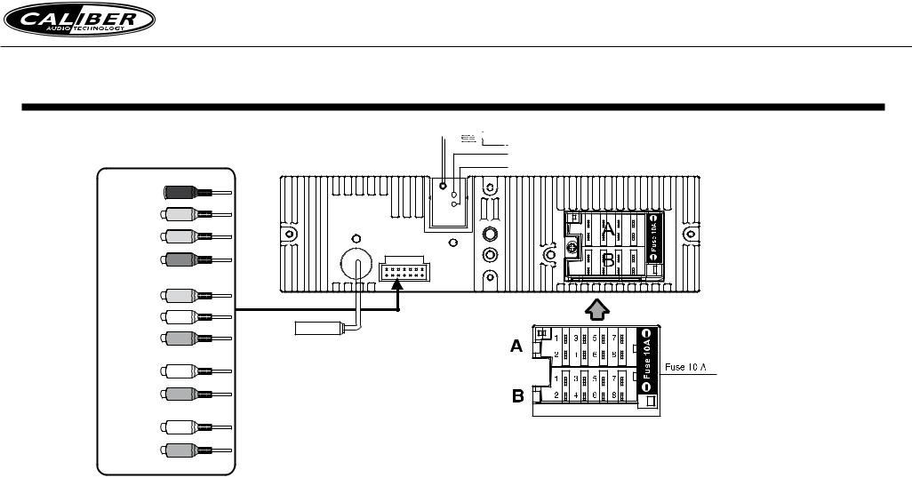
WIRING DIAGRAM
Steeringwheel
control
(3.5mm jack)
Camera IN
(yellow RCA)
Video OUT
(yellow RCA)
Sub OUT
(green RCA)
Video IN
(yellow RCA)
Audio IN
Left (white RCA)
Audio IN
Right (red RCA)
Audio OUT
F-left (white RCA)
Audio OUT
F-right (red RCA)
Audio OUT
R-left (white RCA)
Audio OUT
R-right (red RCA)


 Microphone IN (3.5mm jack) > only for RMD574BT
Parking brake (green)
Reverse (purple/white)
Radio
Antenna
Connector A |
Connector B |
||
1. |
Rear right speaker(+)/Purple |
1. |
- |
2. |
Rear right speaker(-)/Purple-Black |
2. |
- |
3. |
Front right speaker(+)/Grey |
3. |
- |
4. |
Front right speaker(-)/Grey-Black |
4. |
Battery 12V (+)/Yellow |
5. |
Front left speaker(+)/White |
5. Antenna power/Blue-White |
|
6. |
Front left speaker(-)/White-Black |
6. |
Panel light/Orange-White (optional) |
7. |
Rear left speaker(+)/Green |
7. ACC+/Red |
|
8. |
Rear left speaker(-)/Green-Black |
8. |
Ground/Black |

Manual RMD 574BT
WIRING DIAGRAM
General Wiring Notes:
Make sure You have a good chassis ground. Good ground connection will eliminate most electrical noise problems. A good chassis ground requires a tight connection to the .vehicle’s metal chassis. The area around the ground connection should be clean, bare metal without rust, paint, plastic, dust, or dirt for a good ground connection.
Black Ground
Connect to vehicle body/chassis. Make sure you have a good chassis ground. This will eliminate most electrical noise form the motor and alternator. A good chassis ground requires a tight connection to ground. The area should be free from rust, paint or any form of dirt.
Red Ignition
Connect to car ignition switch for main power supply of the unit.
Yellow Memory Backup
Connect to electrical terminal always supplied with power regardless of ignition switch position.
Blue-White Remote
Connect to Auto-antenna or power amp control wire/remote connection. Maximum current 300mA 12VDC. (Low Current)
Green (Hand Brake - Ground)
Connect this wire to the hand brake wire of your car so that the display will be on only when the car is fully stopped.
Purple-White (Rear Gear - VCC)
Connect this wire to the rear gear wire of your car so that the backup camera function can be activated when you car is in reverse gear.
Orange-White (Panel Light)
Connect the this wire to the car light switch so that the front panel illumination will be on when the car light switch is turned on.
Various outputs (Refer to the wiring diagram)
Refer to the wiring diagram for the connection details.
Speaker Wiring Notes:
Follow the above wiring diagram to install the head unit with new or existing speakers.
1.This unit is designed for use with four (4) speakers with impedance between 4 Ohms to 8 Ohms.
2.An Impedance load of less than 4 Ohms could damage the unit.
3.Never bridge or combine the speaker wire outputs. When not using four speakers, use electrical tape to tape the ends of the unused speaker outputs to prevent a short circuit.
4.Never ground the negative speaker terminals to chassis ground.
 Loading...