


PRECAUTION
CAUTION |
|
RISK OF FIRE OR ELECTRIC |
|
|
|
WARNING: TO REDUCE THE |
|
|
! |
SHOCK, DO NOT EXPOSE |
|
RISK OF ELECTRIC SHOCK |
|||
THIS APPLIANCE TO RAIN OR |
|||
DO NOT OPEN |
|
MOISTURE. |
|
|
|
CAUTION: TO REDUCE THE RISK OF ELECTRIC SHOCK, DO NOT REMOVE COVER (OR BACK). NO USER SERVICEABLE PARTS INSIDE. REFER SERVICING TO QUALIFIED SERVICE PERSONNEL.
The lightening flash with arrowhead symbol, within an equilateral triangle, is intended to alert the user to the presence of uninsulated dangerous voltage within the products enclosure that may be of sufficient magnitude to constitute a risk of electric shock to persons.
The exclamation point within an equilateral triangle is intended to alert user to
!the presence of important operating and maintenance (servicing) instructions in the literature accompanying the appliance.
CLASS 1 LASER PRODUCT
Laser product symbol: located on the rear panel of the unit, indicate this player is a class laser product, only use weak laser and no hazardous radiation outside of the unit.
1.Read through this instruction manual before installation and use.
2.Do not open the cover or touch any of the components exposed out of the unit, only for qualified technicians.
3.Clear the panel and case with soft dry cloth only, do not apply any kind of thinner, alcohol or sprays.
4.The apparatus shall not be exposed to dripping or splashing and that no objects filled with liquids, such as vases, shall be placed on the apparatus .

Contents |
|
|
1. Before Operation........................................................................................... |
3 |
|
1.1 |
Glossary................................................................................................ |
3 |
1.2 |
Precautions............................................................................................ |
3 |
1.3 Maintenance and Cleaning of Discs............................................. |
.............4 |
|
1.4 Battery Information of the Remote Control................................................. |
4 |
|
1.5 |
Remote Control Description..................................................................... |
5 |
1.6 Locations and Names of Controls on or in the unit...................................... |
6 |
|
1.7 |
Wires Connection Description.................................................................. |
7 |
1.8 |
Unit Installation....................................................................................... |
8 |
2. Common Operation........................................................................................ |
9 |
|
3. Radio Operation........................................................................................... |
11 |
|
4. Disc, USB and Card Operation...................................................................... |
14 |
|
4.1 Load/unload Disc, USB or Card............................................................... |
16 |
|
4.2 Pause Playback..................................................................................... |
16 |
|
4.3 Stop Playback ....................................................................................... |
16 |
|
4.4 Select Chapter/Track with the >>|/|<< Buttons.......................................... |
16 |
|
4.5 Select Chapter/Track with the Number Buttons......................................... |
16 |
|
4.6 Select Chapter/Track with the Root/PBC Menu......................................... |
16 |
|
4.7 Playback with Speed.............................................................................. |
17 |
|
4.8 Playback with Slow Speed...................................................................... |
17 |
|
4.9 Display Still Frame Step by Step............................................................. |
18 |
|
4.10 Playback Repeatedly........................................................................... |
18 |
|
4.10.1 One/All Repeat................................................................................. |
18 |
|
4.10.2 A-B Repeat....................................................................................... |
18 |
|
4.11 Playback in Scan Mode......................................................................... |
19 |
|
4.12 Playback from a specified Chapter/Track............................................... |
19 |
|
4.13 Playback in Random............................................................................. |
19 |
|
4.14 Playback in Different View-Angle........................................................... |
19 |
|
4.15 Playback in Zoom Mode........................................................................ |
19 |
|
4.16 Change the Caption Language..................................................... |
.........20 |
|
4.17 Change the Audio Language................................................................. |
20 |
|
4.18 Look over the Playback Status.............................................................. |
20 |
|
4.19 Program Playback............................................................................... |
21 |
|
4.20 Playback IMAGE files.......................................................................... |
21 |
|
4.21 Playback MP4 files.............................................................................. |
22 |
|
4.22 ESP and ID3 Function.......................................................................... |
22 |
|
4.23 DVD System Menu Setup Operation...................................................... |
22 |
|
* |
Parental Control.................................................................................. |
26 |
* |
Region Code....................................................................................... |
27 |
5.Blue Tooth Hands-free System...................................................................... |
28 |
|
6. Trouble Shooting......................................................................................... |
30 |
|
7. Specification................................................................................... |
Back cover |
|

1.Before Operation
1.1Glossary
PBC (playback control)
This is a signal(menu) recorded on the disc with SVCD or VCD2.0 format used for the playback control. For discs containing PBC, It can playback interactive software with the menu displayed on monitor screen.
If the disc contains still images, it can playback high definition still images.
Title
Generally, the title is the important part of DVD disc. for example, the theme part of movie is title1,the part describing how to make movie is title 2,the cast is title 3,etc. Every title contains a serial number that is easy to look up.
Chapter
A title can be divided into several blocks, so that every block can be operated as a unit,the unit is called a chapter.The chapter contains at least 1 unit.
Track
This is the biggest component of VCD. Generally,every song of karaoke disc is a track.
1.2 Precautions
Safety
1.Power Source: The unit should be connected to power supply only of the type described in the operating instructions or as marked on the unit.
2.The unit is designed for negative terminal of the battery which is connected to the vehicle metal. Please confirm it before installation.
3.Do not allow the speaker wires to be shorted together when the unit is switched on. Otherwise it may overload or burn out the power amplifier.
4.Do not install the detachable panel before connecting the wire.
Environment
1.Do not use this unit when water and moisture is near it.
2.If moisture forms inside the Lens, it may not operate properly. To correct this problem, wait about one hour for the moisture to evaporate.
3.If the car interior is extremely hot, do not use the player until the car has been driven for a while to cool off the interior.
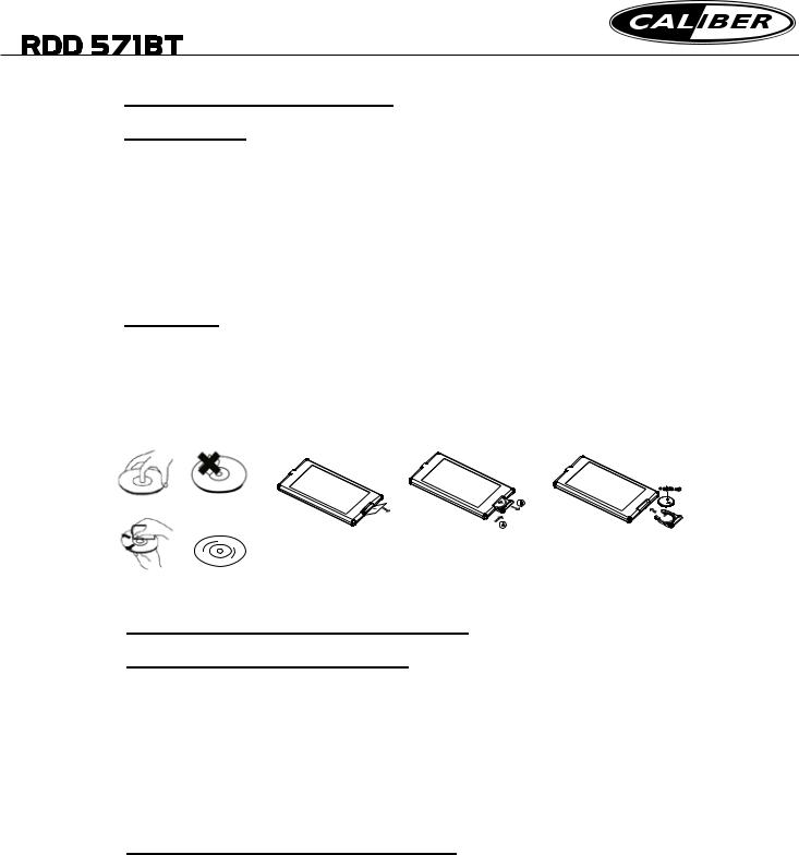
1.3 Maintenance and Cleaning of Discs
Disc Maintenance
1.To keep the disc clean, handle the disc by its edge, do not touch the disc surface of the play side.
2.Do not stick paper or tape on the disc. If there is glue(or dirt) on the disc surface, wipe it before using.
3.Do not expose the disc to direct sunlight, or nearby heat sources such as caliduct, or leave it in a car parked in direct sunlight where there can be a considerable rise in temperature.
4.Put the disc inside disc case to keep temperature after finishing playback.
Disc Cleaning
1.Before playing, wipe the disc with a clean lint. wipe the disc outwards from the disc center.
2.Do not use petrel, thinner. commercially cleaner or anti-static spray can damage the unit.
+
 side up
correct |
wrong |
|
B |
|
|
|
A |
|
Fig.1 |
Fig.2 |
Fig.3 |
correct wrong
1.4 Battery Information of the Remote Control
Replace Battery in the Remote Control:
1.Before using the remote control for the first time, pull the insulating sheet out of the remote control as the direction indicated by the arrow.(see fig.1)
2.Press the movable block hold as the direction indicated by the A arrow (See fig.2), then pull the battery holder out of the remote control as the direction indicated by the B arrow(see fig.2).
3.Replace the old battery by a new battery with (+) polarity side upward. (See fig.3).
4.Insert the battery holder to the original position in remote control. (See fig.3).
Note about the Battery of the Remote Control:
1.Improper use of battery may cause overheating or explosion. so that Result in injury or fire .
2.Battery leakage may cause damage to the remote control(Battery Life: 6 months with normal use in normal room temperature). 3.Do not short the battery.
4.Do not throw the battery into the fire.
5.To avoid the risk of accident, keep the battery out of reach of children.
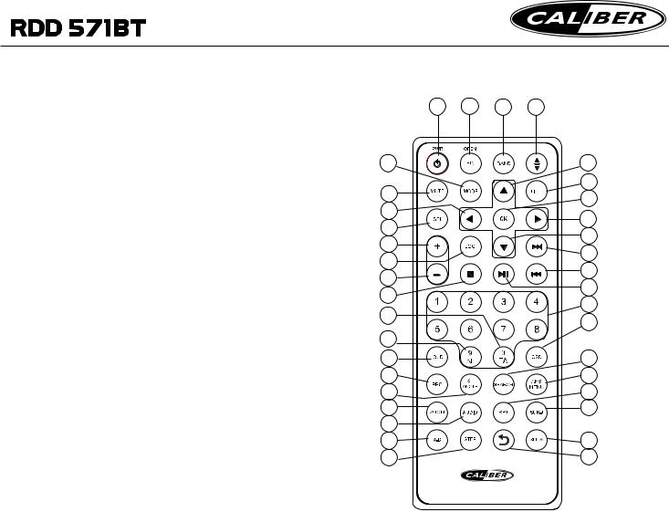
1.5 The Remote Control Description
1.ANG BUTTON
2.TITLE BUTTON
3.POWER BUTTON
4.^ BUTTON
5.>>| BUTTON
6.> BUTTON
7.|<< BUTTON
8.v BUTTON
9.SEL BUTTON
10.PLAY/PAUSE BUTTON
11.NUMBER(0~9) BUTTONS
12.OSD BUTTON
13.LOC BUTTON
14.MODE BUTTON
15.APS/MENU BUTTON
16.SEARCH BUTTON
17.SUBTITLE BUTTON
18.RPT BUTTON
19.SLOW BUTTON
20.BACK BUTTON
21.ANGLE/ST BUTTON
22.ZOOM BUTTON
23.STEP BUTTON
24.LOUD BUTTON
25.A-B BUTTON
26.AUDIO BUTTON
27.OPEN/EQ BUTTON
28.PBC BUTTON
29.MUTE BUTTON
30.STOP BUTTON
31.VOLUMEBUTTON
32.< BUTTON
33.OK BUTTON
34.VOLUME+ BUTTON
35.BAND BUTTON
36.TA BUTTON
37.AF BUTTON
3 |
27 |
35 |
1 |
14 |
|
|
4 |
29 |
|
|
2 |
|
|
33 |
|
32 |
|
|
|
|
|
6 |
|
9 |
|
|
|
|
|
8 |
|
34 |
|
|
|
|
|
5 |
|
13 |
|
|
|
|
|
7 |
|
31 |
|
|
|
|
|
10 |
|
30 |
|
|
|
|
|
11 |
|
36 |
|
|
|
|
|
12 |
|
|
|
|
|
37 |
|
|
|
24 |
|
|
16 |
28 |
|
|
15 |
21 |
|
|
18 |
22 |
|
|
17 |
26 |
|
|
|
25 |
|
|
19 |
23 |
|
|
20 |

1.6 Locations and Names of Controls on or in the unit
5 |
21 |
20 |
19 |
18 |
17 |
16 |
15 |
22 |
|
|
|
|
|
|
|
|
|
|
|
|
BAND |
MIC |
|
|
|
|
|
|
|
|
|
1 |
OPEN |
MUTE |
|
|
|
|
|
|
|
|
|
|
|
|
|
|
|
|
|
|
|
|
|
|
MODE |
|
|
|
|
|
|
|
|
|
REL |
|
|
1 |
2 |
INT |
3 |
RPT |
4 |
RDM |
5 |
6 |
|
|
|
|
6 |
4 |
3 |
2 |
7 |
8 |
9 |
10 |
11 |
12 |
13 |
14 |
Front Panel
|
|
23 |
24 |
|
|
|
|
The Front Face after removing front panel |
|
1. OPEN button |
13.USB Jack |
|||
2. POWER/MUTE button |
14. REL button |
|||
3. MODE button |
15. AV IN socket |
|||
4.VOL KNOB & SEL button |
16.IR Remote Sensor |
|||
5. |
|
|
button |
17.Disc Slot |
|
||||
|
||||
6. |
|
|
button |
18. Monitor |
|
|
|||
|
|
|||
7. PLAY/PAUSE/1 button |
19.Small LCD Screen |
|||
8.INT/2 button |
20.Microphone |
|||
9. RPT/3 button |
21.BAND button |
|||
10.RDM/4 button |
22.EJECT button |
|||
11 5 button |
23.SD/MMC Card Slot |
|||
12. 6 button |
24. RESET button |
|||
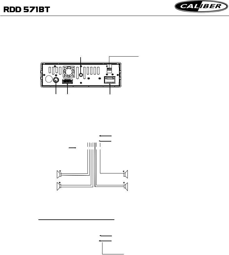
1.7 Wires Connection Description
The Description of the Input/Output Interface of the Rear Cabinet
BT Microphone in
Fixing Screw Bolt
Radio Antenna Wiring Connecting Socket 2 |
Wiring Connecting Socket 1 |
1.Parking wire must be connected. And the parking brake must be engaged in order for the monitor to work.
2.Use the clip end of the Ground Wire provided by manufacturer to connect Mounting Screw, using the other end of the Ground Wire to connect the negative pole of the power source. Otherwise, the video on screen maybe flashes.
Description of the Wiring Diagram for Socket 1
|
|
|
|
|
|
|
|
|
|
|
|
|
|
|
|
|
|
WIRING CONNECTING SOCKET 1 |
|||||||||||
|
|
|
|
|
|
|
|
|
|
|
|
|
|
|
|
|
|
||||||||||||
ISO CONNECTOR |
|
|
|
|
|
|
|
|
|
WIRING CONNECTING PLUG 1 |
|||||||||||||||||||
|
|
|
|
|
|
|
|
|
|||||||||||||||||||||
|
|
|
|
|
|
|
|
|
|||||||||||||||||||||
|
|
|
|
|
|
|
|
|
|
|
|
|
|
|
|
|
|
|
|
|
|||||||||
YELLOW |
|
|
|
|
|
|
|
|
|
|
|
SUBWOOFER OUTPUT |
|||||||||||||||||
|
|
|
|
|
|
|
|
|
|
||||||||||||||||||||
|
|
|
|
|
|
|
|
|
|
|
|||||||||||||||||||
MEMORY B+ |
|
|
|
|
|
|
FUSED |
|
|
|
|
|
|
|
|
|
|
|
|
|
|
|
|
|
GREEN |
||||
BLACK(GND) |
|
|
|
|
|
|
FILTER |
|
|
|
|
|
|
|
|
|
|
|
|
|
|
|
|
||||||
|
|
|
|
|
|
BOX 1A |
|
|
|
|
|
|
|
|
|
|
|
|
|
|
|
|
|
|
|
|
|
RED(R) |
|
RED |
|
|
|
|
|
|
|
|
|
|
|
|
|
|
|
|
|
|
|
|
|
|
|||||||
|
|
& 10A |
|
|
|
|
|
|
|
|
GRAY |
|
|
|
|
|
|
|
|
|
|||||||||
IGNITION SWITCH |
|
|
|
|
|
|
FUSES |
|
|
|
|
|
|
|
|
|
RCA OUTPUT |
|
|
|
|
|
|
|
|
|
WHITE(L) |
||
BLUE AUTO ANT |
|
|
|
|
|
|
|
|
|
|
|
|
|
|
|
|
|
|
|
|
|
|
|
|
|
|
|
||
|
|
|
|
|
|
|
|
|
|
|
|
|
|
|
|
|
|
|
|
|
|
|
|
|
|
|
|
||
FRONT |
+ |
|
|
|
WHITE |
|
|
|
|
|
GRAY |
+ |
|
|
|
|
FRONT |
||||||||||||
|
|
|
|
|
|
|
|
|
|
|
|
|
|
|
|
|
|
|
|
|
|
|
|
|
|
|
|
|
|
LEFT |
|
|
|
|
|
|
WHITE / BLACK |
|
|
|
|
GRAY / BLACK |
|
|
|
|
|
RIGHT |
|||||||||||
|
|
|
|
|
|
|
|
|
|
|
|
|
|
||||||||||||||||
|
|
|
|
|
|
|
|
|
|
|
|
|
|
|
|
|
|
|
|
|
|
|
|
||||||
SP |
+ |
|
|
|
GREEN |
|
|
|
|
|
VIOLET |
+ |
|
|
|
SP |
|||||||||||||
REAR |
|
|
|
|
|
GREEN / BLACK |
|
|
VIOLET / BLACK |
|
|
|
|
|
|
|
REAR |
||||||||||||
|
|
|
|
|
|
|
|
|
|
|
|
|
|
|
|
|
|||||||||||||
|
|
|
|
|
|
|
|
|
|
|
|
|
|
|
|
|
|
||||||||||||
NOTES:
1.Only speakers with 4 ohms impedance may be used.
2.Ensure that the blue auto antenna cable does not make contact with any ground connection.
Description of the Wiring Diagram for Socket 2
|
|
|
|
|
|
|
|
|
|
|
|
|
WIRING CONNECTING SOCKET 2 |
||
|
|
|
|
|
|
|
|
|
|
|
|
|
|||
|
|
|
|
|
|
|
|
|
|
|
|
|
WIRING CONNECTING PLUG 2 |
||
|
|
|
|
|
|
|
|
|
|
|
|
|
|||
|
|
|
|
|
|
|
|
|
|
|
|
|
|||
YELLOW |
|
|
REAR VIEW CAMERA |
|
|
REVERSAL LINE |
|||||||||
|
|
|
BLACK |
|
|
|
|
|
WHITE |
||||||
YELLOW |
|
|
|
|
|
|
|
PARKING LINE |
|||||||
|
|
|
|
|
VIDEO LINE OUT |
|
|||||||||
|
|
|
|
|
|
|
|
|
|||||||
|
|
|
|
|
|
|
|
|
|
|
|
|
|
|
GREEN |
|
|
|
|
|
|
|
|
|
|
|
|
|
|
||
|
|
|
|
|
|
|
|
|
|
|
|
||||
YELLOW |
|
|
|
|
|
|
|
|
|
|
|
|
|||
|
|
|
|
|
|
|
|
|
|
|
|
|
|
|
|
Description of Connecting the Parking Brake Line to the Parking Brake System Built in the Car
Parking brake 


|
Parking brake line(green) |
Parking brake switch |
To metallic body or chassis of the car |
(inside the car) |
|
NOTE: after connecting the Parking Line, the video on the small monitor of the front panel will be display only after braking the car.
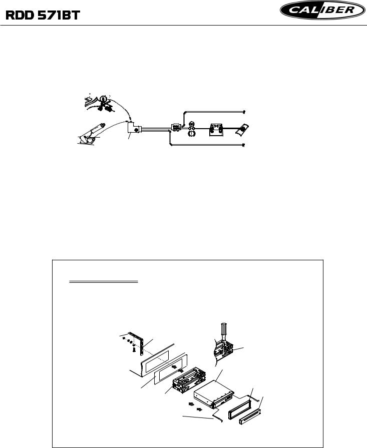
1.8 UNIT INSTALLATION
INSTALLATION INSTRUCTIONS
THE UNIT IS INSTALLED TO BE AN ANTI-THEFT ONE. THE CHASSIS
OF THE UNIT WEARS A SLIDING METAL HOUSING. PLEASE DO THE
CONNECTION OF THE POWER, SPEAKERS AND ANTENNA ACCORDING
TO THE REQUIREMENT OF THE INSTRUCTION BOOK , THEN INSTALL
THE SLIDING METAL HOUSING IN THE CAR AS FOLLOWS.
|
TO BOOST UP THE CAPABILITY OF |
|
ANTI-JAMMING, PLEASE FIX THE |
|
METAL STRAP ON THE METAL |
|
CONNECTED TO THE BOTTOM |
METAL STRAP |
BRACKET OF THE CAR. |
SELECT THE PROPER TAB FOR FIXING THE SLIDING METAL HOUSING.
UNIT CHASSIS
PLASTIC TRIM OUT
DASH BOARD
SLIDING METAL HOUSING |
FRONT PANEL |
TO DRAW THE CHASSIS OUT OF
THE SLIDING METAL HOUSING,
INSERT THE LEFTAND RIGHT KEY
PLATES INTO THE RIGHT POSITION
OF THE 2 SIDES OF CHASSIS.
2. Common Operation
1.To turn on/off the unit
In power off mode, briefly press any button on the unit or remote control to turn on the unit.
In power on mode,press and hold the POWER button on the front panel or briefly press the POWER button on the remote control to turn off the unit.
2.To slide the monitor of the Car Audio System out of/into the chassis Pressing the OPEN button can slide the monitor of the Car Audio System out of the chassis or slide it into the chassis.
3.To select an optimal angle of the monitor of the Car Audio System To select an optimal angle of the monitor of the Car Audio System, press the ANG button on the remote control repeatedly.
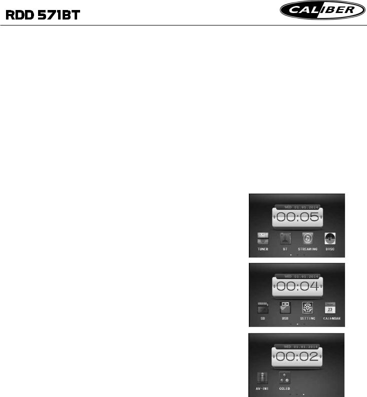
4.To select function mode
Press the MODE button to select TUNER, DISC (After inserting a disc), USB(After inserting a USB storage), SD(After inserting a card),BLUETOOTH, STREAMING and AV IN1 mode.
During playback, tapping the  icon after popping up Keyboard interface can pop up Mode Menu as right. tap the icons
  at the bottom to select Mode Menu interfaces. Then tap the icon in it to select your desired mode.
5. To adjust sound level
Rotating the VOL knob or press or hold the + or - button on the remote control to directly adjust the volume level.
6.To mute sound
Press the MUTE button on the remote control or POWER button on the front panel to turn on/off MUTE mode.
7.To display the clock time
In the Mode Menu interface the date and clock time display on the screen all the time.
During playback,Press the CLK button on the remote control to display clock time on the screen.
Mode Menu interface 1,2,3
8.To select a desired EQ mode
Press the EQ button on the remote control to select one of the preset music equalizer curves: ROCK, POP, CLASS, EQ OFF. The sound effect will be changed.
9.To turn on/off LOUD mode
Press the LOUD button to turn on/off LOUD mode.
When turning on LOUD mode, it will enhance bass level immediately when bass is not enough.
10. To reset the player
When the monitor displays wrongly or some buttons are not available or sound is distorted, press the RESET button to restore the distorted program.
11.To do setup |
|
|
To do setup, tap the |
icon in the Mode Menu to turn to |
|
SETTING interface as right. |
|
|
In the interface, select one of GENERAL, TIME,LANGUAGE |
||
AUDIO, VIDEO , CALIBRATE by tapping them, then set |
||
them by tapping the direction icons |
on the screen. |
|
GENERAL ----Logo:chang the picture of opening the unit. |
||
----Radio region:select the region your desired to |
||
listen to. |
|
|
----RDS Setting: Set the RDS function on or off. TIME---------- for adjusting the year,date and the clock time.
Note: You can also adjust the date in the CALENDAR interface. Firstly adjusting the year and month by tapping the icons 
 ,secondly press and hold the date number to select the date.
LANGUAGEfor adjusting the DISC Menu,DISCAudio, and DISC Subtitle language.
AUDIO-------- for adjusting the DBAS,MBP,Loud,EQ. Camera VOL ,BT VOL.
VIDEO-------- for adjusting theAspect ration,Brightness, Contrast,Saturation and Hue.
CALIBRATEInputting the password 888888 to enter the mode, then calibrate the TFT display by tapping each center of the moving cross cursor until the word “OK” is displayed on the screen.
General setting interface
Calendar interface
Calibrate setting interface
 Loading...