

Page 1

Type BBS-11
Safety ingold socket with Asepto sampling system
Sicherheits-Ingoldstutzen mit Asepto Probeentnahme
Raccord Ingold de sécurité avec prélèvement d'échantillons Asepto
Bedienungsanleitung
Manuel d‘utilisation
Operating Instructions
www.burkert.com
International address
www.burkert.com → Bürkert → Company → Locations
Manuals and data sheets on the Internet : www.burkert.com
Bedienungsanleitungen und Datenblätter im Internet: www.buerkert.de
Instructions de service et fiches techniques sur Internet: www.buerkert.fr
© 2013 Bürkert Werke GmbH
Operating Instr uctions 1401/01_EU-ML_00810326 / Original DE
Bürkert Fluid Control Systems
Sales Center
Christian-Bürkert-Str. 13-17
D-74653 Ingelfingen
Tel. + 49 (0) 7940 - 10 91 111
Fax + 49 (0) 7940 - 10 91 448
E-mail: info@de.buerkert.com
Page 2
2
1. THE OPERATING INSTRUCTIONS
The operating instructions contain important information.
• Read the instructions carefully and follow the safety instructions in
particular.
• Keep the instructions in a location where they are available to every
user.
• The liability and warranty for the product do not apply if the procedures in the instructions are not observed.
1.1. Symbols
→ designates a procedure which you must carry out.
Warning of injuries:
DANGER!
Immediate danger! Serious or fatal injuries.
WARNING!
Possible danger! Serious or fatal injuries.
CAUTION!
Danger! Moderate or minor injuries.
Warning of damage:
NOTE!
2. INTENDED USE
Non-authorized use of the Type BBS-11 may be dangerous to
people, nearby equipment and the environment.
• Type BBS-11 has been designed as a safety ingold socket for
sampling of equipment in the sterile area.
• Use according to the authorized data, operating conditions, and
conditions of use specified in the contract documents and operating instructions.
• Correct transportation, storage and installation, as well as careful use and maintenance are essential for reliable and faultless
operation.
• Use the product only as intended.
2.1. Restrictions
If exporting the products, observe any existing restrictions.
2.2. Definitions of terms
The term "product" used in these instructions always refers to Type
BBS-11.
english
3
4. GENERAL INFORMATION
4.1. Contact address
Germany
Bürkert Fluid Control Systems
Sales Center
Christian-Bürkert-Str. 13-17
D-74653 Ingelfingen
Tel. + 49 (0) 7940 - 10 91 111
Fax + 49 (0) 7940 - 10 91 448
E-mail: info@de.buerkert.com
International
Contact addresses can be found on the final pages of the printed
operating instructions. And also on the Internet at: www.burkert.com
4.2. Warranty
The warranty is only valid if the product is used as intended in
accordance with the specified application conditions.
4.3. Information on the Internet
The operating instructions and data sheets for Type BBS-11 can be
found on the Internet at: www.burkert.com
3. BASIC SAFETY INSTRUCTIONS
These safety instructions do not take into account any contingencies and
events which may arise during the installation, operation and maintenance
of the product.
Danger – high pressure and discharge of medium!
• Before loosening the nuts or screws, always turn off the pressure
and relieve the lines/containers.
• Wear protective equipment if media is hazardous.
General hazardous situations
• Do not make any internal or external changes to the product.
• Ensure that the system cannot be activated unintentionally.
• Installation and maintenance work may be carried out only by
authorized technicians with the appropriate tools.
• The product may be operated only when in perfect condition and in
consideration of the operating instructions.
• As far as inspection, maintenance and repairs are concerned,
observe national provisions of the country in which the connection
elements are installed.
• The general rules of technology apply to application planning and
operation of the product.
english
4
5. TECHNICAL DATA
5.1. Conformity
Type BBS-11 conforms to the EC directives according to the EC
Declaration of Conformity.
5.2. Standards (if applicable)
The applied standards which are used to demonstrate compliance with
the EC Directives are listed in the EC type test certificate and/or the
EC Declaration of Conformity.
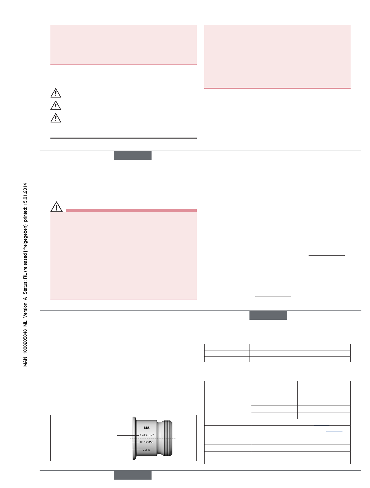
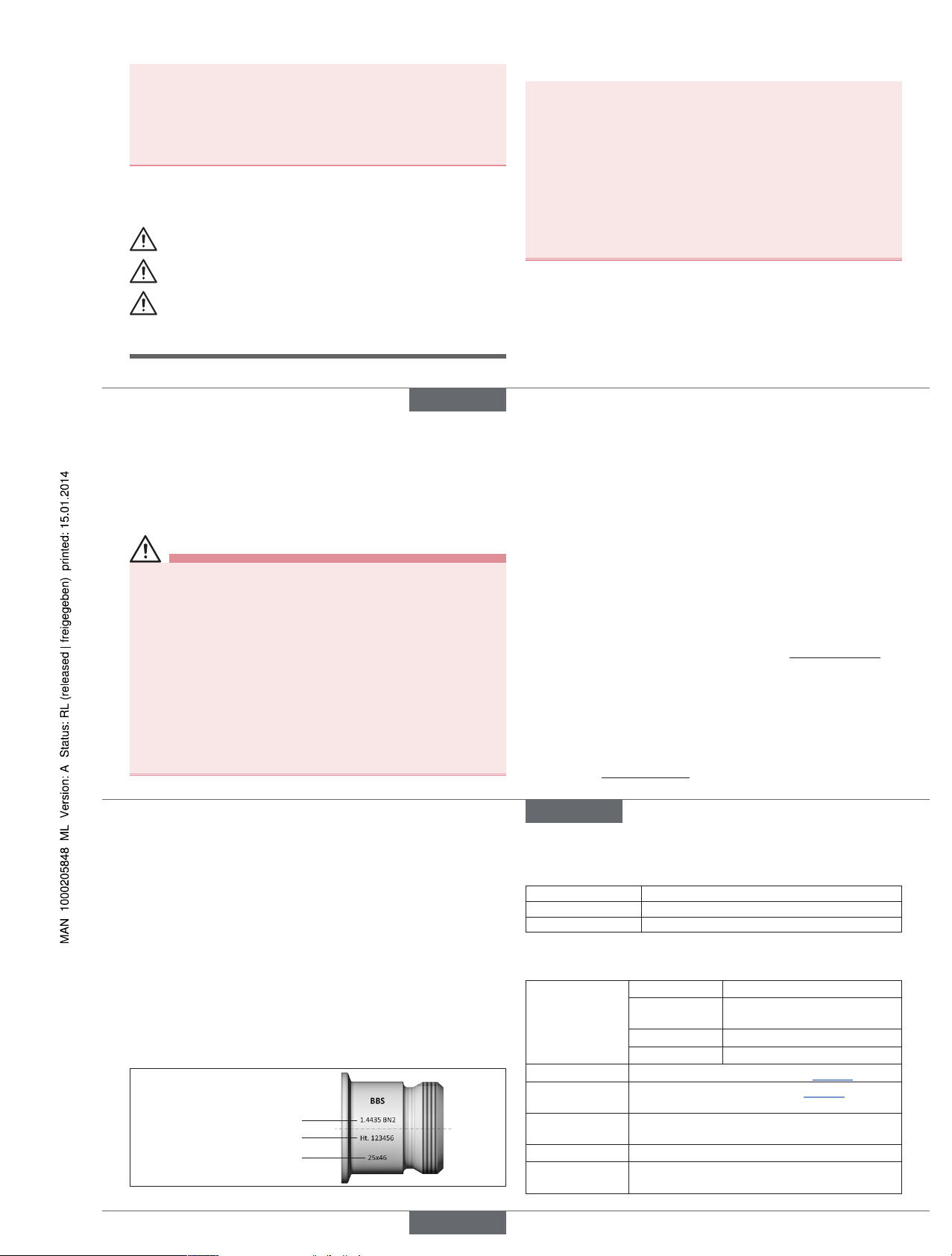
5.3. Identification
Information on material, pipe and connection dimensions can be found
on the stamping on the product. The identification number of the
product can be found on the supplied 3.1 certificate.
Material
Material batch number
Insert dimension
Fig. 1: Example of identification of the product
5.4. Sealing materials
Seal material Operating temperature
EPDM –40 °C to 90 °C, briefly up to 140 °C
FEP -60 °C to 160 °C, briefly up to 205 °C
Tab. 1: Sealing materials BBS-11
5.5. General technical data
Material
comes into contact
with medium
Stainless steel 1.4435
BN2 (316L)
does not comes into
contact with medium
Stainless steel 1.4401
or equivalent
Diaphragm silicone
O-ring EPDM/FEP
Pipe dimensions
see identification on product (“Fig. 1”)
Permitted application temperature
Depending on sealing material, see “Tab. 1”
Ambient temperature –20 °C to +80 °C
Media Fluids
Operating pressure -1 to +16 bar (depending on temperature and
size, see data sheet)
english
Type BBS-11
Page 3
5
6. ASSEMBLY
WARNING!
Danger – high pressure and discharge of medium!
• When working on the product or the system, always switch off the
pressure and relieve the lines/containers.
• Wear protective equipment if media is hazardous.
Risk of injury from improper assembly!
• Installation must only be carried out by authorized technicians and
with the appropriate tools!
• Secure system from unintentional activation.
6.1. Welding in the safety ingold socket
NOTE!
Leak due to damaged sealing elements!
• Do not weld in the assembled product. It is essential to remove
the plug before welding and protect it from dust, flying sparks and
other influences!
Leak due to damaged sealing contour!
• To ensure the sealing function, protect the sealing contour during
installation, welding and cleaning procedures.
• When reworking the welded-in ingold socket, the sealing contour
must not be damaged.
• The inner diameter Di of ingold socket has to be machined
to 25H7 respectively 40H7 after welding.
• Welding in and reworking of the safety ingold socket may be
carried out only by adequately trained professionals!
→ Connect the parts positively in a protective gas shield.
When cleaning the weld seam by grinding or acid cleaning, observe
the following before assembling the connection:
• Carefully remove all grinding dust and acid-cleaning residue.
• Do not damage the label.
• There must be no material abrasion on the sealing edges. Material
abrasion will result in sharp-edged sealing contours and a damaged
seal.
• Check sealing contour for damage.
We recommend preparing a welding report.
english
6
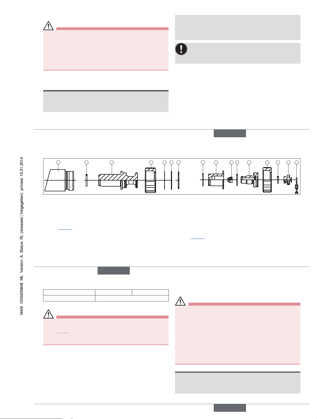
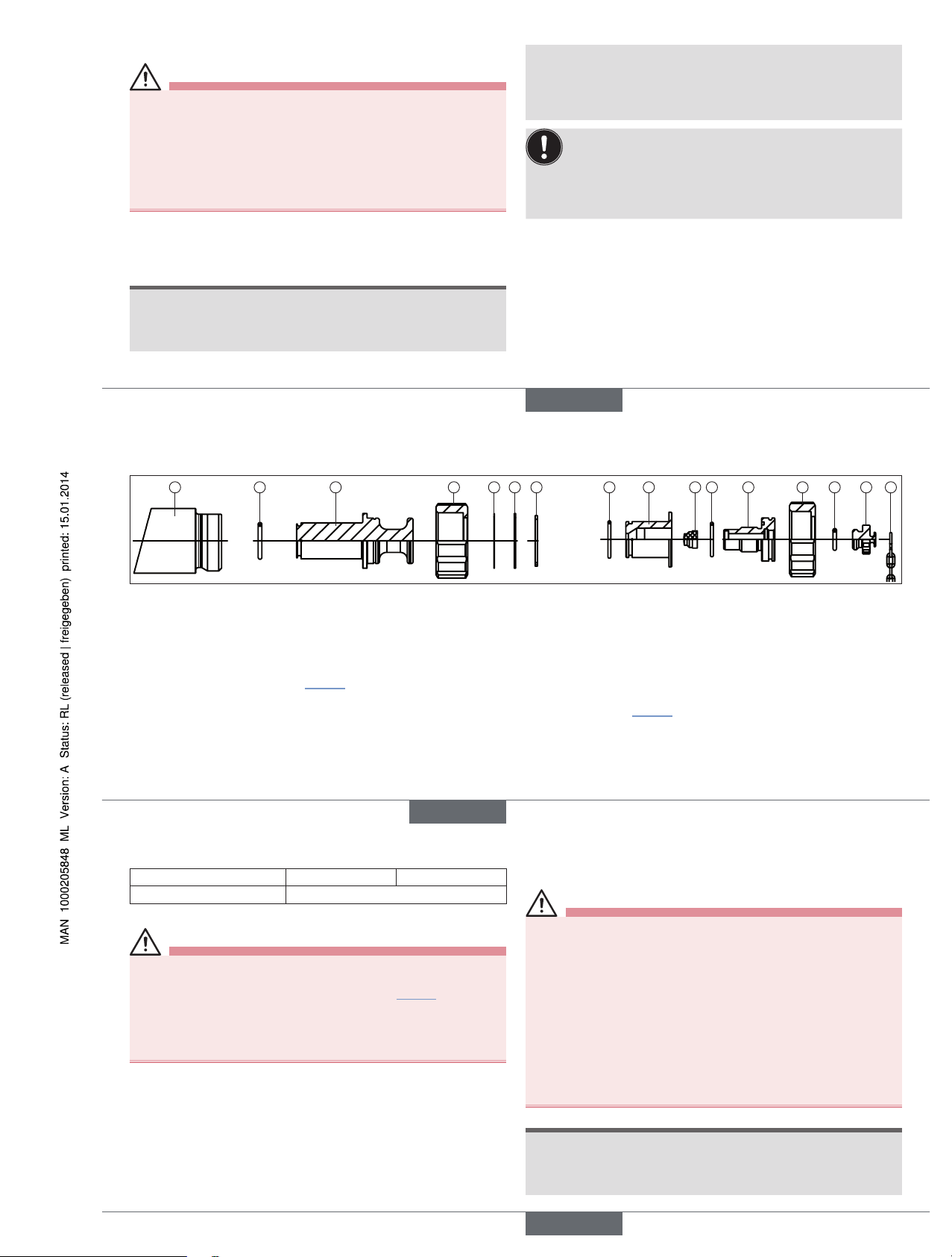
6.2. Assembly of dummy plug and Asepto sampling socket
1 2 3 4 5 6 7 2 8 9
10 11 12 13 14
4
Dummy plug Asepto sampling socket
Fig. 2: Assembly of dummy plug and Asepto sampling socket Type BBS-11
→ Push the diaphragm (9) forward to the limit stop in the sampling
socket (11) and screw the socket tightly to the sampling ingold (8).
Attention: This screw connection may not be loosened during
operation or when under pressure!
→ Push this assembly into the welded-in socket (1) and screw
down securely, using the union nut (4). Observe tightening torque
(see “Tab. 2”). Attention: This screw connection may not be
loosened during operation or when under pressure!
→ Screw the locking element (13) onto the sampling socket. This is
the only screw connection that may be opened during operation
(for the purpose of sampling). The chain (14) prevents that the
locking element gets lost.
Dummy plug
→ Ensure the correct position of the O-ring (2) on the dummy ingold
(3). Screw the dummy ingold into the welded-in ingold socket
(1) to lock it, using the union nut (4). Observe tightening torque
(see “Tab. 2”).
This way, sampling is no longer possible.
Shim ring (5), spacer ring (6) and retaining ring (7) have already been
mounted in the supplied state and should not be removed.
Asepto sampling socket
→ Before screwing the ingold socket in, ensure the presence and
correct position of the O-rings (2, 10, 12).
english
7
Orifice (DN) 25 40
Tightening torque (Nm)
hand-tight
Tab. 2: Tightening torque of union nut Type BBS-11 ingold socket
WARNING!
Danger – high pressure and discharge of medium!
• During operation and/or existing pressure, only the sampling cap
(see “Fig. 2”, sketch on the far right with chain) may be opened. It
can be opened with just a few turns.
• All other screw connections may not be loosened in this state.
6.3. Disassembly
Disassembly is in reverse sequence to assembly.
7. START-UP
WARNING!
Risk of injury from improper operation!
Improper operation may result in injuries as well as damage to the
product and the surrounding area.
• Before start-up, ensure that the operating personnel are familiar
with and completely understand the contents of the operating
instructions.
• Observe the safety instructions and intended use.
• Only adequately trained personnel may start up the equipment/the
product.
• Following assembly, ensure a controlled restart.
• When starting up the equipment, ensure that no unauthorized voltage increases and pressure surges can occur.
NOTE!
Replace wearing parts in time
• It is the responsibility of the plant operator to ensure the durability
of the wearing parts. Observe that the wearing parts are replaced
in time.
english
Type BBS-11
Page 4
8
NOTE!
Dama
ge to the sealing elements when cleaning the system
.
• Clean the system preferably with a cleaning agent which does not
damage the sealing elements.
• Do not clean with wire brushes or machines which cause abrasion
of the surface.
• When using mechanical pipeline monitoring devices, ensure
that they do not damage the sealing elements (also the sealing
contour).
Damaged sealing elements must be replaced!
8. MAINTENANCE
WARNING!
Danger – high pressure and discharge of medium!
• Before loosening the nuts or screws, always turn off the pressure
and relieve the lines/containers.
• Wear protective equipment if media is hazardous.
• Nuts or screws may be retightened on pressurized lines/containers
only by technicians in consideration of special precautions.
• When shutting down the equipment, ensure that no unauthorized
voltage increases and pressure surges can occur.
• Following maintenance, ensure a controlled restart.
Have the product serviced regularly by technicians!
Inspection and maintenance work includes in particular monitoring and
ensuring the
• leak-tightness,
• identification,
• proper mode of operation of the safety and warning devices.
english
9
9. SPARE PARTS
CAUTION!
Risk of injury and/or damage by the use of incorrect parts!
Incorrect accessories and unsuitable spare parts may cause injuries
and damage the product and the surrounding area.
• Use only original accessories and original spare parts from Bürkert.
Spare parts are: O-rings, silicone diaphragm.
The spare parts can be ordered from your Bürkert sales office. The
order numbers for the spare part sets can be found on the corresponding data sheet on the Internet.
NOTE!
Replace wearing parts in time
• It is the responsibility of the plant operator to ensure the durability
of the wearing parts. Observe that the wearing parts are replaced
in time.
10. TRANSPORTATION, STORAGE,
DISPOSAL
NOTE!
Transport damage!
Inadequately protected sealing elements may be damaged during
transportation.
• Transport the product in a firmly assembled state, protected against
moisture and dirt, in shock-resistant packaging.
Incorrect storage may damage the product.
• Prevent the temperature from exceeding or dropping below the
permitted storage temperature.
• Store the product in a dry and dust-free location!
• Store O-rings and diaphragm dry and protected from UV radiation
and for not longer than 3 years.
• Storage temperature -40 to +80°C.
Damage to the environment caused by products contaminated
with media.
• Dispose of the product and packaging in an environmentally friendly
manner!
• Observe applicable disposal and environmental regulations.
english
Type BBS-11
Page 5
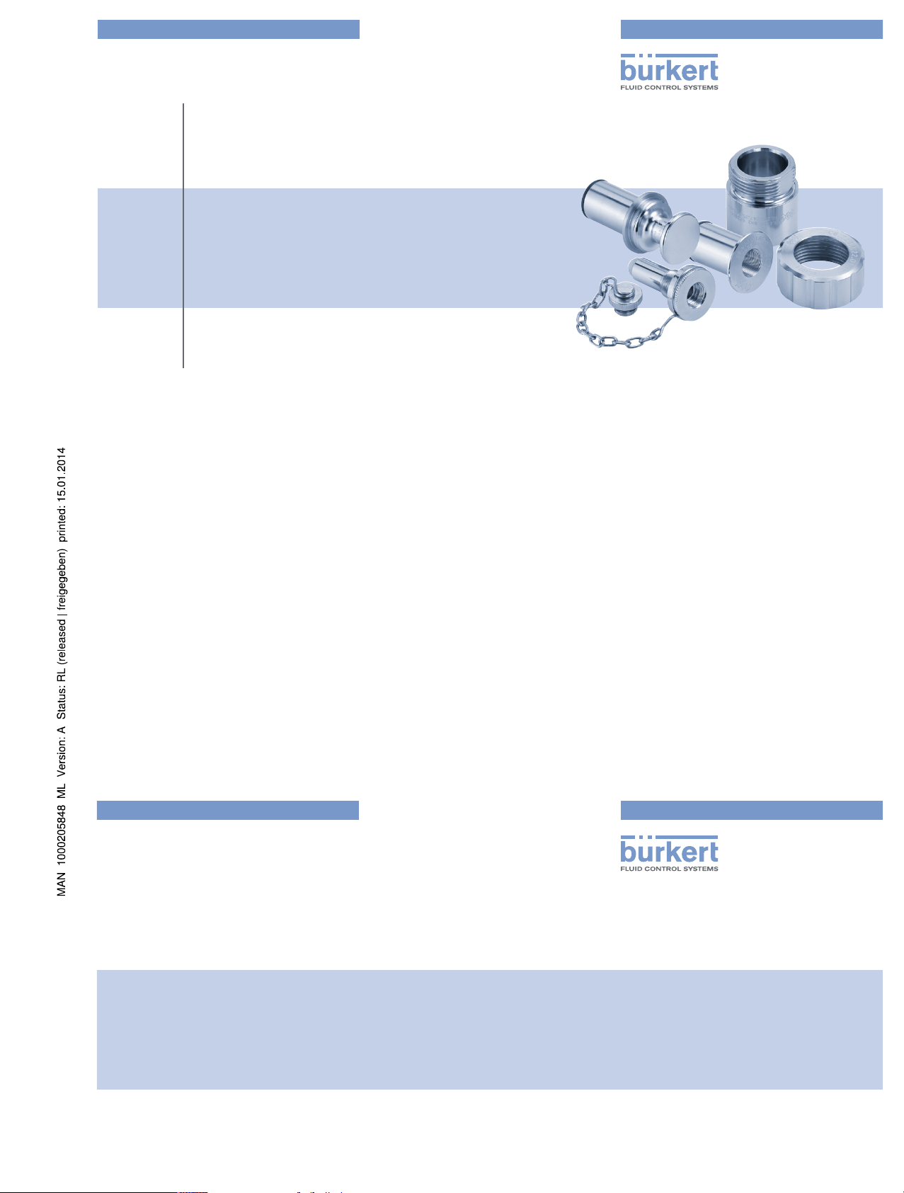
Type BBS-11
Safety ingold socket with Asepto sampling system
Sicherheits-Ingoldstutzen mit Asepto Probeentnahme
Raccord Ingold de sécurité avec prélèvement d'échantillons Asepto
Bedienungsanleitung
Manuel d‘utilisation
Operating Instructions
www.burkert.com
International address
www.burkert.com → Bürkert → Company → Locations
Manuals and data sheets on the Internet : www.burkert.com
Bedienungsanleitungen und Datenblätter im Internet: www.buerkert.de
Instructions de service et fiches techniques sur Internet: www.buerkert.fr
© 2013 Bürkert Werke GmbH
Operating Instr uctions 1401/01_EU-ML_00810326 / Original DE
Bürkert Fluid Control Systems
Sales Center
Christian-Bürkert-Str. 13-17
D-74653 Ingelfingen
Tel. + 49 (0) 7940 - 10 91 111
Fax + 49 (0) 7940 - 10 91 448
E-mail: info@de.buerkert.com
Page 6
10
1. DIE BEDIENUNGSANLEITUNG
Die Bedienungsanleitung enthält wichtige Informationen.
• Anleitung sorgfältig lesen und besonders die Hinweise zur Sicherheit
beachten.
• Anleitung so aufbewahren, dass sie jedem Benutzer zur Verfügung
steht.
• Haftung und Gewährleistung für das Produkt entfällt, wenn die
Anweisungen der Anleitung nicht beachtet werden.
1.1. Darstellungsmittel
→ markiert einen Arbeitsschritt, den Sie ausführen müssen.
Warnung vor Verletzungen:
GEFAHR!
Unmittelbare Gefahr! Schwere oder tödliche Verletzungen.
WARNUNG!
Mögliche Gefahr! Schwere oder tödliche Verletzungen.
VORSICHT!
Gefahr! Mittelschwere oder leichte Verletzungen.
Warnung vor Sachschäden:
HINWEIS!
2. BESTIMMUNGSGEMÄSSER
GEBRAUCH
Bei nicht bestimmungsgemäßem Gebrauch des Typs BBS-11
können Gefahren für Personen, Anlagen in der Umgebung und
die Umwelt entstehen.
• Typ BBS-11 ist als Sicherheits-Ingoldstutzen zur Probeentnahme für
Anlagen im sterilen Bereich konzipiert.
• Für den Einsatz die in den Vertragsdokumenten und der Bedienungsanleitung spezifizierten zulässigen Daten, Betriebs- und Einsatzbedingungen beachten.
• Voraussetzungen für den sicheren und einwandfreien Betrieb sind
sachgemäßer Transport, sachgemäße Lagerung und Installation
sowie sorgfältige Bedienung und Instandhaltung.
• Setzen Sie das Produkt nur bestimmungsgemäß ein.
2.1. Beschränkungen
Bei der Ausfuhr der Produkte gegebenenfalls bestehende Beschränkungen beachten.
2.2. Begriffsdefinition
Der in dieser Anleitung verwendete Begriff „Produkt“ steht immer für Typ
BBS-11.
deutsch
11
4. ALLGEMEINE HINWEISE
4.1. Kontaktadresse
Deutschland
Bürkert Fluid Control Systems
Sales Center
Christian-Bürkert-Str. 13-17
D-74653 Ingelfingen
Tel. + 49 (0) 7940 - 10 91 111
Fax + 49 (0) 7940 - 10 91 448
E-mail: info@de.buerkert.com
International
Die Kontaktadressen finden Sie auf den letzten Seiten der gedruckten
Bedienungsanleitung. Außerdem im Internet unter: www.burkert.com
4.2. Gewährleistung
Voraussetzung für die Gewährleistung ist der bestimmungsgemäße
Gebrauch des Produkts unter Beachtung der spezifizierten
Einsatzbedingungen.
4.3. Informationen im Internet
Bedienungsanleitungen und Datenblätter zum Typ BBS-11 finden Sie im
Internet unter: www.buerkert.de
3. GRUNDLEGENDE
SICHERHEITSHINWEISE
Diese Sicherheitshinweise berücksichtigen keine Zufälligkeiten und
Ereignisse, die bei Montage, Betrieb und Wartung des Produkts auftreten
können.
Gefahr durch hohen Druck und Mediumsaustritt!
• Vor dem Lösen von Muttern oder Schrauben unbedingt den Druck
abschalten und Leitungen/Behälter entleeren.
• Bei gefährlichen Medien Schutzausrüstung tragen.
Allgemeine Gefahrensituationen
• Am Produkt keine inneren oder äußeren Veränderungen vornehmen.
• Beachten, dass die Anlage nicht unbeabsichtigt betätigt werden kann.
• Installations- und Instandhaltungsarbeiten dürfen nur von autorisiertem Fachpersonal mit geeignetem Werkzeug ausgeführt werden.
• Das Produkt nur in einwandfreiem Zustand und unter Beachtung der
Bedienungsanleitung betreiben.
• Bei Inspektion, Wartung und Instandsetzung nationale Bestimmungen
des Aufstellungslands beachten.
• Für die Einsatzplanung und den Betrieb des Produkts die allgemeinen Regeln der Technik einhalten.
deutsch
12
5. TECHNISCHE DATEN
5.1. Konformität
Typ BBS-11 ist konform zu den EG-Richtlinien entsprechend der
EG-Konformitätserklärung.
5.2. Normen (soweit anwendbar)
Die angewandten Normen, mit denen die Konformität mit den EG-Richtlinien nachgewiesen wird, sind in der EG-Baumusterprüfbescheinigung
und/oder der EG-Konformitätserklärung nachzulesen.
5.3. Kennzeichnung
Angaben zu Material, Rohr- und Anschlussmaß sind auf das Produkt
geprägt. Die Identnummer des Produkts entnehmen Sie bitte dem mitgelieferten 3.1-Zeugnis.
Werkstoff
Materialchargennummer
Einschubmaß
Bild 1: Beispiel für die Kennzeichnung des Produkts
5.4. Dichtungsmaterialien
Dichtwerkstoff Betriebstemperatur
EPDM
–40 °C bis 90 °C, kurzzeitig bis 140 °C
FEP –60 °C bis 160 °C, kurzzeitig bis 205 °C
Tab. 1: Dichtungsmaterialien BBS-11
5.5. Allgemeine technische Daten
Material
mediumberührt Edelstahl 1.4435 BN2 (316L)
nicht
mediumberührt
Edelstahl 1.4401 oder Ähnliches
Membran Silikon
O-Ring EPDM/FEP
Rohrmaße
siehe Kennzeichnung auf Produkt („Bild 1“)
zulässige
Einsatztemperatur
je nach Dichtungsmaterial, siehe „Tab. 1“
Umgebungstemperatur
–20 °C bis +80 °C
Medien Fluide
Betriebsdruck –1 bis +16 bar (in Abhängigkeit von Temperatur
und Größe, siehe Datenblatt)
deutsch
Typ BBS-11
Page 7
13
6. MONTAGE
WARNUNG!
Gefahr durch hohen Druck und Mediumsaustritt!
• Bei Arbeiten am Produkt oder der Anlage unbedingt den Druck
abschalten und Leitungen/Behälter entleeren.
• Bei gefährlichen Medien Schutzausrüstung tragen.
Verletzungsgefahr bei unsachgemäßer Montage!
• Die Montage darf nur autorisiertes Fachpersonal mit geeignetem
Werkzeug durchführen!
• Anlage vor unbeabsichtigtem Betätigen sichern.
6.1. Einschweißen des
Sicherheits-Ingoldstutzens
HINWEIS!
Undichtheit durch beschädigte Dichtelemente!
• Das Produkt nicht in zusammengebautem Zustand einschweißen.
Vor dem Schweißen unbedingt Stopfen entfernen und vor Staub,
Funkenflug und anderen Einflüssen schützen!
Undichtheit durch beschädigte Dichtkontur!
• Zur Sicherstellung der Dichtfunktion die Dichtkontur während
Montage, Schweißen und Reinigungsverfahren schützen.
• Beim Nachbearbeiten des eingeschweißten Ingoldstutzens darf die
Dichtkontur nicht beschädigt werden.
• Den Innendurchmesser Di des Ingoldstutzens nach
dem Einschweißen auf das Fertigmaß 25H7 bzw. 40H7
nachbearbeiten.
• Das Einschweißen und Nachbearbeiten des SicherheitsIngoldstutzens darf nur durch ausreichend geschultes
Fachpersonal erfolgen.
→ Verbindung formschlüssig unter Schutzgas heften.
Bei Schweißnahtreinigung mittels Schleifen oder Beizen vor dem
Zusammenbau der Verbindung beachten:
• Alle Schleifstaub- und Beizereste sorgfältig entfernen.
• Beschriftung nicht beschädigen.
• An den Dichtkanten darf kein Materialabtrag vorgenommen werden.
Materialabtrag führt zu scharfkantigen Dichtkonturen und damit zur
Verletzung der Dichtung.
• Dichtkontur auf Beschädigung kontrollieren.
Wir empfehlen die Erstellung eines Schweißprotokolls.
deutsch
14
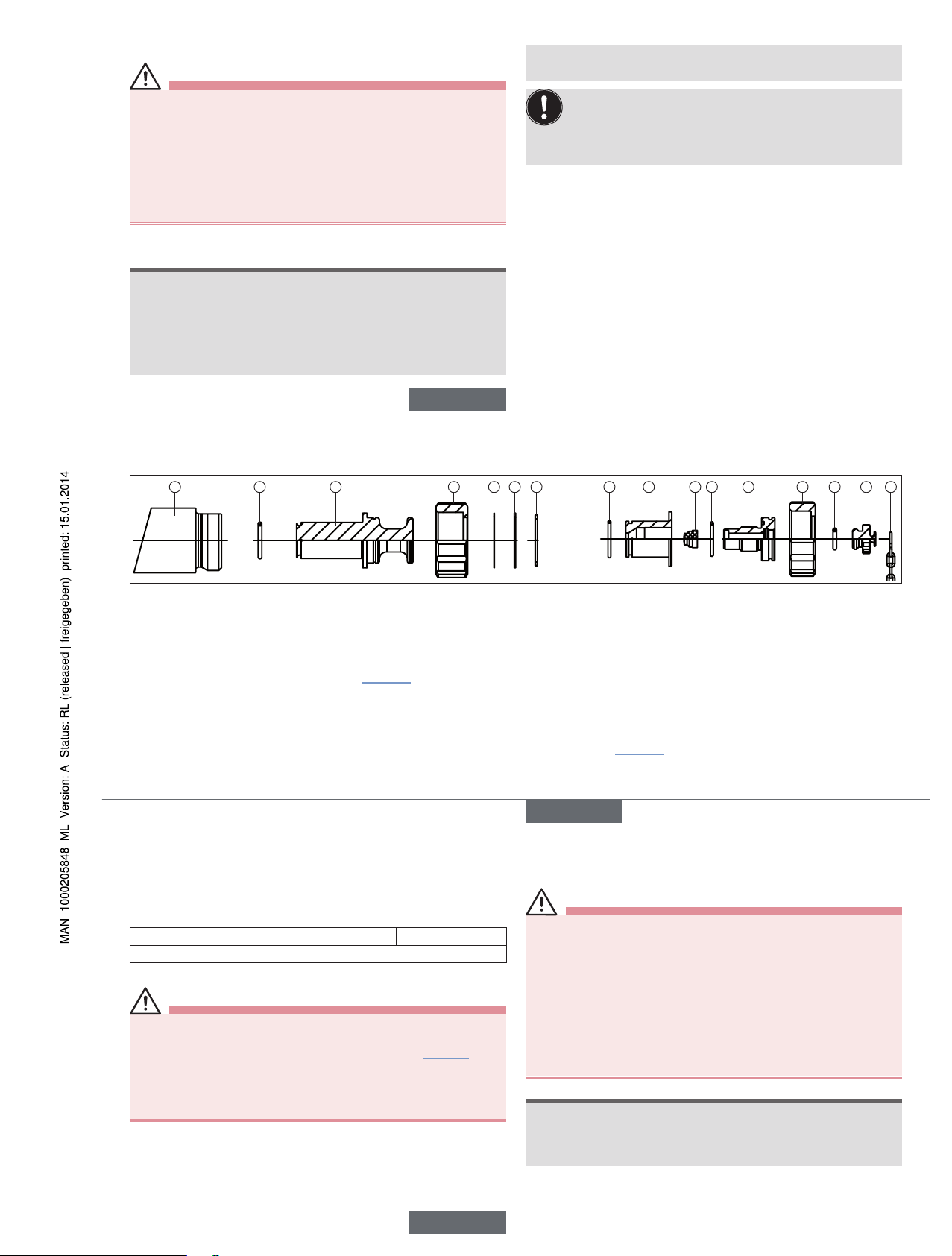
6.2. Montage Blindstopfen und Asepto Probeentnahmestutzen
1 2 3 4 5 6 7 2 8 9
10 11 12 13 14
4
Blindstopfen Asepto Probeentnahmestutzen
Bild 2: Montage Blindstopfen und Asepto Probeentnahmestutzen Typ BBS-11
→ Die Membran (9) vorne bis zum Anschlag in den Probeentnahme-
stutzen (11) schieben und diesen fest mit dem Probeentnahmeingold (8) verschrauben. Achtung: diese Verschraubung darf im
Betrieb oder unter Druck nicht gelöst werden.
→ Diese Baugruppe in den eingeschweißten Stutzen (1) schieben und
mit der Überwurfmutter (4) gut verschrauben. Anziehdrehmoment
beachten (siehe „Tab. 2“). Achtung: diese Verschraubung darf im
Betrieb oder unter Druck nicht gelöst werden.
→ Verschluss (13) auf den Probeentnahmestutzen aufschrauben.
Dies ist die einzige Verschraubung, die während des Betriebs (zum
Zwecke der Probeentnahme) geöffnet werden darf. Die Kette (14)
verhindert, dass der Verschluss verloren geht.
Blindstopfen
→ Die korrekte Lage des O-Rings (2) am Blindingold (3) sicherstellen.
Blindingold in eingeschweißten Ingoldstutzen (1) mit Hilfe der Überwurfmutter (4) einschrauben, um diesen zu verschließen. Anziehdrehmoment beachten (siehe „Tab. 2“).
Eine Probeentnahme ist nun nicht mehr möglich.
Passscheibe (5), Distanzscheibe (6) und Sicherungsring (7) sind im
Lieferzustand bereits montiert und sollten nicht entfernt werden.
Asepto Probeentnahmestutzen
→ Vor dem Einschrauben in den Ingoldstutzen das Vorhandensein und
die korrekte Lage der O-Ringe (2, 10, 12) sicherstellen.
deutsch
15
Nennweite (DN) 25 40
Anziehdrehmoment (Nm)
handfest
Tab. 2: Anziehdrehmoment Überwurfmutter Typ BBS-11 Ingoldstutzen
WARNUNG!
Gefahr durch hohen Druck und Mediumsaustritt!
• Während des Betriebs und/oder anstehendem Druck darf ausschließlich die Kappe zur Probeentnahme (siehe „Bild 2“, Skizze
ganz rechts mit Kette) geöffnet werden. Diese lässt sich mit wenigen
Umdrehungen öffnen.
• Alle anderen Verschraubungen dürfen in diesem Zustand nicht
gelöst werden.
6.3. Demontage
Die Demontage erfolgt in umgekehrter Reihenfolge wie die Montage.
7. INBETRIEBNAHME
WARNUNG!
Verletzungsgefahr bei unsachgemäßem Betrieb!
Nicht sachgemäßer Betrieb kann zu Verletzungen sowie Schäden am
Produkt und seiner Umgebung führen.
• Vor der Inbetriebnahme muss gewährleistet sein, dass der Inhalt
der Bedienungsanleitung dem Bedienungspersonal bekannt ist und
vollständig verstanden wurde.
• Die Sicherheitshinweise und der bestimmungsgemäße Gebrauch
müssen beachtet werden.
• Nur ausreichend geschultes Personal darf die Anlage/das Produkt
in Betrieb nehmen.
• Nach der Montage einen kontrollierten Wiederanlauf gewährleisten.
• Anlage so in Betrieb nehmen, dass sich keine unzulässigen Spannungserhöhungen und Druckschläge ergeben können.
HINWEIS!
Verschleißteile rechtzeitig tauschen
• Die Haltbarkeit der Verschleißteile liegt in der Verantwortung des
Anlagebetreibers. Auf rechtzeitigen Austausch der Verschleißteile
muss geachtet werden.
deutsch
Typ BBS-11
Page 8
16
HINWEIS!
Beschä
digung der Dichtelemente beim Reinigen der Anlage
.
• Zur Reinigung der Anlage möglichst Reinigungsmittel verwenden,
welche die Dichtelemente nicht beschädigen.
• Zur Reinigung keine Drahtbürsten oder Maschinen benützen, die
einen Oberflächenabtrag zur Folge haben.
• Bei Verwendung mechanischer Rohrleitungs-Kontrollgeräte beachten, dass diese keine Beschädigung der Dichtelemente (auch der
Dichtkontur) verursachen.
Beschädigte Dichtelemente müssen ausgetauscht werden!
8. WARTUNG
WARNUNG!
Gefahr durch hohen Druck und Mediumsaustritt!
• Vor dem Lösen von Muttern oder Schrauben unbedingt den Druck
abschalten und Leitungen/Behälter entleeren.
• Bei gefährlichen Medien Schutzausrüstung tragen.
• An unter Druck stehenden Leitungen/Behältern dürfen Muttern oder
Schrauben nur von Fachpersonal unter Beachtung besonderer
Vorsichtsmaßnahmen nachgezogen werden.
• Anlage so abfahren, dass sich keine unzulässigen Spannungserhöhungen und Druckschläge ergeben können.
• Nach der Wartung einen kontrollierten Wiederanlauf gewährleisten.
Produkt regelmäßig durch fachkundiges Personal warten!
Zu den Inspektions- und Wartungsarbeiten gehören insbesondere die
Überwachung und Sicherstellung der
• Dichtheit,
• Kennzeichnung,
• ordnungsgemäßen Funktionsweise der Sicherheits- und
Warneinrichtungen.
deutsch
17
9. ERSATZTEILE
VORSICHT!
Verletzungsgefahr, Sachschäden durch falsche Teile!
Falsches Zubehör und ungeeignete Ersatzteile können Verletzungen
und Schäden am Produkt und dessen Umgebung verursachen.
• Nur Originalzubehör sowie Original-Ersatzteile der Firma Bürkert
verwenden.
Ersatzteile sind: O-Ringe, Silikon-Membran.
Die Ersatzeile können Sie über Ihre Bürkert-Vertriebsniederlassung
bestellen. Die Bestell-Nummern zu den Ersatzteil-Sets entnehmen Sie
bitte dem entsprechenden Datenblatt im Internet.
HINWEIS!
Verschleißteile rechtzeitig tauschen
• Die Haltbarkeit der Verschleißteile liegt in der Verantwortung des
Anlagebetreibers. Auf rechtzeitigen Austausch der Verschleißteile
muss geachtet werden.
10. TRANSPORT, LAGERUNG,
ENTSORGUNG
HINWEIS!
Transportschäden!
Unzureichend geschützte Dichtelemente können durch den Transport
beschädigt werden.
• Produkt in fest zusammengesetztem Zustand vor Nässe und
Schmutz geschützt in einer stoßfesten Verpackung transportieren.
Falsche Lagerung kann Schäden am Produkt verursachen.
• Eine Über- bzw. Unterschreitung der zulässigen Lagertemperatur
vermeiden.
• Produkt trocken und staubfrei lagern!
• O-Ringe und Membran trocken und vor UV-Strahlung geschützt und
nicht länger als 3 Jahre lagern.
• Lagertemperatur –40 … +80 °C.
Umweltschäden durch von Medien kontaminierte Produkte.
• Produkt und Verpackung umweltgerecht entsorgen!
• Geltende Entsorgungsvorschriften und Umweltbestimmungen
einhalten.
deutsch
Typ BBS-11
Page 9

Type BBS-11
Safety ingold socket with Asepto sampling system
Sicherheits-Ingoldstutzen mit Asepto Probeentnahme
Raccord Ingold de sécurité avec prélèvement d'échantillons Asepto
Bedienungsanleitung
Manuel d‘utilisation
Operating Instructions
www.burkert.com
International address
www.burkert.com → Bürkert → Company → Locations
Manuals and data sheets on the Internet : www.burkert.com
Bedienungsanleitungen und Datenblätter im Internet: www.buerkert.de
Instructions de service et fiches techniques sur Internet: www.buerkert.fr
© 2013 Bürkert Werke GmbH
Operating Instr uctions 1401/01_EU-ML_00810326 / Original DE
Bürkert Fluid Control Systems
Sales Center
Christian-Bürkert-Str. 13-17
D-74653 Ingelfingen
Tel. + 49 (0) 7940 - 10 91 111
Fax + 49 (0) 7940 - 10 91 448
E-mail: info@de.buerkert.com
Page 10

18
1. MANUEL D'UTILISATION
Le manuel d'utilisation contient des informations importantes.
• Lire attentivement le manuel d'utilisation et tenir particulièrement
compte des consignes de sécurité.
• Conserver le manuel d'utilisation afin qu'il soit accessible à tous les
utilisateurs.
• La responsabilité et la garantie légale concernant le produit sont
exclues en cas de non-respect du manuel d'utilisation.
1.1. Symboles
→ identifie une opération que vous devez effectuer.
Mise en garde contre les blessures :
DANGER !
Danger imminent ! Blessures graves ou mortelles.
AVERTISSEMENT !
Danger potentiel ! Blessures graves ou mortelles.
ATTENTION !
Danger ! Blessures légères ou de moyenne gravité.
Mise en garde contre les dommages matériels :
REMARQUE !
2. UTILISATION CONFORME
L'utilisation non conforme du type BBS-11 peut présenter
des dangers pour les personnes, les installations proches et
l'environnement.
• Le Type BBS-11 est conçu comme raccord Ingold de sécurité
pour le prélèvement d'échantillons sur des installations en milieu
stérile.
• Lors de son utilisation, il convient de respecter les données et
conditions d'utilisation et d'exploitation admissibles spécifiées
dans le manuel d'utilisation et dans les documents contractuels.
• Les conditions pour l'utilisation sûre et parfaite sont un transport,
un stockage et une installation dans les règles ainsi qu'une utilisation et une maintenance parfaites.
• Veillez à ce que l'utilisation du produit soit toujours conforme.
2.1. Limitations
Lors de l'exportation des produits, veuillez respecter les limitations éventuelles existantes.
2.2. Définition des termes
Le terme « produit » utilisé dans ce manuel désigne toujours le Type
BBS-11.
français
19
4. INDICATIONS GÉNÉRALES
4.1. Adresse
Allemagne
Bürkert Fluid Control Systems
Sales Center
Christian-Bürkert-Str. 13-17
D-74653 Ingelfingen
Tél. + 49 (0) 7940 - 10 91 111
Fax + 49 (0) 7940 - 10 91 448
E-mail: info@de.buerkert.com
International
Les adresses figurent aux dernières pages de la version imprimée du
manuel d'utilisation. Également sur Internet sous : www.burkert.com
4.2. Garantie légale
La condition pour bénéficier de la garantie légale est l'utilisation
conforme du produit dans le respect des conditions d'utilisation
spécifiées.
4.3. Informations sur Internet
Vous trouverez les manuels et les fiches techniques concernant le
Type BBS-11 sur Internet sous : www.buerkert.fr
3. CONSIGNES DE SÉCURITÉ
FONDAMENTALES
Ces consignes de sécurité ne tiennent pas compte des hasards et des
événements pouvant survenir lors du montage, de l'exploitation et de la
maintenance du produit.
Danger dû à la pression élevée et à la sortie de fluide !
• Avant de desserrer les écrous ou les vis, couper impérativement la
pression et vider les conduites/réservoirs.
• En cas d'utilisation de fluides toxiques, porter l'équipement de
protection.
Situations dangereuses d'ordre général
• N'apportez pas de modifications internes ou externes au produit.
• L'actionnement par inadvertance de l'installation ne doit pas être
possible.
• Les travaux d'installation et de maintenance doivent être effectués
uniquement par des techniciens qualifiés et habilités disposant de
l'outillage approprié.
• Le produit doit être utilisé uniquement en parfait état et en respectant le manuel d'utilisation.
• Respecter les dispositions nationales en vigueur dans le pays d'installation lors de l'inspection, de la maintenance et de la réparation.
• Les règles générales de la technique sont d'application pour
planifier l'utilisation et utiliser le produit.
français
20
5. CARACTÉRISTIQUES TECHNIQUES
5.1. Conformité
Le type BBS-11 est conforme aux directives CE conformément à la
déclaration de conformité CE.
5.2. Normes (si applicables)
Les normes utilisées attestant de la conformité avec les directives CE
figurent dans le certificat d'essai de modèle type CE et/ou la déclaration de conformité CE.
5.3. Identification
Les informations concernant le matériau, la dimension du raccord et
le raccordement sont gravées sur le produit. Vous trouverez le numéro
d'identification du produit dans le certificat 3.1 fourni.
Matériau
Numéro de lot du matériau
Dimension d'introduction
Fig. 1 : Exemple d'identification du produit
5.4. Matériaux d'étanchéité
Matériau du joint Température de service
EPDM
-40 à 90 °C, brièvement jusqu'à 140 °C
FEP -60 à 160 °C, brièvement jusqu'à 205 °C
Tab. 1 : Matériaux d'étanchéité BBS-11
5.5. Caractéristiques techniques générales
Matériau
en contact
avec le fluide
Acier inoxydable 1.4435
BN2 (316L)
non en contact
avec le fluide
Acier inoxydable 1.4401 ou
similaire
Membrane silicone
Joint torique EPDM/FEP
Dimensions du tube
Voir identification sur le produit (« Fig. 1 »)
Température d'utilisation admissible
selon le matériau d'étanchéité, voir « Tab. 1 »
Température ambiante -20 °C à +80 °C
Fluides Fluides
Pression de service -1 à +16 bars (en fonction de la température
et de la taille, voir fiche de données)
français
Type BBS-11
Page 11
21
6. MONTAGE
AVERTISSEMENT !
Danger dû à la pression élevée et à la sortie de fluide !
• En cas de travaux sur le produit ou l'installation, couper impérativement la pression et vider les conduites/réservoirs .
• En cas d'utilisation de fluides toxiques, porter l'équipement de
protection.
Risque de blessures dû à un montage non conforme !
• Le montage doit être effectué uniquement par un personnel qualifié
et habilité disposant de l'outillage approprié !
• Empêcher tout actionnement involontaire de l'installation.
6.1. Soudage du raccord Ingold de sécurité
REMARQUE !
Fuites dues à des éléments d'étanchéité endommagés !
• Ne pas souder le produit lorsqu'il est assemblé. Avant le soudage,
retirer impérativement le bouchon et le protéger de la poussière,
des étincelles et d'autres influences !
Fuites dues à un contour d’étanchéité endommagé !
• Pour garantir la fonction d’étanchéité, protéger le contour
d’étanchéité pendant le montage, le soudage et le nettoyage.
• Le contour d'étanchéité ne doit pas être endommagé lors du réusinage du raccord Ingold soudé.
• Après soudure le diamètre Intérieur Di du raccord Ingold
doit être repris pour obtenir les tolérances 25H7 ou 40H7.
• Le soudage et le réusinage du raccord Ingold de sécurité
doivent être effectués uniquement par un personnel suffisamment formé !
→ Pointer le raccord sur toute sa surface sous gaz protecteur.
Lors du nettoyage de la soudure par meulage ou décapage, veiller
avant l'assemblage du raccord à :
• Retirer soigneusement tous les résidus de poussière de meulage et
de décapage.
• Ne pas endommager les inscriptions.
• Ne pas procéder à l'enlèvement de matière au niveau des bords
d'étanchéité. L'enlèvement de matière génère des contours d'étanchéité à arêtes vives endommageant le joint.
• Contrôler la présence de dommages sur le contour d'étanchéité.
Nous recommandons d'établir un rapport de soudage.
français
22
6.2. Montage du faux embout et du raccord pour prélèvement d'échantillons Asepto
1 2 3 4 5 6 7 2 8 9
10 11 12 13 14
4
Faux embout Raccord pour le prélèvement d'échantillons Asepto
Fig. 2 : Montage du faux embout et du raccord pour prélèvement d'échantillons Asepto Type BBS-11
→ Introduire la membrane (9) vers l'avant dans le raccord pour pré-
lèvement d'échantillons (11) jusqu'en butée et serrer à fond ce
dernier avec le raccord Ingold pour le prélèvement d'échantillons
(8). Attention : cette pièce vissée ne doit pas être desserrée
pendant le fonctionnement ou lorsque l'assemblage est sous
pression.
→ Insérer maintenant ce groupe de pièces dans le raccord soudé (1)
et bien le serrer avec l'écrou-raccord (4). Respecter le couple de
serrage (voir « Tab. 2 »). Attention : cette pièce vissée ne doit pas
être desserrée pendant le fonctionnement ou lorsque l'assemblage
est sous pression.
Faux embout
→ S'assurer que le joint torique (2) est correctement placé sur le faux
embout Ingold (3). Visser le faux embout Ingold dans le raccord
Ingold soudé (1) à l'aide de l'écrou-raccord (4) pour fermer celuici. Respecter le couple de serrage (voir « Tab. 2 »).
Il n'est désormais plus possible de prélever des échantillons. À l'état
de livraison, la rondelle d'ajustage (5), la rondelle d'écartement (6) et la
bague de sécurité (7) sont déjà montées et ne doivent pas être retirées.
Raccord pour le prélèvement d'échantillons Asepto
→ Avant insertion dans le raccord Ingold, vérifier la présence et la
position correcte des joints toriques (2, 10, 12).
français
23
→ Visser la fermeture (13) sur le raccord pour prélèvement d'échan-
tillons. C'est la seule pièce vissée qui a le droit d'être ouverte
pendant le fonctionnement (pour prélever les échantillons). La
chaîne (14) empêche que la fermeture ne s'égare.
Diamètre nominal (DN) 25 40
Couple de serrage (Nm)
serré à la main
Tab. 2 : Couples de serrage de l'écrou-raccord type BBS-11 raccord Ingold.
AVERTISSEMENT !
Danger dû à la pression élevée et à la sortie de fluide !
• Pendant le fonctionnement et/ou en présence de pression, seul
le capuchon pour le prélèvement d'échantillons (voir « Fig. 2 »,
croquis de droite avec la chaîne) peut être ouvert. Celui-ci s'ouvre
en quelques tours.
• Toutes les autres pièces vissées ne doivent pas être desserrées
dans cet état.
6.3. Démontage
Le démontage a lieu dans le sens inverse du montage.
7. MISE EN SERVICE
AVERTISSEMENT !
Risque de blessures en cas d'utilisation non conforme !
Une utilisation non conforme peut entraîner des blessures et
endommager le produit et son environnement.
• Avant la mise en service, il faut s'assurer que le contenu du manuel
est connu et parfaitement compris par les opérateurs.
• Respecter les consignes de sécurité et l'utilisation conforme.
• L'installation/le produit doit être mis(e) en service uniquement par
un personnel suffisamment formé.
• Garantir un redémarrage contrôlé après le montage.
• Mettre l'installation en service en veillant à empêcher les
augmentations de tension et les coups de bélier inadmissibles.
REMARQUE !
Remplacer les pièces d'usure dans les délais raisonnables
• La durée des pièces d'usure relève de la responsabilité de
l'exploitant de l'installation. Veiller au remplacement des pièces
d'usure dans les délais raisonnables.
français
Type BBS-11
Page 12

24
REMARQUE !
Endom
magement des éléments d'étanchéité lors du nettoyage
de l'installation
.
• Pour nettoyer l'installation, utiliser dans la mesure du possible
des produits de nettoyage n'endommageant pas les éléments
d'étanchéité.
• Pour le nettoyage, ne pas utiliser de brosses métalliques ou de
machines attaquant la surface.
• Si vous utilisez des appareils de contrôle mécaniques pour tuyauteries, veiller à ce que ceux-ci n'endommagent pas les éléments
d'étanchéité (ni le contour d'étanchéité).
Les éléments d'étanchéité endommagés doivent être
remplacés !
8. MAINTENANCE
AVERTISSEMENT !
Danger dû à la pression élevée et à la sortie de fluide !
• Avant de desserrer les écrous ou les vis, couper impérativement la
pression et vider les conduites/réservoirs.
• En cas d'utilisation de fluides toxiques, porter l'équipement de
protection.
• Seuls les techniciens qualifiés sont autorisés à resserrer écrous
et vis sur les tuyauteries/cuves sous pression en respectant les
mesures de sécurité spécifiques.
• Mettre l'installation hors service en veillant à empêcher les augmentations de tension et les coups de bélier inadmissibles.
• Garantir un redémarrage contrôlé après la maintenance.
Faire effectuer régulièrement l'entretien du produit par un
personnel spécialisé !
Font notamment partie des travaux d'inspection et de maintenance, la
surveillance et la garantie de
• l'étanchéité,
• l'identification,
• et le parfait fonctionnement des dispositifs de sécurité et
d'avertissement.
français
25
9. PIÈCES DE RECHANGE
ATTENTION !
Risque de blessures, de dommages matériels dus à de mauvaises pièces !
De mauvais accessoires ou des pièces de rechange inadaptées
peuvent provoquer des blessures et endommager le produit ou son
environnement.
• Utiliser uniquement des accessoires et des pièces de rechange
d'origine de la société Bürkert.
Les pièce de rechange sont les joints toriques, la membrane en
silicone.
Vous pouvez commander les pièces de rechange auprès de votre filiale de
distribution Bürkert. Les numéros d'article des jeux de pièces de rechange
sont indiqués sur la fiche de données correspondante sur Internet.
REMARQUE !
Remplacer les pièces d'usure dans les délais raisonnables
• La durée des pièces d'usure relève de la responsabilité de l'exploitant de l'installation. Veiller au remplacement des pièces d'usure
dans les délais raisonnables.
10. TRANSPORT, STOCKAGE,
ÉLIMINATION
REMARQUE !
Dommages dus au transport !
Les éléments d'étanchéité insuffisamment protégés peuvent être
endommagés pendant le transport.
• Transporter le produit, bien assemblé, à l'abri de l'humidité et des
impuretés et dans un emballage résistant aux chocs.
Un mauvais stockage peut entraîner des dommages sur le
produit.
• Éviter le dépassement vers le haut ou le bas de la température de
stockage admissible.
• Stocker le produit au sec et à l'abri des poussières !
• Stocker les joints toriques et la membrane au sec et à l'abri des UV,
la durée de stockage ne devant pas dépasser 3 ans.
• Température de stockage -40 à +80 °C.
Dommages sur l'environnement causés par des produits contaminés par des fluides.
• Éliminer le produit et l'emballage dans le respect de l'environnement !
• Respecter les prescriptions en matière d'élimination des déchets et
de protection de l'environnement en vigueur.
français
Type BBS-11
 Loading...