

Burnham 8B Series, 805B, 806B, 810B, 807B Installation, Operating And Servicing Instructions
...Page 1
SEIRESB8
RELIOBDERIF-SAG
DNAGNITAREPO,NOITALLATSNI
ROFSNOITCURTSNIECIVRES
,reliobnonoitamrofnignikeesnehW.rotcartnocgnitaehruoyllac,reliobotsriaperroecivresroF
.lebaLgnitaRnonwohssarebmuNlaireSdnarebmuNledoMrelioBedivorp
rebmuNledoMrelioBrebmuNlaireSrelioBetaDnoitallatsnI
____-_____8________6
rotcartnoCgnitaeH rebmuNenohP
sserddA
8141602R13-7/03
1
Price - $5.00
Page 2
IMPORTANT INFORMATION - PLEASE READ THIS PAGE CAREFULLY
NOTE: The equipment shall be installed in accordance with those installation regulations enforced in the area where the
installation is to be made. These regulations shall be carefully followed in all cases. Authorities having jurisdiction
shall be consulted before installations are made.
All wiring on boilers installed in the USA shall be made in accordance with the National Electrical Code and/or local
regulations.
All wiring on boilers installed in Canada shall be made in accordance with the Canadian Electrical Code and/or local
regulations.
This Series 8B Boiler has been approved by the Massachusetts Board of Plumbers and Gas Fitters:
Approval No. G1-0202-11A.
The Commonwealth of Massachusetts requires this product to be installed by a licensed Plumber or Gas Fitter.
The following terms are used throughout this manual to bring attention to the presence of hazards of various risk levels,
or to important information concerning product life.
REGNAD
noitautissuodrazahyltnenimminasetacidnI
,htaednitluserlliw,dediovatonfi,hcihw
ytreporplaitnatsbusroyrujnisuoires
.egamad
.egamad
GNINRAW
noitautissuodrazahyllaitnetopasetacidnI
,htaednitluserdluoc,dediovatonfi,hcihw
ytreporplaitnatsbusroyrujnisuoires
.egamad
NOITUAC
noitautissuodrazahyllaitnetopasetacidnI
nitluseryam,dediovatonfi,hcihw
ytreporproyrujnironimroetaredom
ECITON
nosnoitcurtsnilaicepssetacidnI
ecnanetniamro,noitarepo,noitallatsni
otdetalertontubtnatropmierahcihw
.sdrazahyrujnilanosrep
REGNAD
rosihtfoytinicivehtnisdiuqilrosropavelbammalfrehtoroenilosagesuroerotsTONOD
.ecnailpparehtoyna
lacirtceleynahcuotTONOD-ecnailppaynaetarepootyrtTONOD,sropavsagllemsuoyfI
yletomeramorfreilppussagehtllac,yletaidemmI.gnidliubehtnienohpynaesurohctiws
,elbaliavanusireilppusehtfirosnoitcurtsnis'reilppussagehtwolloF.enohpdetacol
.tnemtrapederifehttcatnoc
elbitsubmocrevoetercnoc,teprac,gniroolfelbitsubmocnoreliobsihtllatsniTONOD
rognipipcitsalpsahcuslairetamdetceffataehynarevoetercnocnoron,doowrogniroolf
.dleihsroolfelbitsubmocdellatsniylreporpatuohtiwgniriw
2
Page 3
GNINRAW
ehtwolloF.ylefasetarepootecivresdnaecnanetniamralugerseriuqerreliobsihT
.launamsihtnideniatnocsnoitcurtsni
ytreporpesuacnacecnanetniamroecivres,noitaretla,tnemtsujda,noitallatsnireporpmI
erofeblaunameritneehtdnatsrednudnadaeR.efilfossolroyrujnilanosrep,egamad
ebtsumecivresdnanoitallatsnI.ecivresro,noitarepopu-trats,noitallatsnignitpmetta
.ycnegaecivresrorellatsnidelliksdna,decneirepxe,elbaegdelwonkaybylnodemrofrep
.detnevylreporpebtsumreliobsihT
snoisivorperaerehtosdellatsniebtsumdnanoitarepoefasrofriahserfsdeenreliobsihT
.rianoitalitnevdnanoitsubmocetauqedarof
ehtfotratsehterofebdenaelcdnadetcepsniebtsummetsysgnitnevehtforoiretniehT
rofnosaesgnitaehehttuohguorhtyllacidoirepdetcepsniebdluohsdnanosaesgnitaeh
suoixonwollaotyrassecensimetsystnevdetcurtsbonudnanaelcA.snoitcurtsboyna
drawotetubirtnoclliwdnaylefastnevotefilfossolroyrujniesuacdluoctahtsemuf
.ycneiciffes'reliobehtgniniatniam
gnippatehtotnidellatsnisievlavfeilererusserpasselnuetelpmoctonsinoitallatsnI
roflaunamsihtfonoitceSmirTdnagnipiPretaWehteeS-reliobfopotehtnodetacol
.sliated
dnanwodtuhsotreliobehtesuacyamhcihwsecivedytefashtiwdeilppussireliobsihT
gnitaeheht,ytilibissopasisepipnezorfoteudegamadfI.ecivrestuohtiwtrats-erton
dnasdraugefasetairporpparo;rehtaewdlocnidednettanutfelebtondluohsmetsys
sireliobehtfiegamadtneverpotmetsysgnitaehehtnodellatsniebdluohssmrala
.evitareponi
sgnittifepipynawercsnutonoD.erusserphgihrednuretawtohyrevsniatnocreliobsihT
ehtgnirussaylevitisoptuohtiwreliobsihtfostnenopmocynatcennocsidottpmettaron
nehwtnempiuqednagnihtolcevitcetorpraewsyawlA.erusserponsahdnaloocsiretaw
ehtnoylertonoD.seirujnidlacstneverpotreliobsihtgnicivresropugnitrats,gnillatsni
.reliobehtfoerusserpdnaerutarepmetehtenimretedotseguagerutarepmetdnaerusserp
oD.gnitareposireliobehtnehwtohyrevemocebhcihwstnenopmocsniatnocreliobsihT
.loocerayehtsselnustnenopmocynahcuotton
,animulaniatnocleufehtdnanoitsubmocfostcudorp,noitcurtsnocfoslairetamrelioB
rocixotrehtoro/dnasedyhedla,sedixonegortin,edixonomnobrac,slatemyvaeh,acilis
ehtotnwonkerahcihwdnayrujnisuoiresrohtaedesuacnachcihwsecnatsbuslufmrah
esusyawlA.mrahevitcudorperrehtodnastcefedhtrib,recnacesuacotainrofilaCfoetats
ehtybraengnikrowrognicivresnehwtnempiuqednasrotaripser,gnihtolcytefasreporp
.ecnailppa
.htaedroyrujnilanosrepesuacnacredroreporpehtnisnoitcurtsnillawollofoteruliaF
slaunamsrerutcafunamtnenopmocnideniatnocesohtllagnidulcni,snoitcurtsnilladaeR
rogniniatniam,gnitarepo,pugnitrats,gnillatsnierofebreliobehthtiwdedivorperahcihw
.gnicivres
elbammalfrehtodnaenilosag,slairetamelbitsubmocmorfeerfdnaraelcaerareliobpeeK
.sdiuqilrosropav
.retawottcejbusneebsahhcihwlortnochtiwreliobetarepotonoD
.semitllataecalpniebtsumsdraugdnaserusolcne,setalprevocllA
ECITON
.launamsihtfokcabehtnodetnirpsihcihwfoypoca,ytnarrawdetimilasahreliobsihT
yltcerroceraslortnocllatahteesotrotcartnocgnillatsniehtfoytilibisnopserehtsitI
.etelpmocsinoitallatsniehtnehwylreporpgnitarepoeradnadellatsni
evahlevelaesevobateef000,2nahtretaergsedutitlatanoitallatsniroftliubsreliobASU
replevelaesevobateef000,1reptnecrep4etartupnisagecuderotdecifiroyllaicepsneeb
naidanaC.FxidneppAdna2.1.8noitceS,1.322ZISNA/45APFN,edoCsaGleuFlanoitaNeht
.lebalgnitarehtnodetacidnisignizisecifiro'sreliob
3
Page 4

Table of Contents
I. Pre-Installation ................................................ 6
II. Boiler Assembly ................................................ 8
III. Gas Control System Assembly ....................... 15
(Knockdown Boilers)
IV. Water Trim and Piping .................................... 27
V. Gas Piping ....................................................... 31
VI. Venting ............................................................33
VII. Electrical .......................................................... 36
VIII. System Start-up ............................................... 59
IX. Service ............................................................. 68
X. Repair Parts ..................................................... 75
4
Page 5
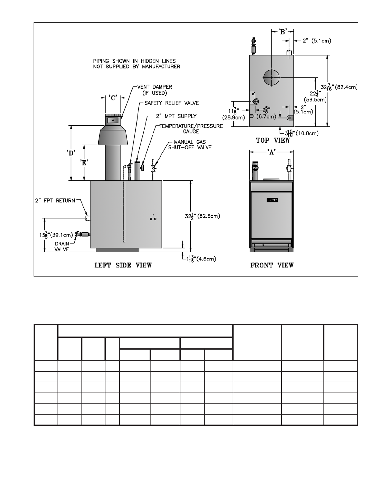
Table 1: Dimensional Data
Figure 1: Dimensional Data
relioB
ledoM
ABC
.oN
B50802017 61/31-4261/31-428/1-618/1-61.tf51x.aid"79.11096
B6084/3-328/7-118 61/31-724/3-528161.tf51x.aid"89.31077
B7082/1-724/3-319 61/31-824/3-528161.tf51x.aid"99.51578
B8084/1-138/5-519 61/31-0361/11-620261.tf51x.aid"99.71089
B908532/1-71012/1-3361/7-622251.tf51x.aid"019.910801
B0184/3-838/3-91012/1-3361/7-622251.tf51x.aid"019.120021
)1(
.)"4/1-73silenap
)2(
)3(
)4(
)sehcnI(snoisnemiD
DE
ASUadanaCASUadanaC
TPN1:ezisnoitcennocsaG
)ylnOretaW(isp05:erusserPgnikroWelbawollAmumixaM
.rellatsniybdeilppussenilneddihninwohssmetI
5
dednemmoceR
eziSyenmihC
)dnuoR(
retaW
tnetnoC
)snollaG(
.xorppA
gnippihS
thgieW
)BL(
pottekcajotroolf(thgiehreliobot"4/3-4sdda;gniroolfelbitsubmocnosnoitallatsnirofderiuqeresablaicepS
Page 6
I. Pre-Installation
GNINRAW
erofebsnoitcurtsnilladaerylluferaC
llawollofoteruliaF.reliobgnillatsni
esuacnacredroreporpnisnoitcurtsni
.htaedroyrujnilanosrep
A. Inspect shipment carefully for any signs of damage.
All equipment is carefully manufactured, inspected and
packed. Our responsibility ceases upon delivery of
boiler to carrier in good condition. Any claim for
damage or shortage in shipment must be filed
immediately against carrier by consignee. No claims
for variances or shortages will be allowed by Boiler
Manufacturer, unless presented within sixty (60) days
after receipt of equipment.
B. Installation must conform to the requirements of the
authority having jurisdiction. In the absence of such
requirements, installation must conform to the
National Fuel Gas Code, NFPA 54/ANSI Z223.1 and/
or CAN/CGA B149 Installation Codes. Where
required by the authority having jurisdiction, the
installation must conform to the Standard for Controls
and Safety Devices for Automatically Fired Boilers,
ANSI/ASME No. CSD-1.
C. Provide clearance between combustible material
and boiler jacket (following clearances are minimums):
1. USA, 805B-807B: listed for Alcove installation
a. Front: 18"
b. Top: 36"
c. Draft hood, rear, sides and flue connector: 6"
2. USA, 808B-810B: for installation in room which is
large in comparison with size of boiler.
a. Front: 18"
b. Top: 51½"
c. Draft hood, rear, sides, and flue connector: 6"
3. Canada, 805B-810B:
a. Top and front: 18" (45.7cm)
b. Flue, rear and sides: 6" (15.2cm)
D. Provide clearance for servicing and proper operation
(following clearances are recommended and may be
reduced to minimum clearances shown above):
1. Single boiler, 805B-807B, Front/Top: 24" (61cm)
2. Single boiler, 808B-810B, Front/Top: 48" (122cm)
3. Multiple/modular boiler, USA/Canada, Sides:
1" (2.5cm)
E. Install boiler on level floor as close to chimney as
possible. For basement installation provide a solid base
such as concrete or masonry construction if floor is not
level or if water may be encountered on floor around
boiler.
F. Protect gas ignition system components from water
(dripping, spraying, rain, etc.) during boiler operation
and service (circulator replacement, control
replacement, etc.).
GNINRAW
noitallatsnirofdeifitrecngisedsiecnailppA
roF.ylnogniroolfelbitsubmocnonno
ylnogniroolfelbitsubmocnonoitallatsni
elbaTnidetsilesablaicepsnodellatsninehw
.gnitepracnodellatsniebtontsumrelioB.2
sihcihwetercnocnodellatsnisireliobnehW
gnitlemottcejbussitahtlairetamarevo
laicepseht,).cte,gnibuttnaidarXEP,CVP(
tonsidapetercnocA.desuebtsumesab
.gniroolfelbitsubmoctcetorpottneiciffus
Table 2: Special Base Required for Installation on
Combustible Flooring
.oNledoMrelioBrebmuNtraPesaBlaicepS
B50855061816
B60856061816
B70857061816
B80858061816
B90859061816
B01850161816
G. Provide combustion and ventilation air in
accordance with applicable provisions of local building
codes, or the National Fuel Gas Code, NFPA 54/ANSI
Z223.1, Section 5.3, Air for Combustion and
Ventilation; or CAN/CGA B149 Installation Codes,
Part 5, Venting Systems and Air Supply for
Appliances.
GNINRAW
rianoitalitnevdnanoitsubmocetauqedA
reporperussaotdedivorpebtsum
.noitsubmoc
The following guideline is based on the National Fuel
Gas Code, NFPA 54/ANSI Z223.1.
1. Determine volume of space (boiler room). Rooms
communicating directly with space (through
permanent openings not furnished with doors) are
considered part of space.
Volume [ft³] = Length [ft] x Width [ft] x Height [ft]
2. Determine Total Input of all appliances in space.
Round result to nearest 1,000 Btu per hour (Btuh).
3. Determine type of space. Divide Volume by Total
Input.
6
Page 7

a. If result is greater than or equal to 50 ft³ per 1,000
Btuh, space is considered an unconfined space.
b. If result is less than 50 ft³ per 1,000 Btuh, space is
considered a confined space.
4. Determine building type. A building of unusually
tight construction has the following characteristics:
a. Walls and ceiling exposed to outside atmosphere
have a continuous water vapor retarder with a
rating of 1 perm or less with openings gasketed
and sealed, and
b. Weather-stripping has been added on openable
windows and doors, and
c. Caulking or sealants applied in joints around
window and door frames, between sole plates
and floors, between wall-ceiling joints, between
wall panels, at plumbing and electrical
penetrations, and at other openings.
5. For boiler located in an unconfined space in a
building of other than unusually tight construction,
adequate combustion and ventilation air is normally
provided by fresh air infiltration through cracks
around windows and doors.
6. For boiler located in an unconfined space in a
building of unusually tight construction or in a
confined space, provide outdoor air through
permanent opening(s) which communicate directly
or by duct with the outdoors or spaces (crawl or
attic) freely communicating with the outdoors.
Minimum dimension of air opening(s) is 3" (7.6cm).
a. Two permanent openings: Locate one opening
within 12 " (30.5cm) of top of space. Locate
remaining opening within 12" (30.5cm) of bottom
of space. Size each opening per following:
i. Minimum free area of 1 square inch per 3,000
Btu per hour input of all equipment in space.
ii. Free area shall not be less than the sum of
the areas of all vent connectors in the
confined space.
Alternate method for boiler located within confined
space. Use indoor air if two permanent openings
communicate directly with additional space(s) of
sufficient volume such that combined volume of all
spaces meet criteria for unconfined space. Size each
opening for minimum free area of 1 square inch per
1,000 Btu per hour input of all equipment in
spaces, but not less than 100 square inches.
7. Ventilation Duct Louvers and Grilles. Equip
outside openings with louvers to prevent entrance
of rain and snow, and screens to prevent entrance of
insects and rodents. Louvers and grilles must be
fixed in open position or interlocked with
equipment to open automatically before burner
operation. Screens must not be smaller than ¼ inch
mesh.
Consider the blocking effect of louvers, grilles and
screens when calculating the opening size to
provide the required free area. If free area of louver
or grille is not known, assume wood louvers have
20-25 percent free area and metal louvers and
grilles have 60-75 percent free area.
8. For Specially Engineered Installations. The above
requirements shall be permitted to be waived where
special engineering, consistent with good
engineering practice and approved by the authority
having jurisdiction, provides an adequate supply of
air for combustion, ventilation, and dilution of flue
gases.
i. Direct communication with outdoors.
Minimum free area of each opening must be
1 square inch per 4,000 Btu per hour input
of all equipment in space.
ii. Vertical ducts. Minimum free area of each
opening must be 1 square inch per 4,000
Btu per hour input of all equipment in
space. Duct cross-sectional area shall be
same as opening free area.
iii. Horizontal ducts. Minimum free area of
each opening must be 1 square inch per
2,000 Btu per hour input of all equipment
in space. Duct cross-sectional area shall be
same as opening free area.
b. One permanent opening shall be permitted where
the boiler has clearances of at least 1" (2.5cm)
from the sides and rear and 6" (15.2cm) from the
front. Locate the opening within 12 " (30.5cm) of
top of space. Size opening per following:
GNINRAW
rehtoroenilosagerehwreliobllatsnitonoD
fosecruosro,sdiuqilrosropavelbammalf
,srenaelc,sehcaelb.e.i(snobracordyh
cirbaf,srevomertniap,syarps,slacimehc
.derotsrodesuera).cte,srenetfos
ECITON
ehtotdragerhtiwreliobehtfognizis-siM
evissecxenitluserlliwdaolmetsysgnitaeh
tnenopmocdetareleccadnagnilcycreliob
tnarrawTONSEODmahnruB.eruliaf
reliobdezis-simybdesuacseruliaf
otreliobehtezisrevoTONOD.snoitacilppa
yltaergsreliobelpitlum/raludoM.metsyseht
.gnizisrevoreliobfodoohilekilehtecuder
7
Page 8
II. Boiler Assembly
A. Remove Crate (Semi-Pak and Packaged Only)
1. Remove all fasteners at crate skid.
2. Lift outside container and remove with all other
inside protective spacers and bracing.
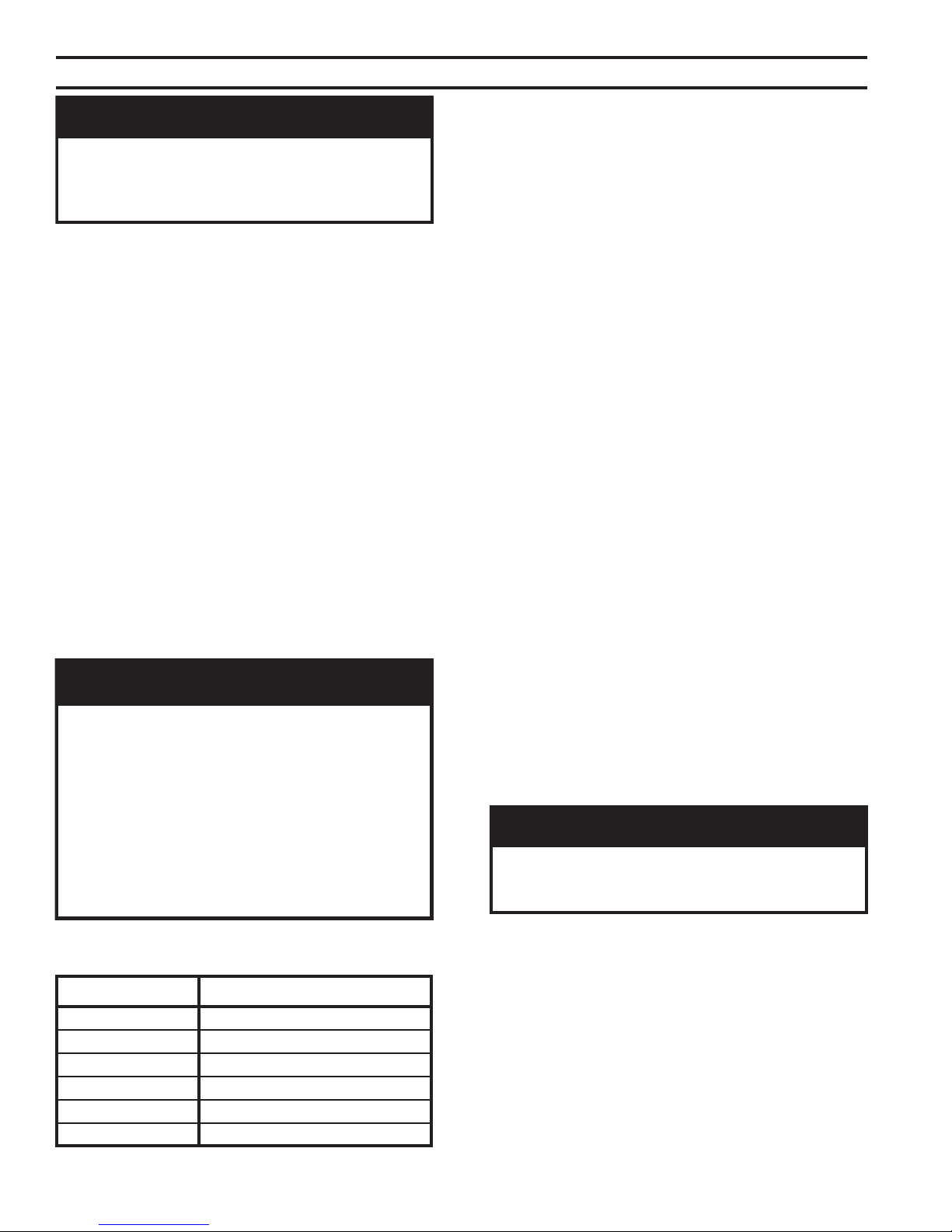
B. Remove boiler from skid. See Figure 2. Exercise care
to avoid dropping boiler.
1. Place boiler in approximate location. Refer to
Section I: Pre-Installation. Remove base hold down
bolts.
2. Using pry bar under rear corner of Base End Panel,
raise boiler and install 1½" wood blocks under rear
corners. Install ¾" pipe roller between Base and
skid.
3. Remove 1½" wood blocks. Place 3" pipe roller on
floor behind skid.
4. Roll boiler off skid. Move skid out of way.
Figure 2: Skid Removal
Table 3: Purpose of Tappings
gnippaTeziSesopruP
A"2ylppuS
B"2nruteR
C"¾evlaVfeileR
D"¾timiL
E"¾timiLyrailixuA
F"¾tuohsaW
G"¾niarD
Figure 3: Tapping Locations
8
Page 9
5. Roll boiler until 3" roller is located as shown. Use
pry bar to install wood blocks under front corners of
base. Remove 3" roller.
6. Lift boiler with pry bar. Remove wood blocks.
Lower boiler.
C. For Packaged Boiler only, proceed to Paragraph E.
D. Test Section Assembly for leaks before connecting to
system and installing controls, trim and jacket. Refer
to Figure 3 and Table 3.
1. Plug Tappings C & E (¾ NPT) and Return Tapping
B (2 NPT).
2. Insert ¾" NPT x ¼" NPT bushing in Tapping D.
Install pressure gauge capable of indicating 50 psi.
3. Insert 2" NPT x ¾" NPT bushing in Supply
Tapping A. Install purge valve with a hose that
runs to a drain.
4. Connect fill valve and piping to Drain Tapping G.
GNINRAW
.reliobtsetkaelotriaesutonoD
5. Fill boiler completely with water by venting air
through purge valve. Close purge valve and apply
water pressure of at least 10 psi but less than 50 psi
gauge pressure.
6. Examine boiler for leaks or damage due to
shipment or handling.
7. Remove plugs from Return Tapping B, Tapping C,
and Tapping E (if second limit or operating control
is used). Also remove fill valve and piping, purge
valve and piping, and pressure gauge.
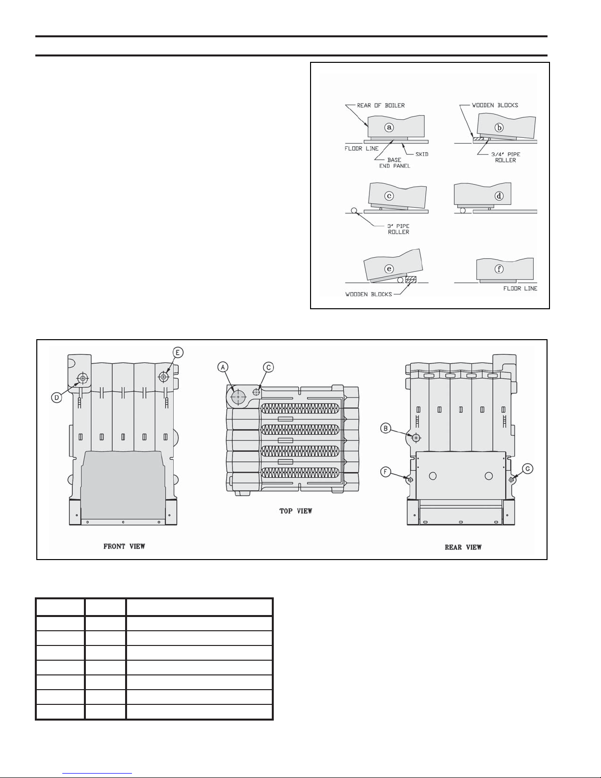
E. Install special base if installation is on combustible
flooring. See Figure 4. Floor shield adds 4¾" to boiler
height.
1. Place special base on combustible floor with surface
marked "FRONT" in upward position.
2. Locate special base with spacing to combustible
materials as shown in Figure 4.
3. Place boiler on special base. Boiler must rest inside
locating brackets. Boiler jacket panels will
overhang special base.
4. Do not enclose boiler (including special base) on all
four sides. Models 805B - 807B may be enclosed
Figure 4: Installation of Special Base for Combustible Flooring
9
Page 10
Figure 5: General Assembly (Knockdown Boilers)
on three sides (alcove) while maintaining
clearances shown in Figure 4.
F. Move boiler to permanent location by sliding or
walking. DO NOT DROP.
For Packaged Boiler proceed to Section IV: Trim and
Piping.
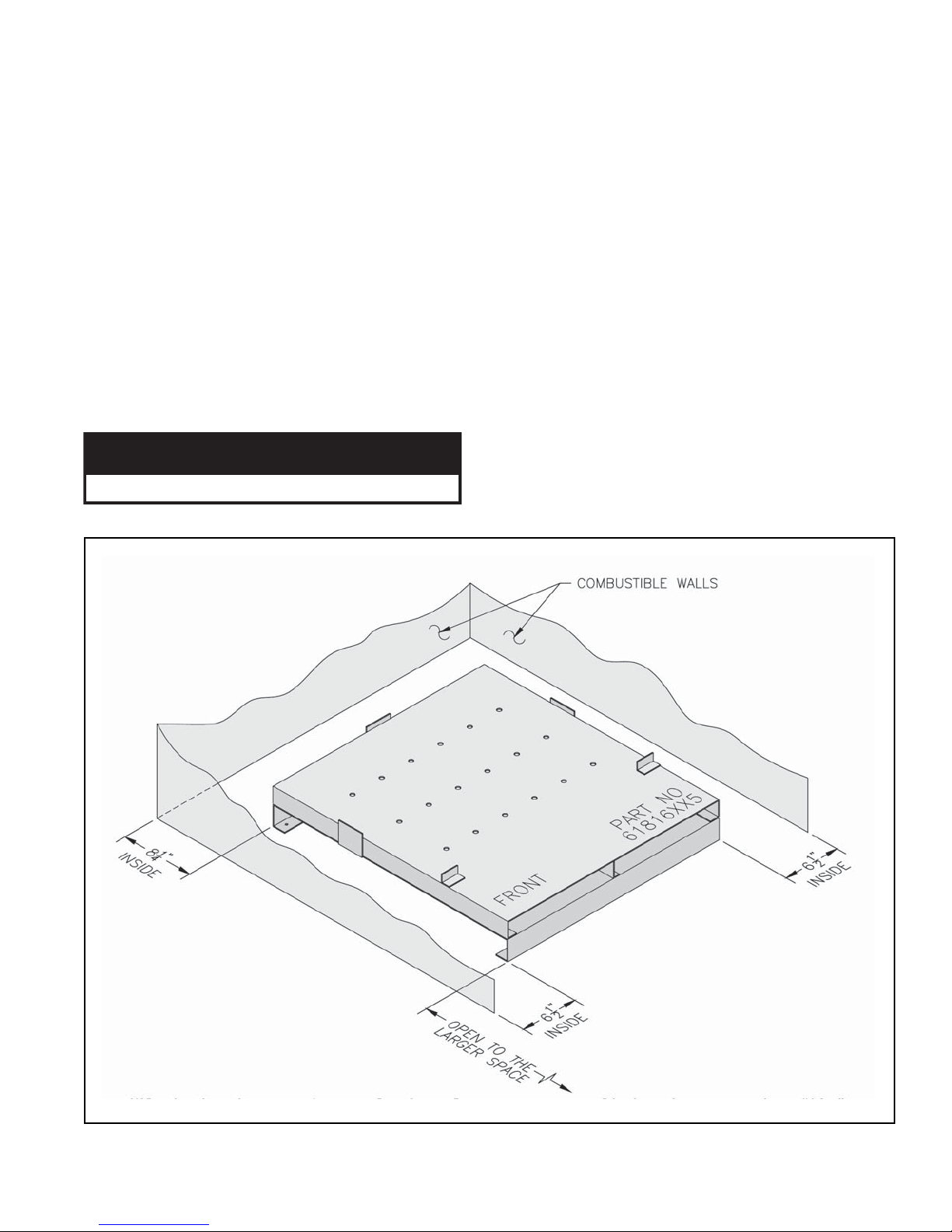
G. Install Canopy on section assembly. See Figure 5.
Canopy and hardware are located in Combination
Boiler Parts and Control Carton.
1. Position Canopy on top of Section Assembly.
Locate between end sections and sealing ledge on
front and back of each section.
2. Fasten each end with ¼" - 20 x 1" carriage bolts,
washers and nuts.
3. Seal between Canopy and Section Assembly with
furnace cement.
H. Inspect joints between sections. They were factory
sealed. If any openings resulted during shipment or
handling, reseal with furnace cement. Confirm tie rods
are only hand tight to allow for thermal expansion.
I. Install Base Front Panel. See Figure 5. Panel and
hardware located in Combination Boiler Parts and
Control Carton.
1. Attach Base Front Panel to Section Assembly using
¼" - 20 x 1¼" carriage bolts, washers and nuts.
2. Seal between top of Base Front Panel and Section
Assembly with furnace cement (shipped in
Combination Boiler Parts and Control Carton).
3. Seal between top of Base Rear Panel and Section
Assembly with furnace cement.
J. Install Pilot/Main Burner Assembly. See Figure 7.
Assembly is located in Combination Boiler Parts and
Control Carton. Verify assembly is properly located on
support bracket in Base Rear Panel, seated on Main
Burner Orifice, and secured with hitch pin clip.
K. Attach Flame Roll-out Switch to Burner Access
Panel. See Figure 6. Flame Roll-out Switch and
hardware are located in Combination Boiler Parts and
Control Carton. Flame Roll-out Switch is a single use
device - do not test with heat - switch cannot be reset.
10
Page 11
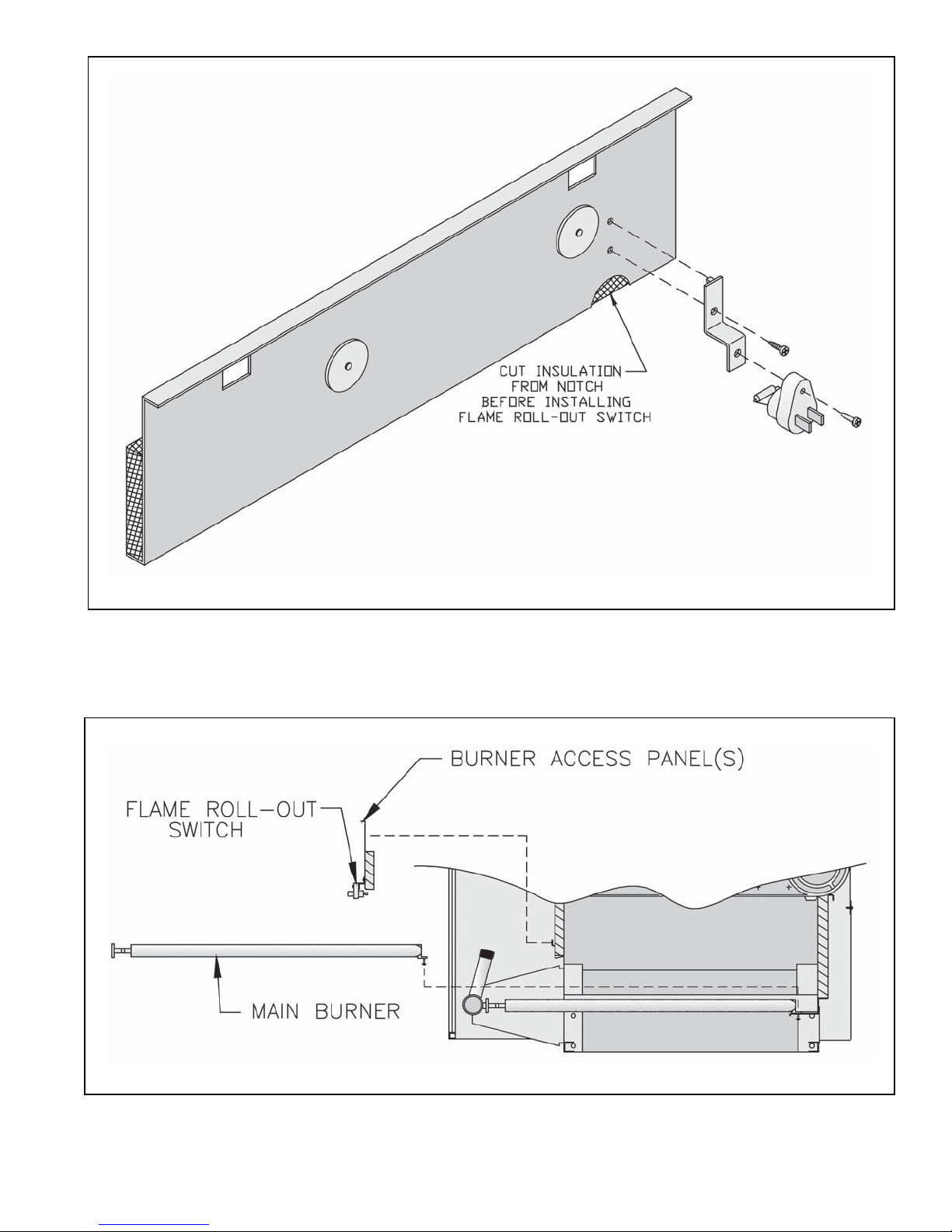
Figure 6: Flame Roll-out Switch Installation
Figure 7: Burner/Burner Access Panel Installation
11
Page 12

1. Cut insulation from semicircular notch at right end of
the burner access panel. Models 808B - 810B have
two (2) burner access panels. Remove insulation
from notch of right side burner access panel only.
2. Attach Flame Roll-out Switch Mounting Bracket to
burner access panel with (1) #8 x ½" lg. sheet metal
screw.
3. Attach Flame Roll-out Switch to mounting bracket
with (1) #8 x ¾" lg. sheet metal screw.
L. Install Burner Access Panel(s). Locate Burner
Access Panel(s) in Combination Boiler Parts and
Control Carton. Engage Burner Access Panel holes
with projections on Base Front Panel. See Figure 6.
M. Install Immersion Well(s).
1. Remove Immersion Well(s) from Combination
Boiler Parts and Control Carton..
2. Insert Immersion Well in Tapping D. See Figure 3.
3. If second limit or operating control is used, insert
immersion well in Tapping E. If vertical gas
piping is to be installed inside of boiler jacket, it is
recommended that second limit be installed in
system piping.
7. Attach Lower Front Tie Bar to Left Side and Right
Side Panels.
8. Engage Upper Front Panel in slots on Left Side and
Right Side Panels. Place Top Panel in position.
Attach Top Panel to Left Side, Right Side and
Upper Rear Panels.
9. Tighten all jacket screws.
10. Affix Lighting/Operating Instructions Label and
Wiring Diagram Label to inside of Front
Removable Door. Labels are located in
Combination Boiler Parts and Control Carton.
O. Install Junction Box. See Figure 8. Attach junction
box to inside of Left Side Panel with ¼" - 20 x ¼" lg.
machine screw (located in Combination Boiler Parts
and Control Carton).
P. Install Limit Control. Locate limit in Combination
Boiler Parts and Control Carton. Insert limit probe into
left immersion well as far as possible. Tighten set
screw.
Q. Install Auxiliary Limit or operating control (if used).
Insert control probe into right immersion well as far as
possible. Tighten set screw.
N. Install Jacket. See Figure 8.
1. Locate four (4) Jacket Attachment Brackets in
Combination Boiler Parts and Control Carton.
Attach to Front Base Panel and Rear Base Panels
with #8 sheet metal screws. See Figure 5.
2. Hang Left Side Panel and Right Side Panel onto
Jacket Attachment Brackets.
3. Attach Lower Rear Panel to Left and Right Side
Panels. Do not tighten sheet metal screws.
4. Attach Upper Rear Panel to Lower Rear Panel. Do
not install three (3) upper screws.
5. Remove Rating Label and Combustible Clearance
Label from Combination Boiler Parts and Control
Carton. Attach to Vestibule Panel in locations
shown.
6. Attach Vestibule Panel to Left Side and Right Side
Panels.
R. Install Gas Control Assembly. Refer to Section III,
Gas Control System Assembly (Knockdown Boilers).
S. EP and OP System: See Figure 9.
1. Install pre-wired EP/OP Control Cabinet Assembly
to right front corner of jacket top panel.
2. Install Honeywell RM7890 Control (located in
RM7890 Control Carton).
3. EP Only: Remove RM7890's Dust Cover. With a
pair of side cutters, carefully snip both wire leads to
the brown resistor labelled "JR2" and discard it.
Replace Dust Cover.
4. Install Honeywell R7847 Flame Amplifier.
5. Install heat shield.
12
Page 13
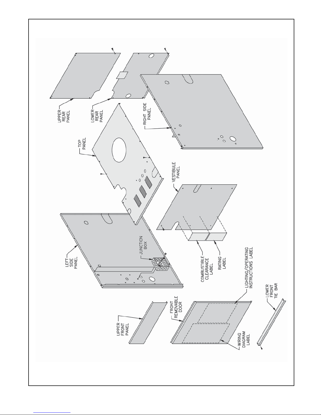
Figure 8: Jacket Assembly
13
Page 14
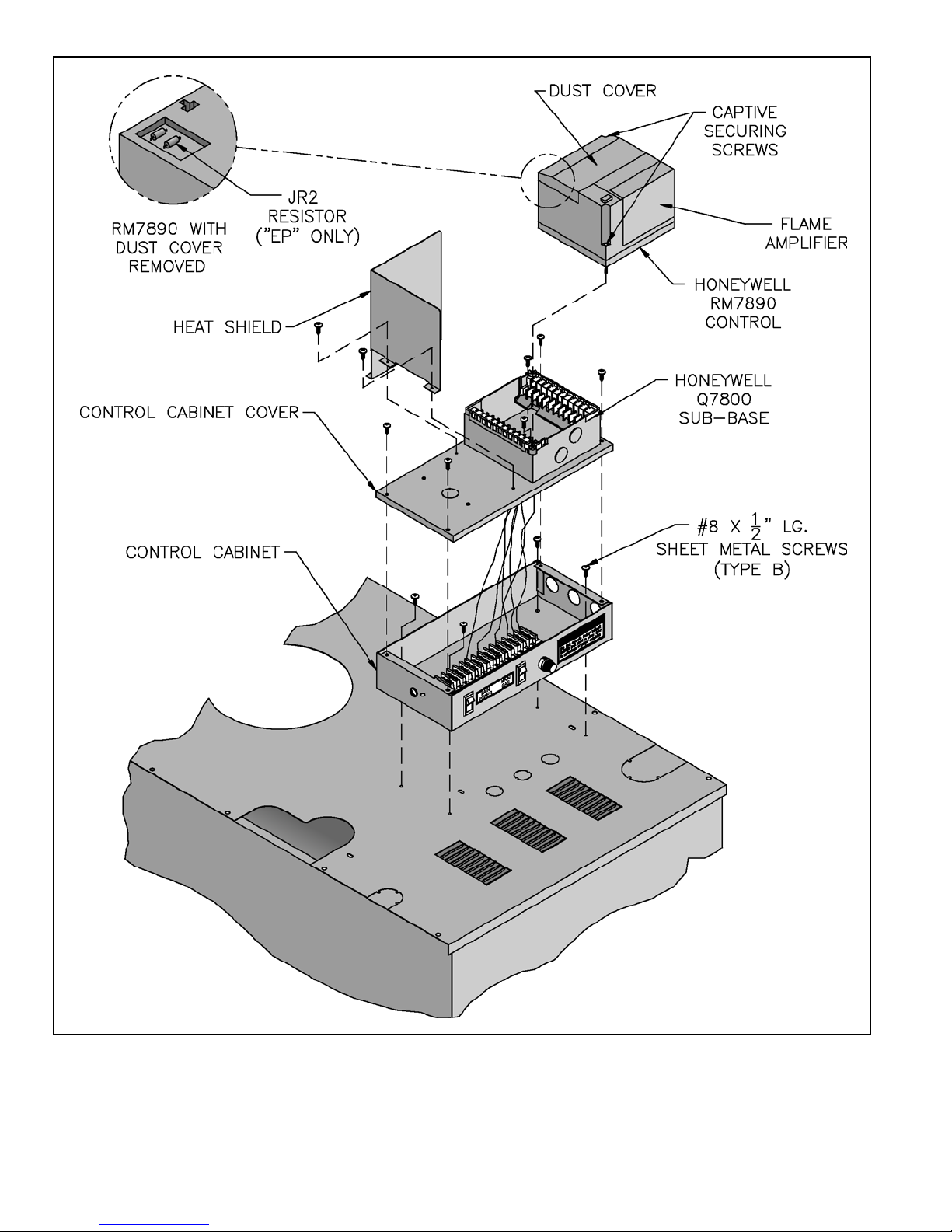
Figure 9: EP/OP Control Installation
14
Page 15

III. Gas Control System Assembly (Knockdown Boilers)
A. 24V Standing Pilot Control System
Install Gas Control System. All components are
located in Combination Boiler Parts and Control Carton.
1. Install Gas Control Assembly on Manifold. See
Figure 10. Use thread (joint) compound (pipe dope)
resistant to action of liquefied petroleum gas.
2. Install pilot burner piping and controls. See Figure
10.
3. Connect Thermocouple Lead to Gas Valve.
4. Mount Transformer (continuous circulation) or
Control Center (intermittent circulation) to Junction
Box.
a. Canada only - loop 4" nylon cable tie between
junction box and transformer/control center.
b. Attach transformer/control center to junction
box.
B. EI (Intermittent Ignition)
Install Gas Control System. All components are
located in Combination Boiler Parts and Control Carton.
1. Install Gas Control Assembly on Manifold. See
Figure 11. Use thread (joint) compound (pipe dope)
resistant to action of liquefied petroleum gas.
2. Install pilot burner piping and controls.
a. Honeywell EI
i. USA - See Figure 12.
ii. Canada - See Figure 13.
b. Johnson EI
i. USA - See Figure 14.
ii. Canada - See Figure 15.
3. Install Ignition Module.
a. Attach Ignition Control Mounting Bracket to
Jacket Vestibule Panel using two (2) #8 x ½"
sheet metal screws.
b. Attach Johnson Ignition Module to Mounting
Bracket using two (2) #6 x ¾" sheet metal screws
or attach Honeywell Ignition Module to
Mounting Bracket using two (2) #8 x ½" sheet
metal screws.
c. Connect pilot ground wire and ignitor/sensor
lead(s) to ignition module. Refer to "Section VII:
Electrical" for connection details.
4. Mount Transformer (continuous circulation) or
Control Center (intermittent circulation) to Junction
Box. See Figure 8.
a. Canada only - loop 4" nylon cable tie between
junction box and transformer/control center.
b. Attach transformer/control center to junction
box.
C. OP Control System
Install Gas Control System. All components are
located in Combination Boiler Parts and Control Carton.
1. Install Gas Control Assembly on Manifold. See
Figure 16. Use thread (joint) compound (pipe dope)
resistant to action of liquefied petroleum gas.
2. Install pilot burner piping and controls. See Figure
16.
3. Connect Thermocouple Lead to Gas Valve.
4. Mount Transformer (continuous circulation) or
Control Center (intermittent circulation) to Junction
Box.
a. Canada only - loop 4" nylon cable tie between
junction box and transformer/control center.
b. Attach transformer/control center to junction
box.
D. OP-CSD-1 Control System
Install Gas Control System. All components are
located in Combination Boiler Parts and Control Carton.
1. Install Gas Control Assembly on Manifold. See
Figure 17. Use thread (joint) compound (pipe dope)
resistant to action of liquefied petroleum gas.
2. Mount pilot switch.
3. Install pilot burner piping and controls. See Figure
17.
4. Connect Thermocouple lead to pilot switch.
5. Mount Transformer (continuous circulation) or
Control Center (intermittent circulation) to Junction
Box.
6. Attach transformer/control center to junction box.
E. EP Control System
Install Gas Control System. All components are
located in Combination Boiler Parts and Control Carton.
1. Install Gas Control Assembly on Manifold. See
Figure 18.
2. Install pilot burner piping and controls. See Figure
18.
3. Install Ignition Transformer.
a. Attach Ignition Transformer to Jacket Vestibule
Panel using four (4) #8 x ½" lg. sheet metal
screws.
b. Connect Ignition Lead from Pilot to Ignition
Transformer.
4. Mount Transformer (continuous circulation) or
Control Center (intermittent circulation) to Junction
Box.
a. Canada only - loop 4" nylon cable tie between
junction box and transformer/control center.
15
Page 16

b. Attach transformer/control center to junction
box.
Panel using four (4) #8 x ½" lg. sheet metal
screws.
F. EP-CSD-1 Control System
Install Gas Control System. All components are
located in Combination Boiler Parts and Control Carton.
1. Install Gas Control Assembly on Manifold. See
Figure 19.
2. Install pilot burner piping and controls. See Figure
19.
3. Install Ignition Transformer.
a. Attach Ignition Transformer to Jacket Vestibule
b. Connect Ignition Lead from Pilot to Ignition
Transformer.
4. Mount Transformer (continuous circulation) or
Control Center (intermittent circulation) to Junction
Box.
a. Canada only - loop 4" nylon cable tie between
junction box and transformer/control center.
b. Attach transformer/control center to junction
box.
16
Page 17
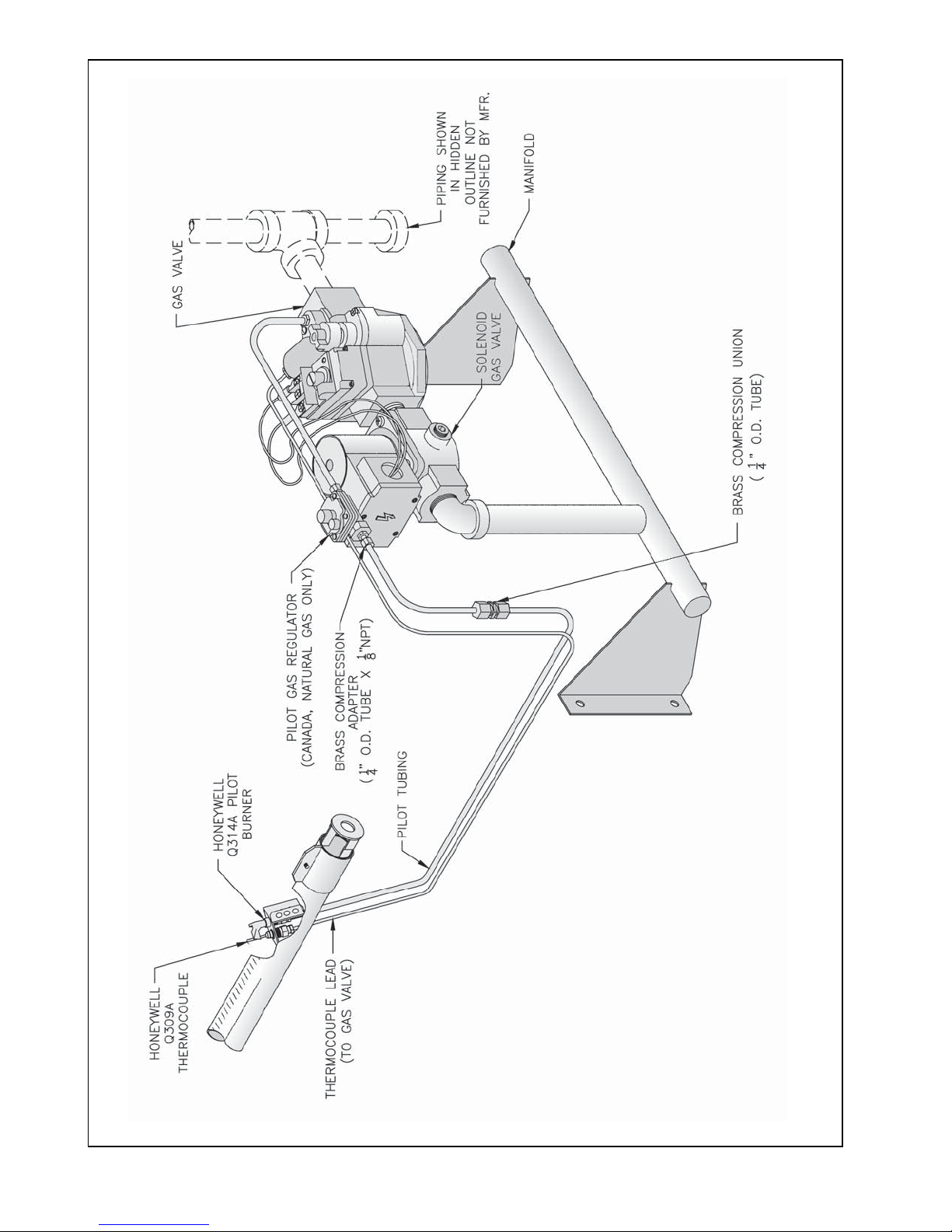
Figure 10: Schematic Gas Piping, 24V Standing Pilot, 806B & 807B
17
Page 18
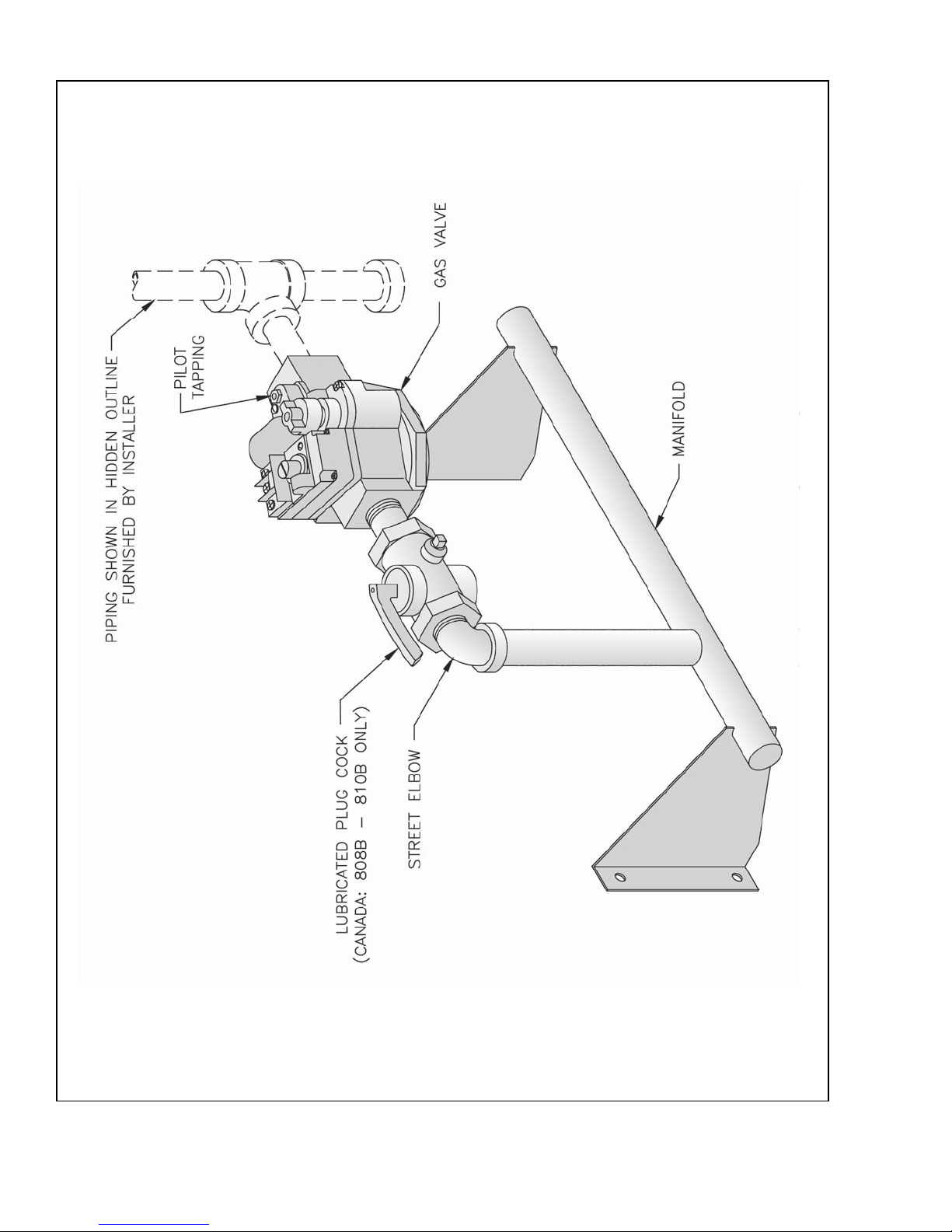
Figure 11: Main Gas Piping, Intermittent Ignition (EI)
18
Page 19
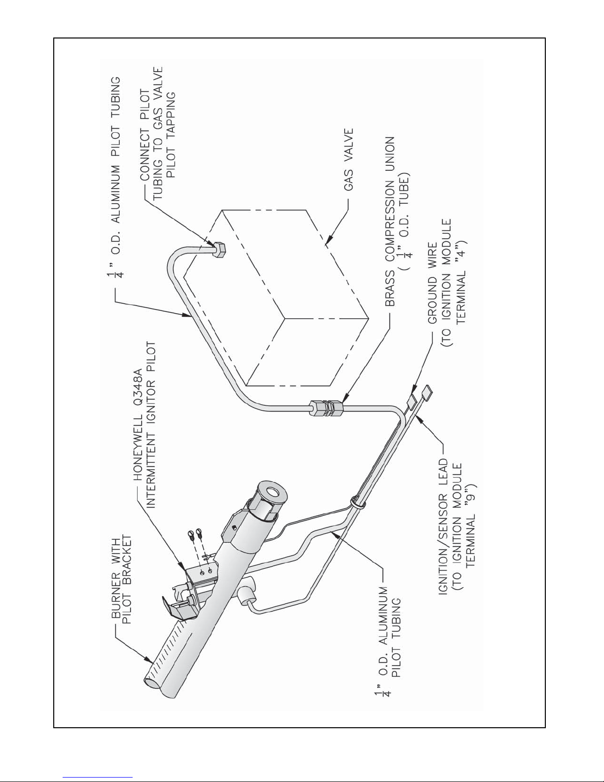
Figure 12: Schematic Pilot Piping (Honeywell EI), USA
19
Page 20
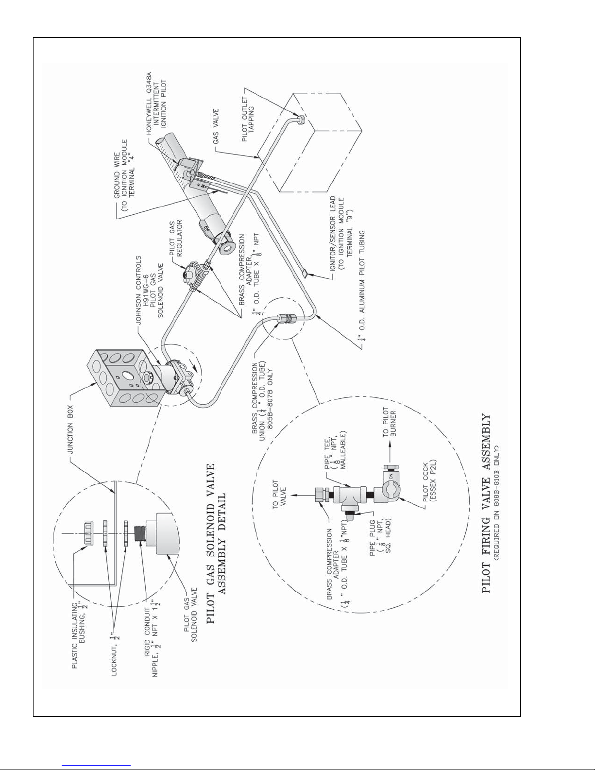
Figure 13: Schematic Pilot Piping (Honeywell EI)
Canada: Natural Gas, 805B - 810B; LP Gas, 806B - 807B
20
Page 21
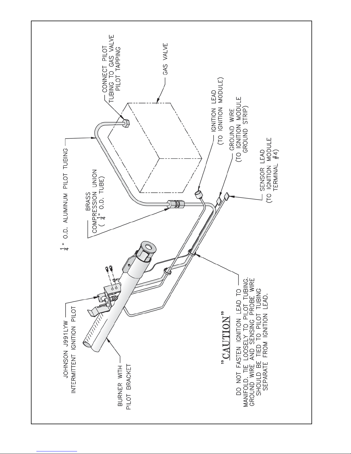
Figure 14: Schematic Pilot Piping (Johnson EI), USA
21
Page 22
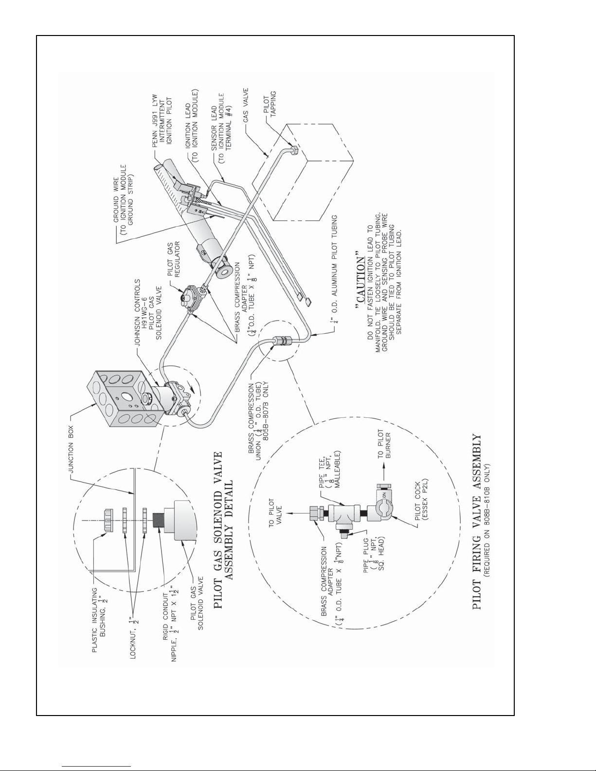
Figure 15: Schematic Pilot Piping (Johnson EI)
Canada: Natural Gas, 805B - 810B; LP Gas, 806B - 807B
22
Page 23
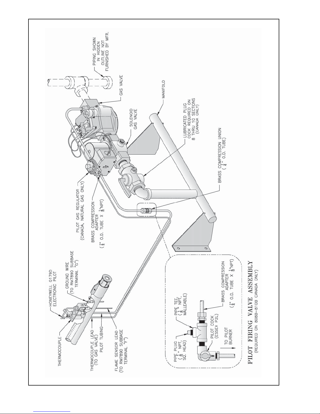
Figure 16: Schematic Gas Piping, OP Control System, 806B - 810B
23
Page 24
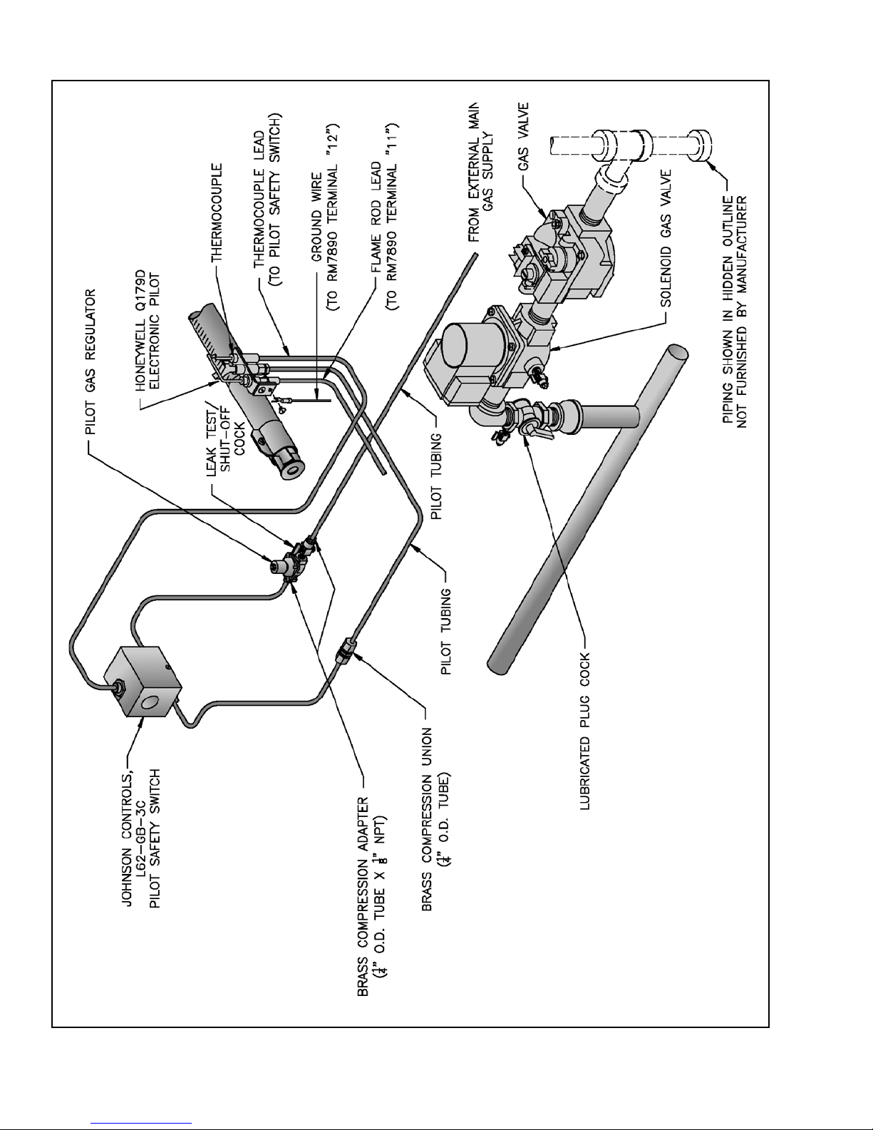
Figure 17: Schematic Gas Piping, OP-CSD-1 Control System, 808B - 810B
24
Page 25
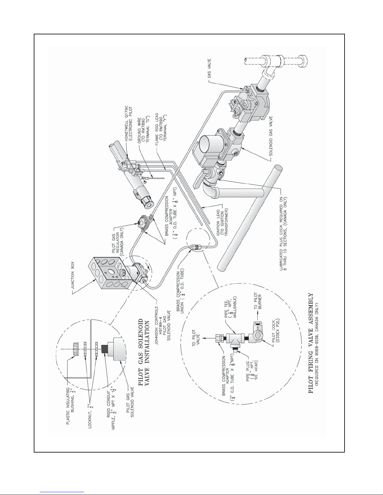
Figure 18: Schematic Gas Piping, EP Control System (Natural Gas Only), 806B - 810B
25
Page 26
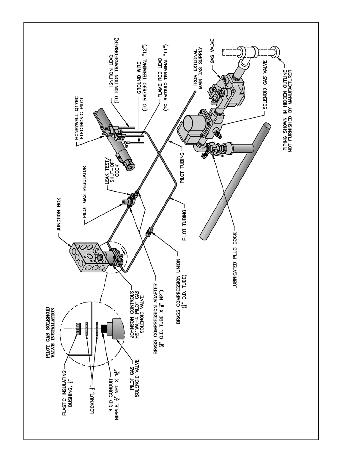
Figure 19: Schematic Gas Piping, EP-CSD-1 Control System, 808B - 810B
26
Page 27

IV. Water Trim and Piping
.erutcurts
.retawfonoitidda
GNINRAW
roreliobotegamaddnanoitareporeporpminitluseryamreliobepipylreporpoteruliaF
reliobleetsdnanorifonoisorrocesuaclliwretawreliobfonoitanimatnocnegyxO
smelborprevoctonseodytnarraWs'mahnruB.eruliafreliobotdaelnacdna,stnenopmoc
tneuqerfybdesuacpu-dliub)emil(elacsroretawreliobfonoitanimatnocnegyxoybdesuac
A. Design and install boiler and system piping to prevent
oxygen contamination of boiler water and frequent water
additions.
1. There are many possible causes of oxygen
contamination such as:
a. Addition of excessive make-up water as a result
of system leaks.
b. Absorption through open tanks and fittings.
c. Oxygen permeable materials in the distribution
system.
2. In order to insure long product life, oxygen sources
must be eliminated. This can be accomplished by
taking the following measures:
a. Repairing system leaks to eliminate the need for
addition of make-up water.
b. Eliminating open tanks from the system.
c. Eliminating and/or repairing fittings which allow
oxygen absorption.
d. Use of non-permeable materials in the
distribution system.
e. Isolating the boiler from the system water by
installing a heat exchanger.
f. Use properly designed and operating air
elimination devices in water piping.
B. Design system to obtain a 20°F temperature rise through
the boiler (see Table 4). If a temperature rise greater
than 40°F is desired, consult Burnham.
C. Install Safety Relief Valve. See Figure 20. Components
are located in Water Trim Carton. Safety Relief Valve
must be installed with spindle in vertical position.
1. Install ¾" NPT x 3½" lg. nipple in tapping "C". See
Figure 3.
2. Install safety relief valve on ¾" NPT nipple.
GNINRAW
.tnemegnarragnipip
Table 4: Flow Rate, Temperature Rise, and
Pressure Drop
RELIOB
EZIS
B508
B608
B708
B808
B908
B018
WOLF
ETAR
)MPG(
12
41
01
62
71
31
13
12
51
73
42
81
24
82
12
74
13
32
.PMET
ESIR
URHT
RELIOB
F°02
F°03
F°04
F°02
F°03
F°04
F°02
F°03
F°04
F°02
F°03
F°04
F°02
F°03
F°04
F°02
F°03
F°04
.NIM
RELIOB
GNIPIP
)TPN(
"½1
"¼1
"¼1
"½1
"½1
"¼1
"2
"½1
"¼1
"2
"½1
"½1
"2
"2
"½1
"2
"2
"½1
tsumgnipipegrahcsidevlavfeilererusserP
erevesfolaitnetopehttahthcusdepipeb
ynaniepipTONOD.detanimilesisnrub
TONOD.ruccodluocgnizeerferehwaera
.spacrosgulp,sevlavffotuhsynallatsni
egrahcsidreporprofsedoClacoLtlusnoC
RELIOB
ERUSSERP
PORD
'3
'2
'1
'3
'2
'1
'3
'2
'1
'3
'2
'1
'3
'2
'1
'3
'2
'1
27
Page 28
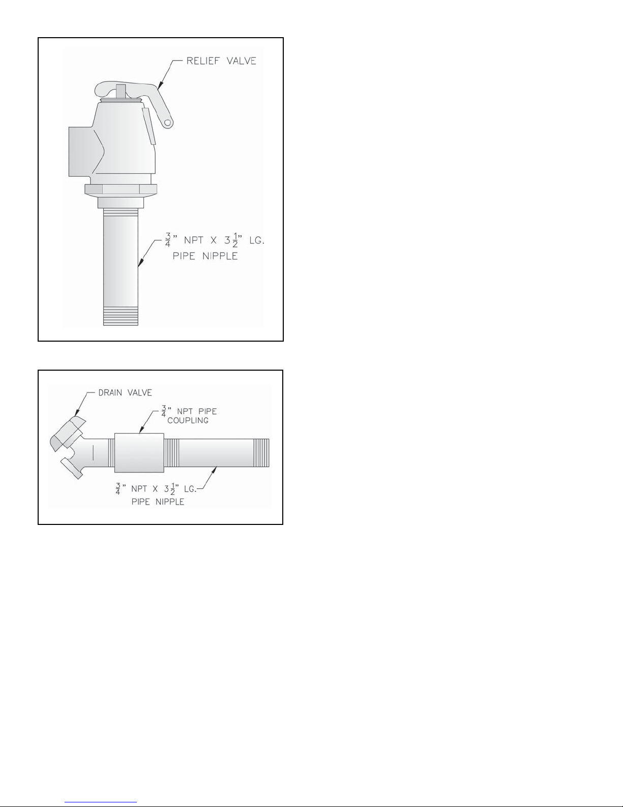
Figure 20: Safety Relief Valve Installation
Figure 21: Drain Piping Installation
b. Insert Temperature-Pressure Gauge. Tighten by
applying pressure to square shank on back of
gauge. DO NOT APPLY PRESSURE ON GAUGE
CASE since this may ruin gauge calibration.
2. Alternate Temperature-Pressure Gauge Piping. See
Figure 23.
a. Install 2 NPT x 10" Nipple into Supply Tapping
"A". See Figure 3.
b. Install 2 NPT x ¾ NPT x 2 NPT Tee (provided) or
2 NPT x 2 NPT x ¾ NPT Tee (installer furnished).
¾" NPT leg should face forward.
c. Install ¾ NPT x ¼ NPT Bushing.
d. Insert Temperature-Pressure Gauge. Tighten by
applying pressure to square shank on back of
gauge. DO NOT APPLY PRESSURE ON GAUGE
CASE since this may ruin gauge calibration.
F. Connect system supply and return piping to boiler. See
Figure 25. Also consult I=B=R Installation and Piping
Guides. Maintain minimum ½ inch clearance from hot
water piping to combustible materials.
1. If boiler is used in connection with refrigeration
systems, boiler must be installed with chilled medium
piped in parallel with heating boiler using
appropriate valves to prevent chilled medium from
entering boiler. See Figure 24. Also consult I=B=R
Installation and Piping Guides.
2. If boiler is connected to heating coils located in air
handling units where they may be exposed to
refrigerated air, boiler piping must be equipped with
flow control valves to prevent gravity circulation of
boiler water during cooling system operation.
3. Use boiler bypass if boiler is operated in system
which has a large volume or excessive radiation
where low boiler water temperatures may be
encountered (i.e. converted gravity circulation
system, etc.). See Figure 25.
4. A hot water boiler installed above radiation level
must be provided with a low water cutoff device as
part of installation.
D. Install Drain Valve in rear of Left End Section, Tapping
"G". See Figure 21. Components are located in Water
Trim Carton.
E. Install Temperature-Pressure Gauge. Components are
located in Water Trim Carton.
1. Standard Temperature - Pressure Gauge Piping. See
Figure 22.
a. Install 2" NPT x 10" lg. nipple with gauge tapping
into Supply Tapping "A". See Figure 3. Gauge
tapping should face forward.
5. A start-up strainer is recommended for practically all
modular installations (new and replacement alike) to
prevent system debris and sediment from ending up
in the boilers where it will inhibit heat transfer and
may eventually cause a cast iron section to crack
from overheating.
G. Alliance Water Heater (if used). Refer to Alliance
Installation, Operating and Service Instructions for
additional information. Install in same manner as space
heating zone.
28
Page 29
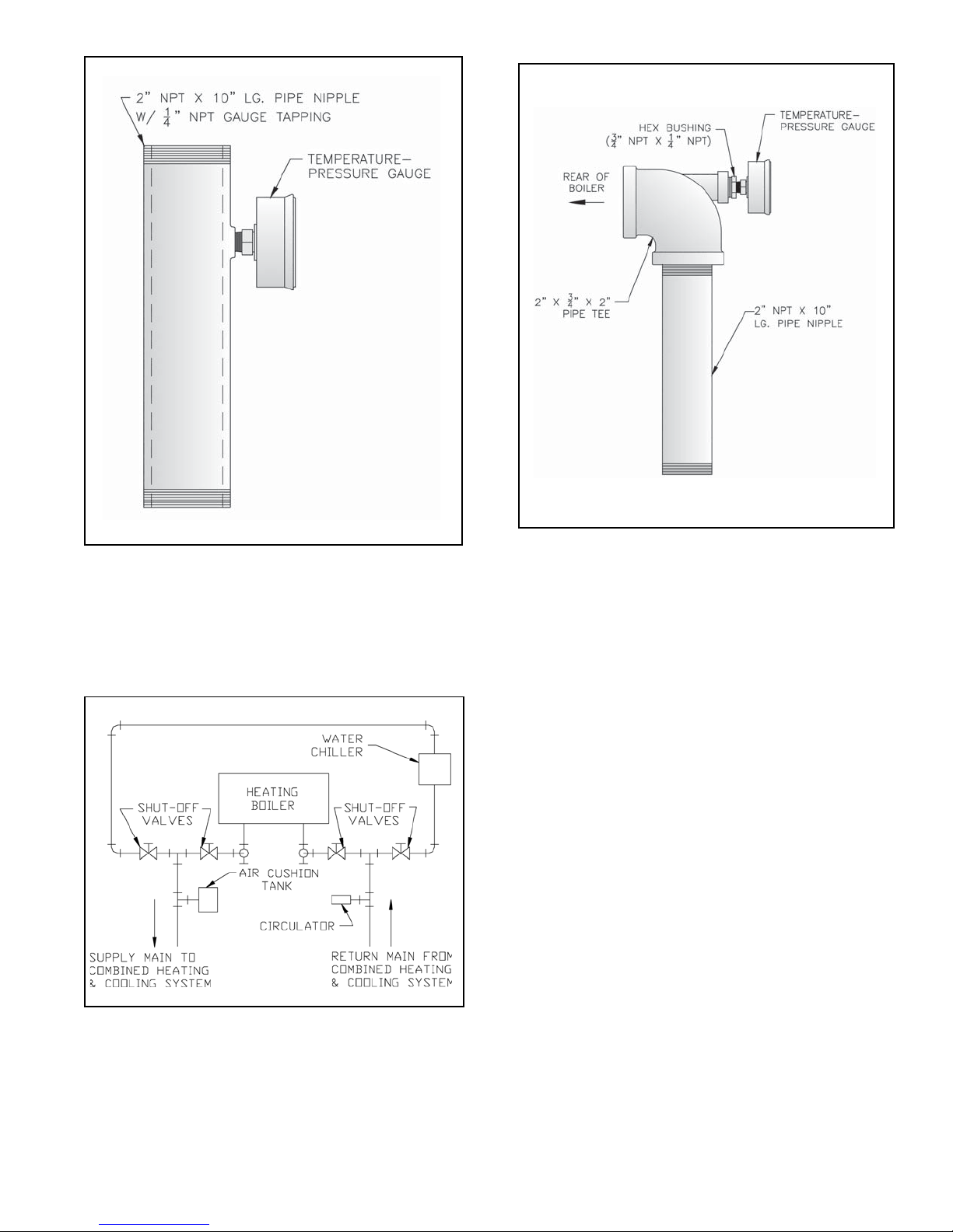
Figure 22: Temperature-Pressure Gauge
Installation
Figure 23: Alternate Temperature-Pressure
Gauge Installation
Figure 24: Recommended Piping for Combination
Heating & Cooling (Refrigeration) System
29
Page 30
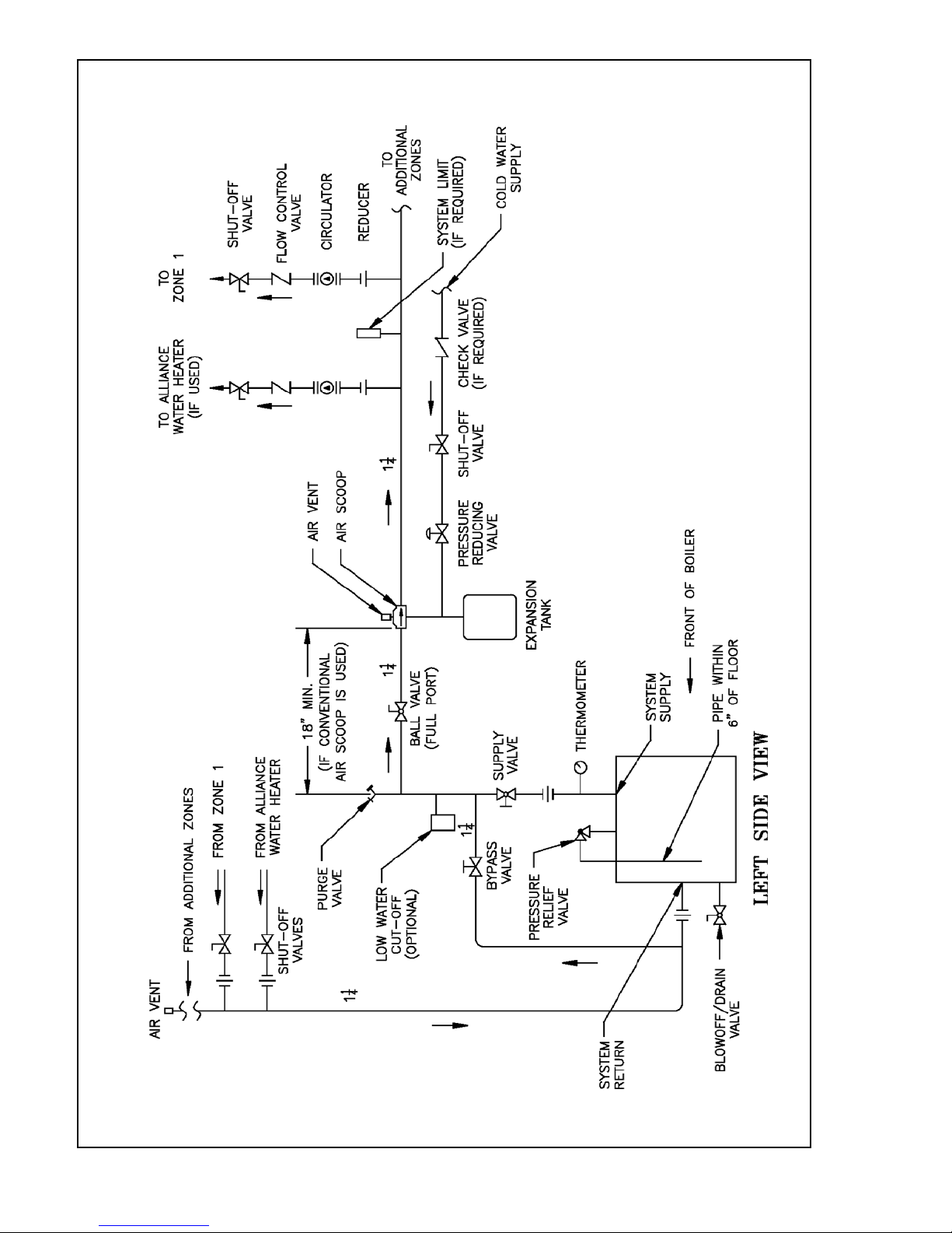
Figure 25: Recommended Boiler Piping for Circulator Zoned Heating Systems
30
Page 31

V. Gas Piping
GNINRAW
.daoldetcennoc
.reilppussagtlusnoC.dedeeneb
Size gas Piping. Design system to provide adequate
A.
gas supply to boiler. Consider these factors:
1. Allowable pressure drop from point of delivery to
boiler. Maximum allowable system pressure is ½
psig. Actual point of delivery pressure may be less;
contact gas supplier for additional information.
Minimum allowable gas valve inlet pressure is
indicated on rating label.
2. Maximum gas demand. Table 5 lists boiler input rate.
Also consider existing and expected future gas
utilization equipment (i.e. water heater, cooking
equipment)
3. Length of piping and number of fittings. Refer to
Table 6 for maximum capacity of Schedule 40 pipe.
Table 7 lists equivalent length for standard fittings.
4. Specific gravity of gas. Gas piping systems for gas
with a specific gravity of 0.70 or less can be sized
otylppussagepipylreporpoteruliaF
dnanoitareporeporpminitluseryamreliob
syawlA.erutcurtsroreliobehtotegamad
eerfkaelyletulosbasignipipsagerussa
ehtrofepytdnaezisreporpehtfodna
yamrotalugererusserpsaglanoitiddanA
directly from Table 6, unless authority having
jurisdiction specifies a gravity factor be applied. For
specific gravity greater than 0.70, apply gravity
factor from Table 8. If exact specific gravity is not
shown choose next higher value.
For materials or conditions other than those listed
above, refer to the National Fuel Gas Code, NFPA
54/ANSI Z223.1 and/or CAN/CGA B149 Installation
Codes, or size system using standard engineering
methods acceptable to authority having jurisdiction.
B. Connect boiler gas valve to gas supply system.
GNINRAW
nosdnuopmocdaerhtreporpesuoteruliaF
foskaelnitluseryamsrotcennocsaglla
.sagelbammalf
GNINRAW
ebtsummetsysdnareliobotylppussaG
rognillatsniotroirpffotuhsyletulosba
.gnipipsagreliobgnicivres
Table 5: Rated Input
relioB
ledoM
rebmuN
B5084625.5011
B6080332311
B7086935.8511
B80826457.4811
B90882552.1121
B0184955.7321
larutaNenaporP/PL
1. Use methods and materials in accordance with local
plumbing codes and requirements of gas supplier. In
absence of such requirements, follow the National
yticapaCdetaR
]ruohrepteefcibuc[
saG
noitcennoC
eziS
Fuel Gas Code, NFPA 54/ANSI Z223.1 and/or CAN/
CGA B149 Installation Codes.
2. Use thread (joint) compound (pipe dope) resistant to
action of liquefied petroleum gas.
3. Install sediment trap, ground-joint union and manual
shut-off valve upstream of boiler gas valve and
outside jacket. See Figure 26.
4. All above ground gas piping upstream from manual
gas valve must be electrically continuous and
bonded to a grounding electrode. Do not use gas
piping as a grounding electrode. Refer to the
National Electrical Code, ANSI/NFPA 70 and/or
CSA C22.1 Electrical Code.
ECITON
neebevahlevelaesevobateef000,2nahtretaergsedutitlatanoitallatsniroftliubsreliobASU
ehtreplevelaesevobateef000,1reptnecrep4etartupnisagecuderotdecifiroyllaiceps
'sreliobnaidanaC.FxidneppAdna2.1.8noitceS,1.322ZISNA/45APFN,edoCsaGleuFlanoitaN
ehtybelbaifitnedierasledomreliobedutitlahgiH.lebalgnitarehtnodetacidnisignizisecifiro
)'0005-'0002=5,'0054-'0002=4(.lebalgnitarehtnotigidhtnins'rebmunledom
31
Page 32

Table 6: Maximum Capacity of Schedule 40 Pipe in CFH for Gas Pressures of 0.5 psig or Less
htgneL
]teeF[
01231872025050,1571063086004,1
0229091053037021052564059
033725158209579002573077
043603154200528071023066
056551151204437151582085
060550159100466831062035
07646908107316521042094
08340907105375811022064
09044806102335011502034
001839705150305301591004
Table 7: Equivalent Lengths of Standard Pipe Fittings & Valves
½¾ 1 ¼1½¾1¼1
porDerusserP.c.whcni3.0porDerusserP.c.whcni5.0
)nepOylluF(sevlaVsgnittiFdedaerhT
epiP
eziS
.D.I
sehcnIetaGebolGelgnA
gniwS
kcehC
°09
woblE
°54
woblE
wolF,eeT°09
nuRhguorhT
wolF,eeT°09
hcnarBhguorhT
"½226.053.06.813.93.46.187.00.11.3
"¾428.044.01.325.113.51.279.04.11.4
"1940.165.04.927.418.66.232.18.13.5
"¼1083.147.06.833.919.85.36.13.29.6
Table 8: Specific Gravity Correction Factors
cificepS
ytivarG
05.001.103.170.1
55.040.104.140.1
06.000.105.100.1
56.069.006.179.0
07.039.007.149.0
57.009.0
08.078.0
noitcerroC
rotcaF
cificepS
ytivarG
noitcerroC
rotcaF
.ecruosnoitingirehtoro
C. Pressure Test. The boiler and its gas connection must
be leak tested before placing boiler in operation.
1. Protect boiler gas valve. For all testing over ½ psig,
boiler and its individual shut-off valve must be
disconnected from gas supply piping. For testing at
½ psig or less, isolate boiler from gas supply piping
by closing boiler's individual manual shut-off valve.
2. Locate leaks using approved combustible gas
detector, soap and water, or similar nonflammable
solution.
Figure 26: Recommended Gas Piping
32
GNINRAW
,semalfnepo,seldnac,sehctamesutonoD
Page 33

VI. Venting
A. Install vent system in accordance with local building
codes; or local authority having jurisdiction; or
National Fuel Gas Code, ANSI Z223.1/NFPA 54, Part 7,
Venting of Equipment and/or CAN/CGA B149
Installation Codes, Part 5, Venting Systems and Air
Supply for Appliances. Install any of the following for
this Series 8B Category I, draft hood equipped
appliance:
1. Type B or Type L gas vent. Install in accordance
with listing and manufacturer's instructions.
2. Masonry or metal chimney. Build and install in
accordance with local building codes; or local
authority having jurisdiction; or Standard for
Chimneys, Fireplaces, Vents, and Solid Fuel
Burning Appliances, ANSI/NFPA 211 and/or
National Building Code of Canada.
Masonry chimney must be lined with approved clay
flue lining or listed chimney lining system except as
provided in ANSI Z223.1/NFPA 54, Paragraph
7.5.4(a): Exception: Where permitted by the
authority having jurisdiction, existing chimneys
shall be permitted to have their use continued when
an appliance is replaced by an appliance of similar
type, input rating, and efficiency.
3. Single wall metal vent. Allowed by ANSI Z223.1/
NFPA 54 under very restrictive conditions.
B. Inspect chimney and remove any obstructions or
restrictions. Clean chimney if previously used for solid
or liquid fuel-burning appliances or fireplaces.
top of boiler. On Knocked Down boilers, the assembly is
located in Combination Boiler Parts and Control Carton.
1. Uncoil power cord.
2. Position mounting bracket onto lower edge of Draft
Hood skirt. Locate center tooth (with #10 sheet metal
screw) on outside and other two teeth inside Draft
Hood skirt. See Figure 27.
3. Slide mounting bracket tight against lower edge of
Draft Hood skirt. Position #10 sheet metal screw
above skirt's stiffening rib.
4. Secure bracket in position by tightening #10 sheet
metal screw against outer surface of Draft Hood
skirt.
5. Insert excess power cord through Jacket Right Side
Panel hole. Remove slack.
6. Position strain relief bushing around power cord.
Pinch bushing's two halves together and snap back
into hole in Jacket Right Side Panel.
7. Verify power cord, mounting bracket, and Blocked
Vent Switch are secure and located as shown in
Figure 27.
GNINRAW
tneVdekcolBtuohtiwreliobetarepotonoD
.dellatsniylreporphctiwS
REGNAD
gnillatsnierofebyenmihcgnitsixetcepsnI
detarofrepecalperronaelcoteruliaF.reliob
.htaed
C. Install Draft Hood on canopy outlet. Maintain height
from Jacket Top Panel to Draft Hood skirt as shown in
Figure 1. DO NOT ALTER, CUT, OR MODIFY
DRAFT HOOD.
GNINRAW
ynaecalprodoohtfardreliobretlatonoD
ehtnirepmaddevorppa-nonronoitcurtsbo
egallipssageulF.metsystnevrognihceerb
lliwnoitareporeliobefasnU.rucconac
.rucco
D. Install Blocked Vent Switch. The Blocked Vent Switch
Assembly consists of a strain relief bushing, power
cord, and switch attached to mounting bracket. On
Packaged boilers, the assembly is shipped attached to
royrujnierevesesuaclliwgninilelitroepip
Figure 27: Blocked Vent Switch Installation
33
Page 34

E. Boiler Equipped With Vent Damper. See Figure 28.
1. Open Vent Damper Carton and remove Installation
Instructions. Read Installation Instructions
thoroughly before proceeding.
NOITUAC
owtlortnocotrepmadtnevenoesutonoD
.secnailppagnitaeheromro
2. Vent damper must be same size as draft hood outlet.
See Figure 1. Unpack vent damper carefully. Forcing
vent damper open or closed may damage gear train
and void warranty. Vent damper assembly includes
pre-wired connection harness with polarized plug.
3. Mount vent damper assembly on draft hood without
modification to either (Refer to instructions packed
with vent damper for specific instructions). Vent
damper position indicator to be visible to users.
NOITUAC
-gnicivresrofecnaraelcetauqedaedivorP
neewtebecnaraelcmuminim"6edivorp
.noitcurtsnocelbitsubmocdnarepmad
F. Install Vent Connector from draft hood or vent damper
to chimney. See Figure 29. For modular or multiple
boiler installations, review "Multiple-Modular Manual
for Series 8B Gas Boilers", P/N 8141615.
1. Do not connect into same leg of chimney serving an
open fireplace.
2. Where two or more appliances vent into a common
vent, the area of the common vent should at least
equal the area of the largest vent plus 50 % of the
area of the additional vents. Do not connect the
vent of this appliance into any portion of mechanical
draft system operating under positive pressure.
3. Vent connector should have the greatest possible
initial rise above the draft hood consistent with the
head room available and the required clearance from
adjacent combustible building structure.
4. Install vent connector above bottom of chimney to
prevent blockage - inspect chimney for obstructions
or restrictions and remove - clean chimney if
necessary.
5. Vent connector should slope upward from draft
hood to chimney not less than one inch in four feet.
No portion of vent connector should run downward
or have dips or sags. Vent connector must be
securely supported.
6. Use thimble where vent connector enters masonry
chimney - keep vent connector flush with inside of
flue liner.
7. Do not install Non-listed (AGA, CGA, CSA, ETL, or
UL) vent damper or other obstruction in vent pipe.
8. Locate Boiler as close to Chimney as possible
consistent with necessary clearances. See Section I:
Pre-Installation.
Figure 28: Vent Damper Installation
34
Page 35

9. Design vent system for sea level input.
10. Provide adequate ventilation of Boiler Room. See
Section I: Pre-Installation.
11. Never pass any portion of vent system through a
circulating air duct or plenum.
G. If an Existing Boiler is Removed:
At the time of removal of an existing boiler, the
following steps shall be followed with each appliance
remaining connected to the common venting system
GNINRAW
nommoceht,metsysgnitnevnommoc
.tiotdetcennoc
placed in operation, while the other appliances
remaining connected to the common venting system are
not in operation:
1. Seal any unused openings in the common venting
system.
2. Visually inspect the venting system for proper size
and horizontal pitch and determine there is no
blockage or restriction, leakage, corrosion, or other
deficiencies which could cause an unsafe condition.
3. Insofar as is practical, close all building doors and
windows and all doors between the space in which
the appliances remaining connected to the common
venting system are located and other spaces of the
building. Turn on clothes dryers and any appliance
not connected to the common venting system. Turn
on any exhaust fans, such as range-hoods and
bathroom exhausts, so they will operate at maximum
speed. Do not operate a summer exhaust fan. Close
fireplace dampers.
4. Place in operation the appliance being inspected.
Follow the Lighting (or Operating) Instructions.
Adjust thermostat so appliance will operate
continuously.
5. Test for spillage at the draft hood relief opening after
amorfdevomersireliobgnitsixenanehW
rofegralootebotylekilsimetsysgnitnev
gniniamersecnailppaehtfognitnevreporp
5 minutes of main burner operation. Use the flame of
a match or candle, or smoke from a cigarette, cigar or
pipe.
6. After it has been determined that each appliance
remaining connected to the common venting system
properly vents when tested as outlined above,
return doors, windows, exhaust fans, fireplace
dampers and any other gas-burning appliance to
their previous condition of use.
7. Any improper operation of the common venting
system should be corrected so the installation
conforms with the National Fuel Gas Code, NFPA
54/ANSI Z223.1. When resizing any portion of the
common venting system, the common venting
system should be resized to approach the minimum
size as determined using the appropriate tables in
Part 7 and Part 11 in the National Fuel Gas Code,
NFPA 54/ANSI Z223.1.
Figure 29: Typical Vent System
35
Page 36

VII. Electrical
.mrah
REGNAD
ecivresronoitallatsnignitpmettaerofebderewopnuerasnoitcennoclacirtcelellaerussaylevitisoP
sexoblacirtcelellatuokcoL.gnidliubroreliobehtfosnoitcennocrostnenopmoclacirtcelefo
.ffodenrutsirewopecnokcoldaphtiw
GNINRAW
lacisyhpsuoiresnitluseryamreliobehtotsnoitcennoclacirtceleeriwylreporpoteruliaF
erofebffosirewopllaerusekaM.ecruosenonahterommorfebyamrewoplacirtcelE
.krowlacirtceleynagnitpmetta
.tcennocsiddesufdezisylreporpahtiwdetcetorpebtsumreliobhcaE
.slortnocgnitareporoytefasynaevitareponiekamrotuopmujreveN
reliobhcaE.ylnosesoprupecnereferroferalaunamsihtnideniatnocsmargaidgniriwehT
ehtdnamargaidsihtotrefeR.roodtnorfehtotdehcattamargaidgniriwahtiwdeppihssi
gniriwllawollofdnadnatsrednu,daeR.reliobehthtiwdesuslortnocynafomargaidgniriw
.slortnocehthtiwdeilppussnoitcurtsni
A. Install Boiler Wiring
1. Knockdown boilers only. Locate wiring harnesses in
Combination Boiler Parts and Control Carton. Refer
to Table 10 and connect wiring as shown on the
appropriate wiring diagram.
2. Connect supply wiring and electrically ground boiler
in accordance with requirements of authority having
jurisdiction, or in absence of such requirements the
National Electrical Code, ANSI/NFPA 70 and/or
CSA C22.1 Electrical Code.
B. Wire Vent Damper (if used; required on 805, optional
on 806-810). See Figure 28.
1. Attach Vent Damper Harness to mounting hole in
Jacket Left Side Panel. Install Cable Clamp around
flexible conduit and attach to Jacket Top Panel.
2. Remove factory installed Jumper Plug from Vent
Damper Receptacle on Vestibule Wiring Harness
and discard.
3. Plug Vent Damper Harness Plug into Vent Damper
Receptacle. See Figure 28.
C. Install thermostat. Locate on inside wall approximately
4 feet above floor. Do not install on outside wall, near
fireplace, or where influenced by drafts or restricted air
flow, hot or cold pipes, lighting fixtures, television, or
sunlight. Allow free air movement by avoiding
placement of furniture near thermostat.
Set heat anticipator to match control system
requirements. Refer to Table 9.
D. Wire thermostat. Provide Class II circuit between
thermostat and boiler. Refer to appropriate wiring
diagram for control system being used.
Figure 30: Vent Damper Schematic Wiring Diagram
36
Page 37

E. Alliance Water Heater (if used). May be used with
Intermittent Circulation only.
Refer to Alliance Installation, Operating and
Service Instructions for wiring, piping and
additional information.
F. Vent Damper Sequence of Operation. See Figure 30 for
schematic wiring diagram.
1. The Vent Damper is continuously powered at
Terminal 1.
2. When there is a call for heat, the damper relay coil
is energized through Terminal 5 if all limits ahead
of the damper are satisfied.
3. The relay coil closes contacts which energize the
damper motor, causing the damper to open.
4. When the damper blade reaches the fully open
position, power is sent back to the ignition circuit
through Terminal 2 and the damper motor is deenergized.
5. When the call for heat is satisfied, the damper relay
coil is de-energized - closing contacts which
energize the damper motor. This causes the damper
to close. When the damper blade reaches the fully
closed position, the damper motor is de-energized.
POWER FAILURE - The damper blade will stop in
the position it was in when power failed.
(Combustion can never take place unless the
damper blade is in the fully open position.)
G. Sequence of Operation and Wiring. Refer to Table 10
for the appropriate control system.
H. Optional Low-Water Cut-Off Wiring. See Figures 45
through 48.
Table 9: Heat Anticipator Settings
metsySlortnoC
toliPgnidnatSV421.13.0
)IE(noitingIcinortcelEV42
* ybgnittesrotapicitnataehecuder,gnitteserutarepmettatsomrehtevobadetaehsimoorfI
gnitteSrotapicitnAtaeH *
noitalucriCsuounitnoCnoitalucriCtnettimretnI
9.0:ASU
3.0
2.1:adanaC
esaercni,erutarepmetderisedgnihcaermoortuohtiwseclyctrohsreliobfI.spma2.0ro1.0
.spma2.0ro1.0ybgnittesrotapicitnataeh
37
Page 38

Table 10: Sequence of Operation and Wiring Diagrams
metsySnoitingIyrtnuoCleuFseziSrelioB
)V42(toliPgnidnatS
toliPgnidnatS
)V021--PO(
toliPgnidnatS
)V021--1-DSC-PO(
noitingItnettimretnI
)V42--IEllewyenoH(
noitingItnettimretnI
)V42--IEnosnhoJ(
noitingItnettimretnI
)V021--PE(
&ASU
adanaC
&ASU
adanaC
ASUsaGPL.tceS01-833erugiF43erugiF14egaP
ASU
adanaC
ASU
adanaC
&ASU
adanaC
saGlarutaN
saGPL
saGlarutaN
saGPL
saGlarutaN
saGPL
saGlarutaN.tceS01-5
saGPL.tceS7-5
saGlarutaN
saGPL
saGlarutaN.tceS01-5
saGPL.tceS7-5
saGlarutaN.tceS01-634erugiF44erugiF45egaP
saGPLelbaliavAtoN
erugiFmargaiDgniriW
suounitnoCtnettimretnI
.tceS7&613erugiF23erugiF83egaP
.tceS01-633erugiF43erugiF14egaP
.tceS01-553erugiF63erugiF
73erugiF83erugiF
.tceS01-593erugiF04erugiF
14erugiF24erugiF
foecneuqeS
noitarepO
44egaP
94egaP
noitingItnettimretnI
)V021--1-DSC-PE(
ASUsaGlarutaN.tceS01-834erugiF44erugiF45egaP
1. Standing Pilot (24) Sequence of Operation
a. Normal Operation
i. Thermostat or operating control calls for
heat. Vent Damper (if used) opens.
ii. Gas valves are energized allowing main gas
flow and ignition of main burners.
iii. Call or heat ends. Gas valves are de-
energized, extinguishing main flame. Vent
Damper (if used) closes.
b. Safety Shutdown
i. Limit: Automatically interrupts main burner
operation when water temperature exceeds
set point. Maximum allowable temperature is
250°F. Circulator continues to operate with
call for heat, Vent Damper (if used) closes.
Normal operation resumes when water
temperature falls below set point.
ii. Blocked Vent Switch: Automatically
interrupts main burner operation when
excessive flue gas spillage occurs. Circulator
continues to operate and Vent Damper (if
used) remains open with call for heat. If
blocked vent switch is activated do not
attempt to place boiler in operation. Correct
cause of spillage and reset blocked vent
switch.
iii. Flame Roll-out Switch: Automatically
interrupts main burner operation when
flames or excessive heat are present in
vestibule. Circulator continues to operate
and Vent Damper (if used) remains open with
call for heat. Control is single use device. If
flame roll-out switch is activated, do not
attempt to place boiler in operation. Correct
cause of spillage and replace flame roll-out
switch.
iv. Thermocouple: Senses pilot flame and
causes gas valves to turn off main burner
and pilot burner gas flow should pilot burner
flame extinguish. Circulator continues to
operate and Vent Damper (if used) remains
open with call for heat.
38
Page 39

Figure 31: Wiring Diagram, Standing Pilot (24), USA and Canada, Continuous Circulation
39
Page 40

Figure 32: Wiring Diagram, Standing Pilot (24V), USA and Canada, Intermittent Circulation
40
Page 41

2. Electronically Supervised Standing Pilot (OP)
Sequence of Operation
a. Normal Operation
i. Thermostat or operating control calls for
heat.
ii. Terminal #6 of RM7890C Burner Control is
energized, initiating a microcomputer
monitored circuit test.
iii. Pilot Flame Establishing Period (PFEP)
begins.
iv. After pilot flame is proven, terminal #9 of
RM7890C is energized, allowing main gas
flow and ignition of main burners. "Main"
gas light will be illuminated.
v. Call for heat ends. Terminal #6 of RM7890C
is de-energized, in turn de-energizing gas
valves and extinguishing main flame.
"Main" gas light is de-energized.
3. Electronically Supervised Standing Pilot (OP-CSD-1)
Sequence of Operation
a. Normal Operation
i. Thermostat or operating control calls for
heat.
ii. Terminal #6 of RM7890C Burner Control is
energized, initiating a microcomputer
monitored circuit test.
iii. Pilot Flame Establishing Period (PFEP)
begins.
iv. After pilot flame is proven, terminal #9 of
RM7890C is energized, allowing main gas
flow and ignition of main burners. "Main"
gas light will be illuminated.
v. Call for heat ends. Terminal #6 of RM7890C
is de-energized, in turn de-energizing gas
valves and extinguishing main flame.
"Main" gas light is de-energized.
b. Safety Shutdown
i. Limit: Automatically interrupts main burner
operation when water temperature exceeds
set point. Maximum allowable temperature is
250°F. Circulator continues to operate with
call for heat. Normal operation resumes
when water temperature falls below set point.
ii. Blocked Vent Switch: Automatically
interrupts main burner operation when
excessive flue gas spillage occurs. Circulator
continues to operate with call for heat. If
blocked vent switch is activated do not
attempt to place boiler in operation. Correct
cause of spillage and reset blocked vent
switch.
iii. Flame Roll-out Switch: Automatically
interrupts main burner operation when
flames or excessive heat are present in
vestibule. Circulator continues to operate
with call for heat. Control is single use
device. If flame roll-out switch is activated,
do not attempt to place boiler in operation.
Correct cause of spillage and replace flame
roll-out switch.
iv. RM7890C Burner Control: Automatically
interrupts main burner operation if a pilot
flame is not detected during the four or ten
second pilot flame establishing period. The
RM7890C will lockout or recycle based on
jumper settings. "Alarm" light will be
illuminated. Refer to instructions supplied
with RM7890C for additional control
information.
v. Pilot Safety Switch: Automatically de-
energizes main gas valve and interrupts pilot
gas supply if pilot flame is not detected at
any time.
41
Page 42

Figure 33: Wiring Diagram, OP/OP-CSD-1 Ignition System, Continuous Circulation
42
Page 43

Figure 34: Wiring Diagram, OP/OP-CSD-1 Ignition System, Intermittent Circulation
43
Page 44

4. Honeywell EI Sequence of Operation
a. Normal Operation
i. Thermostat or operating control calls for
heat. Vent Damper (if used) opens.
ii. Ignition Module Terminals PV, MV/PV
and the Ignition Terminal are energized.
Terminals PV and MV/PV power the Pilot
Valve in the Gas Valve supplying gas to the
Pilot. The Ignition Terminal supplies
voltage to the Ignition Electrode creating an
electric spark to ignite the Pilot.
iii. The sensing Circuit between the Q348 Pilot
Burner and the IGNITION MODULE
proves the presence of the Pilot Flame
Electronically and the Ignition Terminal is
de-energized.
iv. Terminals MV and MV/PV of the
IGNITION MODULE are energized and
supply power to the Main Gas Valve. The
Gas Valve is energized allowing main gas
flow, and ignition of Main Burners.
v. Call for heat ends. Ignition module is de-
energized, de-energizing gas valve, and
extinguishing pilot and main flame. Vent
Damper (if used) closes.
b. Safety Shutdown
i. Limit: Automatically interrupts power to
the Ignition Module and Gas Valve(s),
extinguishing pilot and main flame, when
water temperature exceeds set point.
Maximum allowable temperature is 250°F.
Circulator continues to operate with call for
heat, Vent Damper (if used) closes. Normal
operation resumes when water temperature
falls below set point.
ii. Blocked Vent Switch: Automatically
interrupts main burner operation when
excessive flue gas spillage occurs.
Circulator continues to operate and Vent
Damper (if used) remains open with call for
heat. If blocked vent switch is activated do
not attempt to place boiler in operation.
Correct cause of spillage and reset blocked
vent switch.
iii. Flame Roll-out switch: Automatically
interrupts main burner operation when
flames or excessive heat are present in
vestibule. Circulator continues to operate,
Vent Damper (if used) remains open with
call for heat. Control is single use device.
If flame roll-out switch is activated, do not
attempt to place boiler in operation.
Correct cause of spillage and replace flame
roll-out switch.
iv. Pilot
– Pilot failure can occur during the start-up or
the operating cycle of the boiler. Any pilot
failure of the Q348 Electronic Pilot, after
ignition of pilot flame will close the main
gas valve in 0.8 seconds.
– For approximately 90 seconds after failure
of the Q348 pilot, the module through the
ignition terminal will try to reestablish pilot
flame. If no pilot flame can be sensed by
the flame rod circuit, terminals PV and
MV/PV are de-energized and the module
will lock out on safety. Five to six minutes
after shutdown, the IGNITION MODULE
restarts the ignition sequence. The ignition
trial, shutdown, and wait sequence
continues until either the pilot lights or the
Thermostat is set below room temperature
(to end the call for heat). The ignition
sequence can be reset by setting down the
Thermostat for one minute.
c. Trouble Shooting Guide. See Page 71.
44
Page 45

Figure 35: Wiring Diagram, Honeywell EI, USA, Continuous Circulation
45
Page 46

Figure 36: Wiring Diagram, Honeywell EI, USA, Intermittent Circulation
46
Page 47

Figure 37: Wiring Diagram, Honeywell EI, Canada, Continuous Circulation
47
Page 48

Figure 38: Wiring Diagram, Honeywell EI, Canada, Intermittent Circulation
48
Page 49

5. Johnson EI Sequence of Operation
a. Normal Operation
i. Thermostat or operating control calls for
heat. Vent Damper (if used) opens.
ii. Ignition Module Terminals 1, GND and the
Ignition Terminal are energized. Terminals 1
and GND power the Pilot Valve in the Gas
Valve supplying as to the Pilot. The Ignition
Terminal supplies voltage to the Ignition
Electrode creating an electric spark to ignite
the Pilot.
iii. The sensing Circuit between the J991 Pilot
Burner and the IGNITION MODULE proves
the presence of the Pilot Flame electronically
and the Ignition Terminal is de-energized.
iv. Terminals 3 and GND of the IGNITION
MODULE are energized and supply power to
the Main Gas Valve. The Gas Valve is
energized allowing main gas flow, and
ignition of Main Burners.
v. Call for heat ends. Ignition module is de-
energized, de-energizing gas valve, and
extinguishing pilot and main flame. Vent
Damper (if used) closes.
b. Safety Shutdown
i. Limit: Automatically interrupts power to the
Ignition Module and Gas Valve(s),
extinguishing pilot and main flame, when
water temperature exceeds set point.
Maximum allowable temperature is 250°F.
Circulator continues to operate with call for
heat, Vent Damper (if used) closes. Normal
operation resumes when water temperature
falls below set point.
ii. Blocked Vent Switch: Automatically
interrupts main burner operation when
excessive flue gas spillage occurs. Circulator
continues to operate, Vent Damper (if used)
remains open with call for heat. If blocked
vent switch is activated do not attempt to
place boiler in operation. Correct cause of
spillage and reset blocked vent switch.
iii. Flame Roll-out switch: automatically
interrupts main burner operation when
flames or excessive heat are present in
vestibule. Circulator continues to operate,
Vent Damper (if used) remains open with call
for heat. Control is single use device. If
flame roll-out switch is activated, do not
attempt to place boiler in operation. Correct
cause of spillage and replace flame roll-out
switch.
iv. Pilot:
– Pilot failure can occur during the start-up
or the operating cycle of the boiler. Any
pilot failure of the J991 Electronic Pilot, after
ignition of pilot flame will close the main gas
valve.
– For approximately 90 seconds after failure
of the J991 pilot, the module through the
ignition terminal will try to reestablish pilot
flame. If no pilot flame can be sensed by the
flame rod circuit, terminals 1 and GND are deenergized and the module will lock out on
safety. Five to six minutes after shutdown,
the IGNITION MODULE restarts the ignition
sequence. The ignition trial, shutdown, and
wait sequence continues until either the pilot
lights or the Thermostat is set below room
temperature (to end the call for heat). The
ignition sequence can be reset by setting
down the Thermostat for one minute.
c. Trouble Shooting Guide. See Pages 72 and 73.
49
Page 50

Figure 39: Wiring Diagram, Johnson EI, USA, Continuous Circulation
50
Page 51

Figure 40: Wiring Diagram, Johnson EI, USA, Intermittent Circulation
51
Page 52

Figure 41: Wiring diagram, Johnson EI, Canada, Continuous Circulation
52
Page 53

Figure 42: Wiring Diagram, Johnson EI, Canada, Intermittent Circulation
53
Page 54

6. Electronically Supervised Intermittent Ignition
(EP/EP-CSD-1) Sequence of Operation
a. Normal Operation
i. Thermostat or operating control calls for
heat.
ii. Terminal #6 of RM7890A Burner Control is
energized, initiating a microcomputer
monitored circuit test.
iii. The pilot valve (terminal 8) and ignition
transformer (terminal 10) are energized. The
pilot valve opens and the ignition electrode
sparks, igniting the pilot.
iv. After the pilot flame is proven, the ignition
terminal (10) is de-energized and the main
valve terminal (9) is energized, allowing main
gas flow and ignition of main burners.
"Main" gas light will be illuminated.
v. When the call for heat ends, terminal #6 is
de-energized, extinguishing the pilot and
main flames. "Main" gas light is deenergized.
b. Safety Shutdown
i. Limit: Automatically interrupts main burner
operation when water temperature exceeds
set point. Maximum allowable temperature is
250°F. Circulator continues to operate with
call for heat. Normal operation resumes
when water temperature falls below set point.
ii. Blocked Vent Switch: Automatically
interrupts main burner operation when
excessive flue gas spillage occurs. Circulator
continues to operate with call for heat. If
blocked vent switch is activated, do not
attempt to place boiler in operation. Correct
cause of spillage and reset blocked vent
switch.
iii. Flame Roll-out Switch: Automatically
interrupts main burner operation when flames
or excessive heat are present in vestibule.
Circulator continues to operate with call for
heat. Control is single use device. If flame
roll-out switch is activated, do not attempt to
place boiler in operation. Correct cause of
spillage and replace flame roll-out switch.
iv. RM7890A Burner Control: Automatically
interrupts main burner operation if a pilot
flame is not detected during the four or ten
second pilot flame establishing period. The
RM7890A will lockout or recycle based on
jumper settings. "Alarm" light will be
illuminated. Refer to instructions supplied
with RM7890A for additional control
information.
54
Page 55

Figure 43: Wiring Diagram, EP/EP-CSD-1 Ignition System, USA, Continuous Circulation
55
Page 56

Figure 44: Wiring Diagram, EP/EP-CSD-1 Ignition System, USA, Intermittent Circulation
56
Page 57

Figure 45: McDonnell & Miller PS-851 (120V) L.W.C.O. Wiring for Boilers with 24V Limit Circuits
Figure 46: McDonnell & Miller PS-851 (120V) L.W.C.O. Wiring for Boilers with 120V Limit Circuits (OP & EP)
57
Page 58

Figure 47: Hydrolevel OEM - 170/550/650/750 (120V) L.W.C.O. Wiring for Boilers with 24V Limit Circuits
Figure 48: Hydrolevel OEM - 170/550/650/750 (120V) L.W.C.O. Wiring for Boilers with 120V Limit Circuits
58
Page 59

VIII. System Start-up
GNINRAW
llawollofdnadnatsrednu,daeryletelpmoC
erofeblaunamsihtnisnoitcurtsni
.putratsgnitpmetta
A. Safe operation and other performance criteria were met
with the gas manifold and control assembly provided
on boiler when boiler underwent tests specified in
American National Standard for Gas-Fired LowPressure Steam and Hot Water Boilers, ANSI Z21.13.
B. Check Main Burners. Main burners must be properly
located on support bracket in Base Rear Panel, seated
on Main Burner Orifices, and secured with hitch pin
clips.
C. Verify that the venting, water piping, gas piping and
electrical system are installed properly. Refer to
installation instructions contained in this manual.
D. Confirm all electrical, water and gas supplies are
turned off at the source and that vent is clear of
obstructions.
E. FILL ENTIRE HEATING SYSTEM WITH WATER
and vent air from system. Use following procedure on a
Series Loop or multi-zoned system installed as per
Figure 25 to remove air from system when filling.
GNINRAW
sihtfoerusserpgnitarepomumixamehT
.erusserpsihtdeecxereveN.gisp05sireliob
.evlavfeilererusserpyfidomrogulptonoD
At completion, open all zone valves or shut-off
valves.
9. Close purge valve, continue filling the system until
the pressure gauge reads the desired cold fill
pressure. Close fill valve.
(Note - If make-up water line is equipped with
pressure reducing valve, adjust pressure reducing
valve to desired cold fill pressure. Follow fill valve
manufacturer’s instructions).
10. Open isolation valve in boiler supply piping.
11. Remove hose from purge valve.
F. Confirm that the boiler and system have no water leaks.
G. Prepare to check operation.
1. Obtain gas heating value (in Btu per cubic foot) from
gas supplier.
2. Connect manometer to pressure tap on gas valve.
Use 1/8 NPT tapping provided.
3. Temporarily turn off all other gas-fired appliances.
4. Turn on gas supply to the boiler gas piping.
5. Confirm that the supply pressure to the gas valve is
14 in. w.c. or less.
6. Open the field installed manual gas shut-off valve
located upstream of the gas valve on the boiler.
7. Using soap solution, or similar non-combustible
solution, electronic leak detector or other approved
method. Check that boiler gas piping, valves, and
all other components are leak free. Eliminate any
leaks.
8. Purge gas line of air.
1. Close full port ball valve in boiler supply piping.
2. Isolate all zones by closing zone valves or shut-off
valves in supply and return of each zone(s).
3. Attach a hose to the vertical purge valve located
prior to the full port ball valve in the system supply
piping. (Note - Terminate hose in five gallon
bucket at a suitable floor drain or outdoor area).
4. Starting with one circuit at a time, open zone valve
or shut-off valve in system supply and return
piping.
5. Open purge valve.
6. Open fill valve (Make-up water line should be
located directly after full port ball valve in system
supply piping between air scoop and expansion
tank).
7. Allow water to overflow from bucket until
discharge from hose is bubble free for 30 seconds.
8. Close the open zone valve or shut-off valve for the
zone being purged of air, then open the zone valve
or shut-off valve for the next zone to be purged.
Repeat this step until all zones have been purged.
REGNAD
H. Follow Lighting or Operating Instructions to place boiler
in operation. Refer to label on inside of Front Removable
Panel or appropriate Figure as listed in Table 11.
Table 11: Lighting and Operating Instructions
rognithgiL
metsySnoitingI
toliPgnidnatS
)V42(
IEllewyenoH
IEnosnhoJ65erugiF
PO15erugiF75erugiF
PE25erugiF85erugiF
1-DSC-PO
1-DSC-PE85erugiF
59
gnitarepO
snoitcurtsnI
94erugiF45erugiF
05erugiF
35erugiF
rosemalfnepo,seldnac,sehctamesutonoD
.skaelrofkcehcotecruosnoitingirehto
emalFtoliP
noitartsullI
55erugiF
75erugiF
Page 60

Figure 49: Lighting Instructions (24V Standing Pilot)
60
Page 61

Figure 50: Operating Instructions (EI)
61
Page 62

Figure 51: Lighting Instructions (OP)
62
Page 63

Figure 52: Operating Instructions (EP)
63
Page 64

.1tolipdna)s(evlavffo-tuhsniamlaunamesolC
.2.hctiwscirtceleniamffonruT
.1tolipehtdnalaunamniamehthtobtahterusekaM
.2otslortnocgnitarepolladnatatsomrehtmoornruT
.3.)s(lenapsseccarenrubevomeR
SNOITCURTSNIGNITAREPORELIOB
:NWODTUHSOT
.)s(evlav
:PUTRATSOT
.setunimeviftsaeltarofffoneebevah)s(evlav
.gnittestsewol
.4
:ETON
.5dnahctiwsytefastolipgnidnatsnonottubsserpeD
.6.hctiwscirtceleniamnonruT
.7.yalerdraugefasemalfnohctiwsytefasteseR
.8noitacifitcergninrubtnatsnocthgilyletaidemmI
.a8)s(tolipnoitacifitcernoitingicirtceletnettimretnI
.9.)s(lenapsseccarenrubecalpeR
.)s(evlavtoliplaunamnepO
tolpgnidnatshtiwsreliobotylnoseilppa)5(metI
.)se(hctiwsytefas
tarofninottubgnidloh,tolipothctamdethgildloh
retfadethgilsniamertoliplitnuroetunimenotsael
gnidnatsgniniamerroftaepeR.desaelersinottub
.stolip
tonsitolipfI.hctamdethgilahtiwD971Q)s(tolip
.detaeperebtsum)7(petS,sdnoces51nidethgil
retfagninepo,citamotuaera)s(evlavtolipcirtcelE
.)metsyS"PO"(.)7(petS
rotatsomrehtnehwyllacitamotuaputhgilC971Q
.)metsyS"PE"(.taehrofsllaclortnocgnitarepo
.01.)s(evlavff-tuhsniamlaunamnepO
.11otslortnocgnitarepodnatatsomrehtmoortsujdA
Figure 53: Lighting / Operating Instructions (OP/EP-CSD-1)
.gnittesderised
64
Page 65

Figure 54: Honeywell Q314 Pilot Flame
(24V Standing Pilot)
Figure 57: Honeywell Q179D Pilot Flame (OP)
Figure 55: Honeywell Q348 Pilot Flame
(24V Electronic Ignition)
Figure 56: Johnson J991 Pilot Flame
(24V Electronic Ignition)
Figure 58: Honeywell Q179C Pilot Flame (EP)
I. Check pilot burner flame and main burner flames
through observation port.
1. Check pilot flame. Refer to Table 11 for appropriate
pilot detail.
2. Adjust thermostat to highest setting.
3. Check main burner flames. See Figure 59. Flame
should have clearly defined inner cones with no
yellow tipping. Orange-yellow streaks caused by
dust should not be confused with true yellow
tipping.
65
Page 66

NOITUAC
tnemnorivnenanireliobsihtgnitarepodiovA
yrd,srebifnoitalusniesool,tsudwaserehw
sireliobfI.tneserpera.cte,tsudllaw
renrubeht,snoitidnocesehtrednudetarepo
dnadenaelcebtsumstropdnaroiretni
.noitareporeporperusniotyliaddetcepsni
Yellow-tipping indicates lack of primary air. Improper
burner alignment on Main Burner Orifice will also
affect primary air injection. Adjust primary air as
follows:
a. Loosen lock screw.
b. Close air adjustment until yellow tips appear on
flames.
Figure 59: Main Burner Flame
c. Slowly open air adjustment until clearly defined
inner cones are visible.
d. Tighten lock screw.
4. Adjust thermostat to normal setting.
J. Check thermostat or operating control operation.
Raise and lower temperature setting to start and stop
boiler operation.
K. Check ignition system shut-off.
1. Standing Pilot (24V): Disconnect thermocouple
lead at Gas Valve. Gas Valve must close and pilot
and main burners extinguish. If not, replace the
gas valve.
2. Honeywell EI: Disconnect ignitor/sensor cable
from Terminal (9) of ignition module. Gas valve
must close and pilot and main burners extinguish.
If not, measure voltage across gas valve terminals
"TH" and "TR".
a. If voltage is not present, replace gas valve.
b. If voltage is present, replace ignition module.
3. Johnson EI: Disconnect sensor cable from
Terminal 4 (SENSE). Gas valve must close and
pilot and main burner extinguish. If not, measure
voltage across gas valve terminals "TH" and "TR".
a. If voltage is not present, replace gas valve.
b. If voltage is present, replace ignition module.
4. EP and OP: Refer to instructions supplied with the
Honeywell RM7890 Burner Control.
L. Check Limit(s).
1. Adjust thermostat to highest setting.
2. Observe temperature gauge. When temperature
exceeds limit set point main burners should
extinguish.
3. Adjust limit to setting above observed reading. Main
burners should reignite.
4. Adjust thermostat to lowest setting. Adjust limit to
desired setting.
M. Adjust gas input rate to boiler. Natural Gas.
1. Adjust thermostat to highest setting.
2. Check manifold gas pressure. Manifold pressure is
listed on rating label. Adjust gas valve pressure
regulator as necessary (turn adjustment screw
counterclockwise to decrease manifold pressure, or
clockwise to increase manifold pressure). If
pressure can not be attained, check gas valve inlet
pressure. If less than minimum gas supply pressure
listed on rating label, contact gas supplier for
assistance.
3. Clock gas meter for at least 30 seconds. Use Table
12 to determine gas flow rate in Cubic Feet per
Hour.
4. Determine Input Rate. Multiply gas flow rate by gas
heating value.
GNINRAW
lliwetartupnisagtsujdaylreporpoteruliaF
ehtfognirifrednurognirifrevonitluser
reliobefasnudnareporpmI.ecnailppa
.tluseryamnoitarepo
5. Compare measured input rate to input rate stated on
rating label.
a. Boiler must not be overfired. Reduce input rate
by decreasing manifold pressure. Do not reduce
more than 0.3 inch w.c. If boiler is still
overfired, contact your Burnham distributor or
Regional Office for replacement Gas Orifices.
66
Page 67

b. Increase input rate if less than 98% of rating plate
input. Increase manifold gas pressure no more
than 0.3 inch w.c. If measured input rate is still
less than 98% of rated input:
i. Remove Main Burners per procedure in
Section IX: Service.
ii. Remove gas orifices. Drill one (1) drill size
larger (drill size is stamped on orifice, or
see Key No. 4E).
iii. Reinstall gas orifices and main burners.
Measure input rate.
6. Recheck Main Burner Flame.
7. Return other gas-fired appliances to previous
conditions of use.
N. Adjust gas input rate to boiler. LP/Propane.
1. Set thermostat to highest setting.
2. Adjust tank regulator for gas valve inlet pressure of
13.5 inches w.c. or less.
3. Gas valve has step opening regulator which initially
opens to 1.4 or 2.5 inch w.c. and steps to full
pressure after approximately 30 seconds. Check
manifold pressure after step has occurred. Adjust
gas valve pressure regulator as necessary for 10.0
inches w.c. (turn adjustment screw
counterclockwise to decrease manifold pressure, or
clockwise to increase manifold pressure). If 10.0
inches w.c. can not be attained, check gas valve
inlet pressure. If less than 11.0 inches w.c., contact
gas supplier for assistance.
O. Clean Heating System
Oil, grease, and other foreign materials which
accumulate in new hot water boilers and a new or
reworked system should be boiled out, and then
thoroughly flushed. A qualified water treatment
chemical specialist should be consulted for
recommendations regarding appropriate chemical
compounds and concentrations which are compatible
with local environmental regulations.
P. Check Damper Operation - If boiler is equipped with
vent damper, vent damper must be in open position
when boiler main burners are operating. Start boiler,
refer to instructions on damper to determine if damper
is in full open position.
Q. Install Front Removable Panel.
1. Engage top flange (longer of 2 flanges) behind
Upper Front Panel.
2. Swing lower portion of door toward boiler.
3. Lower door to engage bottom flange behind Lower
Front Tie Bar.
Table 12: Input Rate
sdnoceS
enOrof
noituloveR
0306021042006
2365311522365
4335601212925
6305001002005
837459981474
045409081054
243468271034
441428461014
649387751193
847357051573
056327441063
255396831643
453376331333
652346921123
851326421013
060306021003
269285611092
469265211182
669245901372
868235601562
076215301752
275205001052
47428479342
67427459732
87326429132
08225409522
flaH-enO
.tF.uC
enO
.tF.uC
owT
.tF.uC
R. Combustion Chamber Burn-Off
1. The mineral wool combustion chamber panels
contain a cornstarch based binder that must be
burned out at installation to prevent odors during
subsequent boiler operation.
2. Ventilate the boiler room, set the high limit to its
maximum setting, set the thermostat to call for
heat.
3. Allow the boiler to fire for at least an hour or until
the odor from the cornstarch has dissipated.
4. Return the high limit and thermostat to their
desired settings.
S. Review User's Information Manual and system
operation with owner or operator.
laiDreteMsaGfoeziS
eviF
.tF.uC
67
Page 68

IX. Service
GNINRAW
amorflennosrepdelliksdnadeniartybylnonekatrednuebdluohsreliobsihtnoecivreS
sihtnideificepsslavretnitademrofrepebdluohssnoitcepsnI.ycnegaecivresdeifilauq
.noitidnocelbigelanilaunamniatniaM.launam
elbammalfrehtodnaenilosag,slairetamelbitsubmocfoeerfdnaraelcaerareliobpeeK
.sdiuqildnasropav
dnanoitsubmocfowolfrednihlliwtahtmoorreliobnisnoitcurtsboynaecalptonoD
.rianoitalitnev
snoitcurtsniehtotnoitiddanieralaunamsihtnideniatnocsnoitcurtsniecivresehT
s'rerutcafunamtnenopmocwolloF.stnenopmocreliobehtforerutcafunamehtybdedivorp
.reliobehthtiwdedivorperewsnoitcurtsnis'rerutcafunamtnenopmoC.snoitcurtsni
,llatsnitonoD.gnissimerasnoitcurtsnifitnemecalperrofrerutcafunamtnenopmoctcatnoC
follagnidnatsrednudnagnidaertuohtiwreliobsihtecivresroniatniam,etarepo,putrats
detcennocsid,deretlahtiwetarepootreliobehtwollatonoD.snoitcurtsnitnenopmoceht
yllanigiroesohtotlacitnedistnenopmoctnemecalperesuylnO.stnenopmocderepmujro
.mahnruBybdeilppus
A. General. Inspection and service must be conducted
annually. Turn off electrical power and gas supply
while conducting service or maintenance. Follow
instructions TO TURN OFF GAS TO APPLIANCE.
See Lighting/Operating Instructions on inside of Front
Removable Door.
GNINRAW
nehwnoitcennocsidotroirpseriwllalebaL
esuacnacsrorregniriW.slortnocgnicivres
yfireV.noitareposuoregnaddnareporpmi
.gnicivresretfanoitareporeporp
B. Maintenance of Low Water Cut-off (if used). Follow
instructions provided with low water cut-off.
C. Vent System. Check for:
1. obstructions
2. accumulations of soot
3. deterioration of vent pipe or vent accessories due to
condensation or other reasons
4. proper support—no sags, particularly in horizontal
runs
5. tightness of joints. Remove all accumulations of
soot with wire brush and vacuum
Remove all obstructions. Replace all deteriorated parts
and support properly. Seal all joints.
D. Remove Main Burners for cleaning, changing orifice
plugs, or repairs.
1. Shut down gas boiler in accordance with Lighting/
Operating Instructions on inside of Front
Removable Door. Close Manual Shut-off Valve.
2. Remove Front Removable Door. Raise Lower Front
Tie Bar.
3. Disconnect ignition system.
4. Remove burner access panel(s).
5. Mark location of Main Burner with Pilot Bracket on
manifold.
6. Remove hitch pin clips from Main Burner Orifices.
7. Hold Main Burner on throat. Lift slightly to raise rear
of burner. Push to rear of boiler until burner clears
Main Burner Orifice. Lift burners out.
8. Check burners to be sure they do not contain foreign
matter or restrictions. Clean burners with a soft
bristle brush, blow any dirt out with compressed air
or use a vacuum cleaner. See Figure 60.
E. Clean Boiler Flueways.
1. Shut down gas boiler in accordance with Lighting/
Operating Instructions on inside of Front
Removable Door. Close Manual Shut-off Valve.
2. Disconnect vent system. Remove Draft Hood.
3. Remove Jacket Top Panel.
4. Remove Canopy from top of boiler.
5. Thoroughly clean flueways with flue brush,
removing all scale and soot. See Figure 60.
6. Clean boiler heating surface accessible from
combustion chamber with straight handle wire
brush.
7. Install Canopy. See Section II: Boiler Assembly,
Paragraph G.
8. Install Jacket Top Panel, Draft Hood, Vent Damper
(if used) and Vent System.
68
Page 69

noitamrofnIytefaStcudorPtnatropmI
tcudorPrebiFcimareCyrotcarfeR
Warning:
This product contains refractory ceramic fibers (RCF). RCF has been classified
as a possible human carcinogen. After this product is fired, RCF may, when
exposed to extremely high temperature (>1800F), change into a known human
carcinogen. When disturbed as a result of servicing or repair, RCF becomes
airborne and, if inhaled, may be hazardous to your health.
AVOID Breathing Fiber Particulates and Dust
Precautionary Measures:
Do not remove or replace previously fired RCF (combustion chamber insulation,
target walls, canopy gasket, flue cover gasket, etc.) or attempt any service or
repair work involving RCF without wearing the following protective gear:
1. A National Institute for Occupational Safety and Health (NIOSH)
approved respirator
2. Long sleeved, loose fitting clothing
3. Gloves
4. Eye Protection
• Take steps to assure adequate ventilation.
• Wash all exposed body areas gently with soap and water after contact.
• Wash work clothes separately from other laundry and rinse washing
machine after use to avoid contaminating other clothes.
• Discard used RCF components by sealing in an air tight plastic bag.
First Aid Procedures:
• If contact with eyes: Flush with water for at least 15 minutes. Seek
immediate medical attention if irritation persists.
• If contact with skin: Wash affected area gently with soap and water.
Seek immediate medical attention if irritation persists.
• If breathing difficulty develops: Leave the area and move to a location
with clean fresh air. Seek immediate medical attention if breathing
difficulties persist.
• Ingestion: Do not induce vomiting. Drink plenty of water. Seek
immediate medical attention.
69
Page 70
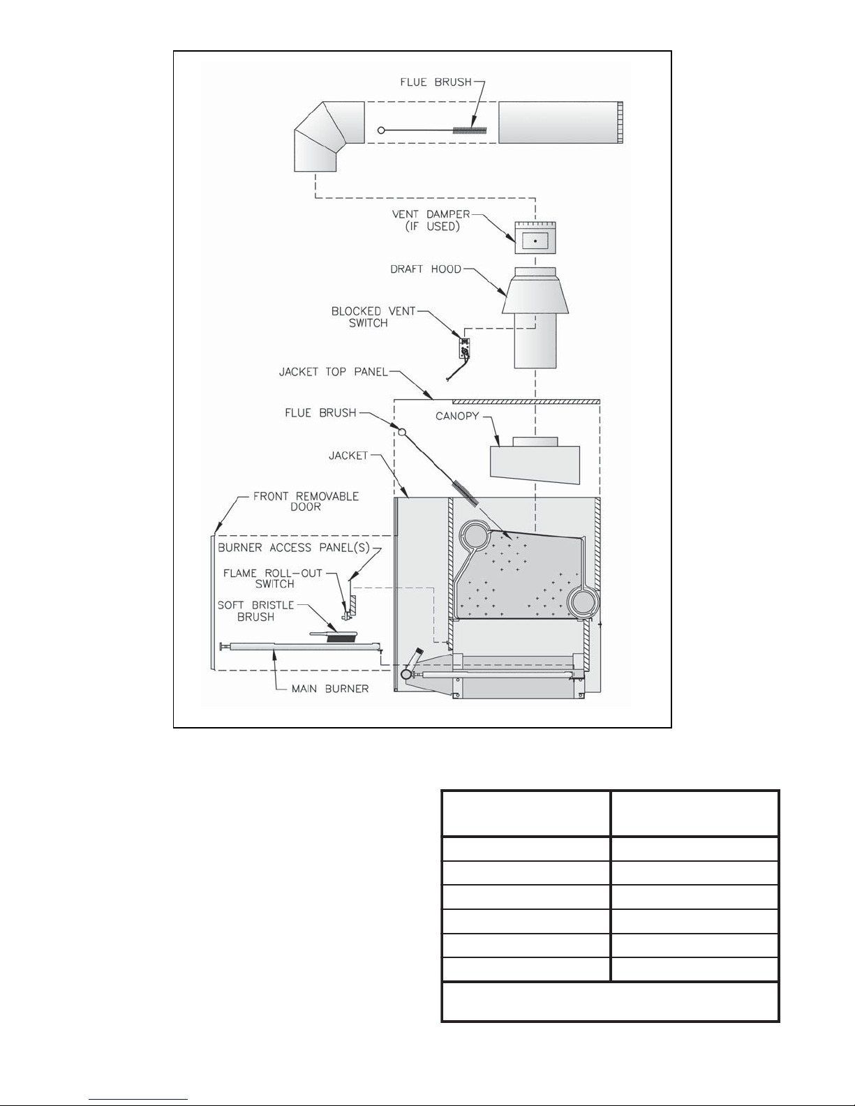
Figure 60: Boiler Flueway Cleaning
F. Clean Combustion Chamber by vacuuming. Exercise
care to avoid damaging Base Insulation.
G. Install Burners by reversing procedures used to
remove burners. Verify Main Burners are properly
located on support bracket in Base Rear Panel, seated
on Main Burner Orifices, and secured with hitch pin
clips. Verify Main Burner with Pilot Bracket is in
proper location. See Table 13.
H. Lubrication. Manufacturers Instruction should be
followed on all parts installed on boiler requiring
lubrication. This includes type of lubricant to be used,
frequency of lubrication, and points to lubricate.
I. Check operation. Refer to Section VIII: System Start-
up.
Table 13: Pilot Burner Location
B5085&4
B6086&5
B7087&6
B8087&6
B9087&6
B0188&7
.reliobfo
70
.oNledoMrelioB
*srenruB
neewteBdetacoLtoliP
tnorfmorfdeweivsathgirottfelderebmunsrenruB*
Page 71

Honeywell EI Trouble Shooting Guide
71
Page 72

Johnson EI Trouble Shooting Guide
72
Page 73
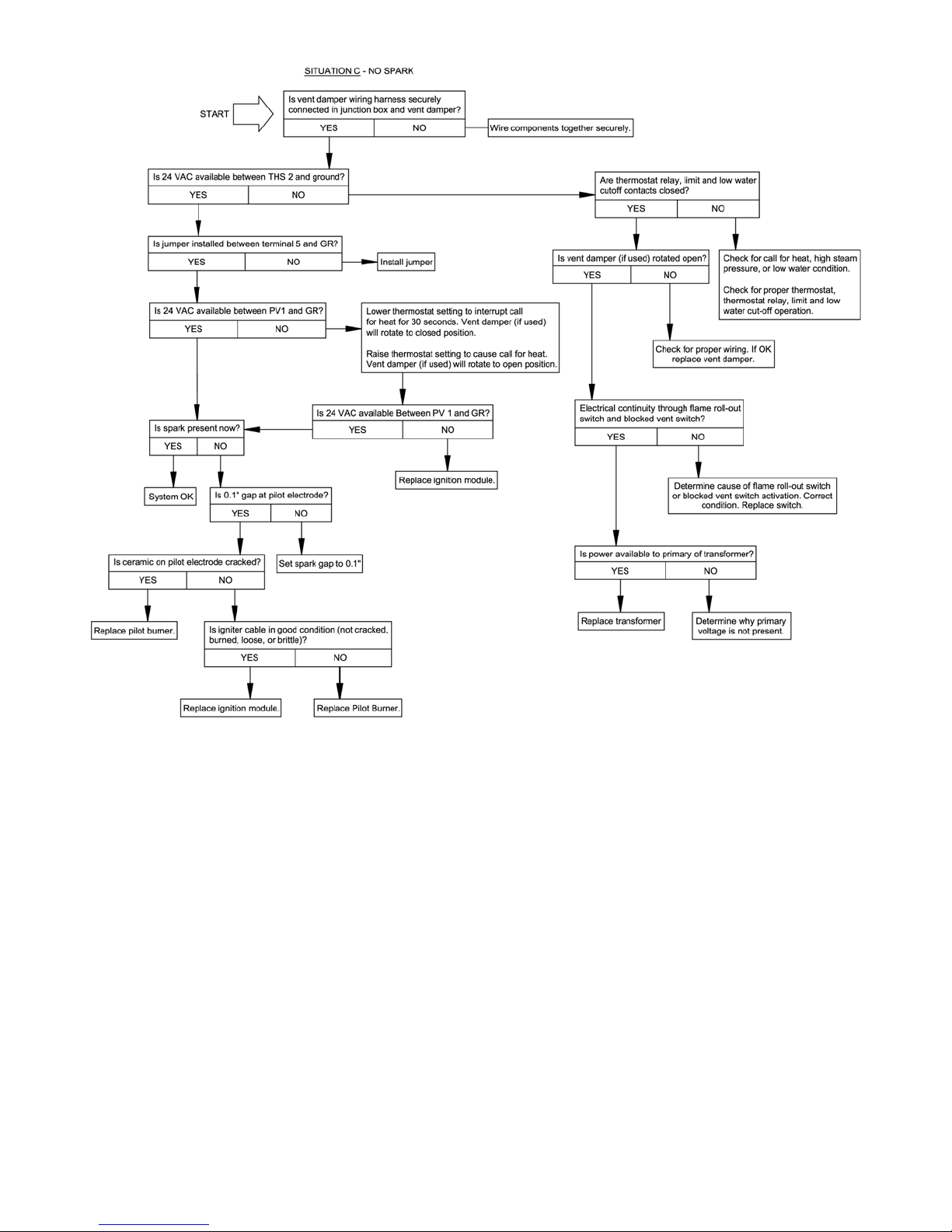
73
Page 74

SERVICE RECORD
DATE SERVICE PERFORMED
74
Page 75

SERVICE RECORD
DATE SERVICE PERFORMED
X. Repair Parts
All Series 8B Repair Parts may be obtained through your local Burnham Wholesale distributor. Should you require assistance
in locating a Burnham Distributor in your area, or have questions regarding the availability of Burnham products or repair
parts, please contact Burnham Customer Service at (717) 481-8400 or Fax (717) 481-8408.
75
Page 76

metI
.oN
noitpircseD.oNtraP
B508B608B708B808B908B018
ytitnauQ
ylbmessAregnahcxEtaeH.1
50617161--------------6061716---1-----------7061716------1---------
1etelpmoC
8061716---------1-----9061716------------1---
0161716---------------1
A1noitceSdnEtfeL1061717 111111
B1noitceSetaidemretnI3061717345678
C1noitceSdnEthgiR2061717 111111
doReiT230168081--------------doReiT33016808---1------------
D1
E1rehsaW00606808 444444
F1tuN00406808 444444
G1"3,elppiNpilS200660780121416181
doReiT31016808------1--------doReiT43016808---------1-----doReiT53016808------------1--doReiT63016808---------------1
76
Page 77

metI
.oN
noitpircseD.oNtraP
B508B608B708B808B908B018
ytitnauQ
yponaC.2
50611161-------------------6061116----1----------------
A2yponaC
B2"1x02-¼,egairraC,tloB51106808 222222
C2talF"¼,rehsaW30606808 222222
D202-"¼,tuN70406808 222222
7061116--------1-----------8061116------------1-------9061116----------------1---0161116--------------------1
77
Page 78

metI
.oN
noitpircseD.oNtraP
B508B608B708B808B908B018
ytitnauQ
.3ylbmessAesaB
A3lenaPdnEesaB1061817222222
250618162--------------26061816---2------------
B3ylbmessAlennahCesaB
C3ylbmessAlenaPraeResaB
D3ylbmessAlenaPtnorFesaB
E3ylbmessAlenaPsseccArenruB
F3tekcarBtnemhcattAtekcaJ1061407444444
G3"¼1x02-¼,egairraC,tloB60106808444444
H3talF"¼,rehsaW30606808444444
J302-¼,tuN70406808444444
K3"½x02-¼,gnippaTfleS,wercS00706808344556
27061816------2--------28061816---------2-----29061816------------2--20161816---------------2
150618161--------------16061816---1-----------17061816------1--------18061816---------1-----19061816------------1--10161816---------------1
350618161--------------36061816---1-----------37061816------1--------38061816---------1-----39061816------------1--30161816---------------1
450618161--------------46061816---1-----------47061816------1--------48061816---------2-----49061816------------2--40161816---------------2
L3"¾x81-"61/5,daeHxeH,paC,wercS20316808222222
M3"¼1x81-"61/5,daeHxeH,paC,wercS11316808666666
N3"½x8#,lateMteehS,wercS00006808888888
P3talF"8/3,rehsaW00606808666666
Q381-"61/5,tuN30406808666666
R3"¾x02-¼,gnippaTfleS,wercS20706808010101010101
78
Page 79

metI
.oN
noitpircseD.oNtraP
B508B608B708B808B908B018
ytitnauQ
.4srenruBniaMdnadlofinaM
A4renruBniaM206132880121517191
gnidnatS,tekcarBtoliPhtiwrenruBniaM
)V42(toliP
IEllewyenoH,tekcarBtoliPhtiwrenruBniaM
B4
PO,tekcarBtoliPhtiwrenruBniaM
PE,tekcarBtoliPhtiwrenruBniaM
C4dlofinaM
D4)C4htiwdedulcnI(TPN8/1,gulPepiP--- 111111
E4
F4pilCniPhctiH40622891131618102
IEnosnhoJ,tekcarBtoliPhtiwrenruBniaM
*)ylnOsaGlarutaN(73#,ecifirOrenruBniaM106228
*)ylnOenaporP/PL(25#,ecifirOrenruBniaM146228
1061328---11111
4061328 111111
3061328---11111
150612281--------------16061228---1-----------17061228------1--------18061228---------1-----19061228------------1--10161228---------------1
91131618102
* .yrotcaftlusnocedutitlAhgiHroF.)teef0002-0(edutitlalamronrofnwohssezisecifirorenrubniaM
79
Page 80

METI
.ON
NOITPIRCSED
TRAP
REBMUN
EZISYTITNAUQ
)PO,V42(toliPgnidnatS--niarTsaG1-5
saGPL&larutaN,noitceS7&6,adanaC&ASU:V42
saGPL&larutaN,noitceS01-6,adanaC&ASU:PO
A
TPN"¾,4201A5928VllewyenoH,evlaVsaGdioneloS 53206618B708-B608
B
TPN"1,2301A5928VllewyenoH,evlaVsaGdioneloS 63206618B018-B808
C TPN"1,M002nekilliM-namweN,evlaVffO-tuhSlaunaMdetacirbuL 916228
DTPN"¾xTPN"1,gnihsuBxeH 105006608B708&B6081
.gL"2xTPN"¾,elppiN 300006608B708&B6081
E
.gL"2xTPN"1,elppiN 400006608B018-B808
TPN"¾xTPN"1,woblEteertS 215106608B708&B608
F
TPN"1xTPN"¼1,woblEteertS 315106608B018-B808
TPN"1,saGlarutaN,C7S-CHRE0007wahstreboR,evlaVsaG 65106618
TPN"1,saGPL,C7S-PL-CHRE0007wahstreboR,evlaVsaG 75106618
B018-B6081
1
B018-B808
ylnOadanaC
1
1:ASU
2:adanaC
1
80
Page 81

METI
.ON
NOITPIRCSEDREBMUNTRAPYTITNAUQ
)1-DSC-PO(toliPgnidnatS--niarTsaG2-5
ylnOsaGPL,noitceS01,ylnOASU:1-DSC-PO
ATPN"1,saGPL,C7S-CHREVG0007wahstreboR,evlaVsaG 172066181
BTPN"1,2301A5928VllewyenoH,evlaVsaGdioneloS 632066181
CdetacirbuLffO-tuhSlaunaMevlaVTPN"1,20-304-05#oCarBnoC,5162281
D"8/1x"8/1,10-122-65#oCarBnoC,evlaVffo-tuhS/tseTkaeL 9762282
E"8/1,gulPepiP 4953066082
F"8/1x"4/1,gnihsuBxeH 0250066081
GgnoL"2x"1,elppiN 4000066082
H"1x°09,woblEteertS 4151066081
J"1,elppiNesolC 3300066081
K"1x"4/1-1,gnilpuoCelbaellaM 2052066081
LevlaVdioneloSotevlaVsaG,ssenraHgniriW 03263161
M424493#llewyenoH,gulPteltuOtoliP 15062281
81
Page 82

METI
.ON
NOITPIRCSED
)IE(noitingItnettimretnI-niarTsaG3-5
saGPLdnalarutaN,noitceS01-5:ASU
saGlarutaN,noitceS01-5:adanaC
saGPL,noitceS7-5
TPN"1,saGlarutaN,CHRED0007wahstreboR,evlaVsaG 15106618B018-B508
A
BacirbuLTPN"1,M002nekilliM-namweN,evlaVffO-tuhSlaunaMdet 916228
C.gL"2xTPN"1,elppiN 400006608
TPN"1,saGPL,PL-CHRED0007wahstreboR,evlaVsaG 85106618
TRAP
REBMUN
EZISYTITNAUQ
B018-B508:ASU
B708-B508:adanaC
B018-B808
ylnOadanaC
1
1
D
TPN"1,woblEteertS 415106608B708-B508
1
TPN"1xTPN"¼1,woblEteertS 315106608B018-B808
82
Page 83

METI
.ON
NOITPIRCSED
TRAP
REBMUN
EZISYTITNAUQ
)PE(noitingItnettimretnI-niarTsaG4-5
ylnOsaGlarutaN,noitceS01-6:adanaC&ASU
A TPN"1,saGlarutaN,C7S-CHREVG0007wahstreboR,evlaVsaG 86106618B018-B6081
B
C TPN"1,M002nekilliM-namweN,evlaVffO-tuhSlaunaMdetacirbuL 916228
DTPN"¾xTPN"1,gnihsuBxeH 105006608B708&B6081
.gL"2xTPN"¾,elppiN 300006608B708&B6081
E
.gL"2xTPN"1,elppiN 400006608B018-B808
TPN"¾xTPN"1,woblEteertS 215106608B708&B608
F
TPN"1xTPN"¼1,woblEteertS 315106608B018-B808
TPN"¾,4201A5928VllewyenoH,evlaVsaGdioneloS 53206618B708-B608
TPN"1,2301A5928VllewyenoH,evlaVsaGdioneloS 63206618B018-B808
1
B018-B808
ylnOadanaC
1
1:ASU
2:adanaC
1
83
Page 84

METI
.ON
NOITPIRCSEDREBMUNTRAPYTITNAUQ
)1-DSC-PE(noitingItnettimretnI-niarTsaG5-5
ylnOsaGlarutaN,noitceS01-8,ylnOASU
ATPN"1,saG.taN,C7S-CHREVG0007wahstreboR,evlaVsaG 861066181
BTPN"1,2301A5928VllewyenoH,evlaVsaGdioneloS 632066181
CdetacirbuLffO-tuhSlaunaMevlaVTPN"1,20-304-05#oCarBnoC,5162281
D"8/1x"8/1,10-122-65#oCarBnoC,evlaVffo-tuhS/tseTkaeL 9762282
E"8/1,gulPepiP 4953066082
F"8/1x"4/1,gnihsuBxeH 0250066081
GgnoL"2x"1,elppiN 4000066082
H"1x°09,woblEteertS 4151066081
J"1,elppiNesolC 3300066081
K"1x"4/1-1,gnilpuoCelbaellaM 2052066081
LevlaVdioneloSotevlaVsaG,ssenraHgniriW 03263161
M424493#llewyenoH,gulPteltuOtoliP 15062281
84
Page 85

METI
.ON
NOITPIRCSED
TRAP
REBMUN
EZISYTITNAUQ
)V42(toliPgnidnatS--gnipiPdnaylbmessAtoliP6-5
saGPLdnalarutaN,noitceS7&6:adanaC&ASU
A
BdaeL.gL"63/w6991A903QllewyenoH,elpuocomrehT4006328
CebuTDO"¼,noinUnoisserpmoCssarB8006328B708&B6081
DsaGlarutaN,TL21VRlortixaM,rotalugeR5006228
ETPN"8/1xebuTDO"¼,retpadAnoisserpmoCssarB036228
saGlarutaN,7863A413QllewyenoH,renruBtoliP3306328
llA1saGPL,8283A413QllewyenoH,renruBtoliP4306328
B708&B608:adanaC
ylnOsaGlarutaN
B708&B608:adanaC
ylnOsaGlarutaN
1
2
85
Page 86
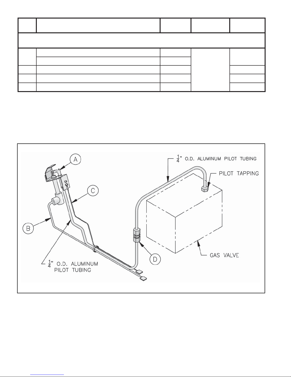
METI
.ON
NOITPIRCSED
TRAP
REBMUN
EZISYTITNAUQ
ASU)IEllewyenoH(noitingItnettimretnI-gnipiPdnaylbmessAtoliP7-5
saGPLdnalarutaN,noitceS01-5
A
B2-308493llewyenoH,.gL"63,elbaCrosneS/retingI 12163281
CylbmessAeriWdnuorG 45063161
DebuTDO"¼,noinUnoisserpmoCssarB 80063281
saGlarutaN,2001A843QllewyenoH,renruBtoliP U2706328
1
saGPL,0101A843QllewyenoH,renruBtoliP 1806328
B018-B508
86
Page 87

METI
.ON
NOITPIRCSED
TRAP
REBMUN
EZISYTITNAUQ
adanaC)IEllewyenoH(noitingItnettimretnI--gnipiPdnaylbmessAtoliP8-5
saGlarutaN,noitceS01-5
saGPL,noitceS7-5
A
B63-008493llewyenoH,.gL"63,elbaCrosneS/retingI4806328
CylbmessAeriWdnuorG4506316
DebuTDO"¼,noinUnoisserpmoCssarB8006328B708-B5081
EL2PxessE,evlaVffo-tuhS546228
GdaeH.qS,TPN"8/1,gulPepiP805306608
HTPN"8/1xebuTDO"¼,retpadAnoisserpmoCssarB036228
J6-GW19HnosnhoJ,evlaVsaGdioneloS666228
L.gL"½1xTPN"½,elppiNtiudnoCdigiR9106318
M"½,tunkcoLtiudnoC02263182
N"½,gnihsuBgnitalusnIcitsalP43063181
PsaGlarutaN,TL21VRlortixaM,rotalugeR5006228
saGlarutaN,2001A843QllewyenoH,renruBtoliPU2706328B018-B508
saGPL,0101A843QllewyenoH,renruBtoliP1806328B708-B508
1
llA1
B018-B8081FelbaellaM,TPN"8/1,eeTepiP500106608
saGlarutaNB708-B5082
saGlarutaNB018-B8083
saGPLB708-B5081
1KpeeD"½1x.qS"4,xoBnoitcnuJ9526318
llA
B018-B508
ylnOsaGlarutaN
1
87
Page 88

METI
.ON
NOITPIRCSED
TRAP
REBMUN
EZISYTITNAUQ
ASU)IEnosnhoJ(noitingItnettimretnI--gnipiPdnaylbmessAtoliP9-5
saGPLdnalarutaN,noitceS01-5
saGlarutaN,5227WYL199JnosnhoJ,renruBtoliP
)daeLnoitingIsedulcnI(
A
saGPL,D0489WYL199JnosnhoJ,renruBtoliP
)daeLnoitingIsedulcnI(
BC-AA57YnosnhoJ,eborPgnisneS 04063281
C63-HA75YnosnhoJ,daeLrosneS 15063281
DylbmessAeriWdnuorG 45063161
EebuTDO"¼,noinUnoisserpmoCssarB 80063281
0506328
1
6806328
B018-B508
88
Page 89

METI
.ON
NOITPIRCSED
TRAP
REBMUN
EZISYTITNAUQ
adanaC)IEnosnhoJ(noitingItnettimretnI--gnipiPdnaylbmessAtoliP01-5
saGlarutaN,noitceS01-5
saGPL,noitceS7-5
A
BC-AA57YnosnhoJ,eborPgnisneS 0406328
C63-HA75YnosnhoJ,daeLrosneS 15063281
DylbmessAeriWdnuorG 45063161
EebuTDO"¼,noinUnoisserpmoCssarB 8006328B708-B5081
FL2PxessE,evlaVffo-tuhS 546228
GelbaellaM,TPN"8/1,eeTepiP 5001066081
HdaeH.qS,TPN"8/1,gulPepiP 8053066081
JTPN"8/1xebuTDO"¼,retpadAnoisserpmoCssarB 036228
K6-GW19HnosnhoJ,evlaVsaGdioneloS 666228
LpeeD"½1x.qS"4,xoBnoitcnuJ 95263181
M.gL"½1xTPN"½,elppiNtiudnoCdigiR 91063181
N"½,tunkcoLtiudnoC 02263182
P"½,gnihsuBgnitalusnIcitsalP 43063181
QsaGlarutaN,TL21VRlortixaM,rotalugeR 5006228
)daeLnoitingIsedulcnI(
)daeLnoitingIsedulcnI(
saGlarutaN,5227WYL199JnosnhoJ,renruBtoliP
saGPL,D0489WYL199JnosnhoJ,renruBtoliP
0506328B018-B508
6806328B708-B508
1
1
llA
1
B018-B808
saG
larutaNB708-B508
larutaNB018-B808
saG
saGPLB708-B5081
llA
B018-B508
ylnOsaGlarutaN
2
3
1
1
89
Page 90

METI
.ON
NOITPIRCSED
TRAP
REBMUN
EZISYTITNAUQ
)PO(toliPgnidnatS--gnipiPdnaylbmessAtoliP11-5
saGPLdnalarutaN,noitceS01-6:adanaC&ASU
saGlarutaN,8001D971QllewyenoH,renruBtoliP5206328
A
saGPL,ecifirO
DK641883/w8001D971QllewyenoH,renruBtoliP
9306326
1
B
C.gL.tf4,0208921RllewyenoH,daeLdoRemalF165263171
D65373llewyenoH,rotcennoChajaR12063281
EylbmessAeriWdnuorG95263161
FebuTDO"¼,noinUnoisserpmoCssarB8006328
GsaGlarutaN,TL21VRlortixaM,rotalugeR5006228
HelbaellaM,TPN"8/1,eeTepiP500106608
JdaeH.qS,TPN"8/1,gulPepiP8053066081
KL2PxessE,evlaVffo-tuhS5462281
LTPN"8/1xebuTDO"¼,retpadAnoisserpmoCssarB036228
daeL
.gL"63/w6991A903QllewyenoH,elpuocomrehT
40063281
B018-B608
B018-B608:ASU
B708&B608:adanaC
B018-B608:adanaC
ylnOsaGlarutaN
B018-B808
ylnOadanaC
B708&B608
saGlarutaN
saGlarutaNB018-B8083
saGPLB018-B6081
1
1
1
2
90
Page 91

METI
.ON
NOITPIRCSED
TRAP
REBMUN
EZISYTITNAUQ
)1-DSC-PO(toliPgnidnatS--gnipiPdnaylbmessAtoliP21-5
ylnOsaGPL,noitceS01-8:ylnOASU
A
BdaeL.gL"63/w6991A903QllewyenoH,elpuocomrehT 40063281
C.gL.tf4,0208921RllewyenoH,daeLdoRemalF 165263171
D65373llewyenoH,rotcennoChajaR 12063281
EylbmessAeriWdnuorG 95263161
FebuTDO"¼,noinUnoisserpmoCssarB 80063281
GsaGPL/.taN,TL21VRlortixaM,rotalugeR 50062281
HC3-BG-26LnosnhoJ,hctiwStoliP 831061081
J"8/1x"8/1,evlaVffO-tuhS/tseTkaeLoCarBnoC 9762281
KTPN"8/1xebuTDO"¼,retpadAnoisserpmoCssarB 0362282
saGPL,ecifirODK641883/w8001D971QllewyenoH,renruBtoliP 9306326
1
B018-B808
91
Page 92

METI
.ON
NOITPIRCSED
TRAP
REBMUN
EZISYTITNAUQ
)PE(noitingItnettimretnI--gnipiPdnaylbmessAtoliP31-5
ylnOsaGlarutaN,noitceS01-6:adanaC&ASU
AsaGlarutaN,9001C971QllewyenoH,renruBtoliP 7106328
B.gL.tf4,0208921RllewyenoH,daeLdoRemalF 165263171
C65373llewyenoH,rotcennoChajaR 12063282
D.gL.tf3,2101601RllewyenoH,daeLnoitingI 74263171
EylbmessAeriWdnuorG 95263161
FebuTDO"¼,gnilpuoCnoisserpmoCssarB 8006328
GL2PxessE,evlaVffo-tuhS 546228
HelbaellaM,TPN"8/1,eeTepiP 5001066081
JdaeH.qS,TPN"8/1,gulPepiP 8053066081
KTPN"8/1xebuTDO"¼,retpadAnoisserpmoCssarB 036228
L4-AW19HnosnhoJ,evlaVsaGdioneloS 266228
MpeeD"½1x.qS"4,xoBnoitcnuJ 95263181
N.gL"½1xTPN"½,elppiNtiudnoCdigiR 91063181
P"½,tunkcoLtiudnoC 02263182
B018-B608
B708&B608
adanaC&ASU
B018-B808
ylnOASU
B018-B808
ylnOadanaC
B708&B608
ylnOadanaC
B018-B808
ylnOadanaC
B018-B608
1
1
1
2
3
1
Q"½,gnihsuBgnitalusnIcitsalP 43063181
RsaGlarutaN,TL21VRlortixaM,rotalugeR 5006228
B018-B608
ylnOadanaC
1
92
Page 93

METI
.ON
NOITPIRCSED
TRAP
REBMUN
EZISYTITNAUQ
)1-DSC-PE(noitingItnettimretnI--gnipiPdnaylbmessAtoliP41-5
ylnOsaGlarutaN,noitceS01:ylnOASU
A,renruBtoliP9001C971QllewyenoHsaGlarutaN,7106328
B.gL.tF4,0208921RllewyenoH,daeLdoRemalF 165263171
C65373llewyenoH,rotcennoChajaR 12063282
D.gL.tF3,2101601RllewyenoH,daeLnoitingI 74263171
EylbmessAeriWdnuorG 95263161
FnoisserpmoCssarBebuTDO"4/1,gnilpuoC80063281
G"8/1x"8/1,kcoCffO-tuhS/tseTkaeLoCarBnoC 9762281
B018-808
HTPN"8/1xebuTDO"¼,retpadAnoisserpmoCssarB 0362282
JsaG4-GW19HnosnhoJ,evlaVdioneloS2662281
KpeeD"½1x.qS"4,xoBnoitcnuJ 95263181
L.gL"½1xTPN"½,elppiNtiudnoCdigiR 91063181
M"½,tunkcoLtiudnoC 02263182
N"½,gnihsuBgnitalusnIcitsalP 43063181
PlarutaN,TL21VRlortixaM,rotalugeRPL/saG50062281
1
93
Page 94

94
Page 95

metI
.oN
6etelpmoC
noitpircseD.oNtraP
B508B608B708B808B908B018
ytitnauQ
tekcaJ.6
150614061--------------16061406---1-----------17061406------1--------18061406---------1-----19061406------------1--10161406---------------1
350614071--------------36061407---1------------
A6ylbmessAlenaPpoTtekcaJ
B6lenaPraeRreppUtekcaJ
C6lenaPraeRrewoLtekcaJ
37061407------1--------38061407---------1-----39061407------------1--30161407---------------1
550614061--------------56061406---1------------
57061406------1--------58061406---------1-----59061406------------1--50161406---------------1
650614061--------------66061406---1------------
67061406------1--------68061406---------1-----69061406------------1--60161406---------------1
450614061--------------46061406---1------------
D6lenaPtnorFreppUtekcaJ
E6lenaPelbavomeRtnorFtekcaJ
47061406------1--------48061406---------1-----49061406------------1---
40161406---------------1
50614071--------------6061407---1------------
7061407------1--------8061407---------1-----9061407------------1--0161407---------------1
95
Page 96

metI
.oN
noitpircseDoNtraP.
B508B608B708B808B908B018
ytitnauQ
deunitnoC(tekcaJ.6)
F6lenaPediStfeLtekcaJ1061406 111111
G6lenaPediSthgiRtekcaJ2061406 111111
350614061-------------------36061406----1---------------37061406--------1------------
H6lenaPelubitseVtekcaJ
38061406------------1-------39061406----------------1---30161406--------------------1
250614071-------------------26061407----1----------------
J6raBeiTtnorFrewoLtekcaJ
27061407--------1-----------28061407------------1-------29061407----------------1---20161407--------------------1
96
Page 97

97
Page 98

metI
.oN
noitpircseD.oNtraP
B508B608B708B808B908B018
ytitnauQ
slortnoCsuoenallecsiMdnamirT.7
AllewyenoH,F°022-041,timiL
;)toliPgnidnatS&IE(8121D0804L
)PO&PE((2121B0804L
htpeD.lusnI"½1xTPN"¾,lleWnoisremmI 62406108 111111
B3311E6004LllewyenoH,teseRlaunaM,timiL30706108 111111
1BhtpeD.lusnI"3xTPN"¾,lleWnoisremmI 25406108 111111
CeguaGerusserP-erutarepmeTU9616508 111111
1CgnippaTeguaG/w"01xTPN2,elppiN1061608 111111
Disp05,TPN¾,evlaVfeileRytefaS20306618 111111
1D"½3xTPN¾,elppiN830006608 111111
E30-203-53oCarBnoC,TPN4/3,evlaVniarD160306608 111111
1E"½3xTPN¾,elppiN830006608 111111
2ETPN¾,gnilpuoC165206608 111111
FylbmessAtnemecalpeRhctiwStneVdekcolB8506106 111111
GhctiwStuo-lloRemalF44006108 111111
1GtekcarBgnitnuoMhctiwStuo-lloRemalF2161817 111111
HxoBnoitcnuJ0106318 111111
J
K)sdliubnoitalucriCsuounitnoC(AV05,remrofsnarT94206108 111111
)sdliubnoitalucriCtnettimretnI(
005D5828RllewyenoH,yaleR/remrofsnarT
15206108
111111
47406108
U55106108 111111
L
M
3001M0168SllewyenoH,eludoMnoitingI61106108
1-AGR577GnosnhoJ,eludoMnoitingIetanretlA48106108
repmaDtneVhtiwetelpmoC,ssenraHgniriWelubitseV
)detcipeDtoN()toliPgnidnatSdnaIE(gulPssapyB
111111
01061318111--------11061318--------- 111
98
Page 99

metI
.8repmaDtneVcitamotuAdnadooHtfarD
A8dooHtfarD
B8
.oN
noitpircseD.oNtraP
B508B608B708B808B908B018
50611181--------------4061118---*1-----------7061118---**1-----------3061118------*1--------8061118------**1--------2061118---------*1-----8061118---------**1-----1061118------------*1*1
9061118------------**1**1
"7,repmaDtneVcitamotuA
7-SK-PGVRlakiffE64161181---------------
"8,repmaDtneVcitamotuA
8-SK-PGVRlakiffE7416118---1------------
"9,repmaDtneVcitamotuA
9-SK-PGVRlakiffE8416118------11------
"01,repmaDtneVcitamotuA
01-SK-PGVRlakiffE9416118------------11
ytitnauQ
.ylnOadanaCrof**roylnO.A.S.Urof*htiwdekramsselnu,adanaCdna.A.S.UhtobniesurofstnenopmocllA
99
Page 100

TT
en Year Limited Warrantyen Year Limited Warranty
T
en Year Limited Warranty
TT
en Year Limited Warrantyen Year Limited Warranty
COMMERCIAL CAST IRON BOILERS — SERIES 5B, 8B, V9 and V11
Burnham Commercial™ hereby warrants to the original owner (“Owner”) of
each Series 5B, 8B, V9, and V11 commercial cast iron boiler ( a “Boiler”)
manufactured by Burnham Commercial, as follows:
First Year - Limited Warranty: Burnham Commercial warrants that each
Boiler will comply, at the time of manufacture, with recognized hydronics
industry regulatory standards and requirements as then in effect and will be
free from defects in material and workmanship under normal usage for a period
of one year from the date of original installation. Subject to all of the terms
and conditions set forth below, if any Boiler, cast iron section, or component
part covered by this warranty is found not to conform with this warranty during
the one year warranty period, Burnham Commercial will, at its option, repair or
replace the non-conforming Boiler, cast iron section, or covered component
part.
Second through 10th Year - Limited Warranty for Cast Iron Sections:
Burnham Commercial warrants that the cast iron sections of each Boiler will be
free from defects in material and workmanship under normal usage for a period
of ten years from the date of original installation. Subject to all of the terms
and conditions set forth below, if any cast iron section covered by this
warranty is found not to conform with this warranty during the warranty period,
Burnham Commercial will, at its option, repair or replace the non-conforming
cast iron section.
The foregoing warranties are subject to the following terms and conditions:
Applicability. These warranties extend only to the original Owner at the
1.
original installation site and may not be assigned or otherwise transferred or
extended to any other person or entity.
Claim Procedure. Owner must contact the original installer and provide
2.
the installer with a detailed description of the claimed defect. If the original
installer is unable to resolve the matter to Owner’s satisfaction, Owner must
notify Burnham Commercial in writing at Burnham Commercial, P.O. 3939,
Lancaster, PA 17605, which notice must be received by Burnham Commercial
prior to the expiration of the applicable warranty period. Owner must make the
Boiler available for inspection by Burnham Commercial and, if requested to do
so by Burnham Commercial, must return the Boiler, cast iron section or
defective component part to Burnham Commercial, at Owner’s expense, for
inspection and/or repair. Owner must cooperate with Burnham Commercial
and take all commercially reasonable efforts to resolve and settle any dispute
arising in connection with a warranty claim before resorting to legal remedies
in court.
Conditions. The foregoing warranties are subject to the following
3.
conditions:
Installation Location. The Boiler must be installed within the
a.)
continental limits of the United States and Canada.
Proper Installation. The Boiler must be installed by a qualified heating
b.)
contractor (whose principal business is the sale, installation and maintenance
of commercial boilers and related equipment) in strict accordance with the
Installation and Operating Instructions Manual furnished with the Boiler and
must not have been damaged prior to or during installation.
Annual Service. The Boiler (including its related burner, controls, and
c.)
other components and accessories) must be serviced annually by a qualified
heating contractor (whose principal business is the sale, installation and
maintenance of commercial boilers and related equipment) and proof of such
service must be provided with each warranty claim. The required annual
service must include all service and maintenance procedures specified in the
Installation and Operating Instructions Manual furnished with the Boiler and all
service and maintenance procedures specified in any instruction manual or
similar document prepared by the manufacturer of the burner, controls and
other components and accessories. Such annual service must also be
performed in accordance with all applicable industry standards and
procedures.
d.)
Proper Operation and Maintenance. The Boiler must be operated and
maintained in strict accordance with the Installation and Operating
Instructions Manual furnished with the Boiler and all applicable industry
standards and procedures.
No Alterations. The Boiler must not have been modified, altered or
e.)
changed in any manner.
f.) Proper Application. The Boiler must be used exclusively for purposes
of commercial space heating or domestic hot water generation through a heat
exchanger (or for a combination of such purposes).
Exclusions. The foregoing warranties do not cover claims arising from or
4.
relating to any of the following:
Component Parts and Accessories. Claims relating to component
a.)
parts and accessories manufactured by others are not covered by these
warranties and will be subject only to the manufacturer’s warranty, if any.
Improper Installation. Claims arising from or relating to improper
b.)
installation are not covered by these warranties.
Natural Disasters. Claims arising from or relating to damage caused
c.)
by natural disasters, including, but not limited to, lightening, fire, earthquake,
hurricane, tornado, or floods are not covered by these warranties.
Alterations. Claims arising from or relating to any alteration or other
d.)
modification not authorized by Burnham Commercial in writing are not covered
by these warranties.
Misuse. The following claims are not covered by these warranties:
e.)
claims arising from or relating to (i) misuse, abuse, mishandling, accident,
neglect or improper service or operation of a Boiler, including, but not limited
to, improper burner adjustment, control setting or maintenance and thermal
shock from low water temperatures; (ii) operation of a Boiler over its rated
capacity; (iii) operation of a Boiler with insufficient water, excessive fresh
make-up water or inadequately deareated water; (iv) freezing of a Boiler or any
part or component thereof; (v) operation with combustion air contaminated
externally by chemical vapors or other contaminants, (vi) use of improper fuel
additives; or (vii) operation of a Boiler with inadequately or improperly treated
water that causes deposit build-up in the cast iron sections or other Boiler
components.
Subsequently Installed Accessories. Claims arising from or relating to
f.)
Boiler accessories (including, but not limited to, circulators, air elimination
devices, deaerators, flow controls and low water cutoffs) which are installed
by Owner after delivery of the Boiler are not covered by these warranties.
Exclusive Remedy. If any Boiler, cast iron section or covered
5.
component part fails to conform to these warranties, Owner’s exclusive
remedy shall be to accept, at the option of Burnham Commercial, repair or
replacement of the non-conforming Boiler, cast iron section or other
component part. These warranties do not cover labor and other costs and
expenses associated with the removal and replacement of a non-conforming
Boiler, cast iron section or other component part, which costs and expenses
shall be the sole responsibility of Owner.
Limitation of Damages. Under no circumstances shall Burnham
6.
Commercial be liable to Owner or to any other person for any indirect,
incidental, special, consequential, or punitive damages of any kind
whatsoever under these warranties or otherwise (including, without limitation,
injury or damage to persons or property, loss of time or labor expense
involved in repairing or replacing a non-conforming Boiler, loss of the use of
the Boiler, and loss of profits, revenues or business, even if Burnham
Commercial has been advised of the possibility of such damages), whether
such damages are sought based upon breach of warranty, breach of contract,
negligence, strict liability or any other legal theory. Burnham’s liability under
these warranties shall under no circumstances exceed the purchase price
paid by the Owner for the Boiler involved.
Exclusivity and Disclaimer. These warranties are given in lieu of all other
7.
express warranties and set forth the entire obligation of Burnham Commercial
with respect to any defective or otherwise non-conforming Boiler and Burnham
Commercial shall have no obligations, responsibilities or liabilities of any kind
whatsoever, except as set forth herein.
EXCEPT AS SET FORTH IN THESE WARRANTIES, BURNHAM MAKES NO
OTHER WARRANTIES, EXPRESS OR IMPLIED, INCLUDING, WITHOUT
LIMITATION, ANY IMPLIED WARRANTY OF MERCHANTABILITY, ANY
IMPLIED WARRANTY OF FITNESS FOR A PARTICULAR PURPOSE AND ANY
OTHER IMPLIED WARRANTY ARISING OUT OF A COURSE OF DEALING OR
PERFORMANCE, CUSTOM, USAGE OF TRADE OR OTHERWISE.
No Authority to Expand Warranty. No sales representative, agent or
8.
distributor or has authority to expand or otherwise modify in any way the
scope of these warranties or the obligations of Burnham Commercial
hereunder. No such modification shall be binding unless set forth in a written
document signed by a duly authorized officer of Burnham
Commercial.
Effective Date. This statement of warranties is effective as to all Boilers
9.
sold on or after July 17, 2000 and supersedes all prior warranty statements.
03/03
100
 Loading...