

Burkert AirLINE Ex 8650 Quick Start Manual
Quickstart
Electrical and Pneumatic Automation System
Typ 8650
AirLINE Ex
www.burkert.com
We reserve the right to make technical changes without notice.
Technische Änderungen vorbehalten.
Sous resérve de modication techniques.
© Bürkert Werke GmbH & Co. KG, 2007 - 2017
Operating Instructions 1806/02_EU-en_00805635
2
THE QUICKSTART
CAUTION!
The quickstart has to be read and understood.
• Read the quickstart through carefully. Pay attention in
particular to the chapters General Safety Precautions
and Intended Use.
The Quickstart will enable you to install the system.
You will nd more detailed information in the operating instructions on the
Internet under:
www
.buerkert.com
→ Technical Data → manuals →
type 8650
Trademarks
ET 200iSP™ Siemens AG
PROFIBUS® PROFIBUS Nutzerorganisation e. V.
3
SCOPE OF SUPPLY
Immediately upon receipt of delivery, check that the
contents have not been damaged and that the delivery
matches the delivery note or packing list in type and scope.
Please contact us immediately in the event of discrepancies.
Germany
Contact Address:
Bürkert Fluid Control Systems
Sales Center
Chr.-Bürkert-Str. 13-17
D-74653 Ingelngen
Tel. : 07940 - 10 111
Fax: 07940 - 10 448
E-mail: info@de.buerkert.com
International
Contact addresses are found on the nal pages of this
operating manual.
You can also nd information on the Internet under:
www.buerkert.com
Bürkert Company Loca-
tions
4
SYMBOLS
Safety Precautions
DANGER!
High risk!
signies an immediate impending danger. If it is not
avoided, death or serious injury will result.
WARNING!
Medium risk!
signies a potentially dangerous situation. If it is not
avoided, death or serious injury may result
CAUTION!
Low risk!
signies a potentially dangerous situation. If it is not
avoided,
• Minor injury or equipment damage may result.
• The product or its surrounding may be damaged.
Describes important additional information, tips and
recommendations that are important for your safety
and the proper functioning of the device.
Work Steps
→ indicates a work step which you must carry out.
5
INTENDED USE
WARNING!
The device may only be used for the applications
indicated in chapter System Description AirLINE Ex
of the operating manual and only in conjunction with
third-party devices or components recommended or
approved by Bürkert.
Observe the instructions in this operating manual, as
well as the conditions of use and permissible data
specied in the chapter System Description AirLINE Ex
/ Technical data.
The proper and safe function of the product depends
on porper transport, storage and installation, and on
careful operation and maintenance. Use in any other
way does not constitute an intended use.
Limitations
Pay attention to any limitations if the system is to be
exported.
The Ex approval
• Is only valid if the modules and components approved
by Bürkert are used in the manner described in the
operating manual.
• The electronic modules may only be employed in
combination with the pneumatic valves approved by
Bürkert. Use in any other way will invalidate the Ex
approval.
6
• The Ex approval will be invalidated if unauthorised
modications are made to the system, the modules or
components.
Foreseeable misuse
• Do not supply aggressive, inammable or liquid media
to the media connections of the system.
• Do not subject the housing to mechanical loads (e. g.
by placing objects on the housing or using the housing
as a step).
• Do not cover the ventilation slots in the housing.
GENERAL SAFETY PRECAUTIONS
DANGER!
Hazard due to high pressure!
Interference with the system will result in an acute risk
of injury.
• Switch o the pressure and depressurise the system
before loosening pipes and modules!
Hazard due to electrical voltage!
Interference with the system will result in an acute risk
of injury.
• Always switch o the power supply before starting
work! Observe all applicable accident prevention and
safety regulations for electrical equipment.
7
Hazardous situations can arise during installation work.
This work may only be carried out by authorised specialist personnel who have been trained for working in
explosive atmospheres and using suitable tools!
WARNING!
Hazard situations!
Unintentional operation or impermissible damage can
lead to dangerous situations including physical injury.
• Take suitable measures to prevent unintentional opera-
tion or inadmissible damage!
• Ensure that the process is restarted in a dened and
controlled manner after an interruption in the electrical or
pneumatic power supply!
CAUTION!
Electrostatic charges!
The system contains electronic components that react
sensitively to electrostatic discharge (ESD). Touching by
electrostatically charged persons or objects can endanger these components. In the worst case they may be
immediately destroyed or fail after commissioning.
Pay attention also not to touch electronic components
when the supply voltage is switched on.
8
Power supply!
The device may only be operated with direct current. Otherwise damage may be caused to the system.
Ensure that the device is connected only to a DC
power supply!
CAUTION!
Pressure drop!
The pressure in the system may drop during switching.
• Prevent pressure drops. Design the pressure supply
system with as large a volume as possible.
Note!
Operate the AirLINE
Ex System only when it is in perfect condition and
in according with the operating manual.
Failure to observe this information and unauthorised
intervention in the AirLINE Ex System will void any
liability for us and annuls the guarantees applicable
to the devices and accessories!
The Ex approval is only valid if you the modules and
components of the AirLINE Ex System are operated
in the manner described. Unauthorised modications
will invalidate the Ex approval!
9
SYSTEM DESCRIPTION
General technical data
Media clean, dry air (oiled / unoiled)
neutral gases (particle size max. 5 μm)
Ambient temperature 0 ... +55 °C (in operation)
Storage temperature -20 ... +60 °C
Relative humidity 5 ... 95 %, non-condensing
Acceleration 5 m/s2 (in operation)
Rated operating mode 100 % CDF
(continuous operation)
Operating voltage 24 V DC in EEx-e
Degree of protection IP30
Protection class 3 (VDE0580)
Approvals
Elektronic module ATEX II 2 G Ex ib IIC T4 (Zone 1/21),
Installation in an approved
Ex-e cabinet required.
Terminal module ATEX II 2 G Ex e [ia/ib] IIC T4
(Zone 1/21),
Installation in an approved
Ex-e cabinet required.
10
DANGER!
Hazard due to electrical voltage!
The terminal modules (with upright system wiring) are
designed in the explosion-proof class Ex-e (increased
safety).
• When working on the terminal modules, the operating
voltage of the system must be switched o.
• Further information on this can be found in the manual
of the Siemens ET200iSP.
Interference immunity EN 50082-2
Emitted interference EN 50081-2
Power consumption of the active modules, including
the mounted valves
Modul type Power
1)
ID-no.
4 channels 11 mm
max. 2.9 W 171 941
8 channels 11 mm
max. 3.6 W 171 942
4 channels 16,5 mm
max. 2.9 W 171 943
8 channels 16,5 mm
max. 3.6 W 171 944
1)
These values must be taken into consideration when calcu-
lating the max. total power consumption of the station.
(See also table 3-4 in the Siemens manual ET 200 iSP)
11
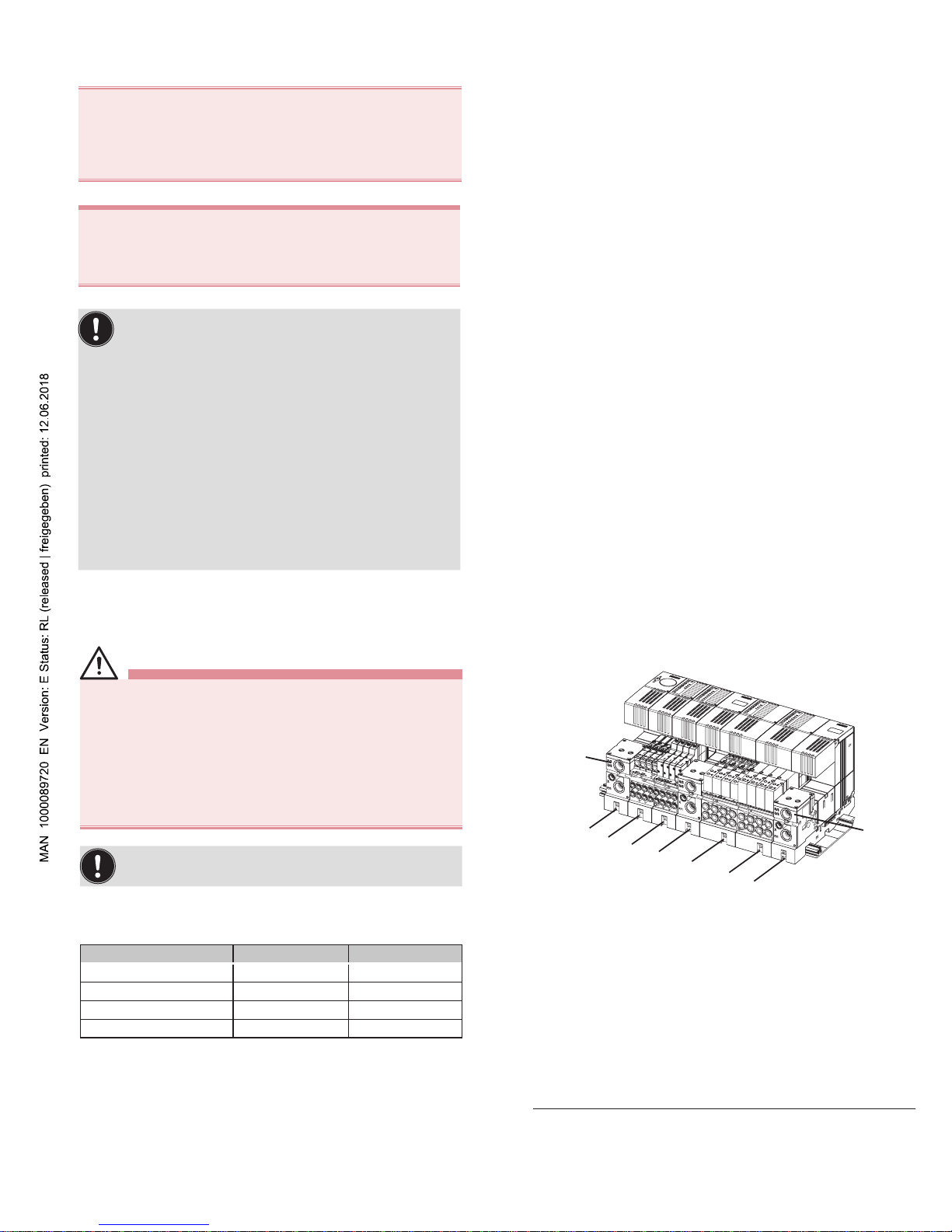
Installation example
1
2
3
8
7
6
5
4
8
Illustration: Installation example
1 Supply slice, left
2 Valve slice 44 mm, 4 Valve functions
3 Valve slice 44 mm, 8 Valve functions
1)
4 Supply slice, middle, Intermediate power supply
5 Valve slice 66 mm, 4 Valve functions
6 Valve slice 66 mm, 8 Valve functions
1)
7 Supply slice, right
8 Starting points for removal on the preassembled sys-
tem
1)
not yet available
12
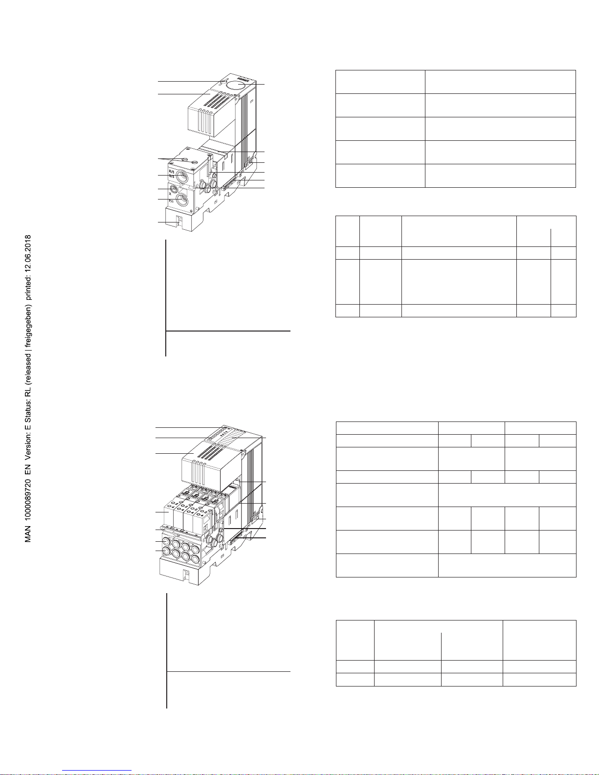
Supply slice
Illustration: Supply
slice
9
10
11
15
14
13
12
16
19
20
19
18
17
9 Storage compartement 15 Unlocking slide
2)
for SD card
16 Pressure gauge
10 Hinged cover ap
(optional)
11 Clamping bolts (2x) 17 Shut-o slide
18 Power-Bus plug
Pneumatic connections:
19 Inclined tie rods
2)
(2x)
12 R/S-3/5
20 Communication bus plug
13 X
2)
Not tted with left-hand
connecting slices
14 P/1
13
Technical data
Power consumption
0 W (Module is electrically passive)
Pneumatic
connections
G 3/8“, G 1/8“
or NPT 3/8“, NPT 1/8“
Dimensions Appr. 50 (per station 44)
x 190 x 120 mm
Material (housing
pneumatic)
PA, PBT, PC
Weight 480 g / 520 g
(without / with manometer)
Pneumatic connections
Pos. Marking Function Version
G NPT
12 R/S-3/5 Exhaust air 3/8“ 3/8“
13 X Control
EXT: Auxiliary control
air
INT: Pilot exhaust air
1/8“
14 P/1 Compressed air supply 3/8“ 3/8“
14
Valve slice
Illustration:
Valve slice
21
27
26
25
19
23
22
10
17
18
19
20
24
21 Module status (red LED) 27 Labelling panel, slot-in
22 Channel status 24 Valve ejector
1)
(green LED)
17 Shut-o slide
2)
10 Hinged cover ap 18 Power-Bus plug
23 Valves 20 Communication bus plug
19 Inclined tie rods (2x)
Pneumatic working ports:
1)
only with stacking size 66 mm
2)
under the valves
25 see table
26 see table
15
Technical data
Valve width 11 mm 16.5 mm
Valve outlets 4 8 4 8
Dimensions 44 x 120 x 135 mm66 x 120 x 135
mm
Weight with valves 580 g 690 g 1080 g n/a
Material PBT, PC (Housing)
PA (Pneumatic module)
Current consumption
[mA]
250 310 250 310
Max. power loss of
the module
2.9 W 3.6 W 2.9 W 3.6 W
Status displays Module status
1)
: LED red
Channel status: LED green
1)
Function as for Siemens modules
Pneumatic connections
Possible conguration of the working ports
Pos. Valves Double valves
3/2-way
6524/6526
5/2-way
6525/6527
2x 3/2-way
6524/6526
25 not used 2 2 (valve 12)
26 2 4 4 (valve 14)
 Loading...