

Page 1

Type 8098
FLOWave
SAW Flowmeter
Operating Instructions
Software version A.02.00.00 and higher
Page 2

We reserve the right to make technical changes without notice.
© Bürker t SAS, 2015 - 2018
Operating Instructions 1809/03 _EU-EN 00567647 / Original EN
Page 3
Type 8098
General contents
General information ..........................................................................................................................................................................5
Description.................................................................................................................................................................................................11
technical Data ........................................................................................................................................................................................19
installation in the pipe ..................................................................................................................................................................33
electrical installation .................................................................................................................................................................45
DoinG the settinGs ..............................................................................................................................................................................67
menu DISPLAY .............................................................................................................................................................................................85
menu GENERAL SETTINGS .................................................................................................................................................................93
menu SAW SENSOR - PARAMETER ............................................................................................................................................131
menu SAW SENSOR - DIAGNOSTICS ........................................................................................................................................193
menu SAW SENSOR - MAINTENANCE .......................................................................................................................................199
menu OUTPUTS .......................................................................................................................................................................................219
menu INDUSTRIAL COMMUNICATION ......................................................................................................................................237
troubleshootinG, maintenance, transport, storaGe .............................................................................. 249
English
3
Page 4

Type 8098
General contents
4
English
Page 5
Type 8098
General information
1 ABOUT THESE OPERATING INSTRUCTIONS ....................................................................................................................6
1.1 Symbols used .........................................................................................................................................................................6
1.2 Definition of the word device ..........................................................................................................................................6
1.3 Definition of the word büS ................................................................................................................................................7
1.4 Validity of the Operating Instructions .........................................................................................................................7
2 INTENDED USE ....................................................................................................................................................................................7
3 BASIC SAFETY INFORMATION ....................................................................................................................................................8
4 GENERAL INFORMATION .............................................................................................................................................................10
4.1 Manufacturer's address and international contacts .........................................................................................10
4.2 Warranty conditions ...........................................................................................................................................................10
4.3 Information on the Internet ............................................................................................................................................10
English
5
Page 6
Type 8098
About these Operating Instructions
1 ABOUT THESE OPERATING INSTRUCTIONS
The Operating Instructions describe the entire life cycle of the device. Please keep the Operating Instructions in a
safe place, accessible to all users and any new owners.
The Operating Instructions contain important safety information.
Failure to comply with these instructions can lead to hazardous situations. Pay attention in particular to the
chapters 3 Basic safety information and 2 Intended use.
▶ Irrespective of the device version, the Operating Instructions must be read and understood.
1.1 Symbols used
DanGer
Warns against an imminent danger.
▶ Failure to observe this warning results in death or in serious injury.
WarninG
Warns against a potentially dangerous situation.
▶ Failure to observe this warning can result in serious injury or even death.
caution
Warns against a possible risk.
▶ Failure to observe this warning can result in substantial or minor injuries.
notice
Warns against material damage.
Indicates additional information, advice or important recommendations.
Refers to information contained in these Operating Instructions or in other documents.
▶ Indicates an instruction to be carried out to avoid a danger, a warning or a possible risk.
→ Indicates a procedure to be carried out.
A highlighted term is related to a menu or a menu item.
Indicates the result of a specific instruction.
1.2 Definition of the term device
The term "device" used in these Operating Instructions always refers to the Type 8098 flowmeter.
6
English
Page 7
Type 8098
About these Operating Instructions
1.3 Definition of the term büS
The term "büS" used in these Operating Instructions refers to the industrial communication, developed by Bürkert,
based on the CANopen protocol.
→ For more information on büS, read the cabling guide available in English and German (Cabling_guide_for_
büS_networks.pdf) at www.buerkert.com search for "Guide for planning büS networks".
→ For more information on CANopen which is related to the device, refer to the Operating Instructions
"CANopen Network configuration" at www.buerkert.com.
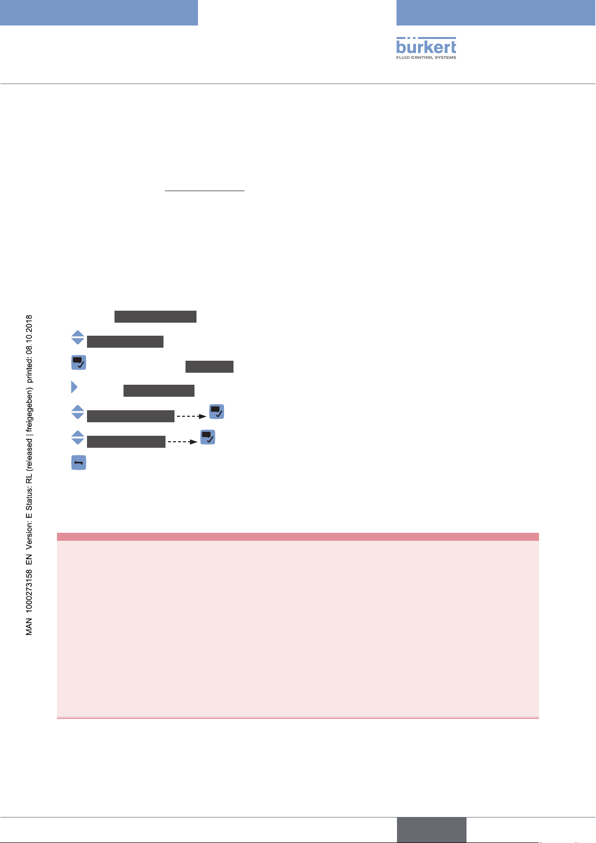
1.4 Validity of the Operating Instructions
The Operating Instructions are valid for the devices from software version A02.00.00.
To read out the version number of the device software, do the following:
→ Go to the CONFIGURATION view.
→ General settings
→ Confirm to access the Parameter view.
→ Go to the MAINTENANCE view.
→ Device information
→ Software version
→ Go back to the parent menu.
2 INTENDED USE
Use of the device that does not comply with the instructions could present risks to people, nearby
installations and the environment.
The Type 8098 flowmeter is intended to measure the flow rate of clean liquids, non emulsified (homogeneous liquids) and free of air bubbles and free of gas bubbles and free of solids, using the Surface
Acoustic Wave (SAW) measurement principle.
▶ Use the device in compliance with the characteristics and the conditions of commissioning and use specified
in the contractual documents and in the Operating Instructions.
▶ Protect the device against electromagnetic interference, ultraviolet rays and, when installed outdoors, against
the effects of climatic conditions.
▶ Only operate a device in perfect working order.
▶ Properly transport, store, install and operate the device.
▶ Only use the device as intended.
7
English
Page 8
Type 8098
Basic safety information
3 BASIC SAFETY INFORMATION
This safety information does not take into account any contingencies or occurrences that may arise during installation, use and maintenance of the product.
The operating company is responsible for the respect of the local safety regulations, including staff safety.
Risk of injury due to electrical voltage.
▶ Before carrying out work on the system, disconnect the electrical power for all the conductors and isolate it.
▶ Observe all applicable accident protection and safety regulations for electrical equipment.
Risk of injury due to high pressure in the installation.
▶ Before any intervention in the installation, stop the circulation of fluid, cut off the pressure and drain the pipe.
▶ Before any intervention in the installation, make sure there is no pressure in the pipe.
▶ Observe the dependency between the fluid temperature and the fluid pressure for the fitting used.
If switched on for a prolonged time, risk of burns or fire due to hot device surfaces
▶ Do not touch with bare hands.
▶ Keep the device away from highly flammable substances and fluids.
Risk of burns due to high fluid temperatures.
▶ Do not touch with bare hands the parts of the device that are in contact with the fluid.
▶ Use safety gloves to handle the device.
▶ Before opening the pipe, stop the circulation of fluid and drain the pipe.
▶ Before opening the pipe, make sure the pipe is completely empty.
Risk of injury due to the nature of the fluid.
▶ Respect the prevailing regulations on accident prevention and safety relating to the use of dangerous fluids.
General dangerous situations
To avoid injury:
▶ Do not use the device in explosive atmospheres.
▶ Do not use the device in an environment incompatible with the materials it is made of.
▶ Do not use fluid that is incompatible with the materials the device is made of.
▶ Do not subject the device to mechanical loads.
▶ Do not make any modifications to the device.
▶ Prevent any unintentional power supply switch-on.
▶ Only qualified and skilled staff may carry out installation and maintenance work.
▶ Ensure a defined or controlled restarting of the process after a power supply interruption.
▶ Observe the general technical rules.
8
English
Page 9
Type 8098
Basic safety information
caution
Risk of injury due to a heavy device.
A heavy device can fall down during transport or during installation and cause injuries.
▶ Transport, install and dismantle a heavy device with the help of another person.
▶ Use appropriate tools.
notice
The device may be damaged by the measured fluid.
▶ Systematically check the chemical compatibility of the component materials of the device and the fluids likely
to come into contact with the materials (for example: alcohols, strong or concentrated acids, aldehydes, alkaline compounds, esters, aliphatic compounds, ketones, halogenated aromatics or hydrocarbons, oxidants and
chlorinated agents).
notice
Elements/components sensitive to electrostatic discharges
▶ This device contains electronic components that are sensitive to electrostatic discharges. They may be dam-
aged if they are touched by an electrostatically charged person or object. In the worst case scenario, these
components are instantly destroyed or disabled as soon as they are activated.
▶ To minimise or even avoid any damage caused by an electrostatic discharge, take all the precautions
described in standard EN 61340-5-1.
▶ Also make sure that you do not touch any of the live electrical components.
English
9
Page 10
Type 8098
General information
4 GENERAL INFORMATION
4.1 Manufacturer's address and international contacts
To contact the manufacturer of the device, use the following address:
Bürkert SAS
Rue du Giessen
BP 21
F-67220 TRIEMBACH-AU-VAL
You may also contact your local Bürkert sales office.
The addresses of our international sales offices are available on the internet at:
www.burkert.com
4.2 Warranty conditions
The condition governing the legal warranty is the conforming use of the device in observance of the operating
conditions specified in the Operating Instructions.
4.3 Information on the Internet
You can find the operating instructions and the technical data sheets for Type 8098 at:
www.burkert.com
10
English
Page 11

Type 8098
Description
5 DESCRIPTION ....................................................................................................................................................................................12
5.1 Knowing the device ...........................................................................................................................................................12
5.1.1 Wi-Fi module .......................................................................................................................................13
5.1.2 Unlocking magnetic key ....................................................................................................................14
5.2 Understanding the rating plates .................................................................................................................................14
5.3 Marking with the MAC address ...................................................................................................................................16
5.4 Description of the device status LED .....................................................................................................................17
English
11
Page 12
Type 8098
Description
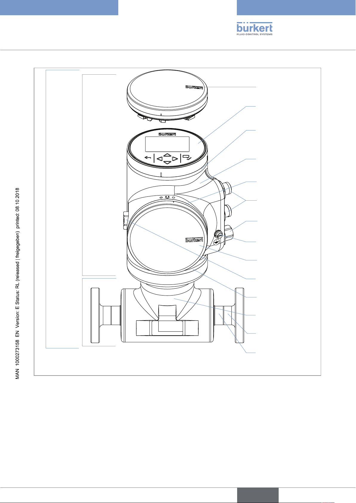
5 DESCRIPTION
5.1 Knowing the device
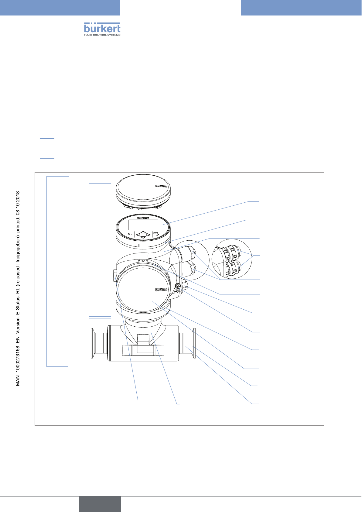
The Type 8098 flowmeter is made up of a Type SE98 transmitter and a Type S097 flow sensor.
The following pictures describe the main versions of the Type 8098 flowmeter:
• Fig. 1 describes a device with 2 M20x1,5 cable glands in stainless steel (or in nickel plated brass) and 1 5-pin
M12 male connector.
• Fig. 2 describes the Ethernet version of the device, i.e. a device with 2 4-pin M12 female connectors and 1
5-pin M12 male connector.
Blind cover
Type SE98
transmitter
Type 8098 flowmeter
Type S097 flow
sensor
or display module (Type ME31)
Device status LED indicating the
status of the device, and seal
Transmitter housing, including
the electronic modules
Cable glands in nickel plated
brass, with blind plugs
or cable glands in stainless steel,
with blind plugs
Seal
5-pin M12 male connector, with
screwed plug
Functional earth
Seal
Blind cover
12
Process connection
Pressure compensating element
1) The process connections can be either clamp connections or flange connections.
Sensor housing
Sensor measurement tube
Fig. 1: Description of the device with 2 M20x1,5 cable glands and 1 5-pin M12 male connector
English
1)
Page 13
Type SE98
transmitter
Type 8098
Description
Blind cover
or display module (Type ME31)
Device status LED indicating the
status of the device, and seal
Transmitter housing, including
the electronic modules
Seal
Type 8098 flowmeter
Type S097 flow
sensor
1) The process connections can be either clamp connections or flange connections.
4-pin M12 female connectors
with plugs
5-pin M12 male connector, with
screwed plug
Functional earth
Blind cover
Pressure compensating element
Seal
Sensor housing
Process connection
Sensor measurement tube
1)
Fig. 2: Description of an Ethernet version of the device, with 2 4-pin M12 female connectors and 1 5-pin M12 male
connector
5.1.1 Wi-Fi module
The device can be equipped with a Wi-Fi module in place of or in addition to the display module. The Wi-Fi
module has the Type number ME31, too. The Wi-Fi module has the same functional scope as the display module.
The Wi-Fi module is intended for use in Europe, the USA, and Canada.
The module can be integrated into an existing WLAN infrastructure. The wireless range is approximately 10 m.
English
13
Page 14
Type 8098
21
911
13
10
3
12
Description
The module provides a web server which can be accessed if the following requirements are met:
• Windows 7/8.1/10: IE11, Edge, Google Chrome, from version 53.
• Android with Google: Chrome, from version 53.
• Apple: Safari, from iOS 9.3.5.
5.1.2 Unlocking magnetic key
The device is delivered with a magnetic key to unlock the display module or the blind cover. See Fig. 3.
Fig. 3: Unlocking magnetic key
The device operates on a 4-wire system and needs a 12...35 V DC power supply.
The device has three outputs:
• 1 analogue output,
• 1 digital output,
• 1 output, which can be configured as an analogue output or as a digital output.
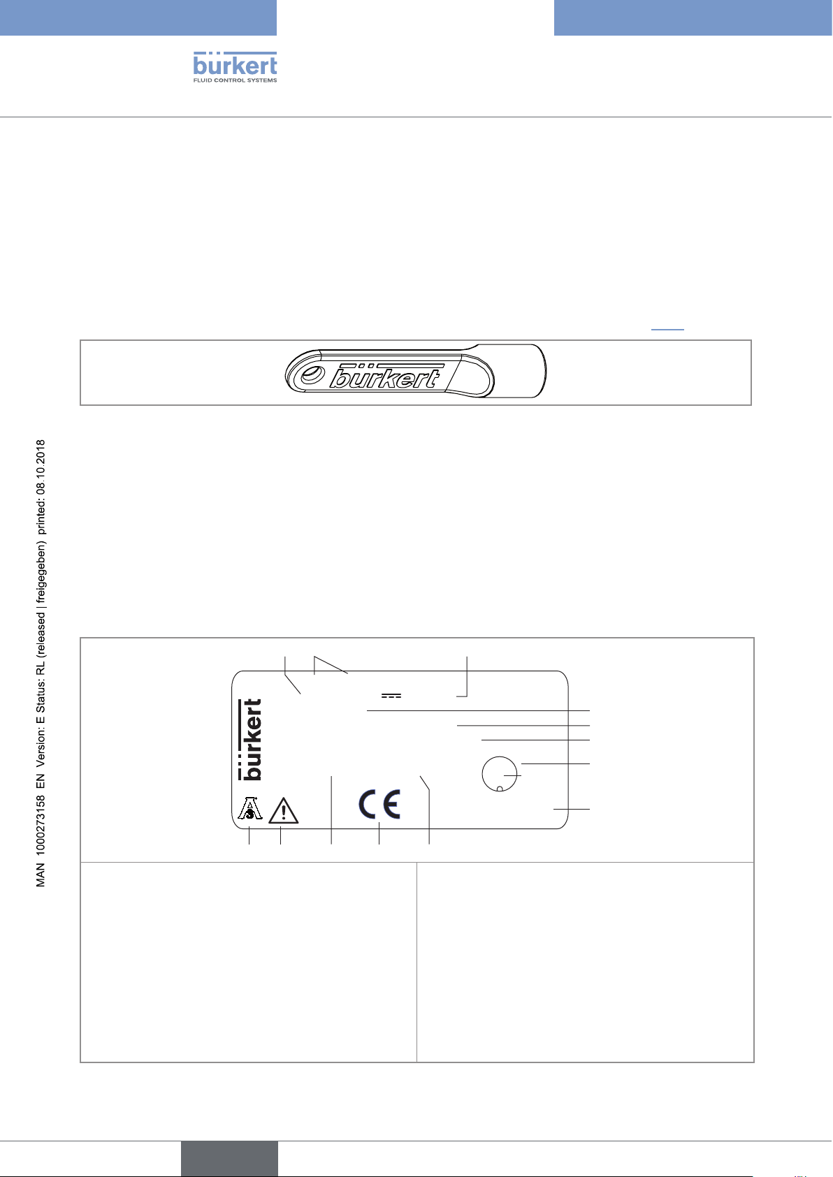
5.2 Understanding the rating plates
8098 FLOWave Flowmeter
Supply: 12-35 5W Max.
IP65 / IP67
Temp. ambient: -10 to 70°C
NEMA 4X Not evaluated by UL
88888888 SN 999999
F-67220 Triembach
W49MN
28-04
1. Supply voltage
CAN_H GND
34
5 CAN_L
21
CAN shield
Made in France
V+
8. Construction code
4
5
6
7
8
14
2. Type of the device
3. Power consumption
4. IP Protection class of the device
5. Ambient temperature range
6. Protection class of the device
7. Pin assignment of the 5-pin M12 male connector
Fig. 4: Rating plate of the Type 8098 flowmeter (example of a UL device)
English
9. Serial number
10. Conformity marking
11. Article number
12. Warning: Before using the device, take into account
the technical specifications given in the Operating
Instructions.
13. Certification
Page 15
Type 8098
21
68
10
7
9
1
7
Description
28-04
8098 FLOWave Flowmeter
IP65 / IP67 / NEMA 4X
Temp. ambient: -10 to 55°C
88888888 SN 999999
CAN_H GND
34
5 CAN_L
F-67220 Triembach
W49MN
CAN shield
Made in France
21
V+
3
4
5
1. Protection class of the device
2. Type of the device
3. Ambient temperature range
7. Conformity marking
8. Article number
9. Warning: Before using the device, take into account
the technical specifications given in the Operating
4. Pin assignment of the 5-pin M12 male connector
5. Construction code
Instructions.
10. Certification
6. Serial number
Fig. 5: Rating plate of the Type 8098 flowmeter (example of a non-UL Ethernet device)
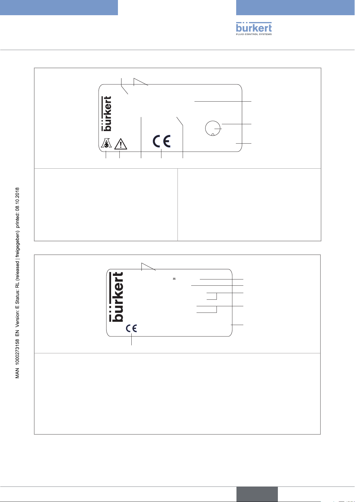
SE98 FLOWave Transmitter
Supply: 12-35V 5W max
Housing: 304 / 1.4301
Slot 5: Indust. communication
Slot 4: 1AO-1DO-1AO/DO
ME31 - Display module
ME31 - WIFI module
F-67220 Triembach
W49MN
Made in France
2
3
4
5
6
1. Type of the transmitter
2. Power supply and maximum power consumption
3. Housing material
4. Communication type and available outputs
5. Communication modules
6. Construction code
7. Conformity marking
Fig. 6: Rating plate of the Type SE98 transmitter (example of an Ethernet device with display module and Wi-Fi
module)
English
15
Page 16
Type 8098
1
7
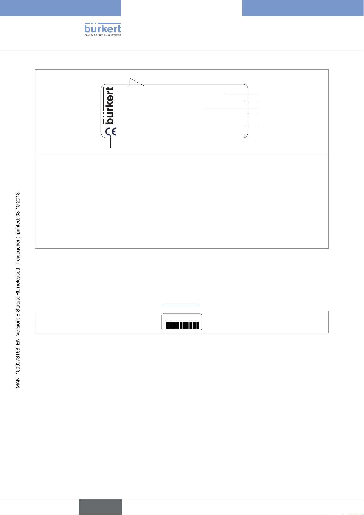
Description
S097 FLOWave Flow sensor
Pipe: 316L/1.4435 Housing: 304/1.4301
DIN 11866 C / Clamp D50.5 DIN 32676 B DN15
PN25bar Max. flow:10 m3/h
Temp. medium : -20 to 110°C
F-67220 Triembach
W4ZMN
Made in France
2
3
4
5
6
1. Type of the flow sensor
2. Material of the pipe and material of the housing
3. Standard the pipe conforms to; type of process connection, external diameter of the clamp and standard the
process connection conforms to; DN of the measurement tube
4. Pressure class of the device and maximum flow rate
5. Fluid temperature range
6. Construction code
7. Conformity marking
Fig. 7: Rating plate of the Type S097 flow sensor (example)
5.3 Marking with the MAC address
The marking with the MAC address can be seen by opening the front of the transmitter.
→ To open the front of the transmitter, see chpt. 8.10, page 53.
DC-B0-58-FF-FF-FF
Fig. 8: Marking with the MAC address of the device (example)
16
English
Page 17
Type 8098
Description
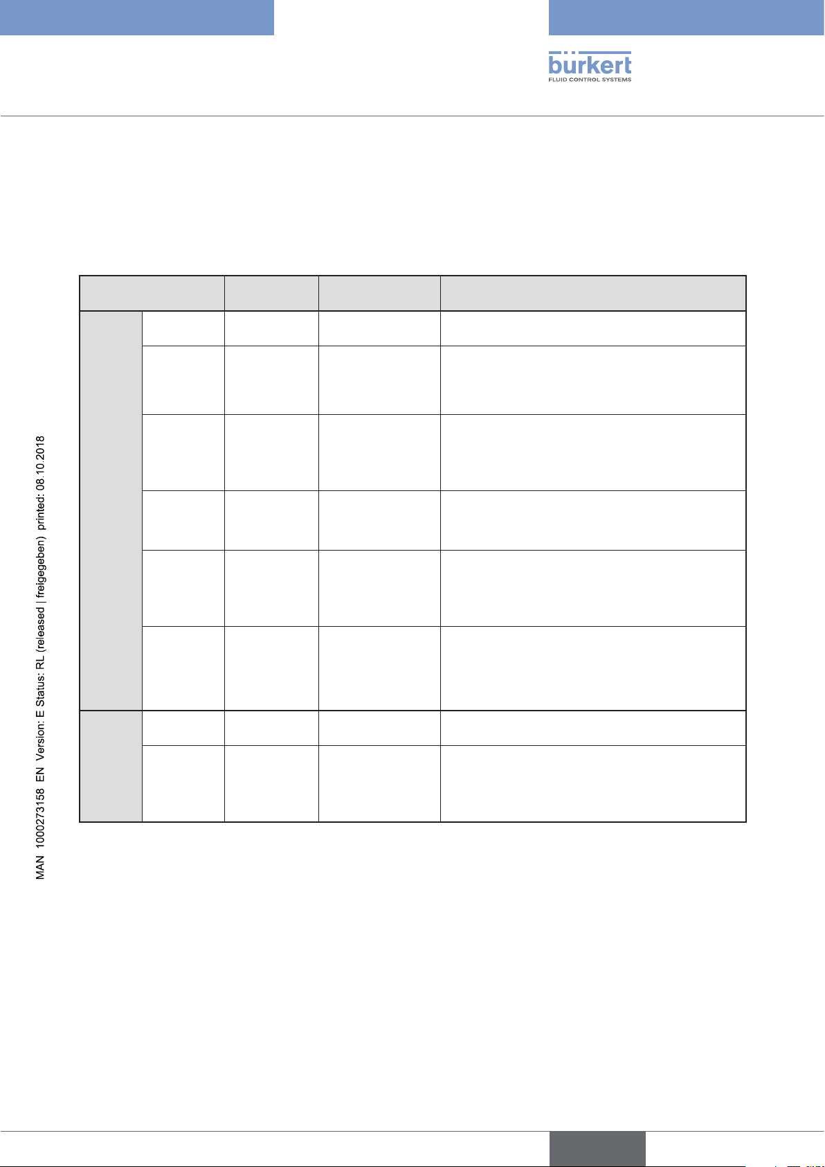
5.4 Description of the device status LED
Ex works, the LED that indicates the state of the device changes its colour and state based on the NAMUR
NE 107 recommendation.
If several states exist simultaneously, the state with the highest priority is displayed. The priority is determined by
the severity of the deviation from standard operation (red LED = failure, error or malfunction = highest priority).
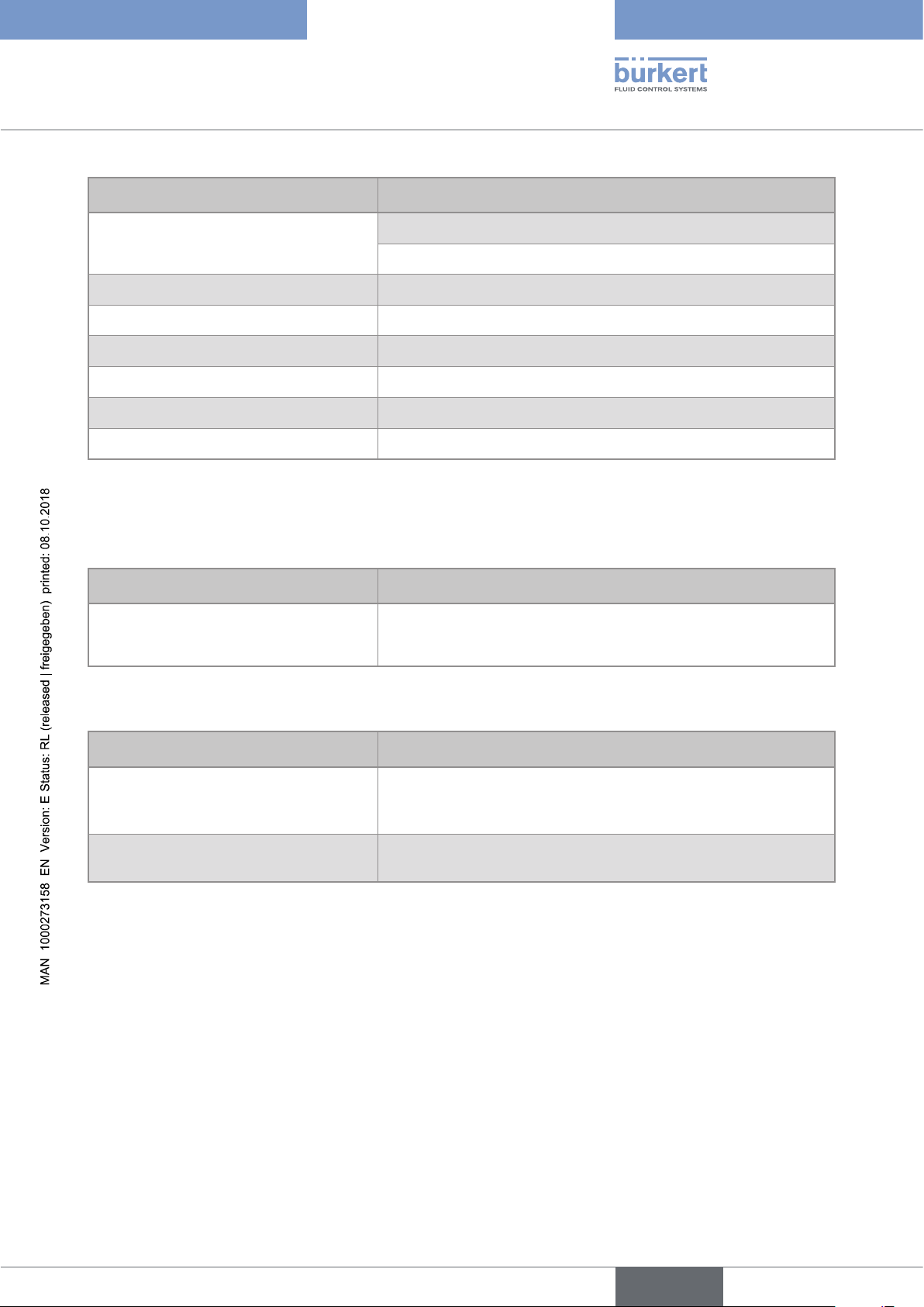
Device status LED Colour code
(for a PLC)
Colour
State
Red 5 Failure, error,
Orange 4 Function check Ongoing work on the device (for example,
Yellow 3 Out of
Blue 2 Maintenance
Green 1 Diagnostics active No event has been generated. Status changes are
White 0 Diagnostics
ON - Device is in oper-
Flashing
rapidly
- Identification Serves as identification of a device in the
Description Meaning
Due to a malfunction of the device or its periphery,
malfunction
specification
required
the measured values can be incorrect.
checking the correct behaviour of the outputs by
simulating measurement values); the output signal
is temporarily invalid (e.g. frozen).
The ambient conditions or process conditions for
the device are outside the permitted ranges.
Device internal diagnostics point to problems in
the device or with the process properties.
The device continues to measure but a function is
temporarily restricted.
→ Do the required maintenance operation.
shown in colour.
Messages are listed and possibly transmitted via
any connected fieldbus.
Device is switched on.
inactive
ating state.
Status changes are not shown.
Messages are neither listed nor transmitted via any
connected fieldbus.
Device is in standard operation.
büS network.
The device was selected using the Bürkert Communicator software.
Table 1: Device status LED - colours and states in accordance with NAMUR NE 107, edition 2006-06-12
English
17
Page 18
Type 8098
18
English
Page 19

Type 8098
Technical data
6 TECHNICAL DATA .............................................................................................................................................................................20
6.1 Operating conditions ........................................................................................................................................................20
6.2 Conformity to standards and directives .................................................................................................................20
6.3 Conformity to the Pressure Equipment Directive ..............................................................................................20
6.4 UL certification .....................................................................................................................................................................21
6.5 EHEDG certification ...........................................................................................................................................................21
6.6 Fluid data .................................................................................................................................................................................22
6.7 Measurement data .............................................................................................................................................................24
6.8 Electrical data .......................................................................................................................................................................25
6.9 Mechanical data ...................................................................................................................................................................26
6.10 Specifications of the Ethernet Industrial communication ............................................................................28
6.10.1 Modbus TCP protocol .......................................................................................................................28
6.10.2 PROFINET protocol ...........................................................................................................................28
6.10.3 EtherNet/IP protocol ..........................................................................................................................29
6.10.4 EtherCAT protocol .............................................................................................................................31
English
19
Page 20
6 TECHNICAL DATA
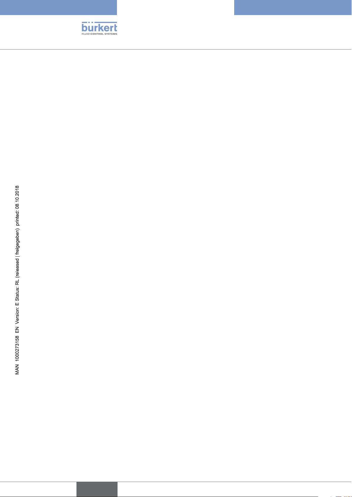
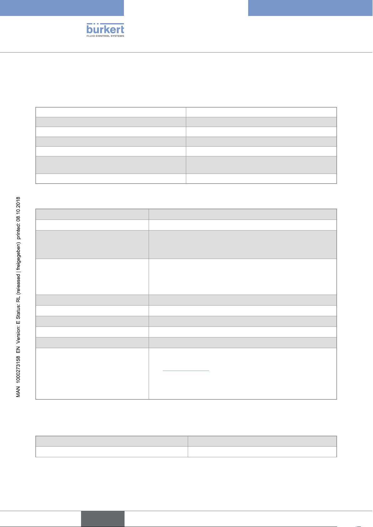
6.1 Operating conditions
Ambient temperature
• Device with 2 M20x1,5 cable
glands and 1 5-pin M12
connector
• Device with 2 4-pin M12 female
connectors and 1 5-pin M12 con-
nector (Ethernet version)
Air humidity < 85%, non condensing
Height above see level max. 2000 m
Installation category Category I according to UL 61010-1
Degree of pollution Degree 2 according to EN 61010-1
Protection class according to
EN 60529
Protection class according to
NEMA250
(not evaluated by UL)
• –10...+70 °C
• –10...+55 °C
IP65, IP67, if the device is wired and if the cable glands are tightened and
the covers are screwed tight. Unused cable glands must be sealed with
the stopper gaskets provided (mounted upon delivery of the device). An
unused M12 connector must be protected by the screwed plug.
4X, if the device is wired and if the cable glands are tightened and the
covers are screwed tight. Unused cable glands must be sealed with the
stopper gaskets provided (mounted at the delivery of the device). An
unused M12 connector must be protected by the screwed plug.
Type 8098
Technical data
6.2 Conformity to standards and directives
The applied standards, which verify conformity with the EU Directives, can be found on the EU Type Examination
Certificate and/or the EU Declaration of Conformity (if applicable).
6.3 Conformity to the Pressure Equipment Directive
→ Make sure the device materials are compatible with the fluid.
→ Make sure the pipe DN is adapted for the device.
The device conforms to Article 4, Paragraph 1 of the Pressure Equipment Directive 2014/68/EU under the following conditions:
• Device used on a pipe (PS = maximum admissible pressure; DN = nominal diameter of the pipe)
Type of fluid Conditions
Fluid group 1, Article 4, Paragraph 1.c.i DN≤25
Fluid group 2,Article 4, Paragraph 1.c.i
Fluid group 1, Article 4, Paragraph 1.c.ii
DN≤32
or PSxDN≤1000
DN≤25
or PSxDN≤2000
20
English
Page 21
Type 8098
Measuring
Equipment
EXXXXXX
®
Technical data
Type of fluid Conditions
DN≤200
Fluid group 2, Article 4, Paragraph 1.c.ii
or PS≤10
or PSxDN≤5000
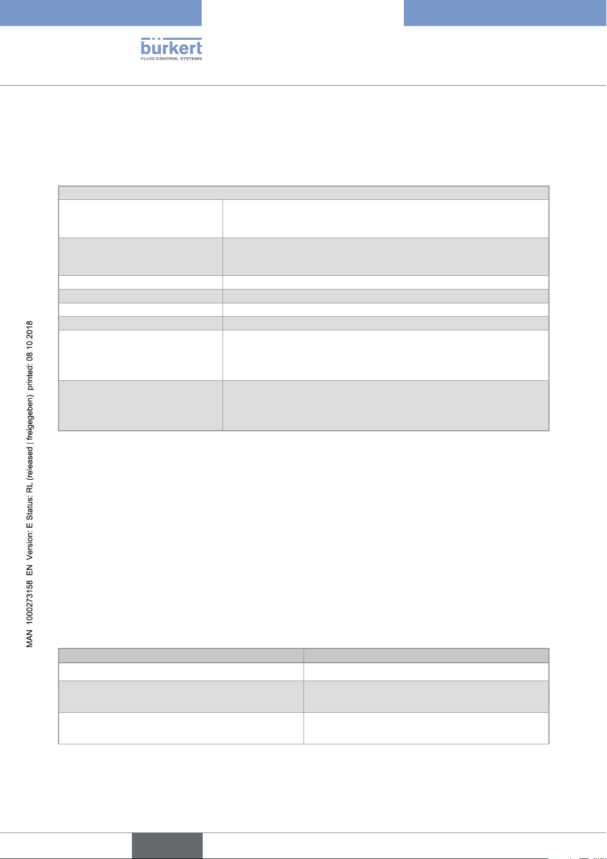
6.4 UL certification
The devices with variable key PU01 or PU02 are UL-certified devices and comply also with the following standards:
• UL 61010-1
• CAN/CSA-C22.2 n°61010-1
Identification on the device Certification Variable key
UL recognized PU01
UL listed PU02
6.5 EHEDG certification
• EL class I
• The following versions are EHEDG certified:
Process connections Diameters
• Clamp
connections according to ASME BPE
• 3/4'', 1'', 1 1/2'', 2''
1)
(DIN 32676 series C)
• Clamp connections according to DIN 11864-3
• 3/4'', 1'', 1 1/2'', 2''
series C
• Flange connections according to DIN 11864-2
• 3/4'', 1'', 1 1/2'', 2''
series C
1)
• Clamp
connections according to
DIN 32676 series B
1)
• Clamp
connections according to
• DN15 (except variants with a clamp diameter of
34.0 mm) DN25, DN40, DN50
• DN15, DN25, DN40, DN50
DIN 32676 series A
• Clamp connections according to DIN 11864-3
• DN15, DN25, DN40, DN50
series A, DIN 11864-3 series B
• Clamp
connections according to SMS 3017 /
• DN25, DN40, DN50
1)
ISO 2852 for pipes according to SMS 3008
• Flange connections according to DIN 11864-2
• DN15, DN25, DN40, DN50
series A, DIN 11864-2 series B
1)
The EHEDG compliance is only valid if used in combination with EHEDG-compliant gaskets from Combifit
International B.V.
The manufacturer of the device does not supply any gaskets for the process connections.
→ To make sure you use EHEDG-compliant gaskets, refer to the "EHEDG Position Paper" available on the
EHEDG website.
21
English
Page 22
6.6 Fluid data
80 140
°C
°C
0204060 100 120-20
-1
80 140
°C
°C
0204060 100 120-20
-1
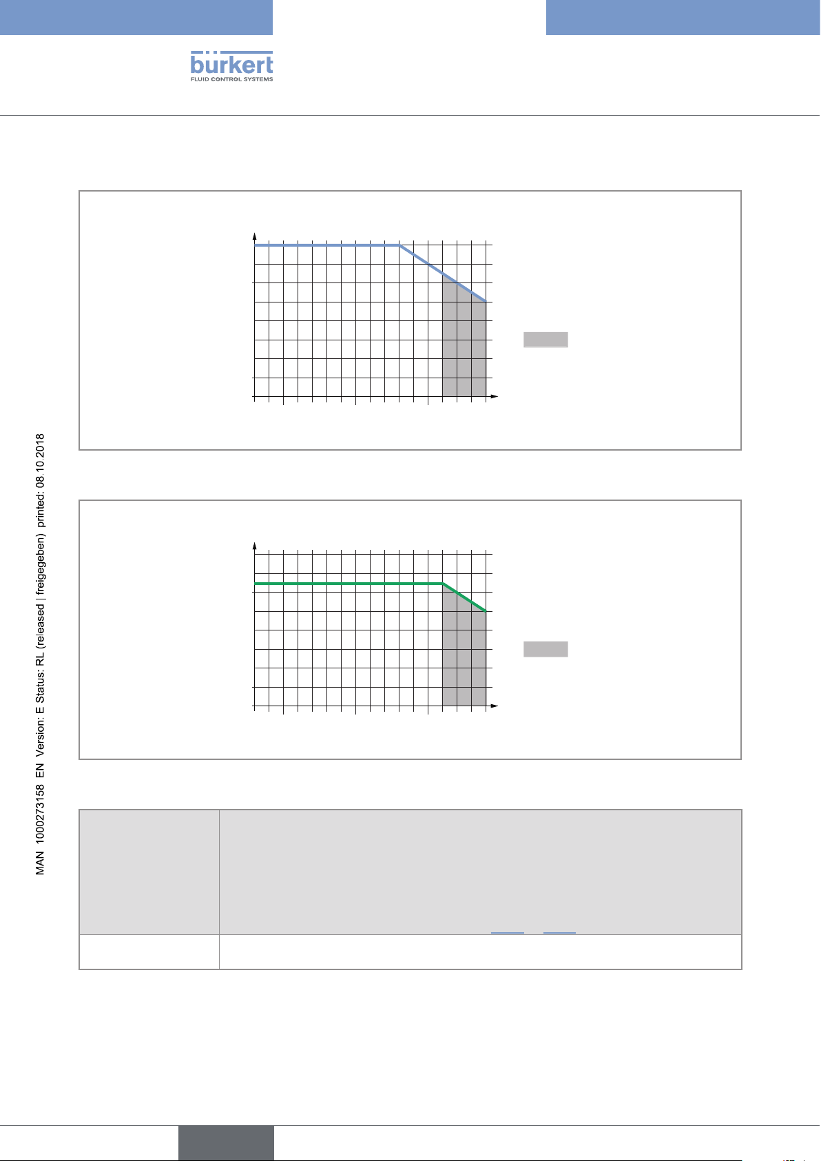
Ambient temperature
70
60
40
Type 8098
Technical data
20
Temperatures authorized
for a limited duration
0
0
Fluid temperature
Fig. 8: Dependency between the fluid temperature and the ambient temperature, device with 2 M20x1,5 cable glands
and 1 5-pin M12 male connector
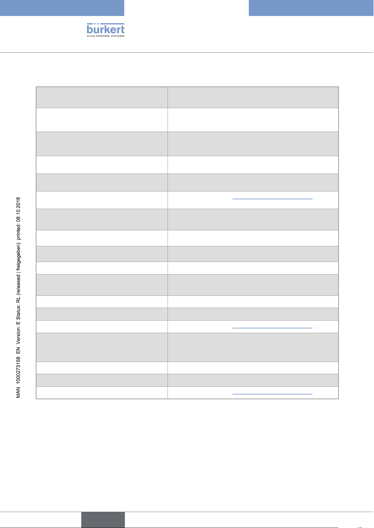
Ambient temperature
70
55
40
20
Temperatures authorized
for a limited duration
0
0
Fluid temperature
Fig. 9: Dependency between the fluid temperature and the ambient temperature, device with 2 4-pin M12 female
connectors and 1 5-pin M12 male connector (Ethernet version)
Fluid temperature –20...+110 °C, with clamp process connections. Up to 140 °C for maximum
60 minutes for a sterilisation process.
Maximum temperature gradient: 10 °C/s [measured by the sensor integrated in the
device]
The maximum fluid temperature can be restricted by the ambient operating temperature.
Depending on the version of your device, see Fig. 8 or Fig. 9
Type of fluids Non-dangerous liquids according to Article 4, Paragraph 1 of Directive 2014/68/EU
22
English
Page 23

Type 8098
Technical data
Size of the process
connection
Type of process connection
clamp
DN15, DN25
flange
DN25 clamp
clamp
3/4'', 1'', 1 1/2''
flange DIN 11864-2 series C PN25
clamp
DN40
Standards the process connections
conform to
• DIN 11864-3 series A
• DIN 11864-3 series B
• DIN 32676 series A
• DIN 32676 series B
• DIN 11864-2 series A
• DIN 11864-2 series B
SMS 3017 / ISO 2852 for pipes
according to SMS 3008
• ASME BPE (DIN 32676 series C)
• DIN 11864-3 series C
• DIN 11864-3 series B
• DIN 32676 series B
• DIN 11864-3 series A
• DIN 32676 series A
• SMS 3017 / ISO 2852 for pipes
according to SMS 3008
PN
PN25
PN25
PN25
PN25
PN16
PN25
DIN 11864-2 series B PN16
flange
DIN 11864-2 series A PN25
• DIN 11864-3 series A
• DIN 11864-3 series B
DN50
clamp
• DIN 32676 series A
• DIN 32676 series B
PN16
• SMS 3017 / ISO 2852 for pipes
according to SMS 3008
• DIN 11864-2 series A
flange
PN16
• DIN 11864-2 series B
• ASME BPE (DIN 32676 series C)
2''
clamp
• DIN 11864-3 series C
PN16
flange DIN 11864-2 series C PN16
Table 2: Fluid pressure, depending on the pipe diameter, the type of process connections and the process connection
standard
English
23
Page 24
6.7 Measurement data
Flow rate measurement
Type 8098
Technical data
• Measurement range • 0...7 m
1) 2)
• Measurement deviation
for a flow rate
• ±0.4% of the measured value
3
/h to 0...90 m3/h, depending on the DN of the sensor
between 10% of the full scale and the full
scale
• Measurement deviation
for a flow rate
• < ±0.08% of the full scale
1) 2)
between 1% of the full scale and 10% of the
full scale
• Repeatability
2)
for a flow rate between 10% of
• ±0.2% of the measured value
the full scale and the full scale
• Repeatability
for a flow rate between 1% of
• ±0.04% of the full scale
2)
the full scale and 10% of the full scale
• Refresh time
• Adjustable, see chpt. 14.11 Setting the refresh time.
Temperature measurement
• Measurement range • –20...+140 °C
• Measurement deviation
for temperatures up
• ±1 °C
1)
to 100 °C
• Measurement deviation
for temperatures
• ±1.5%
1)
between 100 °C and 140 °C
• Refresh time • 1 s
Density factor measurement (optional feature)
• Measurement range • 0,8...1,3
• Resolution • 0,00001
• Repeatability • ±0.5% of the measured value
• Refresh time
• Adjustable, see chpt. 14.11 Setting the refresh time.
Acoustic transmission factor measurement
(optional feature)
• 10...120%
• Measurement range
• Resolution • 0,01%
• Repeatability • ±2% of the measured value
• Refresh time
1) "Measurement bias" as defined in standard JCGM 200:2012.
2) Determined under the following reference conditions: fluid = water, free of gas bubbles and solids; water and ambient
temperatures = 23 °C, refresh time of 190 ms, applying the minimum inlet (40xDN) and minimum outlet (1xDN) straight pipe
lengths, appropriate pipe dimensions.
• Adjustable, see chpt. 14.11 Setting the refresh time.
24
English
Page 25
Type 8098
Technical data
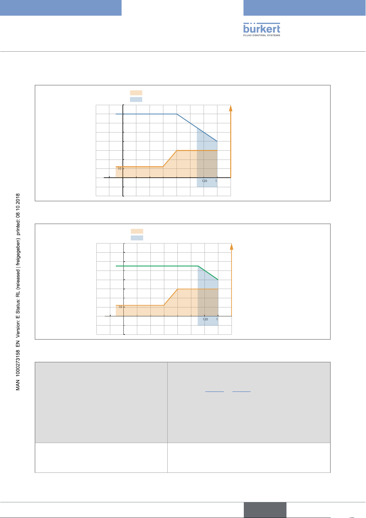
6.8 Electrical data
Ambient temperature °C
80
70
60
50
40
30
20
10
0
-20 0 20 40 60 80 100 120 140 160
-10
-20
Voltage not allowed
Temperature authorized for a limited duration
Supply voltage V DC
35
30
25
20
15
10
5
Fluid temperature °C
Fig. 10: Minimum supply voltage depending on the ambient temperature and the fluid temperature, device with 2
M20x1,5 cable glands and 1 5-pin M12 male connector
Voltage not allowed
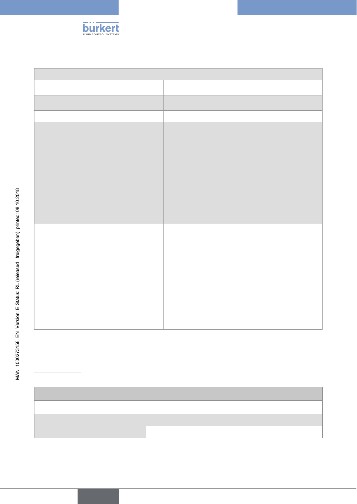
Ambient temperature °C
80
70
60
50
40
30
20
10
0
-20 0 20 40 60 80 100 120 140 160
-10
-20
Temperature authorized for a limited duration
Supply voltage V DC
35
30
25
20
15
10
5
Fluid temperature °C
Fig. 11: Minimum supply voltage depending on the ambient temperature and the fluid temperature, device with 2 4-pin
M12 female connectors and 1 5-pin M12 male connector (Ethernet version)
Operating voltage • 12...35 V DC; the minimum voltage to be supplied
depends on the fluid temperature and on the ambient
operating temperature: depending on the version of your
device, see Fig. 10 or Fig. 11
• Current consumption: max. 2 A
• Filtered and regulated
• Tolerance: ±10%
• SELV circuit, at a non-dangerous energy level
Energy source (not supplied) Limited energy source according to paragraph 9.4 of
standard EN 61010-1
English
25
Page 26
Power consumption (without the consumption of the outputs)
Type 8098
Technical data
• Device with 2 M20x1,5 cable glands and 1
• ≤ 5 W
5-pin M12 connector
• Device with 2 4-pin M12 female connectors
• ≤ 8 W
and 1 5-pin M12 connector (Ethernet version)
Polarity reversal Protected
Analogue output 1, also output 3 if configured as
• 4...20 mA current; 3.6 mA or 22 mA to indicate an error
an analogue output
• Uncertainty: ±0.04 mA
• Resolution: 0.8 µA
• Open loop detection through diagnostics software function
• Any connection mode, in sink or source mode
• Galvanically isolated, passive
• Protected against polarity reversal
• Maximum loop impedance 1300W at 35 V DC, 1000W at
30 V DC, 700W at 24 V DC, 450W at 18 V DC
Digital output 2, also output 3 if configured as a
• Transistor
digital output
• Any connection mode, in NPN or PNP mode
• Pulse (by default), can be changed by the user
• 0...2000 Hz
• 5...35 V DC, max. 700 mA
• Galvanically isolated, passive
• Overload information through diagnostics software function
• Protected against overloads
• Protected against polarity reversals
6.9 Mechanical data
Dimensions and weight of the device: refer to the technical data sheet regarding Type 8098 available at
www.buerkert.com
Table 3: Materials in contact with ambient air
Component Material
Transmitter housing
Cable glands / Blind plugs
(depending on the version of your device)
1)
, sensor housing Stainless steel 304 / 1.4301, outer surface finish Ra < 1.6 µm
Stainless steel / PA6
Nickel plated brass / Black polyoxymethylene (POM)
26
English
Page 27
Type 8098
Technical data
Component Material
5-pin M12 male connector / Screwed plug
(depending on the version of the device)
Stainless steel / Stainless steel
Nickel plated brass / Nickel plated brass
4-pin M12 female connector / Blind plug Stainless steel / Stainless steel
Pressure compensating element Stainless steel
External M4 screw for earth connection Stainless steel A4
Display Float glass, stainless steel 304 / 1.4301
Seals VMQ silicone
Rating plate Polyester
1)
The housing may have slight machining marks due to the manufacturing process. These marks do not affect the
operation of the device and are not a manufacturing defect.
Table 4: Materials in contact with the fluid
Component Material
• Sensor measurement tube
Stainless steel 316L / DIN 1.4435 BN2
• Pipe connections
Table 5: Available surface finish
Component Surface finish according to ISO 4288
Ra < 0.8 µm
Measurement tube (inner surface)
or Ra < 0.4 µm
• Measurement tube (outer surface)
Ra < 1,6 µm (excluding welding seams)
• Housing
English
27
Page 28
Type 8098
Technical data
6.10 Specifications of the Ethernet Industrial communication
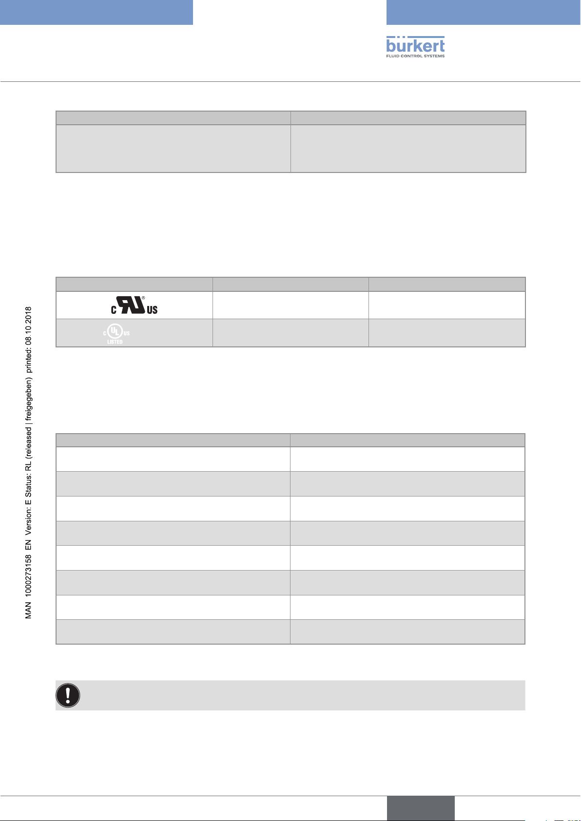
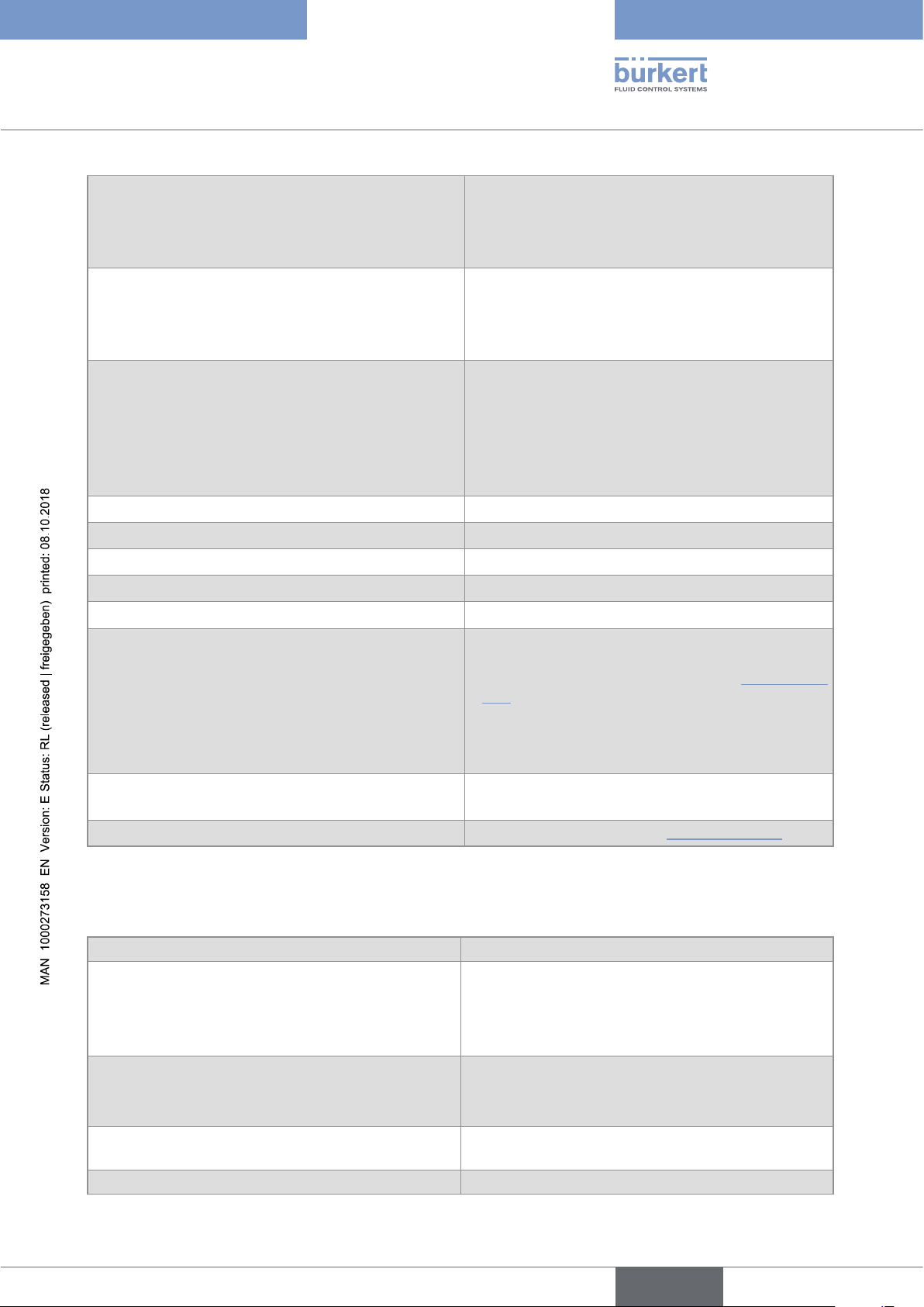
Table 6: Specifications of the industrial communication module
Network speed 10/100 mbps
Auto negotiation Yes
Auto MDI/MDI-X Yes
Switch function Yes
Network diagnostics Yes, via error telegram
MAC-ID
Device name Ethernet (factory setting) FLOWave (name can be changed)
6.10.1 Modbus TCP protocol
Individual identification number, stored in the module
and on the outside of the device (see rating plate)
TCP port 502
Protocol Internet protocol, version 4 (IPv4)
Network topology • Tree
• Star
• Line (open daisy chain)
IP configuration • Static IP address
• Not supported:
- BOOTP (Bootstrap Protocol)
- DHCP (Dynamic Host Configuration Protocol)
Transmission speed 10 and 100 MBit/s
Data transport layer EtherNet II, IEEE 802.3
Modbus function codes 1, 2, 3, 4, 15, 16, 23
Read/write register Maximum 125 read registers and 123 write registers per telegram
Message mode Server
Input (Target to Originator)
• All diagnostics and errors information has the highest priority and
can be read by a PLC (refer to the concerned protocol file available
at www.burkert.com).
• PDO: value, status, unit
• Device and modules: status
• Functions: value, status
28
PDO = Process Data Object, Target = Server, Originator = Client.
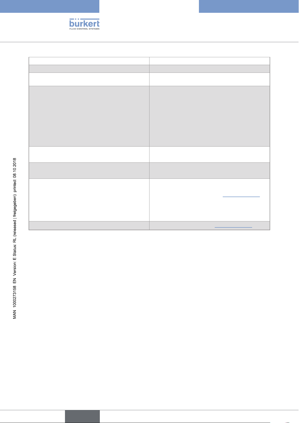
6.10.2 PROFINET protocol
Product type Compact field IO device
PROFINET IO specification V2.3
English
Page 29
Type 8098
Technical data
Network topology • Tree
• Star
• Ring (closed daisy chain)
• Line (open daisy chain)
Network management • LLDP (Link Layer Discovery Protocol)
• SNMP V1 (Simple Network Management Protocol)
• MIB-II (Management Information Base)
• Physical device
Additional supported features • DCP (Discovery and Configuration Protocol)
• VLAN- and priority tagging
• Shared device
• RTC (Real Time Cyclic) protocol: Class 1
• Not supported:
- IRT (In Real Time)
Transmission speed 100 MBit/s full duplex
Data transport layer EtherNet II, IEEE 802.3
Maximum supported conformance class CC-B
Media Redundancy (for ring topology) MRP client is supported
Minimum cycle time 10 ms
Input cyclic data (device to IO-controller or device to
IO-supervisor)
• All diagnostics and errors information has the
highest priority and can be read by a PLC (refer to
the concerned protocol file available at www.burkert.
com).
• PDO: value, status, unit
• Device and modules: status
• Functions: value, status
Application Relations (AR) The device can simultaneously process up to
2 IO-ARs, 1 Supervisor AR and 1 Supervisor DA AR.
GSDml file
Available at / Download from: www.burkert.com
PDO = Process Data Object
6.10.3 EtherNet/IP protocol
Protocol Internet protocol, version 4 (IPv4)
Network topology • Tree
• Star
• DLR (Device Level Ring) for closed daisy chain
• Linear for open daisy chain
IP configuration • Static IP address
• BOOTP (Bootstrap Protocol)
• DHCP (Dynamic Host Configuration Protocol)
CIP reset services
(Common Industrial Protocol)
Transmission speed 10 and 100 MBit/s
Reset service (type 0 or type 1) of the Identity object
29
English
Page 30
Type 8098
Technical data
Duplex modes Half duplex, full duplex, auto-negotiation
Data transport layer EtherNet II, IEEE 802.3
MDI modes
MDI, MDI-X, auto-MDI-X
(Medium Dependant Interface)
Predefined standard objects • Identity (0x01)
• Message Router (0x02)
• Assembly (0x04)
• Connection Manager (0x06)
• DLR (0x47)
• QoS (0x48)
• TCP/IP Interface (0xF5)
• EtherNet Link (0xF6)
Additional supported features • ACD (Address Conflict Detection
• Integrated switch
RPI (Requested Packet Interval) • minimum: 100 ms
• maximum: 9999 ms
Input (Consumer to Producer or Adapter to Scanner)
• All diagnostics and errors information has the highest
priority and can be read by a PLC (refer to the concerned protocol file available at www.burkert.com).
• PDO: value, status, unit
• Device and modules: status
• Functions: value, status
EDS file
Available at / Download from: www.burkert.com
PDO = Process Data Object, Consumer = Server, Producer = Client, Adapter = Server, Scanner = Client.
30
English
Page 31

Type 8098
Technical data
6.10.4 EtherCAT protocol
Industrial Ethernet interface X1, X2 • X1: EtherCAT IN
• X2: EtherCAT OUT
Maximum number of cyclic input and output data 512 bytes in total
Maximum number of
1024 bytes
cyclic input data
Maximum number of
1024 bytes
cyclic output data
Acyclic communication (CoE) • SDO
• SDO master-slave
• SDO slave-slave (depends on master capacity)
Type Complex slave
Fieldbus Memory Management Units (FMMUs) 8
Sync Managers 4
Transmission speed 100 Mbit/s
Data transport network Ethernet II, IEEE 802.3
EtherCAT® is a registered trademark and patented technology, licensed by Beckhoff Automation GmbH,
Germany
English
31
Page 32

Type 8098
32
English
Page 33

Type 8098
Installation in the pipe
7 INSTALLATION IN THE PIPE .......................................................................................................................................................34
7.1 Safety instructions .............................................................................................................................................................34
7.2 Preparing the device before installation into the pipe ...................................................................................35
7.2.1 Changing the position of the transmitter on the sensor ............................................................35
7.2.2 Switching positions of the blind cover and the display module ..............................................39
7.3 Recommendations for the installation into the pipe .......................................................................................41
7.4 Installing the device into the pipe ..............................................................................................................................44
7.4.1 Before installing the device into the pipe ......................................................................................44
7.4.2 Installing a device with clamp connections .................................................................................. 44
7.4.3 Installing a device with flange connections ..................................................................................44
English
33
Page 34

Type 8098
Installation in the pipe
7 INSTALLATION IN THE PIPE
7.1 Safety instructions
DanGer
Risk of injury due to electrical voltage.
▶ Before carrying out work on the system, disconnect the electrical power for all the conductors and isolate it.
▶ Observe all applicable accident protection and safety regulations for electrical equipment.
Risk of injury due to high pressure in the installation.
▶ Before any intervention in the installation, stop the circulation of fluid, cut off the pressure and drain the pipe.
▶ Before any intervention in the installation, make sure there is no pressure in the pipe.
▶ Observe the dependency between the fluid temperature and the fluid pressure for the fitting used.
If switched on for a prolonged time, risk of burns or fire due to hot device surfaces
▶ Do not touch with bare hands.
▶ Keep the device away from highly flammable substances and fluids.
Risk of burns due to high fluid temperatures.
▶ Do not touch with bare hands the parts of the device that are in contact with the fluid.
▶ Use safety gloves to handle the device.
▶ Before opening the pipe, stop the circulation of fluid and drain the pipe.
▶ Before opening the pipe, make sure the pipe is completely empty.
Risk of injury due to the nature of the fluid.
▶ Respect the prevailing regulations on accident prevention and safety relating to the use of dangerous fluids.
WarninG
Risk of injury due to non-conforming installation.
▶ The electrical and fluid installations must only be carried out by qualified and authorized personnel with the
appropriate tools.
WarninG
34
Risk of injury due to unintentional switch-on of the power supply or uncontrolled restart of the
installation.
▶ Take appropriate measures to avoid unintentional activation of the installation.
▶ Guarantee a set or controlled process restart after carrying out any device intervention.
English
Page 35

Type 8098
Installation in the pipe
WarninG
Risk of injury if the fluid pressure/temperature dependency is not respected.
▶ Observe the fluid temperature-pressure dependency. Refer to chpt. 6.6 Fluid data.
▶ Observe Pressure Equipment Directive 2014/68/EU.
caution
Risk of injury due to a heavy device.
A heavy device can fall down during transport or during installation and cause injuries.
▶ Transport, install and dismantle a heavy device with the help of another person.
▶ Use appropriate tools.
notice
The device will be damaged if you use a tool to turn the blind cover or the display module.
▶ Do not use a tool to turn the blind cover or the display module.
7.2 Preparing the device before installation into the pipe
The device is delivered as described in chpt. 5.1.
Before installing the device into the pipe, you may:
• change the position of the transmitter on the sensor. Refer to chpt. 7.2.1.
• switch positions of the display module and the blind cover. Refer to chpt. 7.2.2.
7.2.1 Changing the position of the transmitter on the sensor
These instructions are valid for all the versions of the device.
The Type SE98 transmitter can have four positions on the Type S097 flow sensor. See Fig. 12.
Fig. 12: Possible positions of the transmitter SE98
35
English
Page 36

Type 8098
Installation in the pipe
→ To change the position of the transmitter as it is described in chpt. 5.1, do the following:
For safety reasons and to comply with standard
UL 61010-1, the blind cover and the display module
are locked.
→ Prepare the unlocking magnetic key, which is
delivered with the device, to change the position of
the transmitter.
The blind cover or the display module is
locked
1. Put the magnetic key on the
to the display module. You should hear a soft click
indicating that the display module is unlocked. Do
not use a tool to turn the display module.
2. While the magnetic key is on the mark, turn
the display module by hand only from the locked
position to the unlocked position. If you cannot turn
the display module by hand, contact Bürkert.
3. Carefully lift the display module because
a cable connects the display module to the
transmitter.
4. Push the tab of the cable connector to disconnect
the display module from the transmitter.
mark related
The blind cover or the display module is
unlocked
36
5. Remove the display module and put it on a clean
surface to protect the seal from dirt.
Push the tab to
unlock the cable
connector
English
Page 37

Type 8098
Installation in the pipe
6. Use a size 3 hexagonal key to loosen the screw that
is marked with the arrow and that locks the transmitter to the flow sensor.
7. Hold the flow sensor with one hand and, with
the other hand, turn the transmitter by about
20 degrees counterclockwise.
8. Lift the transmitter carefully because a
cable connects the transmitter to the flow sensor.
9. If the seal is damaged, replace it. Apply a layer of
lithium soap grease to the new seal before you put
it in place.
10. If the seal is not located in the groove, put it back in
the groove.
Seal in the groove:
correct
Seal not in the groove:
NOT correct
English
37
Page 38

11. Turn the transmitter to the desired position.
Type 8098
Installation in the pipe
12.
Fold the cable in a Z-shape and make
sure the cable stays inside the transmitter.
13. Turn the transmitter by about 20 degrees
counterclockwise.
14. Screw the transmitter clockwise on the flow sensor
until the blind cover is perfectly parallel or perpendicular to the axis of the pipe.
15. Fasten the screw with a size 3 hexagonal
key to a tightening torque of 1.3 ±0.5 N·m
(0.96 ±0.37 ft·lbf)
38
English
Page 39

Type 8098
Installation in the pipe
16. Connect the display module to the transmitter.
17. Put the mark of the cover on the unlocked marking
of the housing and screw the cover clockwise
on the transmitter until the mark is on the locked
position. You should hear a click.
7.2.2 Switching positions of the blind cover and the display module
caution
Risk of injury due to a heavy device.
A heavy device can fall down during transport or during installation and cause injuries.
▶ Transport, install and dismantle a heavy device with the help of another person.
▶ Use appropriate tools.
These instructions are valid for all the versions of the device.
Upon delivery, a display module is screwed on the top and a blind cover is screwed on the housing side.
→ To switch positions of the display module and the blind cover, do the following:
For safety reasons and to comply with standard
UL 61010-1, the blind cover and the display module
are locked.
→ Prepare the unlocking magnetic key, which is
delivered with the device.
The blind cover or the display module is locked
1. Put the magnetic key on the
to the display module. You should hear a soft click
indicating that the display module is unlocked. Do
not use a tool to turn the display module.
mark related
2. While the magnetic key is on the mark, turn
the display module by hand only from the locked
position to the unlocked position. If you cannot turn
the display module by hand, contact Bürkert.
The display module is unlocked
39
English
Page 40

3. Carefully lift the display module because a cable
connects the display module to the transmitter.
4. Push the tab of the cable connector to disconnect
the display module from the transmitter.
5. Remove the display module and put it on a clean
surface to protect the seal from dirt.
Type 8098
Installation in the pipe
Push the tab to
unlock the cable
connector
6. Put the magnetic key on the mark related to
the blind cover. You should hear a click indicating
that the blind cover is unlocked. Do not use a tool
to turn the blind cover.
7. Turn the blind cover by hand only to the unlocked
position and remove it. If you cannot turn the blind
cover by hand, contact Bürkert.
8. Put the cable of the display module through the
front opening.
9. Connect the cable to the connector, as shown in
the figure.
10. Put the mark of the display module on the unlocked
marking of the housing and screw the cover
clockwise on the transmitter until the mark is on the
locked position.
Connect the cable here
40
English
Page 41

Type 8098
1 x DN
Installation in the pipe
11. Put the mark of the blind cover on the unlocked
marking of the top of the transmitter housing.
12. Screw the blind cover clockwise on the transmitter
until the mark is on the locked position. You should
hear a click.
The blind cover is locked.
7.3 Recommendations for the installation into the pipe
→ Protect this device against electromagnetic interference, ultraviolet rays and, when installed outdoors, the
effects of climatic conditions.
→ Make sure the DN of the measurement tube is suited to the flow velocity: refer to the data sheet of the device,
available at www.burkert.com.
→ Choose a location with enough free space to put the magnetic key on the symbol at the rear side of the device.
→ Install the device upstream a valve or any equipment that changes the pipe diameter or the pipe direction. If
the recommendation cannot be complied with, install the device in the pipe in such a way that the straight
downstream distances are satisfied depending on the design of the pipes, refer to standard ISO 9104:1991
and Fig. 13. If these recommendations cannot be complied with, contact Bürkert.
Flow direction
2 x 90° elbow
Control valve
40 x DN
1 x DN
joint
50 x DN
1 x DN
60 x DN
2 x 90°
elbow joint, 3
1 x DN
40 x DN
90° elbow joint or
T-piece
dimensional
Fig. 13: Upstream and downstream straight distances for special pipe designs
41
English
Page 42

Type 8098
Installation in the pipe
→ To allow proper self-draining and to respect the 3A and EHEDG requirements, install the device into a pipe
with a minimum angle against the horizontal. See Table 7.
Table 7: Minimum angle against the horizontal for proper self-draining
Type of process connection Standards the process connections conform to
Angle against the
horizontal
• DIN 32676 series A
clamp
• DIN 11864-3 series A
minimum 5°
• SMS 3017 / ISO 2852 for pipes according to
SMS 3008
flange DIN 11864-2 series A minimum 5°
• ASME BPE (DIN 32676 series C)
• DIN 32676 series A
clamp
minimum 3°
• DIN 11864-3 series B
• DIN 11864-3 series C
• DIN 11864-2 series B
flange
minimum 3°
• DIN 11864-2 series C
→ If the pipe is fitted with a thermal insulation, do not thermally insulate the measurement tube of the device to
make sure that the temperature in the device is less than 70°. Refer to Fig. 14 and, for the minimum supply
voltage, to chpt. 8.4.
Pipe insulation
Fig. 14: Thermal insulation of the pipe
No pipe insulation
42
English
Page 43

Type 8098
Installation in the pipe
→ To make sure the internal temperature of the transmitter with cable glands does not exceed the authorized
maximum value, install the device as recommended in Fig. 15.
→ To make sure the internal temperature of the transmitter does not exceed the authorized maximum value, install
an Ethernet version of the device as recommended in Fig. 16.
Recommended
1)
Not recommended
1)
Recommended
1) These orientations are valid for all the positions of the Type SE98 transmitter on the Type S097 flow sensor. Refer to
Fig. 12: Possible positions of the transmitter SE98 page 35
Fig. 15: Orientation of a device with cable glands to avoid effects of high liquid temperatures
1)
Recommended
Not recommended
Not recommended Recommended Recommended
1) These orientations are valid for all the positions of the Type SE98 transmitter on the Type S097 flow sensor. Refer to
Fig. 12: Possible positions of the transmitter SE98 page 35
Fig. 16: Orientation of an Ethernet version of the device to permit the heat dissipation
43
English
Page 44

Type 8098
Installation in the pipe
7.4 Installing the device into the pipe
caution
Risk of injury due to a heavy device.
A heavy device can fall down during transport or during installation and cause injuries.
▶ Transport, install and dismantle a heavy device with the help of another person.
▶ Use appropriate tools.
7.4.1 Before installing the device into the pipe
• Prepare the device as described in chpt. 7.2.
• Follow the recommendations given in chpt. 7.3.
7.4.2 Installing a device with clamp connections
The manufacturer of the device does not supply any gaskets for the process connections.
→ If the installation must be EHEDG-compliant and the device is fitted with clamp connections according to
ASME BPE (DIN 32676 series C), DIN 32676 series A, DIN 32676 series B or SMS 3017 / ISO 2852 for
pipes according to SMS 3008, use EHEDG-compliant gaskets from Combifit International B.V.
→ To make sure you use EHEDG-compliant gaskets, refer to the "EHEDG Position Paper" available on the
EHEDG website.
→ The clamp connections according to DIN 11864-3 series A, B and C are hygienic connections. You can use
any gaskets that are adapted to the process.
→ Make sure the gaskets on the clamp connections are in good condition.
→ Place gaskets adapted to the process (temperature, fluid type) in the grooves of the clamp connections.
→ Attach the clamp connections to the pipe with clamp collars.
7.4.3 Installing a device with flange connections
The flange connections according to DIN 11864-2 series A, B and C are hygienic connections. You can use
→
any gaskets that are adapted to the process.
→ Make sure the gaskets on the flange connections are in good condition.
→ Place gaskets adapted to the process (temperature, fluid type) in the grooves of the flange connections.
44
→ Use bolts with dimensions as given in the relevant flange standard and adapted to the process.
→ Tighten the bolts to a torque as given in the relevant flange standard to fix the fitting to the pipe.
English
Page 45

Type 8098
Electrical installation
8 ELECTRICAL INSTALLATION ......................................................................................................................................................46
8.1 Safety instructions .............................................................................................................................................................46
8.2 Specifications of the cable for the 5-pin M12 male connector ..................................................................48
8.3 Assembling and wiring the 5-pin M12 female connector (A-coding) .....................................................48
8.4 Connecting the device to a power supply .............................................................................................................49
8.5 Connecting the device to a büS / CANopen network .....................................................................................50
8.6 Activating the device internal termination resistor (only büS network) ................................................ 51
8.7 Specifications of the cables for the M20x1,5 cable glands (only device with cable glands) ....51
8.8 Specifications of the conductors for the 12 push-in terminal strip ........................................................52
8.9 Terminal assignment of the 12 push-in terminal strip ....................................................................................52
8.10 Opening the front of the transmitter ........................................................................................................................53
8.11 Wiring the device through the M20x1,5 cable glands in stainless steel (only device with cable
glands) ......................................................................................................................................................................................55
8.12 Wiring the device through the M20x1,5 cable glands in nickel plated brass (only device with
cable glands) .........................................................................................................................................................................57
8.13 Connecting the functional earth (device with 2 M20x1,5 cable glands) ...............................................59
8.14 Connecting the device to a 12...35 V DC power supply through the M20x1,5 cable glands
(only device with cable glands) ...................................................................................................................................60
8.15 Wiring output 1 (analogue) and output 3 configured as an analogue output (only device with
cable glands) .........................................................................................................................................................................61
8.16 Wiring output 2 (digital) and output 3 configured as a digital output (only device with cable
glands) ......................................................................................................................................................................................62
8.17 Knowing the status of the Ethernet network (only device with 2 4-pin M12 female connectors
- Ethernet version) .............................................................................................................................................................63
8.18 Specifications of the cables and conductors for the 4-pin M12 female connectors .....................64
8.19 Connecting the device to an Ethernet network (only device with 2 4-pin M12 female con-
nectors - Ethernet version) ............................................................................................................................................64
8.20 Connecting the functional earth (device with 2 4-pin M12 female connectors - Ethernet
version) .....................................................................................................................................................................................65
English
45
Page 46

Type 8098
Electrical installation
8 ELECTRICAL INSTALLATION
8.1 Safety instructions
DanGer
Risk of injury due to electrical voltage.
▶ Before carrying out work on the system, disconnect the electrical power for all the conductors and isolate it.
▶ Observe all applicable accident protection and safety regulations for electrical equipment.
Risk of injury due to high pressure in the installation.
▶ Before any intervention in the installation, stop the circulation of fluid, cut off the pressure and drain the pipe.
▶ Before any intervention in the installation, make sure there is no pressure in the pipe.
▶ Observe the dependency between the fluid temperature and the fluid pressure for the fitting used.
If switched on for a prolonged time, risk of burns or fire due to hot device surfaces
▶ Do not touch with bare hands.
▶ Keep the device away from highly flammable substances and fluids.
Risk of burns due to high fluid temperatures.
▶ Do not touch with bare hands the parts of the device that are in contact with the fluid.
▶ Use safety gloves to handle the device.
▶ Before opening the pipe, stop the circulation of fluid and drain the pipe.
▶ Before opening the pipe, make sure the pipe is completely empty.
Risk of injury due to the nature of the fluid.
▶ Respect the prevailing regulations on accident prevention and safety relating to the use of dangerous fluids.
WarninG
Risk of injury due to non-conforming installation.
▶ The electrical and fluid installations must only be carried out by qualified and authorized personnel with the
appropriate tools.
▶ Fit a circuit breaker or a switch to the electrical installation of the building in which the device is installed.
▶ Install the circuit breaker or the switch in an easily accessible place.
46
▶ Identify the circuit breaker or the switch as the disconnecting component for the electrical power supply to
the device.
▶ Install overload devices that are appropriate for electrical installation.
▶ Observe standard NF C 15-100 / IEC 60364.
English
Page 47

Type 8098
▶ Screw the plug to the 5-pin M12 male connector to a torque of 2 N·m.
▶ Make sure the unused M20x1,5 cable glands are sealed with the supplied plugs.
Electrical installation
WarninG
Risk of injury due to unintentional switch on of the power supply or uncontrolled restart of the
installation.
▶ Take appropriate measures to avoid unintentional activation of the installation.
▶ Guarantee a set or controlled process restart after carrying out any device intervention.
caution
Risk of injury due to a heavy device.
A heavy device can fall down during transport or during installation and cause injuries.
▶ Transport, install and dismantle a heavy device with the help of another person.
▶ Use appropriate tools.
notice
The device will be damaged if you use a tool to turn the blind cover or the display module.
▶ Do not use a tool to turn the blind cover or the display module.
notice
If you try to remove the nut from a stainless steel M20x1,5 cable gland, the device is no longer tight.
▶ Do not remove the nut of a stainless steel M20x1,5 cable gland. The nut of a stainless steel M20x1,5 cable
gland cannot be removed.
▶ Turn the nut until the stop. If you turn beyond the stop, the cable gland unscrews from the device and the
device is no longer tight.
notice
If the screwed plug of a 5-pin M12 male connector is removed, the device is not tight.
▶ If the 5-pin M12 male connector is not used, do not remove the screwed plug.
notice
The device with M20x1,5 cable glands is not tight if a cable gland is not used
• Use a high quality electrical power supply, filtered and regulated.
• Do not install the cables near high voltage or high frequency cables; if this cannot be avoided, observe a
minimum distance of 30 cm.
On a device with M20x1,5 cable glands, put only one cable in each cable gland.
To do the electrical installation of a device with 2 4-pin M12 female connectors (Ethernet version) that is
connected to an Ethernet network, observe standard ISO / IEC 61918.
47
English
Page 48

Type 8098
11,5
Electrical installation
8.2 Specifications of the cable for the 5-pin M12 male connector
Use a 5-pin M12 female connector (not supplied) to connect the 5-pin M12 male connector, for example the
M12 female connector with article number 917116.
If you use the M12 female connector with article number 917116, observe the specifications for the cable and
conductors, given in Table 8.
Table 8: Specifications of the cable and conductors for the M12 female connector with article number 917116
Specification Recommended value
• Electromagnetic protection (EMC)
• Shielded
• Cross section of the conductors
• Diameter of the cable
• Maximum operating temperature
• max. 0.75 mm
• 3...6.5 mm
• min. 80 °C
2
8.3 Assembling and wiring the 5-pin M12 female connector (A-coding)
To assemble and wire the 5-pin M12 female connector with article number 917116, do the following:
1 2
20
5,5
→ Completely loosen the nut [1].
→ Remove the rear part of the connector [2].
→ Put the cable through the nut and the rear part of
the connector.
→ Strip 20 mm of the cable.
→ Cut the central conductor so that its length is
11.5 mm.
→ Expose 5.5 mm of the other conductors.
48
→ Insert each conductor into the appropriate pin.
Refer to chpt. 8.5.
→ Pull the cable and tighten the connector nut.
Fig. 17: M12 multipin connector with article number 917116 (not provided)
→ Plug the 5-pin M12 female connector on the 5-pin M12 male connector of the device.
→ Tighten the M12 female connector with your hand.
English
Page 49

Type 8098
Electrical installation
8.4 Connecting the device to a power supply
The device is wired in the factory to be easily energized through the 5-pin M12 male connector.
→ Connect the device with 2 4-pin M12 female connectors (Ethernet version) to a 12...35 V DC power supply
through the 5-pin M12 male connector; Refer to chpt. 8.5.
A device with 2 4-pin M12 female connectors (Ethernet version) must be energized through the 5-pin
M12 male connector.
→ Connect the device with M20x1,5 cable glands to a 12...35 V DC power supply:
• either through the 5-pin M12 male connector, refer to chpt. 8.5.
• or through the M20x1,5 cable glands and the terminal strip located in the transmitter housing. Refer to
chpt. 8.14 for the wiring procedure.
The minimum voltage to be supplied depends on the version of the device, on the fluid temperature and on the
ambient operating temperature: see Fig. 18 and Fig. 19.
Voltage not allowed
Ambient temperature °C
80
70
60
50
40
30
20
10
0
-20 0 20 40 60 80 100 120 140 160
-10
-20
Temperature authorized for a limited duration
Supply voltage V DC
35
30
25
20
15
10
5
Fluid temperature °C
Fig. 18: Minimum supply voltage depending on the ambient temperature and the fluid temperature, device with 2
M20x1,5 cable glands and 1 5-pin M12 male connector
Voltage not allowed
Ambient temperature °C
80
70
60
50
40
30
20
10
0
-20 0 20 40 60 80 100 120 140 160
-10
-20
Temperature authorized for a limited duration
Supply voltage V DC
35
30
25
20
15
10
5
Fluid temperature °C
Fig. 19: Minimum supply voltage depending on the ambient temperature and the fluid temperature, device with 2 4-pin
M12 female connectors and 1 5-pin M12 male connector (Ethernet version)
English
49
Page 50

Type 8098
4
Electrical installation
8.5 Connecting the device to a büS / CANopen network
The 5-pin M12 male connector (A-coding) is used to connect the device:
• To a 12...35 V DC power supply and/or
• To the büS / CANopen network.
Risk of damage to the device if an M12 connector is unused.
• Put a protection cap on all the unused M12 connectors.
Malfunction of the internal and external communication if the 5-pin M12 male connector is not used.
• Make sure pins 4 and 5 are not in contact with each other and not in contact with the other pins.
→ If the device is connected to büS and at one end of büS, either install a 120 W termination resistor in the line
or activate the device internal termination resistor: see chpt. 8.6.
If a device with 2 4-pin M12 female connectors (Ethernet version) is connected to an Ethernet network,
you must connect it to a büS / CANopen network for the configuration of the device with the software
Bürkert Communicator.
• Pin 1: CAN shield
2
3
Fig. 20: Pin assignment of the 5-pin M12 male connector
5
1
• Pin 2: 12...35 V DC
• Pin 3: GND
• Pin 4: CAN_H
• Pin 5: CAN_L
50
Cable and conductors
connected inside the
device to the 5-pin M12
male connector
Fig. 21: Wiring ex works of the 12 push-in terminal strip to the 5-pin M12 male connector
English
Page 51

Type 8098
Electrical installation
8.6 Activating the device internal termination resistor (only büS network)
The device has an internal termination resistor that can be activated if the device is installed at one end of büS.
If you activate the device internal termination resistor, do not install a termination resistor at the same end of büS.
To activate the device internal termination resistor, do the following:
→ Go to the CONFIGURATION view.
→ General settings
→ Confirm to access the Parameter view.
→ büS
→ Advanced
→ Termination resistor
→ On
→ Save.
The internal termination resistor is activated.
8.7 Specifications of the cables for the M20x1,5 cable glands (only device with cable glands)
Table 9: Specifications of the cables for the M20x1.5 cable glands in nickel plated brass
Specification of the cables Recommended value
Electromagnetic protection (EMC) Shielded
Diameter 5...14 mm
Maximum operating temperature min. 90 °C
Table 10: Specifications of the cables for the M20x1.5 cable glands in stainless steel
Specification of the cables Recommended value
Electromagnetic protection (EMC) Shielded
Diameter 6...12 mm
Maximum operating temperature min. 100 °C
English
51
Page 52

Type 8098
123456789111210
Electrical installation
8.8 Specifications of the conductors for the 12 push-in
terminal strip
Table 11: Specifications of the conductors for the terminal strip
Specification of the conductors Recommended value range
Cross section of a solid conductor H05(07) V-U 0,25...1,5 mm
Cross section of a stranded conductor H05(07) V-K,
0,25...1,5 mm
2
2
with a wire ferrule but without collar
2
Cross section of a stranded conductor H05(07) V-K,
0,25...0,75 mm
with a wire ferrule with a plastic collar
2
Cross section of other kinds of conductors 0,2...1,5 mm
(AWG24... AWG16)
8.9 Terminal assignment of the 12 push-in terminal strip
The terminal strip located in the transmitter housing has 12 push-in terminals.
→ To access the 12 push-in terminal strip, open the front of the transmitter; See chpt. 8.10.
Green LED
• Green LED:
- flashes slowly if the operation of the device is correct.
- flashes quickly if there is a communication problem with the measurement board.
• Orange LED lit if the related digital output is switched to ON (only device with 2 M20x1,5 cable glands)
• Terminal 1: GND (blue conductor, factory wired, internally connected to the 5-pin M12 male connector)
• Terminal 2: CAN_L (grey conductor, factory wired, internally connected to the 5-pin M12 male connector)
• Terminal 3: Shield (brown conductor, factory wired, internally connected to the 5-pin M12 male connector)
• Terminal 4: CAN_H (black conductor, factory wired, internally connected to the 5-pin M12 male connector)
• Terminal 5: 12...35 V DC (white conductor, factory wired, internally connected to the 5-pin M12 male connector)
On a device with 2 4-pin M12 female connectors (Ethernet version), do not use terminals 6 to 12.
Orange LED
(only device with 2 M20x1,5 cable glands)
• Terminal 6: GND (for the connection of the power supply through the M20x1,5 cable glands)
• Terminal 7: negative output 3 (analogue output or digital output)
• Terminal 8: positive output 3 (analogue output or digital output)
• Terminal 9: negative output 2 (digital output)
• Terminal 10: positive output 2 (digital output)
• Terminal 11: negative output 1 (analogue output)
• Terminal 12: positive output 1 (analogue output)
52
Fig. 22: Terminal assignment of the 12 push-in terminal strip located in the transmitter housing
English
Page 53

Type 8098
Electrical installation
Fig. 23: Wiring ex works of the 12 push-in terminal strip
→ If you need to disconnect a conductor, first push the terminal with a slot screwdriver 3.0 mm (any length) and
a force of max. 40 N.
8.10 Opening the front of the transmitter
To open the front of the transmitter housing, remove either the blind cover or the display module.
Procedure to open the front of the transmitter if the blind cover is on the front of the device
1. Put the magnetic key on the mark related to
the blind cover. You should hear a click indicating
that the blind cover is unlocked. Do not use a tool
to turn the blind cover.
2. Turn the blind cover by hand to the unlocked
position and remove it.
Fig. 24: Procedure to open the front of the transmitter if the blind cover is on the front of the device
English
53
Page 54

Type 8098
Electrical installation
Procedure to open the front of the transmitter if the display module is on the front of the device
1. Remove the blind cover from the top of the
transmitter.
2. Put the magnetic key on the
mark related
to the display module. You should hear a click indicating that the display module is unlocked. Do not
use a tool to turn the display module.
3. Turn the display module by hand to the unlocked
position.
4. Carefully pull the display module
because a cable connects the display module to
the transmitter.
5. Push the tab of the cable connector to disconnect
the display module from the transmitter.
6. Remove the display module and put it on a clean
surface to protect the seal from dirt.
Push the tab to unlock
the cable connector
54
Fig. 25: Procedure to open the front of the transmitter if the display module is on the front of the device
English
Page 55

Type 8098
100 mm ±5
8 mm
Electrical installation
8.11 Wiring the device through the M20x1,5 cable glands in stainless steel (only device with cable glands)
Put only one cable in each cable gland.
→ Prepare cables that obey the specifications given in
chpt. 8.7 and chpt. 8.8.
→ To open the front of the transmitter, follow the
instructions given in chpt. 8.10.
1. Use a size 10 hexagonal key to loosen the 2 screws
of the functional earth plate.
2 screws
2. Strip 100 mm of the cable.
3. Reduce the shield to 20 mm.
4. Expose 8 mm of the conductors.
5. Remove the blind plug of the cable gland.
6. Do not remove the nut of a stainless steel M20x1,5
cable gland. The nut of a stainless steel M20x1,5
cable gland cannot be removed.
7. Turn the nut until the stop. If you turn beyond the
stop, the cable gland unscrews from the device and
the device is no longer tight.
8. Put the cable through the cable gland as shown in
the figure.
9. Use a size 22 hexagonal key to tighten the cable
gland to a torque of 5 N·m (3.7 ft·lbf).
10. Attach each cable to the functional earth plate. The
shield must be in contact with the functional earth
plate.
20 mm
55
English
Page 56

11. Put the functional earth plate in its original place.
Type 8098
Electrical installation
12. Use a size 10 hexagonal key to tighten the 2 screws
Functional earth
of the functional earth plate to a torque of 0.2 N·m
(0.15 ft·lbf).
IT IS NOT MANDATORY TO
CONNECT THE DEVICE TO A
PROTECTIVE EARTH - MEANT FOR
FUTURE USE
13. Put each conductor in the correct terminal of the terminal strip.
14. To connect the 12...35 V DC power supply through the cable glands, refer to chpt. 8.14.
2 screws
15. To connect the outputs, refer to chpt. 8.15 and chpt. 8.16.
16. Connect the functional earth conductor. See chpt. 8.13.
17. If the display module is removed, connect it back.
18. Close the front and the top of the transmitter housing.
Fig. 26: Wiring the device through the M20x1,5 cable glands in stainless steel
56
English
Page 57

Type 8098
100 mm ±5
8 mm
Electrical installation
8.12 Wiring the device through the M20x1,5 cable glands in nickel plated brass (only device with cable glands)
Put only one cable in each cable gland.
→ Prepare cables that obey the specifications given in
chpt. 8.7 and chpt. 8.8.
→ To open the front of the transmitter, follow the
instructions given in chpt. 8.10.
1. Use a size 10 hexagonal key to loosen the 2 screws
of the functional earth plate.
2 screws
2. Strip 100 mm of the cable.
3. Reduce the shield to 20 mm.
4. Expose 8 mm of the conductors.
5. Remove the nut of the cable gland.
6. If the cable diameter is between 5 and 9 mm, put
the cable through the cable gland as shown in the
figure.
7. Use a size 24 hexagonal key to tighten the cable
gland to a torque of 10 N·m (7.4 ft·lbf).
8. If the cable diameter is between 9 and 14 mm:
→ Vertically put a screwdriver between the two seals.
→ Lift the inner seal and remove it.
→ Put the cable through the cable gland.
→ Use a size 24 hexagonal key to tighten the cable
gland to a torque of 10 N·m (7.4 ft·lbf).
20 mm
57
English
Page 58

9. Attach each cable to the functional earth plate. The
shield must be in contact with the functional earth
plate.
10. Put the functional earth plate in its original place.
Type 8098
Electrical installation
11. With an hexagonal key size 10, tighten the 2 screws
Functional earth
of the functional earth plate to a torque of 0.2 N·m
(0.15 ft·lbf).
IT IS NOT MANDATORY TO
CONNECT THE DEVICE TO A
PROTECTIVE EARTH - MEANT FOR
FUTURE USE
12. Put each conductor in the correct terminal of the terminal strip.
13. To connect the 12...35 V DC power supply through the cable glands, refer to chpt. 8.14.
2 screws
58
14. To connect the outputs, refer to chpt. 8.15 and chpt. 8.16.
15. Connect the functional earth conductor. See chpt. 8.13.
16. If the display module is removed, connect it back.
17. Close the front and the top of the transmitter housing.
Fig. 27: Wiring the device through the M20x1,5 cable glands in nickel plated brass
English
Page 59

Type 8098
Electrical installation
8.13 Connecting the functional earth (device with 2 M20x1,5 cable glands)
→ For a proper function of device always connect the yellow/green functional earth conductor:
- either to the functional earth plate in the transmitter housing (see Fig. 29 in chpt. 8.14),
- or to the functional earth screw on the outer surface of the transmitter housing (see Fig. 28).
If you connect the conductor to the functional earth screw:
→ Use a ring cable lug for M4 screw.
→ Tighten the M4 screw to a torque between 1.8...2 N·m (1.3...1.4 ft·lbf).
Fig. 28: Functional earth screw on the outer surface of the device
English
59
Page 60

Type 8098
Electrical installation
8.14 Connecting the device to a 12...35 V DC power supply through the M20x1,5 cable glands (only device with cable glands)
1. Use a 3.0 mm slot screwdriver (any length) and a force of max. 40 N to push the terminal 5 and disconnect
the white conductor. Do not cut the white conductor.
2. Insulate the white conductor.
3. Connect the power supply as shown in Fig. 29.
To connect to the positive 12...35 V DC power supply for
the device through a cable gland
To connect to the negative power supply for the device
Green LED flashes slowly if
the operation of the device
is correct
through a cable gland
Internally con-
nected to the
5-pin M12 male
connector
11234567891 1210
Insulated white
conductor
To connect to the functional
earth through a
cable gland
60
Fig. 29: Connecting the 12...35 V DC power supply through the M20x1,5 cable glands
English
Page 61

Type 8098
11234567891 1210
Electrical installation
Fig. 30: Device connected to a 12...35 V DC power supply through the M20x1,5 cable glands
8.15 Wiring output 1 (analogue) and output 3 configured as an analogue output (only device with cable glands)
notice
Risk of short-circuit if the configuration of output 3 is wrong.
▶ Before wiring output 3 as an analogue output, make sure output 3 is configured as an analogue output in the
Parameter menu of the outputs. See chpt. 17.2 Changing the type of output 3.
An analogue output can be wired either in sourcing mode or in sinking mode.
+-
12-35 V DC
Power supply for
output 3
+-+-
12-35 V DC
Power supply for
+-
output 1
4...20 mA input, at
external instrument,
connected to output 3
Fig. 31: Wiring the analogue outputs
4...20 mA input, at
external instrument,
connected to output 1
61
English
Page 62

Type 8098
11234567891 1210
Electrical installation
8.16 Wiring output 2 (digital) and output 3 configured as a digital output (only device with cable glands)
notice
Risk of short-circuit if the configuration of output 3 is wrong.
▶ Before wiring output 3 as an analogue output, make sure output 3 is configured as an analogue output in the
Parameter menu of the outputs. See chpt. 17.2 Changing the type of output 3.
A digital output can be wired either in NPN mode or in PNP mode.
Orange LED is lit if the
related digital output is
switched to ON
12-35 V DC
Power supply for
output 3
Fig. 32: Wiring the digital outputs
+-
Load connected to
output 3
+-
+-
12-35 V DC
Power supply for
output 2
+-
Load connected to
output 2
62
English
Page 63

Type 8098
X1 X2
Electrical installation
8.17 Knowing the status of the Ethernet network (only
device with 2 4-pin M12 female connectors Ethernet version)
The status of the Ethernet network is indicated by LEDs. The LEDs are located on the industrial communication
module in the transmitter housing.
→ To see the LEDs, open the front of the transmitter housing i.e. by removing either the blind cover or the display
module; see chpt. 8.10.
Interface X1
(Ethernet Port Switch):
Link LED (yellow)
Link/Act LED (green)
Connection to the PLC:
Error LED (yellow)
RUN LED (green)
Fig. 33: LEDs for status of the Ethernet network
Description of the LEDs:
LED status Description / cause of error Procedure
RUN LED
(green)
Error LED
(yellow)
ON Connection active. OFF Connection not active. Check cables
ON Connection not active. Check cables
OFF Connection active. -
Interface X2
(Ethernet Port Switch):
Link/Act LED (green)
Link LED (yellow)
Table 12: LED for status of the connection to the PLC
LED status Description / cause of error Procedure
Link/Act
LED
(green)
Link LED
(yellow)
Table 13: LEDs for status of the interfaces X1 and X2 (for connection to an Ethernet network)
ON Rapid flashing: connection to the higher-level pro-
tocol layer EtherNet/IP has been established. Data is
being transmitted.
Slow flashing: there is no connection to the protocol
layer. This is usually the case for approx. 20 seconds
following a restart.
OFF No connection to the network available. Check cables
ON Connection to the network available. OFF No connection to the network available. Check cables
63
English
Page 64

Type 8098
1
2
34
Electrical installation
8.18 Specifications of the cables and conductors for the 4-pin M12 female connectors
Table 14: Specifications of the cables and conductors for the 4-pin M12 female connectors
Specification of the cables and conductors Recommended value
Electromagnetic protection (EMC) Shielded conductor with minimum STP
Minimum category CAT-5
Maximum length 100 m
Maximum operating temperature min. 90 °C
8.19 Connecting the device to an Ethernet network
(only device with 2 4-pin M12 female connectors Ethernet version)
The 2 4-pin M12 female connectors (D-coding) are used to connect the device to an Ethernet network.
Risk of damage to the device if any M12 connector is unused.
• Put a protection cap on all the unused M12 connectors.
If a device with 2 4-pin M12 female connectors (Ethernet version) is connected to an Ethernet network,
you must connect it to a büS / CANopen network for the configuration of the device with the software
Bürkert Communicator.
If a device is connected to an Ethernet network, the measured process values are transmitted via the Ethernet
network.
Each 4-pin M12 female connector (D-coding) has the same pin assignment: See Fig. 34.
• Pin 1: Transmit +
• Pin 2: Receive +
• Pin 3: Transmit –
• Pin 4: Receive –
Fig. 34: Pin assignment of the 4-pin M12 female connector
64
English
Page 65

Type 8098
Electrical installation
X1 X2
Cable and conductors connected
inside the device from X1 to
the upper 4-pin M12 female
connector
Cable and conductors connected
inside the device from X2 to
the middle 4-pin M12 female
connector
Cable and conductors connected inside
the device from the 12 push-in terminal
strip to the 5-pin M12 male connector
Fig. 35: Wiring ex works of the device with 2 4-pin M12 female connectors (Ethernet version)
8.20 Connecting the functional earth (device with 2 4-pin M12 female connectors - Ethernet version)
For a proper function of device always connect the yellow/green functional earth conductor to the functional earth
screw on the outer surface of the transmitter housing.
→ Use a ring cable lug for M4 screw.
→ Connect the functional earth conductor to the functional earth screw, see Fig. 36.
→ Tighten the M4 screw to a torque between 1.8...2 N·m (1.3...1.4 ft·lbf).
Fig. 36: Functional earth screw on the outer surface of the device
65
English
Page 66

Type 8098
66
English
Page 67

Type 8098
Doing the settings
9 HOW TO DO THE SETTINGS ..................................................................................................................................................... 68
9.1 Safety instructions .............................................................................................................................................................68
9.2 Available software to do the settings ......................................................................................................................68
9.3 Preparing the Bürkert Communicator software .................................................................................................68
9.4 Display module: description of the user interface ............................................................................................70
9.4.1 Description of the display .................................................................................................................71
9.4.2 How to use the touch sensitive keys .............................................................................................72
9.4.3 Minimum and maximum values when entering a numerical value ...........................................72
9.5 Available login user levels .............................................................................................................................................72
9.6 Default settings ....................................................................................................................................................................73
9.7 Menu structure .....................................................................................................................................................................74
9.7.1 Opening or closing the context menu in any view (display module only) .............................. 75
9.7.2 Adding your own context menu items (shortcuts, display module only) ................................76
9.7.3 Reading out the messages generated by the device.................................................................77
9.7.4 Changing the login user level if the adjustment is not protected through passwords .......77
9.7.5 Changing the login user level if the adjustment is protected through passwords ..............78
9.7.6 Logging out from the Advanced user, Installer or Bürkert user level ...............................78
9.7.7 Reading out the access path to a menu item (display module only) ......................................79
9.8 How to navigate in the menus and to adjust values .......................................................................................79
9.8.1 Adjusting a percentage or selecting a value in a list ..................................................................79
9.8.2 Navigating in a wizard and adjusting numbers ............................................................................80
9.8.3 Setting negative or positive numbers ............................................................................................81
9.8.4 Entering a name ..................................................................................................................................82
9.8.5 Activating or deactivating a feature ................................................................................................83
English
67
Page 68

Type 8098
How to do the settings
9 HOW TO DO THE SETTINGS
9.1 Safety instructions
WarninG
Risk of injury due to non-conforming adjustment.
Non-conforming adjustment could lead to injury and damage the device and its surroundings.
▶ The operators in charge of adjustment must have read and understood the contents of the Operating
Instructions.
▶ In particular, observe the safety recommendations and intended use.
▶ The device/installation must only be adjusted by suitably trained staff.
9.2 Available software to do the settings
The settings of the device can be done with:
• the Type ME31 display module. The device can be equipped with a display module or not.
• the Type 8920 Bürkert Communicator software, which must be installed on a PC.
The menu structure is the same in the display module and in the Bürkert Communicator software.
→ To do the settings of the device with the Type ME31 display module, refer to the next chapters of these Operating
Instructions, starting with chpt. 9.4 Display module: description of the user interface.
→ To use the Bürkert Communicator software, first prepare the necessary hardware and the software. Refer to
chpt. 9.3. Then do the settings as described in these Operating Instructions, starting with chpt. 9.4.3 Minimum
and maximum values when entering a numerical value.
→ To use some specific functions that are only available with the Bürkert Communicator software, refer to the
Type 8920 Operating Instructions, available on the internet at www.burkert.com
→ To get detailed information on the software of the Type ME31 display module, refer to the related Operating
Instructions, available on the internet at www.burkert.com
9.3 Preparing the Bürkert Communicator software
To do the settings with the Type 8920 Bürkert Communicator software, do the following steps:
1. Buy the USB-büS interface set with article number 772426.
68
2. Download the latest version of the Type 8920 Bürkert Communicator software from www.burkert.com
3. Install the Bürkert Communicator software on a PC. Obey the installation recommendations given in the
USB-büS interface set. During installation, the büS stick must not be inserted at the PC.
4. Screw the termination resistance into the Y plug or activate the device internal termination resistor (see
chpt. 11.6.3).
5. Screw the female M12 connector at the end of the delivered cable into the Y plug.
6. Insert the micro-USB of the cable into the delivered büS stick.
English
Page 69

Type 8098
How to do the settings
7. Insert the appropriate power adapter into the AC/DC adapter.
8. Connect the cable of the AC/DC adapter to the related connector of the female M12 connector.
micro-USB
büS stick
Termination
resistance
Cable of the AC/DC adapter
Y plug
Female M12
connector
Power adapter
AC/DC adapter
Fig. 37: Assembled connection cables, plugs and büS stick
9. Screw the Y plug on the male M12 connector of the device.
10. Insert the büS stick into a USB port of the PC.
11. Wait until the Windows pilot of the büS stick has been completely installed on the PC.
12. Connect the AC/DC adapter to the power supply.
13. Start the Bürkert Communicator software.
14. Click on
in the Bürkert Communicator software to establish the communication between the Bürkert Com-
municator software and the device. A window opens.
15. Select büS-Stick.
16. Choose the port Bürkert büS Stick, click on Finish and wait until the device symbol appears in the list of
devices.
17. In the list of devices, click on the symbol related to the device: the menu structure for the device is displayed.
English
69
Page 70

Type 8098
How to do the settings
9.4 Display module: description of the user interface
To get detailed information on the display software, refer to the Operating Instructions of the Type ME31
display software, available on the internet at www.burkert.com
The user interface is made up of a display and touch sensitive keys.
View 1 of 4
Display
Volume flow
View 2
30.1
CONFIGURATION
Navigation keys OK keyBACK key
Fig. 38: Overview of the user interface
l/min
70
English
Page 71

Type 8098
How to do the settings
9.4.1 Description of the display
Symbol of the active user level. See chpt. 9.5 Available login user levels.
Symbol of the device status
To the DIAG-
NOSTICS menu, by
pressing
Display
Parameter
Brightness 56%
Contrast 64%
Screen saver [+]
DIAGNOSTICS
Information bar
MAINTENANCE
Name of the customized view or of the menu
SAW sensor
Parameter
Stand. meas. values [+]
Add. meas. values [+]
Diag. events [+]
DIAGNOSTICS
Refresh time Long
More menu items are available
The symbol [+] at the end of a menu item means that sub-menu items are available.
Title of the menu or of
the menu item
MAINTENANCE
To the MAINTENANCE
menu, by pressing
Fig. 39: Description of the display (examples)
English
71
Page 72

9.4.2 How to use the touch sensitive keys
The highlighted terms are related to menus or menu items.
Table 15: How to use the keys
Key Description
Short press: to go back to the parent menu or to the parent view. This key is called BACK in the
display messages.
If the user makes changes but does not save these, then a message is displayed asking if the
changes should be saved.
Long press: to go back to View 1
If one or both keys are displayed:
• To switch between views, from the left to the right and vice versa. Only possible
between the views that can be customized and the CONFIGURATION view, and
between the Diagnostics, Parameter and Maintenance views.
Type 8098
How to do the settings
• To select the digit to the left or the digit to the right when you are asked to enter a
value.
• To select a Menu item.
• To select an option or to change a value.
This key is called OK in the display messages.
Short press:
• To confirm a selection.
• To save a choice.
• To go to the next screen of the wizard.
Long press: to open the context menu
9.4.3 Minimum and maximum values when entering a numerical value
When you are requested to enter or to change a numerical value, the minimum and maximum authorized values
are always displayed.
9.5 Available login user levels
72
The following 4 login user levels are available to operate or adjust the device:
• the basic user level, which is the level with the least functions,
• the Advanced User user level,
• the Installer user level (default),
• the Bürkert user level.
By default, the device adjustment is not protected by passwords.
English
Page 73

Type 8098
How to do the settings
Table 16 shows the symbol displayed in the information bar, depending on the user level that is active on the
device, and what can be done with each type of user level.
Symbol1) User level Description
• No password is required.
No symbol
Basic user
• The menu items with the symbol
enable read-only access.
• Not all the menu items that are available with a higher user level are displayed.
• Password required, if the password protection is active (see chpt. 11.15).
Default password is 005678.
Advanced
user
• The menu items with the symbol
enable read-only access.
• Not all the menu items that are available with a higher user level are displayed.
• Password required, if the password protection is active (see chpt. 11.15).
Default password is 001946.
Installer
• This level is active by default (and by default, password protection is switched
off).
• All the available menu items can be adjusted.
• Password required, if the password protection is active (see chpt. 11.15).
Bürkert
Table 16: Possible login user levels
1)
displayed in the information bar, only if the adjustment is protected through passwords.
• Only for Bürkert service.
→ If you have forgotten your passwords, you can restore the default passwords with the Type 8920 Bürkert Com-
municator software. Refer to the related Operating Instructions.
9.6 Default settings
You can find the default settings of the device in the CANopen supplement for the Type 8098 at www.burkert.
com
→ Before making any changes to the settings, use the Bürkert Communicator software to print a pdf file with all
the default settings of the device.
73
English
Page 74

9.7 Menu structure
Type 8098
How to do the settings
Level 1
To navigate through the list of
available menu items
SAW sensor
Diagnostics
Device [+]
Diag. events [+]
Level 2
Sensor [+]
CONFIGURATION
F
SAW sensor
T
Configuration view
Press to access the displayed
menu item (for example, the item
"SAW sensor")
SAW sensor
Parameter
PARAMETER
Stand. meas. values [+]
Add. meas. values [+]
Diag. events [+]
DIAGNOSTICS
Refresh time Long
View 1
MAINTENANCE
View 1 of 4
Volume flow
30.1
CONFIGURATION
First view, displayed after
energizing the device, that
can be changed by the user
Long press, from any view
Device information [+]
Flow direction Standa...
PARAMETER
Calibration [+]
Simulation [+]
l/min
SAW sensor
Maintenance
View 2
*
74
Diagnostics view
Reading out the values
related to the diagnostics
Parameter view
Reading out or setting the
parameters
* to display the next 3 views that can be added and changed by the user.
Fig. 40: Menu structure of the FLOWave
A context menu can be opened in any view: see chpt. 9.7.1.
English
Maintenance view
Reading out or setting
the values related to the
maintenance
Page 75

Type 8098
How to do the settings
9.7.1 Opening or closing the context menu in any view (display module only)
The user can open a context menu in any view. The content depends on the active view.
To open the context menu:
→ Press and hold .
The context menu is open.
To close the context menu without leaving the active view:
→ Press .
The context menu is closed.
Context menu content depending on the view:
View Menu items of the context menu
Views 1 to 4
CONFIGURATION
Messages overview
Add new view
Delete this view
Change layout
Change title
Change value
Change unit
Fractional digits
Change user level
Messages overview
Change user level
To display the list of messages generated by the device. See
chpt. 9.7.3.
To add a new view or to delete the displayed view.
To choose to display 1, 2 or 4 values or a trend of 1 or 2 values.
To change the title of the displayed view.
To change the value(s) or the units of the values displayed in the
view.
Not available for trends.
To choose whether a value of the view is displayed as a whole
number or with one or more decimals.
To change the user level. See chpt. 9.7.4 or chpt. 9.7.5.
To display the list of messages generated by the device.
To change the user level.
Parameter
Maintenance
Diagnostics
Messages overview
Where am I?
Add shortcut
Delete shortcut
Change user level
To display the list of messages generated by the device.
To display the access path to the displayed menu item. See
chpt. 9.7.7.
To create or delete your own context menu items (see
chpt. 9.7.2).
To change the user level.
75
English
Page 76

View Menu items of the context menu
Type 8098
How to do the settings
Messages overview
Save
in a menu
Table 17: Context menu depending on the view
Where am I?
Add shortcut
Delete shortcut
Change user level
To display the list of messages generated by the device.
To save the changes.
To display the access path to the displayed menu item. Not
available in the wizard.
To create or delete your own context menu items (see
chpt. 9.7.2).
To change the user level.
9.7.2 Adding your own context menu items (shortcuts, display module only)
If you are in the Parameter, Maintenance or Diagnostics view or in a menu, you can add up to 3 shortcuts to
the context menu. These shortcuts then appear in every context menu and allow the user to jump directly to the
selected view or menu item.
Parameter
Language
English
Where am I?
German
Change user level
French
> RESET TOT 1
Fig. 41: Shortcut example
To add a shortcut to the context menu:
Example of a shortcut
→ Go to the view or menu for which a shortcut should be created.
→ Press and hold to open the context menu.
→ Add shortcut
→ Enter a name for this shortcut: see chpt. 9.8.4 Entering a name.
→ OK to confirm the name entered. Save.
The shortcut to this view or to this menu is added to the context menu.
To delete a shortcut from the context menu:
→ Press and hold to open the context menu.
76
→ By using the shortcut to be deleted, go to the view or menu item.
English
Page 77

Type 8098
How to do the settings
→ Press and hold to open the context menu.
→ Delete shortcut Confirm.
The shortcut to this view or to this menu item is deleted from the context menu.
9.7.3 Reading out the messages generated by the device
The device generates messages to inform you, for example, that a problem has occurred or that a process value
limit has been reached.
→ To read out the messages in the Bürkert Communicator software, refer to the Operating Instructions Type
8920, available on the internet at www.burkert.com
Do the following to display the generated messages on the display module:
→ Long press, to open the context menu.
→ Messages overview Confirm.
The generated messages are displayed. Some messages can be acknowledged.
9.7.4 Changing the login user level if the adjustment is not protected through passwords
By default:
• the Installer user level is active on the device,
• the adjustment is not protected through passwords,
• the symbol related to the Installer user level is not displayed in the information bar.
You can only change to the Bürkert user level.
→ To change the login user level in the Bürkert Communicator software, refer to the Operating Instructions Type
8920, available on the internet at www.burkert.com
Do the following to change the login user level on the display module:
→ Long press, to open the context menu.
→ Change user level Confirm.
→ Choose the Bürkert user level Confirm.
→ Enter the password Confirm.
The user level is changed.
→ To activate the adjustment protection through passwords, refer to chpt. 11.15.
77
English
Page 78

Type 8098
How to do the settings
9.7.5 Changing the login user level if the adjustment is protected through passwords
If the adjustment is protected through passwords, the symbol related to the active user level is displayed in the
information bar.
→ To change the login user level in the Bürkert Communicator software, refer to the Operating Instructions Type
8920, available on the internet at www.burkert.com
Do the following to change the login user level on the display module:
→ Long press, to open the context menu.
→ Change user level Confirm.
→ Choose Logout (not available if the basic user is logged in) Confirm.
→ Long press, to open the context menu.
→ Change user level Confirm.
→ Choose the user level Confirm.
→ Enter the password Confirm.
The user level is changed. The related symbol is displayed in the information bar.
→ To deactivate the adjustment protection through passwords, refer to chpt. 11.17.
9.7.6 Logging out from the Advanced user, Installer or Bürkert user level
If the adjustment is protected through passwords:
• the symbol related to the active user level is displayed in the information bar.
• you are automatically logged out after the activation delay of the screen saver has elapsed.
→ To log out from the active user level in the Bürkert Communicator software, refer to the Operating Instructions
Type 8920, available on the internet at www.burkert.com
Do the following to log out from the Advanced user, the Installer or the Bürkert user level and to go to the
basic user level:
→ Long press, to open the context menu.
78
→ Change user level Confirm.
→ Choose Logout Confirm.
The basic user level is active.
English
Page 79

Type 8098
How to do the settings
9.7.7 Reading out the access path to a menu item (display module only)
If you are lost in the menu structure, you can display the access path.
→ Long press, to open the context menu.
→ Where am I? Confirm.
Read out the access path to the displayed menu item.
9.8 How to navigate in the menus and to adjust values
9.8.1 Adjusting a percentage or selecting a value in a list
Display
Parameter
Brightness 56%
Contrast 64%
Screen saver [+]
Select
Confirm
Display
Brightness
%
70
0
Display
Contrast
%
0
MAINTENANCE
100
100
100
Adjust
Save
Screen saver
Wait time
2 minutes
5 minutes
15 minutes
30 minutes
Fig. 42: Adjusting a percentage or selecting a value in a list
Select
Save
79
English
Page 80

Type 8098
How to do the settings
9.8.2 Navigating in a wizard and adjusting numbers
General settings
Parameter
Quick start [+]
Diagnostics
Date and time
DIAGNOSTICS
Language English
Confirm
Parameter
Current date/time
Current date:08/24/15
Current time:08:57:16
Daylight savings
Current time zone:+00:London
MAINTENANCE
1/9
Go back to the previous screen (available at each
step of the wizard)
Confirm to go to the next screen. Adjust the values.
Parameter
Year
2015
4/9
max: 2099
min: 2000
Confirm to go to the next screen. Adjust the values.
Parameter
New date/time
New date:09/22/15
New time:08:57:16
Daylight savings
New time zone:+00:London
9/9
Save
Adjust selected
digit
Select a digit
80
Fig. 43: Navigating in a wizard and adjusting numbers
English
Page 81

Type 8098
How to do the settings
9.8.3 Setting negative or positive numbers
Settings
Error low
-020.000
3/7
max: 150.00
min: -20.00
To set a positive number:
→ to increase the number until the positive value is reached.
Settings
Error low
010.000
3/7
max: 150.00
min: -20.00
To set a negative number:
→ to decrease the number until the negative value is reached.
Fig. 44: Setting negative or positive numbers
English
81
Page 82

9.8.4 Entering a name
SAW sensor
Parameter
Stand. meas. values [+]
Add. meas. values [+]
Diag. events [+]
DIAGNOSTICS
Refresh time Long
Confirm
SAW sensor
Stand. meas. values
Volume flow [+]
Temperature [+]
Liquid velocity [+]
Totalizer 1 [+]
MAINTENANCE
Type 8098
How to do the settings
Confirm
SAW sensor
Volume flow
Value name Volume flow
Damping
Limits [+]
Cut-off [+]
Confirm
Volume flow
Value name
Volume flow
Q
W
E
R
T
Y
U
I
A
S
D
F
G
H
J
K
Z
X
C
V
B
N
M
,
DEL
abc
Fig. 45: Entering a name
SPACE
.?123
Confirm
Go to character
selected
Go to OK
character Save the name
O
P
L
_
.
OK
82
English
Page 83

Type 8098
How to do the settings
9.8.5 Activating or deactivating a feature
General settings
Parameter
Date and Time
Language English
Passwords [+]
DIAGNOSTICS
Physical units [+]
Confirm
Parameter
Passwords
MAINTENANCE
Password protection Off
Confirm
Passwords
Password protection
Off
Fig. 46: Activating or deactivating a feature
Deactivate / Activate Save
English
83
Page 84

Type 8098
84
English
Page 85

Type 8098
Menu Display
10 DISPLAY MODULE SETTINGS...................................................................................................................................................86
10.1 Safety instructions .............................................................................................................................................................86
10.2 Doing the Quick start adjustments when energizing the device for the first time (display
module only) .......................................................................................................................................................................... 86
10.3 Menu Parameter ..................................................................................................................................................................87
10.3.1 Adjusting the brightness of the display backlight .......................................................................87
10.3.2 Adjusting the contrast of the display (chapter has been moved here) ..................................87
10.3.3 Adjusting the activation delay of the screen saver ..................................................................... 88
10.3.4 Adjusting the brightness of the backlight by active screen saver ...........................................88
10.3.5 Unlocking the screen saver ..............................................................................................................89
10.3.6 Changing the unlock sequence of the screen saver .................................................................. 89
10.4 Menu Diagnostics ...............................................................................................................................................................90
10.4.1 Reading out the temperature of the display module ..................................................................90
10.5 Menu Maintenance .............................................................................................................................................................90
10.5.1 Reading out the version number of the software of the display module ............................... 90
10.5.2 Reading out the version number of the hardware of the display module ..............................90
10.5.3 Reading out the article number of the display module ..............................................................91
10.5.4 Reading out the article number of the display module software ............................................. 91
10.5.5 Reading out the serial number of the display module ................................................................92
English
85
Page 86

Type 8098
Display module settings
10 DISPLAY MODULE SETTINGS
The section describes the menus related to the display module which is fitted on the device.
10.1 Safety instructions
WarninG
Risk of injury due to non-conforming adjustment.
Non-conforming adjustment could lead to injury and damage the device and its surroundings.
▶ The operators in charge of adjustment must have read and understood the contents of the Operating
Instructions.
▶ In particular, observe the safety recommendations and intended use.
▶ The device/installation must only be adjusted by suitably trained staff.
10.2 Doing the Quick start adjustments when energizing
the device for the first time (display module only)
When the device is energized for the first time, the user is guided to make the following mandatory settings:
• choosing the display language,
• choosing the time zone,
• choosing whether daylight saving (summer time) is automatically taken into account or not,
• setting the date and time,
• choosing the unit system for all the measurements.
When the device has finished the uploading step, the first screen of the Quick start is displayed.
→ Display
→ Choose the display language Confirm. The current date and time settings are displayed in the
chosen language.
→ Choose the time zone Confirm.
→ Choose whether daylight saving (summer time) is automatically taken into account (On) or not (Off) for the
display of the time.
Confirm.
86
→ Set the year Confirm.
→ Set the month Confirm.
→ Set the day Confirm.
→ Set the hours Confirm.
→ Set the minutes Confirm. The new date and time settings are displayed.
English
Page 87

Type 8098
Display module settings
→ Choose the unit system for all the measurements Confirm.
→ Save the Quick start settings or go back to the parent menu without saving the new settings.
10.3 Menu Parameter
10.3.1 Adjusting the brightness of the display backlight
The brightness of the display is automatically reduced if the internal device temperature is higher
than +60 °C.
If the internal device temperature is higher than +60 °C, the brightness of the display is automatically
reduced to 50 % and the backlight is even switched off 5 minutes after the last operation. If the temperature is higher than 80 °C the backlight is automatically switched off (0 %). If the display is operated, the
backlight is put on for 30 s with a brightness of 50 %.
You can set 2 different values for the backlight brightness:
• 1 value if the sceen saver is inactive,
• 1 value if the sceen saver is active. Refer to chpt. 10.3.4.
To set the backlight brightness if the screen saver is inactive, do the following:
→ Go to the CONFIGURATION view.
→ Display
→ Confirm to access the Parameter view.
→ Brightness
→ Adjust the brightness of the backlight.
→ Save.
The brightness of the backlight is adjusted.
10.3.2 Adjusting the contrast of the display (chapter has been
moved here)
Go to the CONFIGURATION view.
→
→ Display
→ Confirm to access the Parameter view.
→ Contrast
→ Adjust the contrast.
87
English
Page 88

Type 8098
Display module settings
→ Save.
The contrast of the display is adjusted.
10.3.3 Adjusting the activation delay of the screen saver
The screen saver allows you to:
• Save energy.
• Automatically go back to View 1.
• And, if the adjustment is protected through passwords, to be automatically logged out from an Advanced user,
an Installer or a Bürkert user level after the activation delay of the screen saver has elapsed.
→ Go to the CONFIGURATION view.
→ Display
→ Confirm to access the Parameter view.
→ Screen saver .
→ Wait time .
→ Choose the time of inactivity of the display after which the screen saver is activated. Save.
The activation delay of the screen saver is adjusted.
10.3.4 Adjusting the brightness of the backlight by active screen
saver
You can set 2 different values for the backlight brightness:
• 1 value if the sceen saver is inactive, refer to chpt. 10.3.1.
• 1 value if the sceen saver is active.
To set the backlight brightness if the screen saver is active, do the following:
→ Go to the CONFIGURATION view.
→ Display
88
→ Confirm to access the Parameter view.
→ Screen saver .
→ Brightness
→ Adjust the brightness of the backlight. Save.
The brightness of the backlight is adjusted.
English
Page 89

Type 8098
Display module settings
10.3.5 Unlocking the screen saver
To unlock the display when the screen saver is active, do the following to have access to any view again:
→ Press any key twice.
The first key of the unlock sequence is displayed.
→ Press the displayed key.
→ Follow the displayed instructions.
You have access to the display views and the screen saver time-out is restarted.
The default unlock sequence is the following:
→
→
→ (ADDED)
→ (ADDED)
→ To change the unlock sequence, refer to chpt. 10.3.6.
10.3.6 Changing the unlock sequence of the screen saver
Do the following:
→ Go to the CONFIGURATION view.
→ Display
→ Confirm to access the Parameter view.
→ Screen saver .
→ Screen saver unlock sequence
→ Choose the number of key presses.
→ Choose which key is pressed first.
→ Choose which key is pressed second.
→ Choose which key is pressed next, etc.
→ Save.
The key sequence is changed.
89
English
Page 90

10.4 Menu Diagnostics
Type 8098
Display module settings
10.4.1
To read out the temperature of the display module, do the following:
Reading out the temperature of the display module
→ Go to the CONFIGURATION view.
→ Display
→ Confirm to access the Parameter view.
→ Go to the DIAGNOSTICS view.
→ Temperature
→ Device temperature The temperature of the display module is displayed.
→ Go back to the parent menu.
10.5 Menu Maintenance
10.5.1 Reading out the version number of the software of the display module
To read out the version number of the software of the display module, do the following:
→ Go to the CONFIGURATION view.
→ Display
→ Confirm to access the Parameter view.
→ Go to the MAINTENANCE view.
→ Version numbers
→ Software version The version number of the software of the display module is
displayed.
→ Go back to the parent menu.
10.5.2 Reading out the version number of the hardware of the display module
To read out the version number of the hardware of the display module, do the following:
→ Go to the CONFIGURATION view.
90
→ Display
English
Page 91

Type 8098
Display module settings
→ Confirm to access the Parameter view.
→ Go to the MAINTENANCE view.
→ Version numbers
→ Hardware version The version number of the hardware of the display module is
displayed.
→ Go back to the parent menu.
10.5.3 Reading out the article number of the display module
To read out the article number of the display module, do the following:
→ Go to the CONFIGURATION view.
→ Display
→ Confirm to access the Parameter view.
→ Go to the MAINTENANCE view.
→ Version numbers
→ Ident. number The article number of the display module is displayed.
→ Go back to the parent menu.
10.5.4 Reading out the article number of the display module software
To read out the article number of the display module software, do the following:
→ Go to the CONFIGURATION view.
→ Display
→ Confirm to access the Parameter view.
→ Go to the MAINTENANCE view.
→ Version numbers
→ Software ident. number The article number of the display module software is
displayed.
→ Go back to the parent menu.
English
91
Page 92

Type 8098
Display module settings
10.5.5 Reading out the serial number of the display module
To read out the serial number of the display module, do the following:
→ Go to the CONFIGURATION view.
→ Display
→ Confirm to access the Parameter view.
→ Go to the MAINTENANCE view.
→ Version numbers
→ Serial number The serial number of the display module is displayed.
→ Go back to the parent menu.
92
English
Page 93

Type 8098
Menu General settings
11 GENERAL SETTINGS - PARAMETER .....................................................................................................................................96
11.1 Safety instructions .............................................................................................................................................................96
11.2 User levels of the editable menu items ..................................................................................................................96
11.3 Default settings ....................................................................................................................................................................96
11.4 Changing the operating mode of the device status LED or switching off the status LED .........97
11.4.1 Changing the operating mode of the device status LED ..........................................................97
11.4.2 Switching off the status LED ........................................................................................................... 97
11.5 Setting the basic parameters for identifying the device on büS ..............................................................98
11.5.1 Entering a name for the device .......................................................................................................98
11.5.2 Entering the location of the device .................................................................................................98
11.5.3 Entering a description for the device .............................................................................................99
11.6 Setting the advanced parameters for identifying the device connected to büS or to a
CANopen bus ........................................................................................................................................................................99
11.6.1 Entering a unique name for the device ..........................................................................................99
11.6.2 Changing the transmission speed on the device ..................................................................... 100
11.6.3 Activating the device internal termination resistor ................................................................... 100
11.6.4 Deactivating the device internal termination resistor ..............................................................101
11.6.5 Changing the address of the device connected to a CANopen bus .................................. 101
11.6.6 Setting the digital communication for büS or for a CANopen bus ...................................... 102
11.6.7 Stop sending the measured process data (PDOs) to büS or to the CANopen fieldbus 103
11.7 Monitoring the device supply voltage or the device temperature ......................................................... 103
11.7.1 Reading out the 2 error limit values ............................................................................................ 105
11.7.2 Changing the 2 warning limit values ........................................................................................... 105
11.7.3 Reading out the hysteresis value ................................................................................................. 105
11.8 Reading out the low warning limit for the voltage of the internal battery ......................................... 106
11.9 Start-up - Doing the basic settings ........................................................................................................................ 106
11.10 Activating the diagnostics function ........................................................................................................................ 107
11.11 Disabling all the diagnostics ...................................................................................................................................... 107
11.12 Configuration provider .................................................................................................................................................. 108
11.12.1 Reading out the status of the configuration provider .............................................................. 109
11.12.2 Replacing the data of the configuration memory ..................................................................... 109
11.12.3 Transferring the configuration data of all the modules ............................................................ 110
English
93
Page 94

Type 8098
11.13 Changing the date and the time .............................................................................................................................. 110
11.14 Changing the display language ................................................................................................................................ 111
11.15 Activating the adjustment protection through passwords ........................................................................ 111
11.16 Changing the protection passwords of the Advanced user and Installer user levels............... 112
11.17 Deactivating the adjustment protection through passwords................................................................... 112
11.18 Changing the units of the physical quantities .................................................................................................. 113
12 GENERAL SETTINGS - DIAGNOSTICS.............................................................................................................................. 114
12.1 User levels of the menu items ................................................................................................................................. 114
12.2 Reading out data related to the device ................................................................................................................ 114
12.2.1 Reading out the number of operating hours of the device .................................................... 114
12.2.2 Reading out the current value of the internal temperature of the device ........................... 114
12.2.3 Reading out the minimum or the maximum value of the internal temperature of
the device .......................................................................................................................................... 115
12.2.4 Reading out the current value of the supply voltage ............................................................... 115
12.2.5 Reading out the minimum or the maximum value of the supply voltage ............................. 116
12.2.6 Reading out the current value of the current consumption of the device .......................... 116
12.2.7 Reading out the minimum or the maximum value of the current consumption of
the device .......................................................................................................................................... 117
12.2.8 Reading out the number of device starts ................................................................................... 117
12.2.9 Reading out the status of the configuration memory .............................................................. 117
12.2.10 Checking whether the date and time are correct .................................................................... 118
12.2.11 Checking the voltage of the internal battery .............................................................................118
12.3 Reading out data related to büS ............................................................................................................................. 119
12.3.1 Reading out the number of current receive errors ................................................................... 119
12.3.2 Reading out the maximum number of receive errors since the last power-up of
the device .......................................................................................................................................... 119
12.3.3 Reading out the number of current transmit errors ................................................................. 119
94
12.3.4 Reading out the maximum number of transmit errors since the last power-up of
the device .......................................................................................................................................... 120
12.3.5 Resetting the 2 maximum error counters ................................................................................... 120
12.3.6 Reading out whether the measured process data (PDO, process data object) is
sent on büS or on the CANopen fieldbus ................................................................................. 120
12.4 Configuration provider information ........................................................................................................................ 121
12.4.1 Reading out the current status of the configuration provider ............................................... 121
12.4.2 Reading out the number of loaded client (module) configurations ...................................... 122
12.4.3 Reading out the number of reconfigured clients (modules) .................................................. 122
English
Page 95

Type 8098
12.4.4 Reading out the number of managed modules ........................................................................ 122
12.4.5 Reading out the number of missing modules ........................................................................... 123
12.4.6 Reading out the number of failed configuration loads ............................................................ 123
12.4.7 Reading out the number of failed reconfigurations ................................................................. 124
12.4.8 Erasing the configuration data of a single module ..................................................................124
13 GENERAL SETTINGS - MAINTENANCE ............................................................................................................................ 125
13.1 User levels of the menu items ................................................................................................................................. 125
13.2 Reading out some device information ................................................................................................................. 125
13.2.1 Reading out the displayed name of the device ........................................................................ 125
13.2.2 Reading out the article number of the device ........................................................................... 125
13.2.3 Reading out the serial number of the device ............................................................................ 126
13.2.4 Reading out the article number of the device software .......................................................... 126
13.2.5 Reading out the version number of the device software ........................................................ 126
13.2.6 Reading out the version number of the büS software ............................................................ 127
13.2.7 Reading out the version number of the device hardware ...................................................... 127
13.2.8 Reading out the Type number of the device ............................................................................. 127
13.2.9 Reading out the manufacturing date of the device.................................................................. 128
13.2.10 Reading out the version of the embedded eds file .................................................................. 128
13.3 Resetting the device ....................................................................................................................................................... 128
13.3.1 Restarting the device ...................................................................................................................... 129
13.3.2 Resetting the device to all its factory settings .......................................................................... 129
13.3.3 Updating the menu configuration of the device ....................................................................... 129
English
95
Page 96

Type 8098
General settings - Parameter
11 GENERAL SETTINGS - PARAMETER
11.1 Safety instructions
WarninG
Risk of injury due to non-conforming adjustment.
Non-conforming adjustment could lead to injury and damage the device and its surroundings.
▶ The operators in charge of adjustment must have read and understood the contents of the Operating
Instructions.
▶ In particular, observe the safety recommendations and intended use.
▶ The device/installation must only be adjusted by suitably trained staff.
11.2 User levels of the editable menu items
Menu item of the General settings - Parameter menu
Status LED Installer
büS - Displayed name Advanced user
büS - Location Advanced user
büS - Description Advanced user
büS - Advanced Installer
Alarm limits, except error limits Installer
Alarm limits, error limits Bürkert
Quick start Installer
Diagnostics Installer
Congfiguration provider Installer
Date and time Installer
Language Advanced user
Passwords Installer
Physical units Advanced user
Minimum user level
11.3 Default settings
You can find the default settings of the device in the CANopen supplement for the Type 8098 at
www.burkert.com
→ Before making any changes to the settings, use the Bürkert Communicator software to print a pdf file with all
the default settings of the device.
96
English
Page 97

Type 8098
General settings - Parameter
11.4 Changing the operating mode of the device status LED or switching off the status LED
By default, the LED gives information on the device state, according to the NAMUR NE 107 standard (NAMUR
mode).
The following other operating modes of the device status LED are available:
• Fixed color: choose the permanent colour of the LED.
• LED off: the status LED is always off.
11.4.1 Changing the operating mode of the device status LED
To change the operating mode of the device status LED, do the following:
→ Go to the CONFIGURATION view.
→ General settings
→ Confirm to access the Parameter view.
→ Status LED
→ Mode
→ Choose the operating mode of the status LED.
→ Save.
The operating mode of the device status LED is changed.
11.4.2 Switching off the status LED
To switch off the status LED, do the following:
→ Go to the CONFIGURATION view.
→ General settings
→ Confirm to access the Parameter view.
→ Status LED
→ Mode
→ LED off.
→ Save.
The device status LED is always off.
97
English
Page 98

Type 8098
General settings - Parameter
11.5 Setting the basic parameters for identifying the device on büS
The Displayed name, the Location and the Description allow you to clearly identify the device on büS.
11.5.1 Entering a name for the device
The entered name will be shown on any display (e.g. the Communicator software) connected to büS.
To enter the name of the device that will be shown on any display connected to büS, do the following:
→ Go to the CONFIGURATION view.
→ General settings
→ Confirm to access the Parameter view.
→ büS
→ Displayed name
→ Enter the name by selecting and confirming each character.
→ OK
→ Save the name.
The name is set.
11.5.2 Entering the location of the device
The entered location will be shown on any display (e.g. the Communicator software) connected to büS.
To enter the information where the device is geographically located, do the following:
→ Go to the CONFIGURATION view.
→ General settings
→ Confirm to access the Parameter view.
→ büS
→ Location
98
→ Enter the location by selecting and confirming each character.
→ OK
→ Save the location.
The location is set.
English
Page 99

Type 8098
General settings - Parameter
11.5.3 Entering a description for the device
The description allows you to precisely identify this device. To enter a description for the device, do the following:.
→ Go to the CONFIGURATION view.
→ General settings
→ Confirm to access the Parameter view.
→ büS
→ Description
→ Enter the description (max. 19 characters) by selecting and confirming each character.
→ OK
→ Save the description.
The description is set.
11.6 Setting the advanced parameters for identifying
the device connected to büS or to a CANopen bus
11.6.1 Entering a unique name for the device
• Only change the Unique device name of a device if 2 devices with the same name are connected to
büS or to a CANopen bus.
• If the Unique device name of the device is changed, the participants on büS or to a CANopen bus
lose the link to the device. The link between the participants must then be restored.
The Unique device name of the device is used by the participants connected to büS or to a CANopen bus. To
change the Unique device name, do the following:
→ Go to the CONFIGURATION view.
→ General settings
→ Confirm to access the Parameter view.
→ büS
→ Advanced
→ Unique device name
→ Enter the name by selecting and confirming each character.
→ OK
99
English
Page 100

Type 8098
General settings - Parameter
→ Save the name.
The unique name is set.
11.6.2 Changing the transmission speed on the device
The transmission speed for the communication on the fieldbus (both büS or CANopen) must be the same for all
the participants of the fieldbus.
By default, the transmission speed of the device is 500 kbit/s. This transmission speed is suited for a maximum
cable length of 50 m.
If the cable length is higher, reduce the transmission speed of all the participants.
To change the transmission speed of the device, do the following:
→ Go to the CONFIGURATION view.
→ General settings
→ Confirm to access the Parameter view.
→ büS
→ Advanced
→ Baudrate
→ Choose the transmission speed.
→ Save.
The transmission speed of the device is changed. To take the transmission speed into account, restart the
device.
11.6.3 Activating the device internal termination resistor
If the device is connected to a CANopen fieldbus or to büS, a 120 W termination resistor must be installed at
each end of the fieldbus or of büS.
To avoid installing a physical termination resistor, the device has an internal 120 W termination resistor that can
be activated if the device is installed at one end of büS.
• If you activate the device internal termination resistor, do not install a termination resistor at the same
end of büS or of the CANopen fieldbus.
100
• Max. 2 120 W termination resistors can equip büS or a CANopen fieldbus.
To activate the device internal termination resistor, do the following:
→ Go to the CONFIGURATION view.
→ General settings
→ Confirm to access the Parameter view.
→ büS
English
 Loading...