

Page 1

Type 8081
Water flow rate transmitter
Wasser-Durchfluss-Transmitter
Transmetteur de débit d’eau
Operating Instructions
Bedienungsanleitung
Manuel utilisateur
Page 2

We reserve the right to make technical changes without notice.
Technische Änderungen vorbehalten.
Sous réserve de modifications techniques.
© 2008-2012 Bürkert S.A.S
Operating Instructions 1208/2_EU-ML_00560456
Page 3

Contents:
Type 8081
Water flow rate transmitter type 8081
1. ABOUT THIS MANUAL .................................................................................5
1.1. Symbols used .......................................................................................5
2. INTENDED USE ................................................................................................6
3. BASIC SAFETY INFORMATION ...............................................................6
4. GENERAL INFORMATION ...........................................................................7
4.1. Manufacturer's address and international contacts .........7
4.2. Warranty conditions ...........................................................................7
4.3. Information on the Internet ............................................................7
5. DESCRIPTION ...................................................................................................8
5.1. Area of application .............................................................................8
5.2. General description ...........................................................................8
5.2.1. Design ...................................................................................... 8
5.2.2. Measuring item and principle .............................................8
5.3. Description of the name plate .....................................................9
5.4. Order codes ........................................................................................10
6. TECHNICAL DATA ........................................................................................11
6.1. Conditions of use ............................................................................. 11
6.2. Conformity to standards and directives...............................11
6.3. General technical data .................................................................. 12
6.3.1. Mechanical data ..................................................................12
6.3.2. General data .........................................................................13
6.3.3. Electrical characteristics ....................................................14
6.3.4. Electrical connections ........................................................14
7. INSTALLATION AND WIRING .................................................................15
7.1. Safety instructions...........................................................................15
7.2. Installation onto the pipe ............................................................. 15
7.3. Electrical wiring .................................................................................17
7.3.1. Assembly of the female cable plug (order code
438680) ................................................................................18
7.3.2. Wiring of the 5-pin M12 fixed connector ......................18
7.3.3. Connecting the pulse output ............................................19
7.3.4. Only connecting the current output ................................19
7.3.5. Connecting both the current and pulse outputs ..........20
8. COMMISSIONING ........................................................................................ 20
8.1. Safety instructions...........................................................................20
english
3
Page 4

9. ADJUSTMENT AND FUNCTIONS..........................................................................................................................................................................21
9.1. Safety instructions...........................................................................21
9.2. Adjustment of the 8081 ................................................................21
10. MAINTENANCE ...........................................................................................21
10.1. Safety instructions...........................................................................21
10.2. Cleaning ................................................................................................ 22
11. PACKAGING, TRANSPORT ...................................................................22
12. STORAGE ....................................................................................................... 22
13. DISPOSAL OF THE PRODUCT ........................................................... 23
Type 8081
Contents
4
english
Page 5

Type 8081
About this manual
1. ABOUT THIS MANUAL
This manual describes the entire life cycle of the device. Please keep
this manual in a safe place, accessible to all users and any new owners.
This manual contains important safety information.
Failure to comply with these instructions can lead to hazardous
situations.
• This manual must be read and understood.
1.1. Symbols used
DANGER
Warns against an imminent danger.
• Failure to observe this warning can result in death or in serious
injury.
WARNING
Warns against a potentially dangerous situation.
• Failure to observe this warning can result in serious injury or even
death.
CAUTION
Warns against a possible risk.
• Failure to observe this warning can result in substantial or minor
injuries.
NOTICE
Warns against material damage.
• Failure to observe this warning can result in damage to the device
or system.
indicates additional information, advice or important recommendations.
refers to information contained in this manual or in other
documents.
→ indicates a procedure to be carried out.
english
5
Page 6

Type 8081
intended use
2. INTENDED USE
Use of the ultrasonic flow rate transmitter that does not comply with the instructions could present risks to people, nearby
installations and the environment.
• The 8081 transmitter is intended solely for the measurement of
the flow rate in water or neutral liquids.
• If possible, avoid placing this device near sources of electromagnetic interference
• This device must be protected against ultraviolet rays and, when
installed outdoors, the effects of the climatic conditions.
• This device must be used in compliance with the characteristics
and commissioning and use conditions specified in the contractual
documents and in the user manual.
• The device can only be used together with devices and components recommended and/or approved by Bürkert.
• Requirements for safe and proper operation are proper transport,
storage and installation as well as careful operation and maintenance
• Only use the device as intended.
→ Observe any existing restraints when the device is exported.
3. BASIC SAFETY INFORMATION
This safety information does not take into account:
• any contingencies or occurences that may arise during assembly,
use and maintenance of the devices.
• the local safety regulations that the operator must ensure the staff
in charge of assembly observe.
Danger due to high pressure.
Danger due to high temperatures of the fluid.
Danger due to electrical voltage.
Various dangerous situations
To avoid injury take care:
• to prevent any power supply switch on.
• to carry out the installation and maintenance work by qualified and
skilled staff with the appropriate tools.
• to guarantee a set or controlled restarting of the process, after a
power supply interruption.
• to use the device only if in perfect working order and in compliance
with the instructions provided in the user manual
• to observe the general technical rules during the planning and
use of the device.
6
english
Page 7

Type 8081
General information
4. GENERAL INFORMATION
Various dangerous situations
To avoid injury take care:
• not to use the type 8081 ultrasound flow rate transmitter in a
potentially explosive atmosphere.
• not to use fluid that is incompatible with the materials of which
the transmitter is made.
• not to subject the device to mechanical loads (e.g. by placing
objects on top of it or by using it as a step).
• not to make any external modifications to the device. Do not paint
or varnish any part of the device.
NOTICE
Elements / Components sensitive to electrostatic discharges
• This device contains electronic components sensitive to electrostatic discharges. They can get damaged if they are touched by
an electrostatically charged person or object. In the worst case
scenario, these components are instantly destroyed or go out of
order as soon as they are activated.
• To minimise or even avoid all damage due to an electrostatic discharge, take all the precautions described in the EN 61340-5-1
and 5-2 norms.
• Also ensure that you do not touch any of the live electrical components.
4.1. Manufacturer's address and
international contacts
To contact the manufacturer of the device use following address:
Bürkert SAS
Rue du Giessen
BP 21
F-67220 TRIEMBACH-AU-VAL
You may also contact your local Bürkert sales office.
The addresses of our international sales offices can be found on the
last pages of this manual. They are also available on the Internet at:
www.burkert.com
4.2. Warranty conditions
The condition governing the legal warranty is the conforming use of
the 8081 in observance of the operating conditions specified in this
manual.
4.3. Information on the Internet
You can find the user manuals and technical data sheets regarding
the type 8081 at: www.burkert.com
english
7
Page 8
Type 8081
Description
5. DESCRIPTION
5.1. Area of application
The ultrasonic flow rate transmitter type 8081 is intended for the
measurement of water flow rates which may be slightly charged with
contaminants.
5.2. General description
5.2.1. Design
The 8081 ultrasonic flow rate transmitter consists of an electronic
module and a brass fitting with a built-in measuring tube. When
combined with a controller and a control loop, it enables a control
loop to be established.
The electrical connection is made via a 5-pin M12 fixed connector.
The transmitter features, depending on the version:
• a pulse output or
• a pulse output and a 4-20 mA current output;
Each version is available for 5 different flow rate ranges:
• model QN 0.6 DN15: 0.06 to 20 l/min
(nominal flow rate 0.6 m
• model QN 1.5 DN15: 0.1 to 50 l/min
(nominal flow rate 1.5 m
• model QN 2.5 DN20: 0.16 to 82 l/min
(nominal flow rate 2.5 m
3
/h namely 10 l/min)
3
/h namely 25 l/min)
3
/h namely 41 l/min)
• model QN 3.5 DN25: 0.6 to 116 l/min
(nominal flow rate 3.5 m
• model QN 6 DN25: 1 to 200 l/min
(nominal flow rate 6 m
3
/h namely 58 l/min)
3
/h namely 100 l/min)
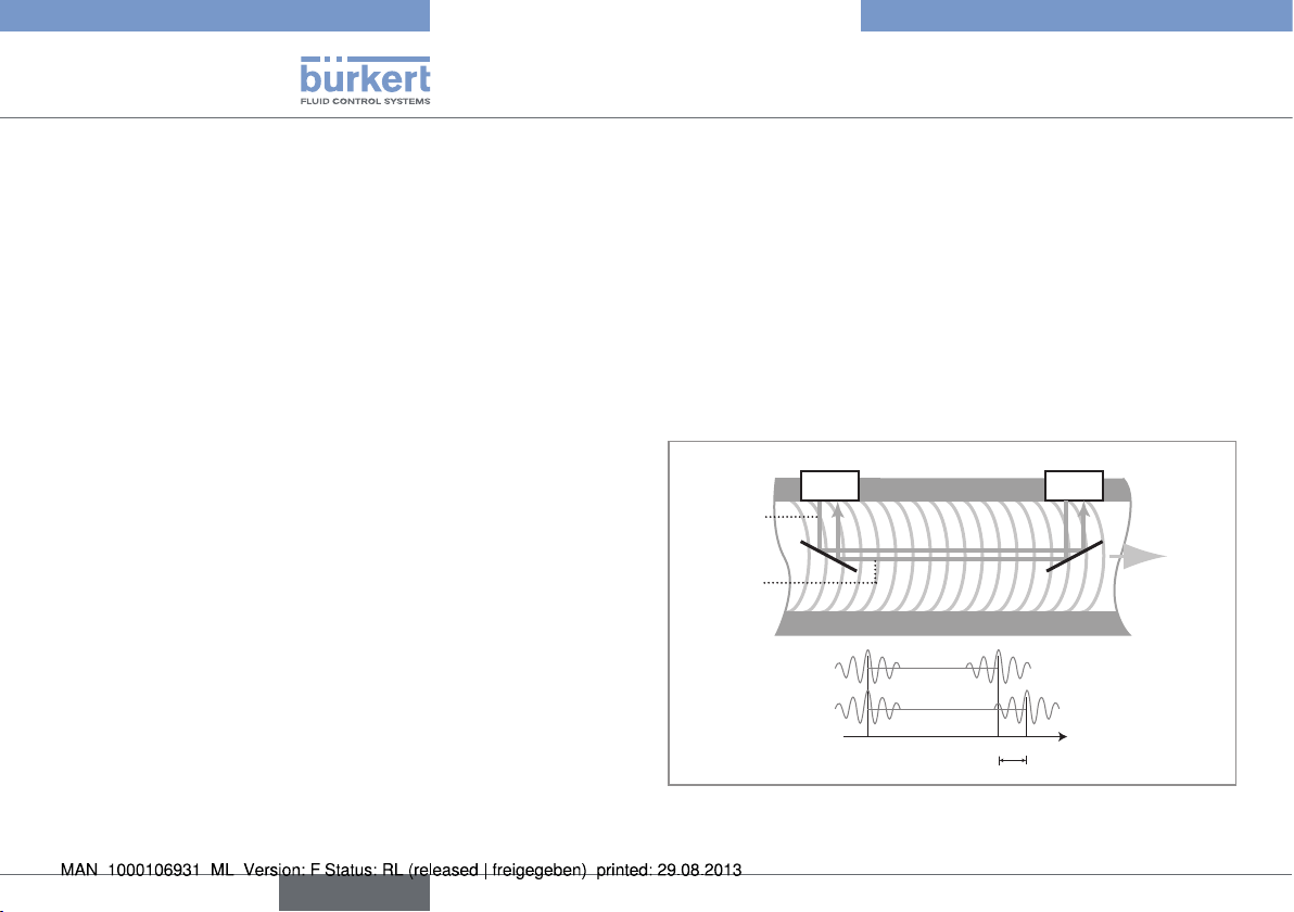
5.2.2. Measuring item and principle
The 8081 flow meter is based on the transit time method. This consists in measuring the transit times of the sound from emitter 1 to
receiver 2 and from emitter 2 to receiver 1 and subsequently comparing both values. The calculated transist time difference is directly
proportional to the flow speed of the fluid.
emitter-receiver emitter-receiver
ultrasonic
wave 1
ultrasonic
wave 2
The electronic module then delivers a pulse signal proportional to
the volume or an industry-standard 4-20mA signal, proportional to
1 2
t
0
t
t
1
2
∆t
Direction
of flow of
the fluid
8
english
Page 9

Type 8081
1
3 4 2
Description
the flow rate or to the temperature.
5.3. Description of the name plate
1. Measured quantity, type of flow meter
2. Supply voltage
3. Measuring principle
4. Nominal flow rate
5. Output data
6. Process connection
7. Flow rate range
8. Manufacturing code
9. Serial number
10. Order code
11. Materials: housing, seal
FLOW8081 ULTRAS QN2.5
NPN/PNP : 0,7A - 36VDC
12-36 VDC 4-20mA G1
MSEPDMFKM
S/N 1000
Made in France
00559869
0,16-82L/MIN
W41LP
9 11 710
5
6
8
english
9
Page 10

5.4. Order codes
Type 8081
Description
QN
0,6 15
1,5 15
10
DN
0.06 to
20 l/min
0,1 to
50 l/min
Flow rate range
Connection
G 3/4'' external thread
NPT 3/4'' external thread
G 3/4'' external thread
NPT 3/4'' external thread
english
Outputs
Pulse, NPN 560131
Pulse, PNP +
4-20 mA, sourcing
mode
Pulse, NPN 560612
Pulse, PNP +
4-20 mA, sourcing
Pulse, NPN 559865
Pulse, PNP +
4-20 mA, sourcing
mode
Pulse, NPN 560613
Pulse, PNP +
4-20 mA, sourcing
mode
Ordering codes
560113
560617
559868
560618
QN
2,5 20
3,5 25
DN
0,16 to
82 l/min
0,6 to
116 l/min
Flow rate range
G 1'' external
thread
NPT 1'' external thread
G 1 1/4'' external thread
NPT 1 1/4''
external
thread
Connection
Pulse, NPN 559866
Pulse, PNP +
4-20 mA, sourcing
mode
Pulse, NPN 560614
Pulse, PNP +
4-20 mA, sourcing
mode
Pulse, NPN 559867
Pulse, PNP +
4-20 mA, sourcing
mode
Pulse, NPN 560615
Pulse, PNP +
4-20 mA, sourcing
mode
Outputs
Ordering codes
559869
560619
559870
560620
Page 11

QN
6 25
DN
1 to
200 l/min
Flow rate range
Type 8081
Technical data
Connection
G 1 1/4'' external thread
NPT 1 1/4''
external
thread
Outputs
Pulse, NPN 560132
Pulse, PNP +
4-20 mA, sourcing
mode
Pulse, NPN 560616
Pulse, PNP +
4-20 mA, sourcing
mode
Ordering codes
560114
560621
6. TECHNICAL DATA
6.1. Conditions of use
Ambient temperature: +5 to +55 °C
Storage temperature: +5 to +55 °C
Air humidity: < 80%, not condensated
Protection rating: IP65 with cable plug plugged-in and
tightened
6.2. Conformity to standards and
directives
EMC: EN61000-6-3, 61000-6-2
Vibration: EN 60068-2-6
Shock: EN 60068-2-27
Pressure: complying with article 3 of §3 from 97/23/CE directive
For the 97/23/CE pressure directive, the device can only be used in
the following cases (depending on max. pressure, pipe diameter and
fluid)
Type of fluid Conditions
Fluid group 1, §1.3.a Forbidden
Fluid group 2, §1.3.a
Fluid group 1, §1.3.b Forbidden
Fluid group 2, §1.3.b Allowed
Allowed (PN*DN
english
≤ 1000)
11
Page 12

Type 8081
Technical data
6.3. General technical data
6.3.1. Mechanical data
Item Material
Housing, cover PPS
Seal in contact with
the environment
M12 connector
Fitting
Measuring tube PES
Seal in contact with
the fluid
Silicone
PA
Brass
EPDM, FKM
Dimensions [mm]
B
L5
Hh
A
L1
L3
L4
L2
DN A B H h L1 L2 L3 L4 L5
15 G or NPT 3/4'' 65.5 76.5 14.5 110 90 58 6.5 19.5
20 G or NPT 1'' 65.5 79 18 130 90 58 6.5 19.5
25 G or NPT 1 1/4'' 65.5 83.5 23 260 90 58 6.5 19.5
12
english
Page 13

Type 8081
Technical data
6.3.2. General data
Pipe diameter DN15 to DN25
Type of fluid water (or neutral liquids on request)
Fluid temperature 5 to 90°C
Fluid pressure PN 16
Measuring range 0.06 to 200 l/min
Accuracy (see curves on
next page)
Repeatability 1% of measured value
Measuring element 2 ultrasound emitter-receiver cells
* Full Scale, see measuring range on the diagram of measurement accuracy.
1)
Reference conditions: fluid = water, water and ambient temperatures = 20°C
± (0.01 % of Full Scale* + 2% of
measured value)
1)
Measurement accuracy
Max. measurement
deviation in %
10
8
6
4
2
0
-2
-4
-6
-8
-10
0,1 1 10 100 1000
max DN15
max DN20
max DN25
Flow rate in l/min
english
13
Page 14

Type 8081
Technical data
6.3.3. Electrical characteristics
Supply voltage (V+) 12-36 VDC
Current consumption • Own consumption: < 4 mA
• Consumption with load: < 1A
Pulse output
(transistor)
• version without
current output
• NPN as default setting; (PNP on
request), open collector, 5 mA min.,
700 mA max., NPN output: 0,2-36 VDC
• version with cur-
rent output
• PNP as default setting; (on request:
NPN for the pulse output and sinking mode for the current output), open
collector, 5 mA min., 700 mA max.,
PNP output: supply voltage (V+)
If QN=0.6 or 1.5: 1 pulse corresponds
to a volume V = 0.002 l (K factor =
500 pulse/litre)
If QN=2.5 or 3.5: 1 pulse corresponds
to a volume V = 0.005 l (K factor =
200 pulse/litre)
If QN=6: 1 pulse corresponds to
a volume V = 0.01 l (K factor =
100 pulse/litre)
Current output 4-20 mA (sourcing mode as default set-
ting; on request: sinking mode for the current output and NPN for the pulse output)
corresponding to the flow rate range of
the selected model (default setting) or to a
temperature range (on request)
max. loop resistance :
1100 W at 36 V DC
610 W at 24 V DC
100 W at 12 V DC
Protection against:
reversed polarity
voltage peaks
short-circuits
Recommended cable
type
yes
yes
yes, for the pulse output
max. cross section of 1.5 mm
2
6.3.4. Electrical connections
Flow rate meter
version
Any version female 5-pin M12 cable plug (available as an
Type of cable plug
accessory; Order code 438680)
14
english
Page 15

Type 8081
Installation and wiring
7. INSTALLATION AND WIRING
7.1. Safety instructions
DANGER
Risk of injury due to high pressure
• Cut off the pressure and depressurize the pipes before loosening
the pipes and connections.
Risk of injury due electrical discharge.
• Before starting work, make sure that you switch off the supply
voltage and secure it to prevent restarting.
• Observe all applicable accident protection and safety guidelines
for electrical equipment.
WARNING
Risk of injury due to non-conforming installation.
• The electrical and fluid installation can only be carried out by quali-
fied and skilled staff with the appropriate tools
• Install appropriate safety devices (correctly rated fuse and/or
circuit-breaker).
• Use cables with an operating temperature limit which is suitable
for your application.
• Under normal conditions of use, cables with a 0.75 mm
section should be enough to transmit the signal.
2
cross
WARNING
Risk of injury due to unintentional switch on of power supply or
uncontrolled restarting of the installation.
• Take appropriate measures to avoid any involuntary activation of
the installation.
• Guarantee a set or controlled restarting of the process subsequent
to the assembly of the device.
NOTICE
When the cover is removed, the transmitter may be damaged
through any element touching the electronics, and the tightness
of the transmitter is no longer ensured.
• Do not dismantle the device
7.2. Installation onto the pipe
DANGER
Risk of injury due to high pressure in the installation.
• Cut off the pressure and depressurize the pipes before loosening
the pipes and connections.
The 8081 ultrasonic flow rate transmitter can be fitted onto a horizontal or vertical pipe.
english
15
Page 16

Type 8081
Installation and wiring
When horizontally
Correct
Correct
Incorrect
Incorrect
mounted, the max. fluid
temperature is 90°C.
But the max. fluid temperature must be reduced to 80°C when the
electronics (black enclosure) is turned upwards.
When vertically mounted
the max. fluid temperature is also 80°C.
→ Please be careful to respect the correct direction of fluid
flow in the pipe. It is indicated with an arrow, marked on the
underside of the fitting.
It is advisable to avoid placing the 8081 transmitter near
any source of electromagnetic interference (switch, electric
motor, fluorescent lamp, ...).
Minimum upstream and downstream distances are not necessary.
The 8081 works correctly when the pipe is full and free of any air
bubbles near the transmitter. In presence of bubbles in the pipe, the
left installation no.1 should be avoided.
1 2 3 4
If the absence of any air bubbles cannot be guaranteed, the device
should then be fitted on an horizontal pipe, with the electronic enclosure facing down. Thus the bubbles will not interfere with the circulation of ultrasonic waves.
16
english
Page 17

Type 8081
Installation and wiring
NOTICE
When mounting the device on the pipe, the M12 fixed connector
may be damaged.
If the M12 fixed connector is damaged the device cannot be used
anymore.
• Please be careful not to damage the M12 fixed connector when
mounting the device on the pipe.
7.3. Electrical wiring
DANGER
Risk of injury due to electrical discharge
• Before starting work, make sure that you switch off the supply
voltage and secure it to prevent restarting.
• Do not install the cable near high voltage or high frequency cables.
• If this is unavoidable, keep to a minimum clearance of 30 cm.
• Observe all applicable accident protection and safety guidelines
for electrical equipment
• The power supply must be filtered and regulated.
→ Make sure the installation is earthed equipotentially
(power supply - 8081).
→ Connect the different earth connections of the installation to
one another in order to remove any differences in potential
which may arise between the two earth connections.
→ Connect the cable shielding to the earth. Connect the nega-
tive terminal of the power supply to the earth to remove the
effects of the common mode currents. If this connection cannot be made directly, a 100 nF/50 V capacitor can be fitted
between the negative terminal of the power supply and the
earth.
(*) If a direct earthing
connection is not possible, fit a 100 nF/50 V
capacitor between the
negative terminal of the
power supply and the
earth.
(**)
+
-
12-36VDC
(*)
english
(**) If your cable is
shielded.
17
Page 18
Type 8081
4
5
3
1
2
0 VDC
V+
(12-30 VDC)
4
5
3
1
2
0 VDC
V+
(12-30 VDC)
Installation and wiring
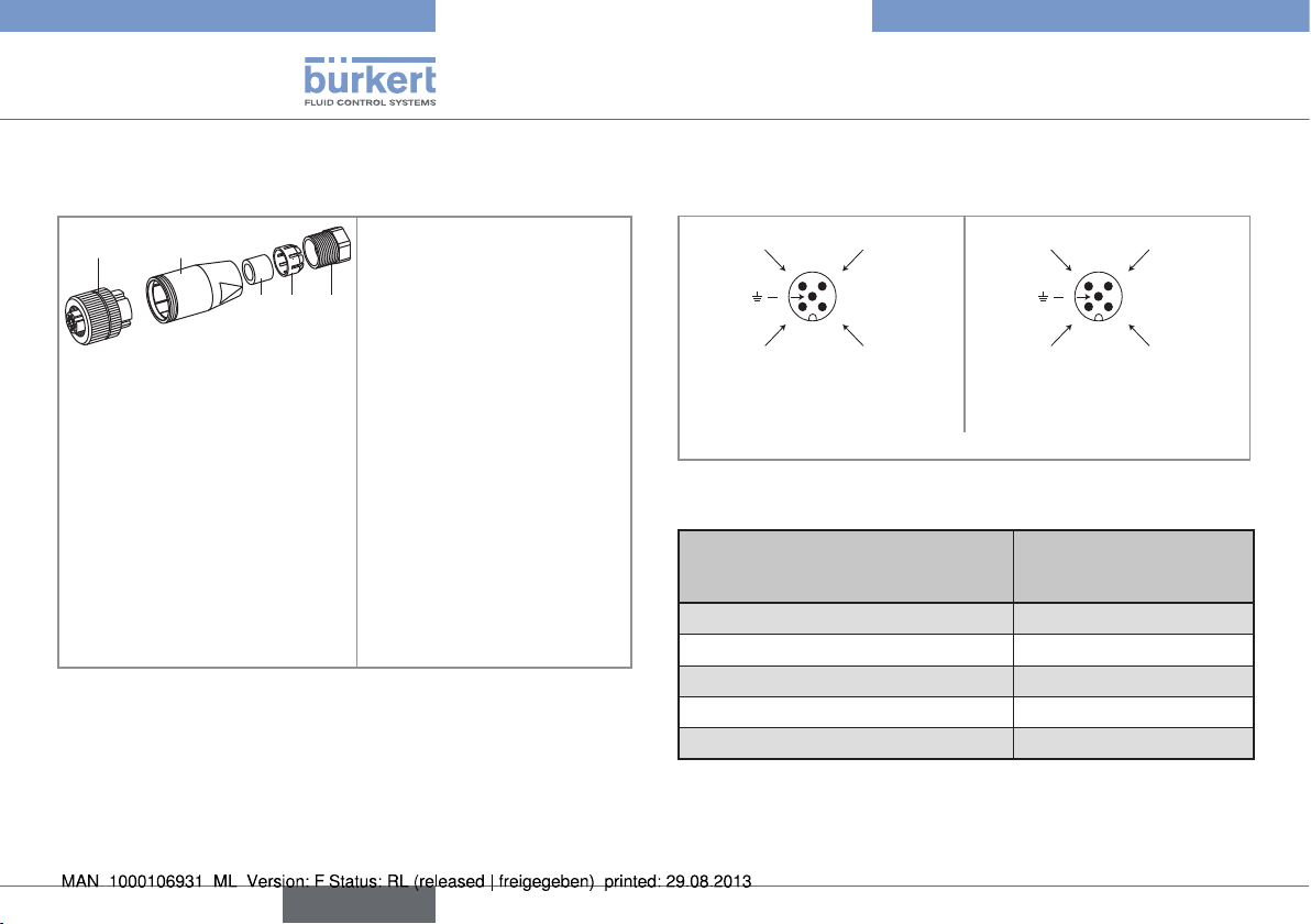
7.3.1. Assembly of the female cable plug
(order code 438680)
1 2
3 4 5
→ Fully unscrew terminal
block [1]
→ Remove body [2].
→ Unscrew clamping nut [5].
→ Pass cables through
clamping nut [5], then
through clamp ring [4]
and gasket [3], and finally
through body [2].
→ Wire terminal block [1]
(acc. to 8.3.2, 8.3.3, 8.3.4
or 8.3.5)
→ Screw terminal block [1]
onto body [2].
→ Insert gasket [3] and clamp
ring [4] into body [2].
→ Screw clamping nut [5].
18
english
7.3.2. Wiring of the 5-pin M12 fixed
connector
Not connected
(*)
Pulse output
(NPN default
setting)
(*) Functional earth connection
Wiring a version with pulse
output
Pin of M12 cable plug with a 2-m
cable available as accessory
(order code 438680)
1 brown
2 white
3 blue
4 black
5
4-20 mA
(*)
Pulse output
(PNP default
setting)
Wiring a version with pulse and
current outputs
Colour of wire
grey
Page 19

Type 8081
Installation and wiring
7.3.3. Connecting the pulse output
The pulse output is connected in NPN mode (default setting on a
version without current output) or in PNP mode (default setting on a
version with current output).
Load
white
3
blue
NPN connection
2
5
4
brown
1
grey
+ -
12-36 VDC
Load
white
2
3
4
blue
PNP connection
brown
5
1
grey
12-36 VDC
+ -
7.3.4. Only connecting the current output
The current output, where present, is connected in source mode
(default setting) or in sink mode (on request).
4-20 mA
input
+ -
2
5
brown
black
1
3
4
grey
blue
+ -
Supply
12-36 VDC
Source mode connection
(default setting)
(*) If a direct earthing connection is not possible, fit a 100 nF/50 V capacitor between the negative terminal of the power supply and the earth.
(*)
4-20 mA
input
+ -
2
5
brown
1
3
4
black
grey
blue
Sink mode connection
(on request)
+ -
Supply
12-36 VDC
(*)
english
19
Page 20

Type 8081
Commissioning
7.3.5. Connecting both the current and
pulse outputs
Load
white
2
brown
3
1
4
blue
black
+ -
4-20 mA
input
12-36 VDC
grey
(*)
+ -
Supply
PNP/sourcing mode connection
(default setting)
(*) If a direct earthing connection is not possible, fit a 100 nF/50 V capacitor
between the negative terminal of the power supply and the earth.
Load
white
2
brown
3
1
4
blue
black
+ -
4-20 mA
input
12-36 VDC
grey
+ -
(*)
Supply
NPN/sinking mode connection
(on request)
8. COMMISSIONING
8.1. Safety instructions
WARNING
Danger due to non-conforming commissioning.
Non-conforming commissioning could lead to injuries and damage
the device and its surroundings.
• Before commissioning, make sure that the staff in charge have
read and fully understood the contents of the manual.
• In particular, observe the safety recommendations and standard
operating practices.
• The device/installation must only be commissioned by suitably
trained staff.
• Protect the device against electromagnetic interference, ultraviolet rays and, when installed outdoors, the effects of the climatic
conditions.
20
english
Page 21

Type 8081
Adjustment and functions
9. ADJUSTMENT AND FUNCTIONS
9.1. Safety instructions
WARNING
Risk of injury due to non-conforming adjustment.
• The operators in charge of adjustment must have read and understood the contents of this manual.
• In particular, observe the safety recommendations and standard
operating practices.
• The device/installation must only be adjusted by suitably trained
staff.
9.2. Adjustment of the 8081
• Pulse output:
The pulse output delivers a frequency in proportion to a volume.
A pulse is generated each time a set volume passes, i.e. either
V = 0.002 litre (for a model with QN = 0.6 or 1.5) or V = 0.005 litre (for a model with QN = 2.5 or 3.5) or V = 0.01 litre (for a model with QN = 6).
• Current output:
The current output, where present, is pre-programmed on the cur-
rent range corresponding to the flow rate range (QN0.6, QN1.5,
QN2.5, QN 3.5 or QN6) of the selected 8081 model.
10. MAINTENANCE
10.1. Safety instructions
DANGER
Risk of injury due to high pressure in the installation.
• Cut off the pressure and depressurize the pipes before loosening
the pipes and connections.
Risk of injury due to electrical discharge.
• Before starting work, be sure to switch off the supply voltage and
secure it to prevent restarting.
• Observe the applicable accident prevention and safety regulations
for electrical equipment.
WARNING
Danger due to non-conforming maintenance.
• Maintenance must only be carried out by qualified and skilled staff
with the appropriate tools.
• Following maintenance, ensure a controlled restart.
english
21
Page 22

Type 8081
Packaging, transport
10.2. Cleaning
The 8081 flow meter can be cleaned with water or using a detergent
compatible with the materials it is made of.
Please feel free to contact your Bürkert supplier for any additional
information.
11. PACKAGING, TRANSPORT
NOTICE
Damage due to transport
• Transport may damage an insufficiently protected device.
• Transport the device in shock-resistant packaging and away from
humidity and dirt.
• Avoid the effects of heat and cold which could cause the storage
temperature range to be exceeded.
• Protect the electrical interfaces by using protection caps.
12. STORAGE
NOTICE
Poor storage can damage the device.
• Store the device in a dry place away from dust.
• Storage temperature: +5 to +55°C.
22
english
Page 23

Type 8081
Disposal of the product
13. DISPOSAL OF THE PRODUCT
→
Dispose of the device and its packaging in an environmentallyfriendly way.
NOTICE
Damage to the environment caused by products contaminated
by fluids.
• Keep to the existing provisions on the subject of waste disposal
and environmental protection.
Please note:
Comply with the national and/or local regulations which
concern the area of waste disposal.
english
23
Page 24

Type 8081
24
english
Page 25

Typ 8081
Wasser-Durchfluss-Transmitter Typ 8081
Inhaltsverzeichnis:
1. DIE BEDIENUNGSANLEITUNG ...............................................................5
1.1. Darstellungsmittel ..............................................................................5
2. BESTIMMUNGSGEMÄSSE VERWENDUNG ......................................6
3. GRUNDLEGENDE SICHERHEITSHINWEISE ....................................6
4. ALLGEMEINE HINWEISE .............................................................................7
4.1. Herstelleradresse und internationale Kontaktadressen 7
4.2. Gewährleistung ....................................................................................7
4.3. Informationen im Internet ...............................................................7
5. BESCHREIBUNG .............................................................................................8
5.1. Vorgesehener Einsatzbereich ......................................................8
5.2. Allgemeine Beschreibung ..............................................................8
5.2.1. Aufbau ...................................................................................... 8
5.2.2. Messelement und Messprinzip ...........................................8
5.3. Beschreibung des Typenschilds .................................................9
5.4. Bestellnummern ..................................................................................9
6. TECHNISCHE DATEN ................................................................................ 11
6.1. Betriebsbedingungen .................................................................... 11
6.2. Normenbezüge und Richtlinien ................................................ 11
6.3. Allgemeine technische Daten ................................................... 11
6.3.1. Mechanische Daten ............................................................11
6.3.2. Allgemeine Daten ................................................................12
6.3.3. Elektrische Daten ................................................................13
6.3.4. Elektrischer Anschluss .......................................................14
7. INSTALLATION ............................................................................................... 14
7.1. Sicherheitshinweise ....................................................................... 14
7.2. Installation auf Rohrleitung ........................................................15
7.3. Elektrische Installation ..................................................................16
7.3.1. Zusammenstellung der M12-Steckdose
(Bestell-Nr 438680) ...........................................................17
7.3.2. Verkabelung des M12-5pin-Steckers ............................18
7.3.3. Anschluss des Pulsausgangs ..........................................18
7.3.4. Anschluss des Stromausgangs allein .............................19
7.3.5. Anschluss des Stromausgangs und des Pul-
sausgangs .............................................................................19
8. INBETRIEBNAHME ...................................................................................... 20
deutsch
3
Page 26

8.1. Sicherheitshinweise ....................................................................... 20
9. BEDIENUNG UND FUNKTION .............................................................. 20
9.1. Sicherheitshinweise ....................................................................... 20
9.2. Bedienung des 8081 ......................................................................20
10. WARTUNG ...................................................................................................... 21
10.1. Sicherheitshinweise ....................................................................... 21
10.2. Reinigung .............................................................................................21
11. VERPACKUNG, TRANSPORT ..............................................................21
12. LAGERUNG ................................................................................................... 21
13. ENTSORGUNG ............................................................................................ 22
Typ 8081
4
deutsch
Page 27

Typ 8081
Die Bedienungsanleitung
1. DIE BEDIENUNGSANLEITUNG
Die Bedienungsanleitung beschreibt den gesamten Lebenszyklus
des Gerätes. Bewahren Sie diese Anleitung so auf, dass sie für jeden
Benutzer gut zugänglich ist und jedem neuen Eigentümer des Gerätes
wieder zur Verfügung steht.
Die Bedienungsanleitung enthält wichtige Informationen zur
Sicherheit!
Das Nichtbeachten dieser Hinweise kann zu gefährlichen Situationen führen.
• Die Bedienungsanleitung muss gelesen und verstanden werden.
1.1. Darstellungsmittel
GEFAHR!
Warnt vor einer unmittelbaren Gefahr!
• Bei Nichtbeachtung sind Tod oder schwere Verletzungen die
Folge.
WARNUNG!
Warnt vor einer möglicherweise gefährlichen Situation!
• Bei Nichtbeachtung drohen schwere Verletzungen oder Tod.
VORSICHT!
Warnt vor einer möglichen Gefährdung!
• Nichtbeachtung kann mittelschwere oder leichte Verletzungen
zur Folge haben.
HINWEIS!
Warnt vor Sachschäden!
• Bei Nichtbeachtung kann das Gerät oder die Anlage beschädigt
werden.
bezeichnet wichtige Zusatzinformationen, Tipps und Empfehlungen.
verweist auf Informationen in dieser Bedienungsanleitung
oder in anderen Dokumentationen.
→ markiert einen Arbeitsschritt, den sie ausführen müssen.
deutsch
5
Page 28

Typ 8081
Bestimmungsgemässe Verwendung
2. BESTIMMUNGSGEMÄSSE
VERWENDUNG
WARNUNG
Bei nicht bestimmungsgemäßem Einsatz des Ultraschall-Durchfluss-Transmitters können Gefahren für Personen, Anlagen in
der Umgebung und die Umwelt entstehen.
• Der Transmitter 8081 darf nur zur Durchflussmessung von Wasser
oder neutralen Flüssigkeiten eingesetzt werden.
• Vermeiden Sie wenn möglich das Gerät in der Nähe von elektromagnetischen Störungen zu installieren.
• Schützen Sie das Gerät vor U.V.-Bestrahlung und bei Außenanwendung vor Witterungseinflüssen.
• Für den Einsatz sind die in den Vertragsdokumenten und der Bedienungsanleitung spezifizierten zulässigen Daten, Betriebs- und
Einsatzbedingungen zu beachten.
• Das Gerät nur in Verbindung mit von Bürkert empfohlenen bzw.
zugelassenen Fremdgeräten und -komponenten einsetzen.
• Voraussetzungen für den sicheren und einwandfreien Betrieb sind
sachgemäßer Transport, sachgemäße Lagerung und Installation
sowie sorgfältige Bedienung und Instandhaltung.
• Setzen Sie das Gerät nur bestimmungsgemäß ein.
→ Beachten Sie bei der Ausfuhr des Gerätes gegebenenfalls be-
stehende Beschränkungen.
3. GRUNDLEGENDE
SICHERHEITSHINWEISE
Diese Sicherheitshinweise berücksichtigen keine
• Zufälligkeiten und Ereignisse, die bei Montage, Betrieb und Wartung
der Geräte auftreten können.
• ortsbezogenen Sicherheitsbestimmungen, für deren Einhaltung,
auch in Bezug auf das Montagepersonal, der Betreiber verantwortlich ist.
Gefahr durch hohen Druck!
Gefahr durch hohe Mediumstemperaturen!
Gefahr durch elektrische Spannung!
Allgemeine Gefahrensituationen
Zum Schutz vor Verletzungen ist zu beachten
• Dass die Anlage nicht unbeabsichtigt betätigt werden kann.
• Installations- und Instandhaltungsarbeiten dürfen nur von autorisiertem Fachpersonal mit geeignetem Werkzeug ausgeführt
werden.
• Nach einer Unterbrechung der elektrischen Versorgung ist ein
definierter oder kontrollierter Wiederanlauf des Prozesses zu
gewährleisten
• Das Gerät darf nur in einwandfreiem Zustand und unter Beachtung
der Bedienungsanleitung betrieben werden.
6
deutsch
Page 29

Typ 8081
Allgemeine Hinweise
4. ALLGEMEINE HINWEISE
Allgemeine Gefahrensituationen
Zum Schutz vor Verletzungen ist zu beachten
• Für die Einsatzplanung und den Betrieb des Gerätes müssen die
allgemeinen Regeln der Technik eingehalten werden.
• Den Ultraschall-Durchfluss-Transmitter Typ 8081 nicht in explosionsgefährdeten Bereichen einsetzen.
• Verwenden Sie keine Flüssigkeiten, die unvereinbar mit den Werkstoffen des Transmitters sind.
• Belasten Sie das Gehäuse nicht mechanisch (z.B. durch Ablage
von Gegenständen oder als Trittstufe).
• Nehmen Sie keine äußerlichen Veränderungen an den Gerätegehäusen vor. Gehäuseteile und Schrauben nicht lackieren.
HINWEIS!
Elektrostatisch gefährdete Bauelemente / Baugruppen
• Das Gerät enthält elektronische Bauelemente, die gegen elektrostatische Entladung (ESD) empfindlich reagieren. Berührung
mit elektrostatisch aufgeladenen Personen oder Gegenständen
gefährdet diese Bauelemente. Im schlimmsten Fall werden sie
sofort zerstört oder fallen nach der Inbetriebnahme aus.
• Beachten Sie die Anforderungen nach EN 61340 -5-1 und 5-2,
um die Möglichkeit eines Schadens durch schlagartige, elektrostatische Entladung zu minimieren bzw. zu vermeiden!
• Achten Sie ebenso darauf, dass Sie elektronische Bauelemente
nicht bei anliegender Versorgungsspannung berühren!
4.1. Herstelleradresse und
internationale Kontaktadressen
Sie können mit dem Hersteller des Gerätes unter folgender Adresse
Kontakt aufnehmen:
Bürkert SAS
Rue du Giessen
BP 21
F-67220 TRIEMBACH-AU-VAL
oder wenden Sie sich an Ihren lokal zuständigen Vertriebsmitarbeiter
von Bürkert.
Die internationalen Kontaktadressen finden Sie auf den letzten
Seiten dieser Bedienungsanleitung. Außerdem im Internet unter:
www.burkert.com
4.2. Gewährleistung
Voraussetzung für die Gewährleistung ist der bestimmungsgemäße
Gebrauch des Transmitters 8081 unter Beachtung der im vorliegenden Handbuch spezifizierten Einsatzbedingungen.
4.3. Informationen im Internet
Bedienungsanleitungen und Datenblätter zum Typ 8081 finden Sie
im Internet unter: www.buerkert.de
deutsch
7
Page 30

Typ 8081
Beschreibung
5. BESCHREIBUNG
5.1. Vorgesehener Einsatzbereich
Der Ultraschall-Durchfluss-Transmitter Typ 8081 ist zur Durchfluss-messung von Wasser bestimmt; Dieses kann auch leicht verunreinigt sein.
5.2. Allgemeine Beschreibung
5.2.1. Aufbau
Der Ultraschall-Durchfluss-Transmitter 8081 besteht aus einem
Elektronikmodul und einem Messing-Fitting mit integriertem Messrohr. In Kombination mit einem Regler und einem Regelventil lassen
sich sehr einfach Durchfluss-Regelstrecken aufbauen.
Der elektrische Anschluss erfolgt über einen M12-5Pin-Gerätestecker.
Der Transmitter ist je nach Ausführung mit den folgenden Ausgän-
gen versehen:
• einem Pulsausgang oder
• einem Pulsausgang und einem 4-20 mA-Stromausgang
Jede Ausführung ist mit fünf verschiedenen Durchflussbereichen verfügbar:
• QN 0,6-Modell DN15 : 0,06 bis 20 l/min
(Nenngröße 0,6 m
• QN 1,5-Modell DN15 : 0,1 bis 50 l/min
(Nenngröße 1,5 m
• QN 2,5-Modell DN20 : 0,16 bis 82 l/min
(Nenngröße 2,5 m
3
/h d.h. 10 l/min)
3
/h d.h. 25 l/min)
3
/h d.h. 41 l/min)
• QN 3,5-Modell DN25 : 0,6 bis 116 l/min
(Nenngröße 3,5 m
• QN 6-Modell DN25 : 1 bis 200 l/min
(Nenngröße 6 m
3
/h d.h. 58,33 l/min)
3
/h d.h. 100 l/min)
5.2.2. Messelement und Messprinzip
Der Durchflussmesser 8081 verwendet die Ultraschall-Technologie
nach dem Laufzeit-Verfahren. Hierbei wird die Zeit gemessen, die
der Schall von Sender 1 bis Empfänger 2 bzw. von Sender 2 bis
Empfänger 1 benötigt. Die Differenz der beiden Laufzeiten ist direkt
proportional zu der Fließgeschwindigkeit des Mediums.
Sender-Empfänger Sender-Empfänger
1 2
Ultraschallwelle 1
Ultraschallwelle 2
t
0
t
t
1
2
∆t
Flüssigkeit richtung
8
deutsch
Page 31

Typ 8081
1
3 4 2
Beschreibung
Das Elektronikmodul berechnet anhand der Laufzeitdifferenz die
Fließgeschwindigkeit und stellt an dem Ausgang ein durchflussproportionales Frequenzsignal zur Verfügung. Weiterhin wird über ein
4-20 mA Normsignal wahlweise der Durchfluss oder die Temperatur
ausgegeben.
5.3. Beschreibung des Typenschilds
1. Messgröße, Art des Durchflusssensors
2. Betriebsspannung
3. Messprinzip
4. Nenndurchfluss
5. Ausgang-Kenngrößen
6. Prozessanschluss
7. Durchflussbereich
8. Konstruktions-Code
9. Serien-Nummer
10. Bestell-Nummer
11. Fitting und Dichtung Werkstoff
FLOW8081 ULTRAS QN2.5
NPN/PNP : 0,7A - 36VDC
12-36 VDC 4-20mA G1
MSEPDMFKM
S/N 1000
Made in France
00559869
0,16-82L/MIN
5.4. Bestellnummern
QN DN
0,6 15
Durchflussbereich
0,06 bis
20 l/min
Leitungsanschluss
Außengewinde
G 3/4''
Außengewinde
NPT 3/4''
5
6
W41LP
9 11 710
8
Ausgänge
Puls, NPN 560131
Puls, PNP +
4-20 mA im
Quelle-Modus
Puls, NPN 560612
Puls, PNP +
4-20 mA im
Quelle-Modus
Bestell-
Nummer
560113
560617
deutsch
9
Page 32

Typ 8081
Beschreibung
QN DN
1,5 15
2,5 20
Durchflussbereich
0,1 bis
50 l/min
0,16 bis
82 l/min
Leitungsanschluss
Außengewinde
G 3/4''
Außengewinde
NPT 3/4''
Außengewinde
G 1''
Außengewinde
NPT 1''
Ausgänge
Puls, NPN 559865
Puls, PNP +
4-20 mA im
Quelle-Modus
Puls, NPN 560613
Puls, PNP +
4-20 mA im
Quelle-Modus
Puls, NPN 559866
Puls, PNP +
4-20 mA im
Quelle-Modus
Puls, NPN 560614
Puls, PNP +
4-20 mA im
Quelle-Modus
Bestell-
Nummer
559868
560618
559869
560619
QN DN
3,5 25
6 25
Durchflussbereich
0,6 bis
116 l/min
1 bis
200 l/min
Leitungsanschluss
Außengewinde
G 1 1/4''
Außengewinde
NPT 1 1/4''
Außengewinde
G 1 1/4''
Außengewinde
NPT 1 1/4''
Ausgänge
Puls, NPN 559867
Puls, PNP +
4-20 mA im
Quelle-Modus
Puls, NPN 560615
Puls, PNP +
4-20 mA im
Quelle-Modus
Puls, NPN 560132
Puls, PNP +
4-20 mA im
Quelle-Modus
Puls, NPN 560616
Puls, PNP +
4-20 mA im
Quelle-Modus
Bestell-
Nummer
559870
560620
560114
560621
10
deutsch
Page 33

Typ 8081
Technische Daten
6. TECHNISCHE DATEN
6.1. Betriebsbedingungen
Umgebungstemperatur: 5 bis +55 °C
Lagerungstemperatur: 5 bis +55 °C
Luftfeuchtigkeit: < 80%, nicht kondensiert
Schutzklasse : IP65 mit eingesteckter und angezogener
M12-Steckdose
6.2. Normenbezüge und Richtlinien
EMV: EN61000-6-3, 61000-6-2
Vibration: EN 60068-2-6
Schock: EN 60068-2-27.
Druck: gemäß Artikel 3 des §3 der Richtlinie 97/23/CE.
Für die 97/23/CE Druck-Richtlinie kann das Gerät unter den
folgenden Bedingungen verwendet werden (abhängig von
dem max. Druck, der Rohrnennweite und der Flüssigkeit).
Typ der Flüssigkeit Bedingungen
Flüssigkeitgruppe 1, §1.3.a verboten
Flüssigkeitgruppe 2, §1.3.a
Flüssigkeitgruppe 1, §1.3.b verboten
Flüssigkeitgruppe 2, §1.3.b erlaubt
erlaubt (PN*DN
≤ 1000)
6.3. Allgemeine technische Daten
6.3.1. Mechanische Daten
Teile Werkstoff
Gehäuse, Deckel PPS
Dichtung mit der Umgebung
in Kontakt gesetzt
M12-Stecker
Fitting
Messrohr PES
Dichtung mit der Flüssigkeit
in Kontakt gesetzt
Silikon
PA
Messing
EPDM, FKM
deutsch
11
Page 34

Typ 8081
Technische Daten
Abmessungen [mm]
B
Hh
A
L1
L3
L2
DN A B H h L1 L2 L3 L4 L5
15 G oder NPT 3/4 " 65.5 76.5 14.5 110 90 58 6.5 19.5
20 G oder NPT 1" 65.5 79 18 130 90 58 6.5 19.5
25 G oder NPT 1" 1/4 65.5 83.5 23 260 90 58 6.5 19.5
6.3.2. Allgemeine Daten
Rohrdurchmesser DN15 bis DN25
L5
L4
Typ der Flüssigkeit Wasser (neutrale Flüssigkeit auf An-
frage)
Mediumstemperatur 5 bis 90 °C
Mediumsdruck PN 16
Messbereich 0,06 bis 200 l/min
Genauigkeit (siehe Diagramm nächste Seite)
± (0.01% vom Messbereichende* +
2% vom Messwert)
1)
,
Wiederholbarkeit 1% vom Messwert
Messelement 2 Sender-Empfänger-Ultraschallzellen
* Messbereichende, siehe Durchflussbereich auf Genauigkeitdiagramm
1)
Unter Referenzbedingungen, d.h. Messmedium = Wasser, Umgebungs-
und Wassertemperatur = 20 °C,
12
deutsch
Page 35

Typ 8081
Technische Daten
Messgenauigkeit Diagramm
max DN15
Max. Maßabweichung in %
10
8
6
4
2
0
-2
-4
-6
-8
-10
0,1 1 10 100 1000
max DN20
Durchfluss in l/min
max DN25
6.3.3. Elektrische Daten
Versorgungs-
12-36 VDC
spannung (V+)
Stromaufnahme • Interne Stromaufnahme: < 4 mA
• Stromaufnahme mit Last: < 1A
Pulsausgang
(Transistor)
• Ausführung ohne
Stromausgang
• NPN als Grundeinstellung; (PNP
auf Anfrage), Open Kollektor, 5 mA
min., 700 mA max., NPN-Ausgang :
0,2-36 VDC
• Ausführung mit
Stromausgang
• PNP als Grundeinstellung; (auf Anfrage:
NPN für den Pulsausgang und SenkeModus für den Stromausgang), Open
Kollektor, 5 mA min., 700 mA max.,
PNP-Ausgan g: Versorgungsspannung (V+)
Bei QN=0,6 oder 1,5: 1 Puls entspricht
einer Menge V = 0,002 l (K-Faktor =
500 Puls/Liter)
Bei QN=2,5 oder 3,5: 1 Puls entspricht
einer Menge V = 0,005 l (K-Faktor =
200 Puls/Liter)
Bei QN=6: 1 Puls entspricht einer
Menge V = 0,01 l (K-Faktor = 100 Puls/
Liter)
deutsch
13
Page 36

Typ 8081
Installation
Schutz gegen :
Falschpolung
Spannungsspitzen
Kurzschluss
vorhanden
vorhanden
vorhanden, für den Pulsausgang
Stromausgang 4-20 mA (Quelle-Modus als Grundeinstel-
lung; Auf Anfrage: Senke-Modus für den
Stromausgang und NPN für den Pulsausgang) entspricht entweder dem Durchflussbereich des ausgewählten Modells
(Grundeinstellung) oder dem Temperaturbereich (auf Anfrage)
Bürde max.:
1100 W bei 36 V DC
610 W bei 24 V DC
100 W bei 12 V DC
Empfohlener Kabeltyp
1,5 mm
2
Querschnitt max.
6.3.4. Elektrischer Anschluss
Transmitter
Ausführung
Alle M12 Steckdose, 5-polig
Typ der Steckdose
(als Zubehör unter der Bestell-Nr
438680 verfügbar)
7. INSTALLATION
7.1. Sicherheitshinweise
GEFAHR!
Verletzungsgefahr durch hohen Druck in der Anlage!
• Vor dem Lösen von Leitungen und Fitting den Druck ablassen.
Verletzungsgefahr durch Stromschlag!
• Vor Eingriffen in die Anlage die Spannung abschalten und vor
Wiedereinschalten sichern!
• Die geltenden Unfallverhütungs- und Sicherheitsbestimmungen
für elektrische Geräte beachten!
WARNUNG!
Verletzungsgefahr bei unsachgemäßer Installation!
• Fluidische und elektrische Installationen dürfen nur durch autori-
siertes Fachpersonal und mit geeignetem Werkzeug durchgeführt
werden!
• Es ist ratsam, Sicherheitsvorrichtungen für die Stromversorgung
zu installieren: richtig dimensionierte Sicherung und/oder Überlastschalter.
• Nur Kabel mit einer für Ihren Prozess ausreichenden Temperatur-
beständigkeit verwenden.
• Bei normalen Betriebsbedingungen kann das Messsignal über
ein abgeschirmtes Kabel mit einem Querschnitt von 0,75 mm
übertragen werden.
2
14
deutsch
Page 37

Typ 8081
Installation
WARNUNG!
Verletzungsgefahr durch ungewolltes Einschalten der Anlage
und unkontrollierten Wiederanlauf!
• Anlage vor unbeabsichtigtem Betätigen sichern.
• Nach der Installation einen kontrollierten Wiederanlauf gewährleisten.
HINWEIS!
Wenn der Deckel entfernt ist, kann der Transmitter durch Kontakt
zwischen dem Element und der Elektronik beschädigt werden und
die Dichtheit ist dann auch nicht mehr gewährleistet.
• Das Gerät nicht auseinanderbauen.
7.2. Installation auf Rohrleitung
GEFAHR!
Verletzungsgefahr durch hohen Druck in der Anlage!
• Vor dem Lösen von Leitungen und Fitting den Druck ablassen.
Der Ultraschall-Durchfluss-Transmitter 8081 kann entweder in waagerechte oder senkrechte Rohre montiert werden.
Bei waagerechter Ein-
Richtig
Richtig
Falsch
Falsch
baulage beträgt die max.
Flüssigkeitstemperatur
90 °C.
Die max. Flüssigkeitstemperatur verringert sich auf
80 °C, wenn die Elektronik (schwarzes Gehäuse)
nach oben gedreht ist.
Bei senkrechtem Einbau
beträgt die max. Flüssigkeitstemperatur ebenfalls
80 °C.
→ Beachten Sie die Fliessrichtung der Flüssigkeit in der
Rohrleitung. Sie muss in Richtung des unter dem Fitting gezeichneten Pfeils orientiert sein.
deutsch
15
Page 38

Typ 8081
Installation
Wenn möglich ein Einbau des Transmitters 8081 in der
Nähe Quellen von elektromagnetischen Störungen (Schalter, Elektromotor, Leuchtstofflampe, ...) vermeiden.
Mindesteinlauf- und Auslauf- Strecken müssen nicht eingehalten
werden.
Der Sensor 8081 gibt genaue Messungen, wenn das Rohr am
Transmitter zu jedem Zeitpunkt vollständig gefüllt und frei von Luftblasen ist. Mit Luftblasen im Rohr ist die Position 1 zu vermeiden.
1 2 3 4
Wenn man nicht garantieren kann, dass in der Rohrleitung keine
Luftblasen sind, dann muss das Gerät - Elektronikgehäuse nach
unten - auf eine horizontale Rohrleitung montiert werden.
So stören die Luftblasen den Ultraschallwellenkreislauf nicht.
HINWEIS!
Bei der Montage des Geräts auf die Rohrleitung, kann der M12Stecker beschädigt werden.
Wenn der M12-Stecker beschädigt ist, kann das Gerät nicht mehr
verwendet werden.
• Beachten Sie die Integrität des M12-Steckers, bei der Montage
des Geräts auf die Rohrleitung.
7.3. Elektrische Installation
GEFAHR!
Verletzungsgefahr durch Stromschlag!
• Vor Eingriffen in die Anlage die Spannung abschalten und vor
Wiedereinschalten sichern!
• Das Kabel nicht in der Nähe von Hochspannungs- oder Hochfrequenzleitungen installieren.
• Wenn eine kombinierte Installation unumgänglich ist, ein Mindestabstand von 30 cm einhalten.
• Die geltenden Unfallverhütungs- und Sicherheitsbestimmungen
für elektrische Geräte beachten!
16
deutsch
Page 39

Typ 8081
Installation
• Verwenden Sie eine gefilterte und geregelte Stromversorgung.
→ Stellen Sie die Äquipotentialität der Installation sicher (Strom-
versorgung - 8081)
→ Die verschiedenen Erdungspunkte der Installation aneinander
anschließen, damit die zwischen zwei Erdungspunkten möglicherweise erzeugten Potentialdifferenzen beseitigt werden.
→ Es muss auf vorschriftsmäßige Erdung der Abschirmung des
Kabels geachtet werden. Erden Sie den negativen Anschluss der
Versorgungsquelle, um die Auswirkungen der Gleichtaktströme
zu unterdrücken. Ist eine direkte Erdung unmöglich, schließen Sie
einen 100 nF/50 V-Kondensator zwischen den negativen Anschluss der Versorgungsspannung und der Erde an.
(*) Ist keine direkte Erdung
möglich, schließen Sie einen
100 nF / 50 V -Kondensator
zwischen dem negativen Anschluss der Versorgungsquelle
und der Erde an.
(**) Bei Verwendung eines
abgeschirmten Kabels.
(**)
+
-
12-36VDC
(*)
7.3.1. Zusammenstellung der M12Steckdose (Bestell-Nr 438680)
1 2
3 4 5
→ Klemmleiste [1] aufschrau-
ben
→ Gehäuse [2] entfernen.
→ Klemmmutter [5] auf-
schrauben.
→ Kabel durch Klemmmutter
[5] dann durch Klemmring
[4] und durch Dichtungsscheibe [3] und schließlich
durch Gehäuse [2] führen.
→ Klemmleiste [1] gemäß
§ 8.3.2, 8.3.3, 8.3.4 oder
8.3.5 verkabeln
→ Klemmleiste [1] an Gehäu-
se [2] schrauben.
→ Dichtungscheibe [3] und
Klemmring [4] in Gehäuse
[2] einfügen.
→ Klemmmutter [5] fest-
schrauben.
deutsch
17
Page 40

Typ 8081
4
5
3
1
2
0 VDC
V+
(12-30 VDC)
4
5
3
1
2
0 VDC
V+
(12-30 VDC)
Installation
7.3.2. Verkabelung des M12-5pin-Steckers
Nicht belegt
(*)
Pulsausgang
(NPN als Grund-
einstellung)
(*) Funktionelle Erde
Verkabelung der
Pulsausgangsausführung
Pin-Nummer der als Zubehör verfügbaren M12-Steckdose mit 2 m
Kabel (Bestell-Nummer 438680)
1 braun
2 weiß
3 blau
4 schwarz
5
18
4-20 mA
(*)
Pulsausgang
(PNP als Grund-
Verkabelung der Puls- und
Strom-Ausgangsausführung
Farbe der Adern
grau
einstellung)
deutsch
7.3.3. Anschluss des Pulsausgangs
Der Pulsausgang kann entweder im NPN-(Grundeinstellung bei
einer Ausführung ohne Stromausgang) oder PNP-(Grundeinstellung
bei einer Ausführung mit Stromausgang) Modus angeschlossen
werden.
Last
weiß
3
blau
NPN-Anschluss
2
5
4
braun
1
grau
+ -
12-36 VDC
Last
weiß
3
blau
PNP-Anschluss
2
5
4
braun
1
grau
12-36 VDC
+ -
Page 41

Typ 8081
Installation
7.3.4. Anschluss des Stromausgangs
allein
Der Stromausgang, wenn vorhanden, kann als Quelle (Grundeinstellung) oder als Senke (auf Anfrage) angeschlossen werden.
(*)
4-20 mA
Eingang
+ -
2
3
schwarz
blau
Anschluss als Senke
(auf Anfrage)
5
braun
1
4
grau
Versorgung
12-36 VDC
(*)
+ -
4-20 mA
Eingang
+ -
2
5
braun
1
3
schwarz
4
grau
blau
+ -
Versorgung
12-36 VDC
Anschluss als Quelle
(Grundeinstellung)
(*) Ist keine direkte Erdung möglich, schließen Sie einen 100 nF / 50 V
-Kondensator zwischen dem negativen Anschluss der Versorgungsquelle
und der Erde an.
7.3.5. Anschluss des Stromausgangs
und des Pulsausgangs
Last
weiß
2
3
braun
1
4
blau
grau
schwarz
+ -
4-20 mA-
Eingang
12-36 VDC
(*)
+ -
Versorgung
Anschluss als PNP/Quelle
(Grundeinstellung)
(*) Ist keine direkte Erdung möglich, schließen Sie einen 100 nF / 50 V
-Kondensator zwischen dem negativen Anschluss der Versorgungsquelle
und der Erde an.
Last
weiß
2
3
braun
1
4
blau
schwarz
+ -
4-20 mA-
Eingang
+ -
12-36 VDC
Versorgung
Anschluss als NPN/Senke
(auf Anfrage)
grau
(*)
deutsch
19
Page 42

Typ 8081
Inbetriebnahme
8. INBETRIEBNAHME
8.1. Sicherheitshinweise
WARNUNG
Verletzungsgefahr bei unsachgemäßem Betrieb!
Nicht sachgemäßer Betrieb kann zu Verletzungen, sowie Schäden
am Gerät und seiner Umgebung führen.
• Vor der Inbetriebnahme muss gewährleistet sein, dass der Inhalt
der Bedienungsanleitung dem Bedienungspersonal bekannt ist
und vollständig verstanden wurde.
• Die Sicherheitshinweise und die bestimmungsgemäße Verwen-
dung müssen beachtet werden.
• Nur ausreichend geschultes Personal darf die Anlage/das Gerät
in Betrieb nehmen.
• Das Gerät muss vor elektromagnetischen Störungen, vor UVBestrahlung und, bei Außenanwendung, vor Witterungseinflüssen
geschützt werden.
9. BEDIENUNG UND FUNKTION
9.1. Sicherheitshinweise
WARNUNG
Verletzungsgefahr bei unsachgemäße Bedienung!
• Das Bedienungspersonal muss den Inhalt der Bedienungsanleitung kennen und verstanden haben.
• Die Sicherheitshinweise und die bestimmungsgemäße Verwendung müssen beachtet werden.
• Nur ausreichend geschultes Personal darf die Anlage/das Gerät
bedienen.
9.2. Bedienung des 8081
• Pulsausgang:
Der Pulsausgang liefert eine Frequenz, welche proportional zu einer
Menge ist.
Für jeden Durchgang ist ein Puls eines der Ausführung entsprechenden festgelegten Volumens der Flüssigkeit erzeugt, d.h.
V = 0,002 Liter bei einer Ausführung mit QN = 0,6 oder 1,5 bzw.
V = 0,005 Liter bei einer Ausführung mit QN = 2,5 oder 3,5 bzw.
V = 0,01 Liter bei einer Ausführung mit QN = 6.
• Stromausgang:
Wenn vorhanden ist der Stromausgang mit einem dem ausge-
wählten 8081 Modell entsprechenden Durchflussbereich (QN0,6;
QN1,5; QN2,5; QN3,5; QN6) voreingestellt.
20
deutsch
Page 43

Typ 8081
Wartung
10. WARTUNG
10.1. Sicherheitshinweise
GEFAHR
Verletzungsgefahr durch hohen Druck in der Anlage!
• Vor dem Lösen von Leitungen den Druck ablassen.
Verletzungsgefahr durch Stromschlag!
• Vor Eingriffen in die Anlage die Spannung abschalten und vor
Wiedereinschalten sichern!
• Die geltenden Unfallverhütungs- und Sicherheitsbestimmungen
für elektrische Geräte beachten!
WARNUNG
Gefahr durch unsachgemäße Wartungsarbeiten!
• Die Wartung darf nur autorisiertes Fachpersonal mit geeignetem
Werkzeug durchführen!
• Nach der Wartung einen kontrollierten Wiederanlauf gewährleisten.
10.2. Reinigung
Zur Reinigung des Gerätes 8081 verwendet man Wasser oder ein
für die Materialien der Fittings geeignetes Lösungsmittel.
Für weitere Auskünfte, steht Ihnen Bürkert zur Verfügung.
11. VERPACKUNG, TRANSPORT
HINWEIS!
Transportschäden
Unzureichend geschützte Geräte können durch den Transport
beschädigt werden.
• Gerät vor Nässe und Schmutz geschützt in einer stoßfesten Verpackung transportieren.
• Eine Über- bzw. Unterschreitung der zulässigen Lagertemperatur
vermeiden.
• Verschließen Sie die elektrischen Schnittstellen mit Schutzkappen.
12. LAGERUNG
HINWEIS!
Falsche Lagerung kann Schäden am Gerät verursachen.
• Lagern Sie das Gerät trocken und staubfrei!
• Lagerungstemperatur: 5 bis +55 °C
deutsch
21
Page 44

13. ENTSORGUNG
→
Entsorgen Sie das Gerät und die Verpackung umweltgerecht.
HINWEIS!
Umweltschäden durch von Medien kontaminierte Geräteteile.
• Geltenden Entsorgungsvorschriften und Umweltbestimmungen
einhalten.
Hinweis:
Beachten Sie die nationalen Abfallbeseitigungsvorschriften.
Typ 8081
Entsorgung
22
deutsch
Page 45

Typ 8081
deutsch
23
Page 46

Typ 8081
24
deutsch
Page 47

Sommaire :
Type 8081
Transmetteur de débit d'eau Type 8081
1. À PROPOS DE CE MANUEL ......................................................................5
1.1. Symboles utilisés ................................................................................5
2. UTILISATION CONFORME..........................................................................6
3. CONSIGNES DE SÉCURITÉ DE BASE ................................................6
4. INFORMATIONS GÉNÉRALES ..................................................................7
4.1. Adresse du fabricant et contacts internationaux ...............7
4.2. Conditions de garantie .....................................................................7
4.3. Informations sur internet ................................................................7
5. DESCRIPTION ...................................................................................................8
5.1. Secteur d'application ........................................................................8
5.2. Description générale .........................................................................8
5.2.1. Construction ........................................................................... 8
5.2.2. Élément et principe de mesure .......................................... 8
5.3. Description de l'étiquette d'identification ...............................9
5.4. Références de commande .......................................................... 10
6. CARACTÉRISTIQUES TECHNIQUES .................................................11
6.1. Conditions d'utilisation ..................................................................11
6.2. Conformité aux normes et directives .....................................11
6.3. Caractéristiques techniques générales ............................... 12
6.3.1. Caractéristiques mécaniques ...........................................12
6.3.2. Caractéristiques générales ...............................................13
6.3.3. Caractéristiques électriques .............................................14
6.3.4. Raccordements électriques ..............................................14
7. INSTALLATION ET CÂBLAGE................................................................. 15
7.1. Consignes de sécurité .................................................................. 15
7.2. Installation sur la canalisation .................................................. 15
7.3. Câblage électrique .......................................................................... 17
7.3.1. Assembler le connecteur femelle M12 (réfé-
rence de commande 438680) .........................................18
7.3.2. Câblage de l'embase M12 mâle ......................................18
7.3.3. Raccordement de la sortie impulsion .............................19
7.3.4. Raccordement de la sortie courant seule ......................19
7.3.5. Raccordement de la sortie courant et de la
sortie impulsion ....................................................................20
8. MISE EN SERVICE ....................................................................................... 20
français
3
Page 48

8.1. Consignes de sécurité .................................................................. 20
9. RÉGLAGE ET FONCTIONNALITÉS ......................................................21
9.1. Consignes de sécurité .................................................................. 21
9.2. Réglage du 8081 .............................................................................. 21
10. MAINTENANCE ...........................................................................................21
10.1. Consignes de sécurité .................................................................. 21
10.2. Entretien ................................................................................................22
11. EMBALLAGE, TRANSPORT .................................................................. 22
12. STOCKAGE ................................................................................................... 22
13. ÉLIMINATION DE L'APPAREIL .............................................................22
Type 8081
Table des matières
4
français
Page 49

Type 8081
À propos de ce manuel
1. À PROPOS DE CE MANUEL
Ce manuel décrit le cycle de vie complet de l'appareil. Conservez-le
de sorte qu'il soit accessible à tout utilisateur et à disposition de tout
nouveau propriétaire.
Ce manuel contient des informations importantes relatives à
la sécurité.
Le non-respect de ces consignes peut entraîner des situations
dangereuses.
• Ce manuel doit être lu et compris.
1.1. Symboles utilisés
DANGER
Met en garde contre un danger imminent.
• Son non-respect peut entraîner la mort ou de graves blessures.
AVERTISSEMENT
Met en garde contre une situation éventuellement dangereuse.
• Son non-respect peut entraîner de graves blessures, voire la
mort.
ATTENTION
Met en garde contre un risque éventuel.
• Son non-respect peut entraîner des blessures légères ou de
gravité moyenne.
REMARQUE
Met en garde contre des dommages matériels.
• Son non-respect peut entraîner des dommages sur l‘appareil ou
l‘installation.
désigne des informations supplémentaires, des conseils ou
des recommandations importants.
renvoie à des informations contenues dans ce manuel ou
dans d‘autres documents.
→ indique une opération à effectuer.
français
5
Page 50

Type 8081
Utilisation conforme
2. UTILISATION CONFORME
L‘utilisation non conforme du transmetteur de débit à ultrasons
peut présenter des dangers pour les personnes, les installations
proches et l‘environnement.
• Le transmetteur 8081 est exclusivement destiné à la mesure du
débit dans de l'eau ou des liquides neutres.
• Si possible, éviter de placer cet appareil à proximité de perturbations électromagnétiques,
• Cet appareil doit être protégé contre les rayons ultraviolets et,
lorsqu'il est installé à l'extérieur, des effets des conditions climatiques.
• Cet appareil doit être utilisé conformément aux caractéristiques et
conditions de mise en service et d'utilisation indiquées dans les
documents contractuels et dans le manuel utilisateur.
• L'appareil ne peut être utilisé qu'en association avec les appareils
et composants recommandés et/ou homologués par Bürkert.
• L'utilisation en toute sécurité et sans problème de l'appareil repose
sur un transport, un stockage et une installation corrects ainsi que
sur une utilisation et une maintenance effectuées avec soin.
• Veiller à toujours utiliser cet appareil de façon conforme.
→ Respecter les restrictions éventuelles lorsque l'appareil est
exporté.
3. CONSIGNES DE SÉCURITÉ DE
BASE
Ces consignes de sécurité ne tiennent pas compte :
• des imprévus pouvant survenir lors du montage, de l'utilisation et de
l'entretien des appareils.
• des prescriptions de sécurité locales que l'exploitant est tenu de
faire respecter par le personnel chargé du montage.
Danger dû à la haute pression.
Danger dû à des températures élevées du fluide.
Danger dû à la tension électrique.
Situations dangereuses diverses.
Pour éviter toute blessure, veiller à :
• empêcher toute mise sous tension.
• ce que les travaux d'installation et de maintenance soient effectués par du personnel qualifié et habilité disposant des outils
appropriés.
• garantir un redémarrage défini et contrôlé du process, après une
coupure de l'alimentation électrique
• n'utiliser l'appareil qu'en parfait état et en tenant compte des
indications du manuel utilisateur.
6
français
Page 51

Type 8081
Informations générales
4. INFORMATIONS GÉNÉRALES
Situations dangereuses diverses.
Pour éviter toute blessure, veiller à :
• respecter les règles générales de la technique lors de la planification et de l'utilisation de l'appareil.
• ne pas utiliser le transmetteur de débit à ultrasons type 8081 dans
une atmosphère explosible.
• ne pas utiliser de fluide incompatible avec les matériaux composant
le transmetteur.
• ne pas soumettre l'appareil à des charges mécaniques (par ex.
en y déposant des objets ou en l'utilisant comme marchepied).
• n'apporter aucune modification extérieure sur l'appareil. Ne laquer
aucune pièce de l'appareil.
REMARQUE
Éléments / Composants sensibles aux décharges électrostatiques
• Cet appareil contient des composants électroniques sensibles
aux décharges électrostatiques. Ils peuvent être endommagés
lorsqu'ils sont touchés par une personne ou un objet chargé
électro-statiquement. Dans le pire des cas, ils sont détruits instantanément ou tombent en panne sitôt effectuée la mise en route.
• Pour réduire au minimum voire éviter tout dommage dû à une
décharge électrostatique, prenez toutes les précautions décrites
dans les normes EN 61340-5-1 et 5-2.
• Veiller également à ne pas toucher les composants électriques
sous tension.
4.1. Adresse du fabricant et contacts
internationaux
Le fabricant de l'appareil peut être contacté à l‘adresse suivante :
Bürkert SAS
Rue du Giessen
BP 21
F-67220 TRIEMBACH-AU-VAL
Vous pouvez aussi contacter votre revendeur Bürkert.
Les adresses des filiales internationales se trouvent sur les dernières
pages du manuel. Elles sont également disponibles sur internet
sous : www.burkert.com
4.2. Conditions de garantie
La condition pour bénéficier de la garantie légale est l’utilisation
conforme du transmetteur de débit type 8081 dans le respect des
conditions d’utilisation spécifiées dans le présent manuel utilisateur.
4.3. Informations sur internet
Retrouvez sur internet les manuels utilisateur et les fiches techniques relatifs au type 8081 sous : www.burkert.fr
français
7
Page 52

Type 8081
Description
5. DESCRIPTION
5.1. Secteur d'application
Le transmetteur de débit à ultrasons type 8081 est destiné à la
mesure du débit d'eau, pouvant être légèrement chargée.
5.2. Description générale
5.2.1. Construction
Le transmetteur de débit à ultrasons 8081 se compose d‘un module
électronique et d‘un raccord en laiton avec tube de mesure intégré.
Associé à un régulateur et une vanne de commande, il permet d‘établir une boucle de régulation de débit.
Le raccordement électrique s‘effectue via une embase M12 mâle, 5
broches.
Le transmetteur est pourvu, suivant la version :
• d'une sortie impulsion ou
• d'une sortie impulsion et d'une sortie courant 4-20 mA
Chaque version est disponible pour 5 plages de débit différentes :
• modèle QN 0,6 DN15 : 0,06 à 20 l/min
(débit nominal 0,6 m
• modèle QN 1,5 DN15 : 0,1 à 50 l/min
(débit nominal 1,5 m
• modèle QN 2,5 DN20 : 0,16 à 82 l/min
(débit nominal 2,5 m
3
/h soit 10 l/min)
3
/h soit 25 l/min)
3
/h soit 41 l/min)
• modèle QN 3,5 DN25 : 0,6 à 116 l/min
(débit nominal 3,5 m
• modèle QN 6 DN25 : 1 à 200 l/min
(débit nominal 6 m
3
/h soit 58 l/min)
3
/h soit 100 l/min)
5.2.2. Élément et principe de mesure
Le débitmètre 8081 utilise la méthode de temps de transit. Celle-ci
consiste à mesurer les temps de propagation d'ondes ultrasonores
de l'émetteur 1 vers le récepteur 2 et de l'émetteur 2 vers le récepteur 1 puis de comparer les 2 valeurs. La différence de temps de
transit ainsi calculée est directement proportionnelle à la vitesse du
fluide.
Emetteur-récepteur Emetteur-récepteur
1 2
Onde ultrasonore 1
Onde ultrasonore 2
t
0
t
t
1
2
∆t
Sens de
circulation
du fluide
8
français
Page 53

Type 8081
1
3 4 2
Description
Le module électronique délivre ensuite un signal impulsionnel proportionnel au volume ou un signal normalisé 4-20mA, proportionnel
au débit ou à la température.
5.3. Description de l'étiquette
d'identification
FLOW8081 ULTRAS QN2.5
NPN/PNP : 0,7A - 36VDC
12-36 VDC 4-20mA G1
MSEPDMFKM
S/N 1000
Made in France
00559869
0,16-82L/MIN
W41LP
9 11 710
8
5
6
1. Grandeur mesurée, type de débitmètre
2. Tension d'alimentation
3. Principe de mesure
4. Débit nominal
5. Sortie
6. Raccordement process
7. Plage de débit
8. Code de fabrication
9. Numéro de série
10. Référence de commande
11. Matériaux corps, joint
français
9
Page 54

5.4. Références de commande
QN
DN
0,6 15
1,5 15
0,06 à
20 l/min
0,1 à
50 l/min
Plage de débit
Fileté G 3/4''
Fileté NPT 3/4''
Fileté G 3/4''
Fileté NPT 3/4''
Raccordement
Impulsion, NPN 560131
Impulsion, PNP +
4-20 mA, source
Impulsion, NPN 560612
Impulsion, PNP +
4-20 mA, source
Impulsion, NPN 559865
Impulsion, PNP +
4-20 mA, source
Impulsion, NPN 560613
Impulsion, PNP +
4-20 mA, source
Sorties
Référence de
560113
560617
559868
560618
commande
2,5 20
3,5 25
QN
DN
0,16 à
82 l/min
0,6 à
116 l/min
Type 8081
Description
Plage de débit
Fileté G 1''
Fileté NPT 1''
Fileté G 1 1/4''
Fileté
NPT 1 1/4''
Raccordement
Impulsion, NPN 559866
Impulsion, PNP +
4-20 mA, source
Impulsion, NPN 560614
Impulsion, PNP +
4-20 mA, source
Impulsion, NPN 559867
Impulsion, PNP +
4-20 mA, source
Impulsion, NPN 560615
Impulsion, PNP +
4-20 mA, source
Sorties
Référence de
559869
560619
559870
560620
commande
10
français
Page 55

QN
6 25
Type 8081
Caractéristiques techniques
DN
Plage de débit
1 à
200 l/min
Raccordement
Fileté G 1 1/4''
Fileté
NPT 1 1/4''
Impulsion, NPN 560132
Impulsion, PNP +
4-20 mA, source
Impulsion, NPN 560616
Impulsion, PNP +
4-20 mA, source
Sorties
Référence de
560114
560621
6. CARACTÉRISTIQUES TECHNIQUES
6.1. Conditions d'utilisation
commande
Température ambiante : 5 à +55 °C
Température de stockage : 5 à +55 °C
Humidité de l'air : < 80%, non condensée
Indice de protection : IP65 avec connecteur femelle enfiché et
serré
6.2. Conformité aux normes et directives
CEM : EN61000-6-3, 61000-6-2
Tenue aux vibrations : EN 60068-2-6
Tenue aux chocs : EN 60068-2-27.
Pression: conforme à l'article 3 du §3 de la directive 97/23/CE.
Pour la directive pression 97/23/CE, le produit ne peut être
utilisé que dans les cas suivants (en fonction de la pression
max, du DN de la conduite et du fluide)
français
Type du fluide Conditions
Fluide groupe 1, §1.3.a Interdit
Fluide groupe 2, §1.3.a
Fluide groupe 1, §1.3.b Interdit
Fluide groupe 2, §1.3.b Permis
Permis (PN*DN
≤ 1000)
11
Page 56

Type 8081
Caractéristiques techniques
6.3. Caractéristiques techniques
générales
6.3.1. Caractéristiques mécaniques
Élément Matériau
Boîtier, couvercle PPS
Joint en contact avec
l'environnement
Connecteur M12
Raccord
Tube de mesure PES
Joint en contact avec
le fluide
Silicone
PA
Laiton
EPDM, FKM
Dimensions [mm]
B
L5
Hh
A
L1
L3
L4
L2
DN A B H h L1 L2 L3 L4 L5
15 G ou NPT 3/4'' 65,5 76,5 14,5 110 90 58 6,5 19,5
20 G ou NPT 1'' 65,5 79 18 130 90 58 6,5 19,5
25 G ou NPT 1 1/4'' 65,5 83.5 23 260 90 58 6,5 19,5
12
français
Page 57

Type 8081
Caractéristiques techniques
6.3.2. Caractéristiques générales
Diamètre des conduites DN15 à DN25
Type du fluide Eau (liquides neutres sur demande)
Température du fluide 5 à 90 °C
Pression du fluide PN 16
Plage de mesure 0,06 à 200 l/min
Précision (voir courbes
page suivante)
Répétabilité 1% de la valeur mesurée
Élément de mesure 2 cellules émettrices-réceptrices à
* Pleine échelle, cf. étendue des mesures sur le diagramme de précision de
la mesure
1)
Dans les conditions de référence, à savoir : fluide = eau, température
ambiante et de l'eau = 20 °C,
± (0.01 % de la Pleine échelle* + 2%
de la valeur mesurée)
1)
ultrasons
Précision de la mesure
Ecart de mesure
maximum en %
10
8
6
4
2
0
-2
-4
-6
-8
-10
0,1 1 10 100 1000
max DN15
max DN20
max DN25
Débit en l/min
français
13
Page 58

Type 8081
Caractéristiques techniques
6.3.3. Caractéristiques électriques
Tension d'alimentation (V+)
Consommation en
courant
Sortie impulsion
(transistor)
• version sans sortie
courant
• version avec sortie
courant
12-36 VDC
• Consommation propre : < 4 mA
• Consommation avec charge : < 1A
• NPN par défaut ; (PNP sur demande),
collecteur ouvert, 5 mA min.,
700 mA max., sortie NPN : 0,2-36 VDC
• PNP par défaut ; (sur demande : NPN
pour la sortie impulsion et mode puits
pour la sortie courant), collecteur ouvert,
5 mA min., 700 mA max., sortie PNP :
tension d’alimentation (V+)
Pour QN=0,6 ou 1,5 : 1 impulsion correspond à un volume = 0,002 l (Facteur
K = 500 impulsions/litre)
Pour QN=2,5 ou 3,5 : 1 impulsion correspond à un volume = 0,005 l (Facteur
K = 200 impulsions/litre)
Pour QN=6 : 1 impulsion correspond à
un volume = 0,01 l (Facteur K = 100 impulsions/litre)
Protection contre :
l'inversion de polarité
les pics de tension
les courts-circuits
oui
oui
oui, pour la sortie impulsion
Sortie courant 4-20 mA (mode source par défaut ; sur
demande : mode puits pour la sortie courant et mode NPN pour la sortie transistor).
La plage 4-20 mA correspond à la plage
de débit du modèle sélectionné (par défaut) ou à une plage de température (sur
demande)
Résistance de boucle max. :
1100 W à 36 V DC
610 W à 24 V DC
100 W à 12 V DC
Type de câble
recommandé
section max. de 1,5 mm
2
6.3.4. Raccordements électriques
Version du
débitmètre
Toutes connecteur femelle M12, 5 broches
Type de connecteur femelle
(disponible en accessoire ; référence de
commande : 438680)
14
français
Page 59

Type 8081
Installation et câblage
7. INSTALLATION ET CÂBLAGE
7.1. Consignes de sécurité
DANGER
Risque de blessure dû à la présence de haute pression dans
l'installation.
• Couper la pression et dépressuriser les conduites avant de desserrer les conduites et les raccords.
Risque de blessure par décharge électrique.
• Couper l'alimentation électrique avant d'intervenir sur l'installation
et s'assurer qu'elle reste coupée.
• Respecter les règles en vigueur en matière de prévention des
accidents et de sécurité relatives aux appareils électriques.
AVERTISSEMENT
Risque de blessure dû à une installation non conforme.
• L'installation électrique et fluidique ne peut être effectuée que par
du personnel habilité et qualifié, disposant des outils appropriés
• Utiliser impérativement les dispositifs de sécurité adaptés (fusible
correctement dimensionné et/ou coupe-circuit)
• Utiliser des câbles ayant une température limite de fonctionnement
adaptée à votre application.
• Dans des conditions normales d’utilisation, du câble de section
0,75 mm
2
suffit à la transmission du signal.
AVERTISSEMENT
Risque de blessure dû à une mise sous tension involontaire de
l'installation et un redémarrage incontrôlé.
• Protéger l'installation contre toute mise sous tension involontaire.
• Garantir un redémarrage contrôlé de l'installation, après montage
de l'appareil.
REMARQUE
Lorsque le couvercle est retiré, le transmetteur risque d'être
endommagé si un élément entre en contact avec l'électronique
et son étanchéité ne sera pas assurée.
• Ne pas démonter l'appareil
7.2. Installation sur la canalisation
DANGER
Risque de blessure dû à la présence de haute pression dans
l'installation.
• Couper la pression et dépressuriser les conduites avant de desserrer les conduites et les raccords.
Le transmetteur de débit à ultrasons 8081 peut être installé sur une
conduite horizontale ou verticale.
français
15
Page 60

Type 8081
Installation et câblage
En montage horizontal,
Correct
Correct
Incorrect
Incorrect
la température du fluide
max. est de 90 °C.
Mais, la température max.
du fluide doit être réduite
à 80 °C lorsque le module électronique (boîtier
noir) est positionné vers
le haut.
En montage vertical, la
température du fluide
max. est également de
80 °C.
→ Veiller à respecter le sens du passage du fluide dans la
conduite. Il doit être identique au sens de la flèche, marquée
sur le dessous du raccord.
Par contre, il convient d'éviter de placer le transmetteur
8081 à proximité de toute source de perturbations électromagnétiques (commutateur, moteur électrique, lampe
fluorescente, ...).
Des distances amont et aval minimales ne sont pas nécessaires.
Le 8081 fonctionne correctement lorsque la canalisation est remplie
et exempte de bulles d'air à proximité du transmetteur. En présence
de bulles dans la canalisation, la position 1 est à proscrire.
1 2 3 4
Si l'absence de bulles ne peut pas être garantie, l'appareil doit être
monté sur une canalisation horizontale, module électronique vers le
bas. Ainsi, les bulles ne perturberont pas la circulation des ondes
ultrasonores.
REMARQUE
Lors du montage de l'appareil sur la conduite, l'embase M12
peut être endommagée.
• Veiller à ne pas endommager l'embase M12, lors du montage de
l'appareil sur la conduite.
16
français
Page 61

Type 8081
Installation et câblage
7.3. Câblage électrique
DANGER
Risque de blessure par décharge électrique.
• Couper l'alimentation électrique avant d'intervenir sur l'installation
et s'assurer qu'elle reste coupée.
• Ne pas installer le câble à proximité de câbles haute tension ou
haute fréquence.
• Si une pose contiguë est inévitable, respecter une distance minimale de 30 cm.
• Respecter les règles en vigueur en matière de prévention des
accidents et de sécurité relatives aux appareils électriques.
L’alimentation doit être filtrée et régulée.
→ Assurer l’équipotentialité de l’installation (alimentation - 8081) :
→ Raccorder les différentes terres de l’installation les unes aux
autres afin de supprimer les différences de potentiel pouvant
se créer entre deux terres.
→ Relier correctement le blindage du câble à la terre.
Raccorder la borne négative de l’alimentation à la terre pour
supprimer les effets des courants de mode commun. Si cette
liaison n’est pas réalisable directement, un condensateur de
100 nF/50 V peut être branché entre la borne négative de
l'alimentation et la terre.
(**)
+
-
12-36VDC
(*)
(*) Si une mise à la terre
directe est impossible,
brancher un condensateur de 100 nF/50 V entre la borne négative de
l'alimentation et la terre.
(**) Si votre câble est
blindé.
français
17
Page 62

Type 8081
4
5
3
1
2
0 VDC
V+
(12-30 VDC)
4
5
3
1
2
0 VDC
V+
(12-30 VDC)
Installation et câblage
7.3.1. Assembler le connecteur femelle
M12 (référence de commande
438680)
1 2
3 4 5
→ Dévisser complètement le
bornier [1]
→ Séparer le corps [2].
→ Dévisser l'écrou de serrage
[5].
→ Passer les câbles dans
l'écrou de serrage [5],
puis dans l'anneau de
serrage [4] et la rondelle
d'étanchéité [3], et enfin
dans le corps [2].
→ Câbler le bornier [1] (voir
8.3.2, 8.3.3, 8.3.4 ou
8.3.5)
→ Visser le bornier [1] sur le
corps [2].
→ Insérer la rondelle
d'étanchéité [3] et l'anneau
de serrage [4] dans le
corps [2].
→ Visser l'écrou de serrage
[5].
18
7.3.2. Câblage de l'embase M12 mâle
→ Dévisser le capuchon de protection de l'embase
Non connecté
(*)
Sortie impulsion
(NPN par défaut)
(*) Terre fonctionnelle
Câblage d'une version avec
sortie impulsion
Broche du connecteur M12 avec
câble 2 m disponible en accessoire (réf. de commande 438680)
1 brun
2 blanc
3 bleu
4 noir
5
français
4-20 mA
(*)
Sortie impulsion
(PNP par défaut)
Câblage d'une version avec
sorties impulsion et courant
Couleur du conducteur
gris
Page 63

Type 8081
Installation et câblage
7.3.3. Raccordement de la sortie
impulsion
La sortie impulsion se raccorde en mode NPN (par défaut sur une
version sans sortie courant) ou en mode PNP (par défaut sur une
version avec sortie courant).
Charge
blanc
2
3
4
5
bleu
Raccordement NPN
brun
1
gris
12-36 VDC
+ -
Charge
blanc
2
5
3
4
1
bleu
Raccordement PNP
brun
gris
+ -
12-36 VDC
7.3.4. Raccordement de la sortie courant
seule
La sortie courant, si elle existe, se raccorde en mode source (par
défaut) ou en mode puits (sur demande).
Entrée
4-20 mA
+ -
2
5
brun
noir
1
3
4
gris
bleu
+ -
Alimentation
12-36 VDC
Raccordement en mode source
(par défaut)
(*) Si une mise à la terre directe est impossible, brancher un condensateur
de 100 nF/50 V entre la borne négative de l'alimentation et la terre.
Entrée
4-20 mA
+ -
2
5
3
4
noir
bleu
(*)
Raccordement en mode puits
(sur demande)
brun
1
gris
+ -
Alimentation
12-36 VDC
(*)
français
19
Page 64

Type 8081
Mise en service
7.3.5. Raccordement de la sortie courant
et de la sortie impulsion
Charge
blanc
2
brun
3
1
4
bleu
noir
Entrée
4-20 mA
+ -
12-36 VDC
gris
(*)
+ -
Alimentation
Raccordement en mode
PNP/source (par défaut)
(*) Si une mise à la terre directe est impossible, brancher un condensateur
de 100 nF/50 V entre la borne négative de l'alimentation et la terre.
Charge
blanc
2
brun
3
1
4
bleu
noir
+ -
Entrée
4-20 mA
+ -
12-36 VDC
Alimentation
Raccordement en mode
NPN/puits (sur demande)
gris
(*)
8. MISE EN SERVICE
8.1. Consignes de sécurité
AVERTISSEMENT
Risque de blessure dû à une mise en service non conforme.
La mise en service non conforme peut entraîner des blessures et
endommager l'appareil et son environnement.
• S'assurer avant la mise en service que le personnel qui en est
chargé a lu et parfaitement compris le contenu de ce manuel.
• Respecter en particulier les consignes de sécurité et l'utilisation
conforme.
• L'appareil / l'installation ne doit être mis(e) en service que par du
personnel suffisamment formé.
• Protéger l’appareil contre les perturbations électromagnétiques,
les rayons ultraviolets et, lorsqu’il est installé à l’extérieur, des effets
des conditions climatiques.
20
français
Page 65

Type 8081
Réglage et fonctionnalités
9. RÉGLAGE ET FONCTIONNALITÉS
9.1. Consignes de sécurité
AVERTISSEMENT
Risque de blessure dû à un réglage non conforme.
• Les opérateurs chargés du réglage doivent avoir pris connaissance
et compris le contenu de ce manuel.
• Respecter en particulier les consignes de sécurité et l'utilisation
conforme.
• L'appareil / l'installation doit être réglé(e) par un personnel suffisamment formé.
9.2. Réglage du 8081
• Sortie impulsion :
La sortie impulsion délivre une fréquence proportionnelle à un
volume.
Une impulsion est générée à chaque passage d'un volume
déterminé, soit V = 0,002 litre (versions QN = 0,6 ou 1,5) soit
V = 0,005 litre (versions QN = 2,5 ou 3,5) soit V = 0,01 litre (versions QN = 6).
• Sortie courant :
La sortie courant, si elle existe, est pré-programmée sur la plage de
courant correspondant à la plage de débit du modèle 8081 sélectionné (QN0,6 ; QN1,5 ; QN 2,5 ; QN 3,5 ou QN6).
10. MAINTENANCE
10.1. Consignes de sécurité
DANGER
Risque de blessure dû à la présence de haute pression dans
l'installation.
• Couper la pression et dépressuriser les conduites avant de desserrer les conduites et les raccords.
Risque de blessure par décharge électrique.
• Couper l'alimentation électrique avant d'intervenir sur l'installation
et s'assurer qu'elle reste coupée.
• Respecter les règles en vigueur en matière de prévention des
accidents et de sécurité relatives aux appareils électriques.
AVERTISSEMENT
Danger dû à une maintenance non conforme.
• Ces travaux doivent être effectués uniquement par du personnel
qualifié et habilité, disposant des outils appropriés.
• Après toute coupure de l'alimentation électrique, garantir un redémarrage défini ou contrôlé du process
français
21
Page 66

Type 8081
Stockage
10.2. Entretien
Le débitmètre 8081 peut être nettoyé à l‘eau ou avec un produit
compatible avec les matériaux qui le composent.
Votre fournisseur Bürkert reste à votre entière disposition pour tous
renseignements complémentaires.
11. EMBALLAGE, TRANSPORT
REMARQUE
Dommages dûs au transport
Le transport peut endommager un appareil insuffisamment protégé.
• Transporter l'appareil dans un emballage résistant aux chocs, à
l'abri de l'humidité et des impuretés.
• Éviter les effets de la chaleur et du froid pouvant entraîner le dépassement de la plage de température de stockage.
• Protéger les interfaces électriques à l'aide de bouchons de protection.
12. STOCKAGE
REMARQUE
Un mauvais stockage peut endommager l'appareil.
• Stocker l'appareil dans un endroit sec et à l'abri de la poussière.
• Température de stockage : 5 à +55 °C.
13. ÉLIMINATION DE L'APPAREIL
Éliminer l'appareil et l'emballage dans le respect de l'environne-
→
ment.
REMARQUE
Dommages à l'environnement causés par des pièces contaminées par des fluides
• Respecter les prescriptions en vigueur en matière d'élimination
des déchets et de protection de l'environnement.
Remarque :
Respecter les prescriptions nationales en matière d'élimination des déchets .
22
français
Page 67

Page 68

www.burkert.com
 Loading...