


SP2
PREAMP/PROCESSOR OWNER’S MANUAL

IMPORTANT SAFETY INSTRUCTIONS
The lightning flash with arrowhead symbol within an equilateral triangle, is intended to alert the user to the presence of un-insulated “dangerous voltage “ within the product’s enclosure that may be of sufficient magnitude to constitute a risk of electric shock to persons.
The exclamation point within an equilateral triangle is intended to alert the user to the presence of important operating and maintenance (servicing) instructions in the literature accompanying the product.
1.Read these instructions.
2.Keep these instructions.
3.Heed all warnings.
4.Follow all instructions.
5.Do not use this apparatus near water.
6.Clean only with dry cloth.
7.Do not block any ventilation openings. Install in accordance with the manufacturer’s instructions.
8.Do not install near any heat sources such as radiators, heat registers, stoves, or other apparatus (including amplifiers) that produce heat.
9.Do not defeat the safety purpose of the polarized or grounding-type plug. A polarized plug has two blades with one wider than the other. A grounding type plug has two blades and a third grounding prong. The wide blade or the third prong are provided for your safety. If the provided plug does not fit into your outlet, consult an electrician for replacement of the obsolete outlet.
10.Protect the power cord from being walked on or pinched particularly at plugs, convenience receptacles, and the point where they exit from the apparatus.
11.Only use attachments/accessories specified by the manufacturer.
12.Use only with the cart, stand, tripod, bracket, or table specified by the manufacturer, or sold with the apparatus. When a cart is used use caution when moving the cart/apparatus combination to avoid injury from tip-over.
13.Unplug this apparatus during lightning storms or when unused for long periods of time.
14.Refer all servicing to qualified service personnel. Servicing is required when the apparatus has been damaged in any way, such as powersupply cord or plug is damaged, liquid has been spilled or objects have fallen into the apparatus, the apparatus has been exposed to rain or moisture, does not operate normally, or has been dropped.
WARNING: TO REDUCE THE RISK OF FIRE OR ELECTRIC SHOCK, DO NOT EXPOSE THIS APPARATUS TO RAIN OR MOISTURE.
DO NOT EXPOSE THIS EQUIPMENT TO DRIPPING OR SPLASHING AND ENSURE THAT NO OBJECTS FILLED WITH LIQUIDS, SUCH AS VASES, ARE PLACED ON THE EQUIPMENT.
TO COMPLETELY DISCONNECT THIS EQUIPMENT FROM THE AC MAINS, DISCONNECT THE POWER SUPPLY CORD PLUG FROM THE AC RECEPTACLE.
THE MAINS PLUG OF THE POWER SUPPLY CORD SHALL REMAIN READILY OPERABLE.
BRYSTON LIMITED WARRANTY
Bryston analog audio circuits are warranted to be free from manufacturing defects for twenty (20) years from the original date of manufacture. The warranty includes parts and labour.
Bryston Digital circuits and cables are warranted for five years from the original date of manufacture. The warranty includes parts and labour. Bryston products having motorized moving parts, excluding motorized volume controls, are warranted for three years from the original date of manufacture. The warranty includes parts and labour.
Bryston will remedy the problem by repair or replacement, as we deem necessary, to restore the product to full performance. Bryston will pay shipping costs one way (usually the return portion) during the first three years of warranty coverage.
In the event of a defect or malfunction, contact Bryston’s repair centers for return authorization. Products must be returned using original packaging material only. Packing material may be purchased from Bryston if necessary. This warranty is considered void if the defect, malfunction or failure of the product or any component part was caused by damage (not resulting from a defect or malfunction) or abuse while in the possession of the customer. Tampering by persons other than factory authorized service personnel or failure to fully comply with Bryston operating instructions voids the warranty. This warranty gives you specific legal rights and you may also have other rights which may vary from province to province and country to country.
As of 2006-02-22 Bryston will only warranty Bryston products purchased through authorized Bryston dealers. Bryston products with a date code of 0608 or higher (date code format is “yyww”, where “yy” is the two least significant digits of the year and “ww” is the week of the year) must be accompanied by a copy of the bill-of-sale from a Bryston authorized dealer to qualify for warranty service. The warranty is transferable from the original owner to a subsequent owner as long as a copy of the bill-of-sale from the original authorized Bryston dealer accompanies the re-sale. The copy of the bill of sale to any subsequent owner need ONLY include the Name of the Bryston Authorized Dealer and the Model and Serial number of the Bryston product The warranty will only be honored in the country of the original purchase unless otherwise pre-authorized by Bryston.
BRYSTON SERVICE in CANADA:
Postal address: P.O. BOX 2170, Stn. Main
PETERBOROUGH, ONTARIO CANADA K9J 7Y4
Courier address: 677 NEAL DRIVE
PETERBOROUGH, ONTARIO CANADA K9J 6X7
PHONE: 705-742-5325
FAX: 705-742-0882 E-mail: cdnser@bryston.ca
BRYSTON SERVICE in the USA:
79 COVENTRY ST., Suite 5
NEWPORT, VERMONT
U.S.A. 05855-2100
PHONE: 802-334-1201 FAX: 802-334-6658 E-mail: usaser@bryston.ca
BRYSTON SERVICE outside Canada and the USA:
contact your local distributor or |
|
CHECK OUR WEB SITE: |
www.bryston.ca |
E-MAIL BRYSTON DIRECTLY: |
cdnser@bryston.ca |
FAX BRYSTON DIRECTLY: |
01-705-742-0882 |
PHONE BRYSTON DIRECTLY: |
01-705-742-5325 |
1
TABLE OF CONTENTS:
1. Safety Instructions & Warranty . . . . . . . . . . . . 1
2. Contact information . . . . . . . . . . . . 2
3.Introduction, Accessories and Power . . . . . . 3
4.Front Panel Controls and Indicators . . . . . . . . 4~6
|
|
a. Using .the .Dynamic .Range .Control . . . . . |
. . |
. |
. |
. 4 |
||||||
5. |
Rear Panel Input and Output Connections . |
. . |
. |
7~8 |
||||||||
|
|
a. Setting .the .Optical .Input .Assign . . . . . . |
. . |
. |
. |
. 7 |
||||||
|
|
b. Programming .the .AUX .Trigger .Output . . . |
. . |
. |
. |
. 8 |
||||||
6. |
SP2 Remote Control . . . . . . . . . . . . . |
. . |
.8~10 |
|||||||||
7. |
Setup and Calibration of the SP2 . . . . . . |
. . |
10~16 |
|||||||||
|
. a. .Explanation .of .‘Saved .Settings .per .Source’ . |
. . . |
. . . . 10 |
|||||||||
|
. |
b. Setting the Speaker Configuration. . . . . |
. . |
. |
. |
10 |
||||||
|
. |
c. . Explanation .of .‘Xtra .Bass’ .Mode . . . . . . |
. . |
. |
. |
11 |
||||||
|
. d. .Enabling .the .Subwoofer .output .in .the .Bypass .mode .10 |
|||||||||||
|
. e. .Setting .the .Speaker .Crossover .Frequency . |
. . |
. |
. |
10 |
|||||||
|
. |
f. . Setting .the .Channel .Delays . . . . . . . . |
. . |
. |
. |
12 |
||||||
|
. g. .Calibrating .and .Setting .Levels/Channel .to |
|
|
|
|
|||||||
|
. |
. |
Channel .Balance . . . . . . . . . . . . . |
. . |
. |
. |
12 . |
|||||
|
. |
h. Setting. |
.the .THX .Subwoofer .Limiter .or .Bass .Peak |
|
|
|||||||
|
. |
. |
Level .Manager . . . . . . . . . . . . . . |
. . |
. |
. |
13 |
|||||
|
. |
i. .Enabling .DTS-ES .6.1 .Decoding . . . . . . |
. . |
. |
. |
13 |
||||||
|
. |
j. .Enabling .THX .Surround .EX™ .Decoding . . |
. . |
. |
|
. 14 |
||||||
|
. |
k. Changing. |
.Dolby .PLII .Music .Settings . . . . |
. . |
. |
. |
14 |
|||||
|
. |
l. .Changing .DTS .NEO:6 .Settings . . . . . . |
. . |
. |
|
. 15 |
||||||
8. |
Appendix. |
A – SP2 Surround Modes . . . . . |
. . |
. |
|
. 15 |
||||||
9. |
Appendix. |
B - IR codes . . . . . . . . . . . . |
. . |
. |
. |
17 |
||||||
10. |
SP2 Specifications. . . . . . . . . . . . . . |
. . . . 17 |
||||||||||
11. |
Example. |
Hookup Diagrams . . . . . . . . . . . . . 18 |
||||||||||
12. |
Suggested. |
Surround Sound Placement . . . |
. . |
. |
|
. 19 |
||||||
2
INTRODUCTION
Congratulations .on .your .purchase .of .the .Bryston . SP2 .pre-amplifier/processor. .This .product .will .pro- vide .you .with .the .finest .available .signal .control .and . DSP .audio .processing .available. .Like .all .Bryston . products .the .SP2 .has .been .carefully .designed .and . engineered .to .deliver .a .lifetime .of .enjoyment. .
. The .SP2 .offers .both .pre-amplifier .and .digi- tal .decoding .functions, .and .it .is .very .important . that .you .thoroughly .read .this .manual .BEFORE .you . install .and .use .the .SP2.
UNPACKING
Your .SP2 .was .carefully .packed .at .the .factory .to . protect .against .any .damage .in .shipping .and .handling. .Carefully .examine .the .packing .and .the .unit . for .any .signs .of .external .damage .or .impact .and . report .those .to .your .dealer .or .Bryston .prior .to . using .the .unit. .
. Bryston .advises .that .you .keep .all .packaging . in .the .event .that .the .unit .may .have .to .be .returned . for .service.
ACCESSORIES
In .the .carton .you .should .have .found .the .following . accessories .in .addition .to .the .SP2:
. |
1 |
.Bryston .SP2 .Instruction .Manual |
. |
1 |
.IEC .standard .power .cord |
1. .SP2 .Infrared .Remote .Control .unit .with . backlight .and .battery .installed
SAFETY
It .is .VERY .IMPORTANT .that .you .read .and .completely .understand .the .safety .instructions .and .warning . on .page .one .of .this .manual .before .installing .or .connecting .the .SP2 .to .any .electrical .power .source.
new features
. • . New .“C” .series .cosmetics
. • . RS-232 .software .updates
. • . DSP .firmware .updates .via .SPDIF
. • . New .Texas .Instruments .Aureus .Audio .DSP .chip
. • . Seven .times .greater .processing .power
. • . DTS .96/24 .5.1 .surround .decoding
. • Dolby. .96/24 .two .channel .surround .PLIIx . decoding
. • Four. .independent .hi-pass .subwoofer .crossover . points:
◊Front Left/Right
◊Centre
◊Left/Right surrounds
◊Back Left/Right
. • 7. .1 .decoding .from .2 .channel .source .in .Dolby . PLIIx .Music .and .Film .modes
. • 7. .1 .decoding .from .2 .channel .source .in .DTS . Neo-6 .Music .& .Cinema .modes
. • 7. .1 .surround .effects .decoding .from .2 .channel . digital .sources
. • 7. .1 .Surround .effects .decoding .from .2 .channel . analog .sources
. • 96/24. .Stereo .decoding
. • 96/24. .DTS .5.1 .decoding
. • 96/24. .Matrix .surround .modes .in .5.1
. • 9Dynamic. .range .adjustment .per .individual . input
. • New,. .faster .micro-controller
. • New. .THX .modes: .Cinema, .THX .Music .Mode, . THX .Games .Mode
. • new. .THX .ULTRA .sub-woofer .setting
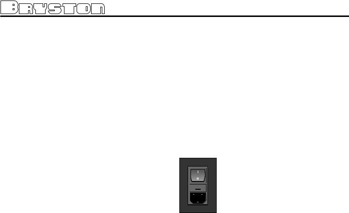
POWER INLET & SWITCH
Located .on .the .right .hand .side .of .the .  rear .panel, .adjacent .to .the .IEC .power . cord .socket .is .a .large .computer-style . switch .that .controls .the .main .electrical .
power .to .the .unit. .This .is .the .ONLY .


 switch .that .actually .completely .turns . off .all .power .to .the .unit. .When .the .SP2 . is .connected .to .an .appropriate .AC .
power .source, .and .the .power .switch .is .switched .to . the .‘I’ .position, .the .unit .automatically .sets .itself . into .a .STANDBY .power .mode, .where-in .only .the . minimum .necessary .circuitry .to .respond .to .the . remote .control’s .power-on .command .or .the . momentary .push-button .power .switch .on .the .front . panel .are .active. .The .RED .standby .LED .on .the . front .panel .illuminates.
. Pressing .the .momentary .POWER .bush-button . switch .on .the .front .panel .or .the .POWER .button .on . the .remote .immediately .takes .the .unit .out .of .its .
STANDBY .mode .into .its .normal .operating .mode. . This .is .indicated .by .the .illumination .of .the .front . panel .LCD .display, .the .illumination .of .the .LED .corresponding .to .the .source .you .last .selected, .and .the . units .LED .operating .mode .indicators.
NOTE:
If your unit’s LCD backlight does not illuminate when the SP2 is plugged into an operating outlet, and switched out of STANDBY mode, please
check to see that the rear panel main power switch {mains switch} is in the ON position.
. If .the .SP2 .is .to .be .unused .for .an .extended . period .of .time .(i.e. .a .vacation) .it .is .strongly .recommended .that .it .be .turned .off .using .the .main .power . switch .on .the .back .panel. .
3

SP2 PREAMP/PROCESSOR
SP2 FRONT PANEL CONTROLS & INDICATORS
|
|
|
|
|
|
|
|
|
|
|
|
|
|
|
|
|
|
|
|
|
|
|
|
|
|
|
|
|
|
|
|
|
|
|
|
|
|
|
|
|
|
|
|
|
|
|
|
|
|
1: |
POWER SWITCH (momentary) |
11: MONO & MONO DOWNMIX MODE Switch & Indicator |
||
2: |
STANDBY & INFRA-RED ACTIVITY INDICATOR |
12: THX Button & Indicator |
||
3: |
INFRA-RED RECIEVER (sensor) |
13: MODE Button & Indicator |
||
4: |
DYNAMIC RANGE CONTROL |
14: BYPASS Button & Indicator |
||
5: |
ALPHA-NUMERIC DISPLAY |
15: ANALOG BALANCE Control |
||
6: |
MENU CONTROL Buttons |
16: MASTER VOLUME Control |
||
7: |
SOURCE SELECT Buttons & Indicators |
See detailed descriptions of these switches, controls and indicators on |
||
8: |
DIGITAL MODE Switch & Indicator |
|||
9: |
SURROUND MODE Switch & Indicator |
pages 3 through 7) |
||
10: |
STEREO & STEREO DOWNMIX MODE Switch & Indicator |
|
|
|
|
|
|
|
|
FRONT PANEL CONTROLS & INDICATORS
1: POWER BUTTON
Pressing .this .push .button .switch .takes .the .unit . in .and .out .of .its .Standby .power .mode. .See .also .
”POWER .INLET .& .SWITCH” .elsewhere .on .this .page.
2: STANDBY & INFRA-RED ACTIVITY INDICATOR
If .this .LED .is .continuously .red, .it .is .an .indication . that .the .SP2 .is .in .Standby .mode. .When .the .SP2 . is .powered .up, .the .LED .is .OFF, .and .flashes .(Red) . when .a .valid .IR .code .is .detected.
3: INFRA-RED SENSOR
Receives .infra-red .remote .control .signals
4: DYNAMIC RANGE CONTROL
This .push .button .switch .permits .the . selection .of .three .dymanic .range .(or . compression) .levels .of .signal .sources . producing .a .Dolby .Digital .or .DTS . encoded .bitstream. .The .Dynamic .
Range .Control .has .no .effect .with .PCM .
 and .Analog .input .signals.
For .the .majority .of .applications .the .MEDIUM .setting .should .be .used. .If .you .wish .to .turn .off .all .of . the .software’s .built-in .dynamic .range .management . functions .(no .compression .and .thus .maximum .
dynamic .range) .the .switch .can .be .set .to .“FULL”.
NOTE: .Caution should be exercised when choosing this option. Many smaller loudspeaker systems cannot handle the extremely wide range signals produced in this mode. Overall system volume should be initially set quite low until you or your dealer are able to determine the maximum safe setting to avoid damage to your loudspeaker systems or power amplifiers.
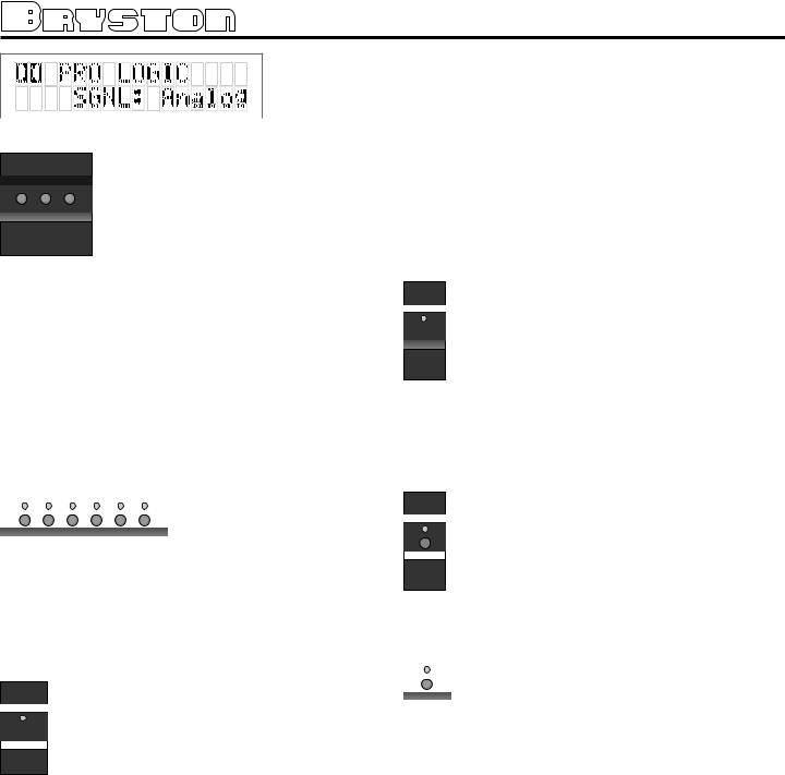
5: ALPHA-NUMERIC DISPLAY
Contains .the .two .line, .black .on .green .16 .character . per .line .alphanumeric .display .which .indicates .the . status .and .functional .mode .of .the .SP2. .This .screen . is .also .used .during .the .menu-setup .function .for . calibration .of .the .SP2 .to .your .system. .If .connected . to .the .Bryston .Video .Switcher, .the .menu-setup .and . status .display .will .also .be .available .on .your .video . monitor .with .On-Screen .Display .(OSD). .
. On .the .first .line, .the .decoding .type .[Dolby . Digital, .DTS, .Pro-Logic, .Music, .etc.] .is .displayed. .
On .the .second .line .the .type .of .signal .being .detected .from .the .currently .selected .input .is .displayed. .A . sample .screen .is .shown .below:
4
6: MENU CONTROL BUTTONS
These .three .buttons .labeled .“”, .“”, . and .“SEL” .(SELECT) .are .used .to .control .the .menu .and .setup .functions .displayed .on .the .LCD. .To .enter .a .menu .

 SEL mode, .you .can .press .any .one .of .these . buttons. .This .will .bring .up .the .main . menu. .Navigating .any .menu .or .sub-
menu .is .done .using .the .two .arrow .(.and .) .buttons. .Once .the .desired .submenu .or .function .is . highlighted, .pressing .“SELECT” .will .make .it .the . current .menu .or .function. .
To. .exit .a .menu, .or .back .up .a .step .use .the .arrow . buttons .to .highlight .the .‘X’ .displayed .in .the .lower . right .hand .corner .of .the .LCD .window .and .press .
“SELECT”, .or .wait .3 .to .4 .seconds .for .the .menu .to . time .out .and .return .to .its .previous .state.
7: SOURCE SELECT BUTTONS & INDICATORS
|
|
Pressing .any .one .of .these . |
|
|
|
|
|
buttons .will .instantly .switch . |
|
|
|
|
|
the .SP2’s .analog .and .digital . |
|
|
inputs .to .read .the .indicated . |
|
|
|
TV/SAT DVD |
CD AUX VCR TAPE |
source. . |
|
|
|
|
|
If .the .SP2 .is .in .its .digital . |
|
|
mode, .as .soon .as .any .input . |
is .selected .and .switched, .the .decoder .will .auto- |
||
matically .try .to .determine .the .new .bitstream’s .type . and .mode. .
8: DIGITAL MODE SELECT BUTTON & INDICATOR
This .button .operates .as .a .three-way .toggle .  function. .The .LED .immediately .above .the .
button .has .two .colors .- .RED .and .GREEN, .
 and .an .OFF .mode .where .it .is .not .illuminat-
 MODE ed. .
When .Digital .Mode .is .selected, .the .decoder . will .automatically .default .to .a .digital .signal .for .the . selected .input .if .one .is .present. .
. If .a .digital .signal .is .present .and .detected, .the . SP2 .will .automatically .determine .the .type .of .bitstream .and .select .the .proper .decoding .mode. .The . indicator .LED .will .turn .green .when .this .happens. .
. If .NO .DIGITAL .SIGNAL .is .detected .the .SP2 .will . default .back .to .the .analog .input .for .the .selected . source. .This .also .automatically .puts .the .SP2 .into . its .Digital .Standby .Mode. .When .this .occurs .the .LED . indicator .will .turn .RED .
. In .this .mode, .the .decoder .will .continually .check . the .selected .source .inputs .for .the .presence .of .a . digital .signal. .If .one .is .detected, .the .SP2 .will .auto- matically .switch .over .to .the .pre-selected .digital .
operation .mode .for .that .source. .
. To .defeat .this .auto-digital .detect .mode .you . must .press .the .button .again. .If .you .do .the .LED .will . go .OFF. .
. When .this .mode .of .operation .is .selected .the . SP2 .will .look .at .ONLY .its .analog .inputs. .If .a .digital . signal .does .appear .the .SP2 .will .NOT .recognize .it . and .will .remain .in .its .analog .only .mode .until .you . press .the .Digital .button .again .to .either .select .the . digital .source .or .place .the .SP2 .into .its .auto .detect . mode .as .explained .above.
9: SURROUND MODE BUTTON & INDICATOR
Pressing .this .button .will .engage .the .SP2’s .

 surround .listening .mode. .When .this .function .
is .operational .the .LED .will .turn .green. .For .
 Dolby .Digital .and .DTS .bitstreams, .the .signal . SURROUND will .be .decoded .and .presented .with .no .addi- tional .post-processing. .For .2-channel .source .
material, .the .SP2 .will .synthesize .surround . information .based .on .the .chosen .Surround .Mode . (see .Appendix A: SP2 Surround Modes .for .more . information).
10: STEREO & STEREO DOWNMIX MODE
If .this .button .is .selected .and .the .supplied . 
 bitstream .is .more .than .2 .channels, .the .
decoder .will .automatically .implement .a .ste-
 reo .downmix. .Otherwise, .analog .or .digital . STEREO two .channel .signals .are .passed .as .conven-
tional .stereo.
11: MONO & MONO DOWNMIX MODE
|
|
If .this .button .is .selected .and .the .supplied . |
|
||
|
|
bitstream .is .more .than .1 .channel, .the .SP2 . |
|
|
|
|
|
software .will .create .a .Mono .mix .of .all .sig- |
|
|
nals. .If .the .centre .channel .is .present, .the . |
|
|
|
MONO |
|
Mono .signal .will .appear .in .the .centre .chan- |
|
|
|
|
|
nel. .If .no .centre .channel .is .present, .the . |
|
||
mono .signal .will .appear .simultaneously .on .the . |
||
Left/Right .speakers. . |
||
NOTE: Downmix [stereo or mono] is a software based automatic mixing function available within the SP2. This process exists because whenever the number of active decoder outputs or loudspeakers selected in setup is less than the number of channels in the Dolby Digital program, some channel combining will be necessary to present the program on the available number of channels/loudspeakers.
As .a .part .of .any .program’s .production, .its .producers .can .set .and .adjust .the .type .and .ratios .allowed . for .downmixing .somewhat .to .ensure .optimum . results .without .compromising .the .full .Multichannel . balance. .This .is .accomplished .by .including .specific . data .within .the .Dolby .Digital .bitstream .which .rep-
5
 Loading...