


9BSST
POWER AMPLIFIER OWNER’S MANUAL
UPDATED 2007-01-08

9BSST FIVE CHANNEL POWER AMPLIFIER
Table of Contents
|
General Introduction |
Page 1 |
|
Instalation and Ventilation |
|
|
Rear Panel Input Settings/Connections |
Page 2 |
|
Setting Input Selector Switch |
|
|
Balance Input Connector Configuration |
|
|
Setting Polarity |
|
|
Setting Input Sensitivity |
|
|
Output Binding Posts and Polarity |
Page 3 |
|
Front Panel Description |
Page 4 |
|
LED Indicators (Power-up Sequence) |
|
|
LED Indicators (Operating Conditions) |
|
|
Power Control Panel |
Page 5 |
|
Master Curcuit -Breaker |
|
|
AC Power Input |
|
|
Local/Auto Switch |
|
|
Local/External Switch |
|
|
Rack Mounting Instructions |
Page 6 |
|
Individual Module Removal |
|
|
Channel Fuse Type/Location |
|
|
5.1 Typical Home Theatre Setup |
Page 7 |
|
Block Diagram of the 9BSST |
Page 8 |
|
Typical Performance Graphs |
Page 9-10 |
|
Bridging Channels |
Page 11 |
|
External Dimensions |
Page 12 |
|
Technical Specifications |
Page 13 |
|
Important Warranty Information |
Back Cover |
|
|
|

9BSST FIVE CHANNEL POWER AMPLIFIER
Introduction
Thank you for choosing the 9BSST Five Channel Power Amplifier.
Bryston welcomes any suggestions you may have, or comments regarding the operation of your amplifier. We consider you, our customer, to be Bryston’s most important resource, and your opinion is very much appreciated.
Description
The 9BSST is a modular design 5 x 120 Watts per channel audio power amplifier. Each channel selects a balanced or single ended input. Each channel selects a gain of 29dB(1v), 23dB(2v) or 17dB(4v). Each channel input may be operated inverted or non-inverted operation (0 or -180 degrees). The power up of the 9BSST may be controlled by a remote control voltage. The 9BSST includes ‘soft start’ power control circuitry to eliminate high inrush currents when A/C power
is applied.
Warranty ( see back page for details )
Shipping Box & Packing Material
Please keep the original shipping box and all packing material. This will ensure the amplifier is protected in future transport. In the unlikely event you have a problem and must return it for service you must use the proper packing material. Ship the amplifier only in the original packing material, as the unit is not insurable by carriers otherwise.
Installation ( see rack mounting section if applicable )
Ventilation. The most important installation consideration is ventilation. The 9BSST is a convection-cooled amplifier. Unrestricted air-flow across its heat sinks is a must. For this reason do not install anything directly above it. Allow 3.5” (2u) to 5” (3u) inches of space above and to the sides of this amplifier. Do not install directly above other heat generating equipment. Should your installation conditions be constricted, then additional forced air-cooling may be necessary. Bryston can provide an optional fan package if required. Any 9BSST channels thermally shutting down during operation indicates insufficient cooling, and a remedy must be found for cooling the amplifier. Provide a minimum 6” space to the rear of the 9BSST for ventilation and dressing cables to and from the amplifier.
Never operate the 9BSST in a vertical position.
Wiring the 9BSST ( also see rear panel description )
Speaker wires should be as short as practical. Use quality wire, and if runs are more than 3 meters use at least 12 gauge wire. The speaker binding posts will accept wire up to 3 gauge in size. Bryston can custom build cables for your application.
A/C power
Before plugging in the power cord be sure your 9BSST is specified for the correct A/C voltage for your locality. The voltage is listed to the right of the power input connector. The circuit feeding the 9BSST should be sufficient so as not to cause the circuit breaker to trip. Note: the 9BSST when operated with all channels at maximum power into 4 ohm loads, can consume all the available power in a normal household circuit, therefore a dedicated electrical circuit may be necessary with this situation. Never lift the safety ground to the amplifier or remove the ground pin from the plug.
Power line conditioners will not improve the 9BSST performance, in fact most of the time they restrict the flow of current in the power line to the amplifier, reducing performance at high output levels.
1

9BSST FIVE CHANNEL POWER AMPLIFIER
Rear Panel Input / Output Connections
1. Input Select Switch.
Each 9BSST channel gives the user the option of switching between either balanced input or single ended input.
2. Balanced Input connector. ( Imp. 20k )
This input connector accepts standard ‘XLR’ or 1/4” TRS . Use quality, 100% shielded cables with gold plated connectors.
‘XLR’ type
‘TRS’ type
‘RCA’ type
3. Single Ended Input. ( Un-balanced input ) ( Imp. 50k )
This input connector accepts standard ‘RCA’ or ‘Phono’ connectors.
Use quality, 100% shielded cables with gold plated connectors.
Balanced input Vs Single ended input:
The balanced input requires a balanced pre-amp source. Balanced systems provide noise protection from external electrical interference, so cable length can be very long (50m or longer ).
The single ended or unbalanced input is provided for pre-amps without balanced output. Single-ended cables should be kept to 20’ (7m) or less. In general never use longer cables than necessary, never coil excess cable length, and run signal wires away from AC power or speaker cables.
4. Polarity Switch ( 0 or -180 degrees)
Each 9BSST channel gives the user the option of inverting the polarity of the input signal -180 degrees. Polarity inversion is application specific. The normal operating position is 0 degrees.
5. Input Sensitivity (Gain) Switch.
The optimum gain setting will depend upon the source pre-amp operating level, and or personal preference.
The 1v setting is used when the source is single-ended, or from a transformer coupled balanced source. This is the home theatre setting for single ended or un-balanced operation.
The 1v setting provides the most amplifier gain - 29 dB. (1v in = 100w @ 8 ohms.) (noise -110 dB) A signal level of 1.1v at the input is required to deliver 120W into 8 ohms (rated output).
The 2v setting is used when the sources output is actively Balanced.
This is the home theatre setting for balanced operation Or use this setting with any systems where the volume control rotation is limited to the bottom half of the control or less.
The 2v setting provides an amplifier gain - 23 dB. ( 2v in = 100w @ 8 ohms.) ( noise -112 dB ) A signal level of 2.2v at the input is required to deliver 120W into 8 ohms (rated output).
The 4v setting is used when the source pre-amp has a high output level, or in ultra sensitive systems where the volume control rotation range is still limited when using the 2v setting.
Some pre-amps may be unable to deliver enough level to use this setting.
The 4v setting provides an amplifier gain - 17 dB. ( 4v in = 100w @ 8 ohms.) ( noise -115 dB ) A signal level of 4.4v at the input is required to deliver 120W into 8 ohms (rated output).
The noise is referenced in dB below rated output of 120 watts. Different input configurations result in slightly different noise readings. The above noise ratings represent minimum readings, actual readings may be better.
2
9BSST FIVE CHANNEL POWER AMPLIFIER
6. Output binding posts
The RED binding post is connected to the amplifier output. Connect to this post the (+) terminal on the loudspeaker. The BLACK binding post is connected to signal ground. Connect to this post the (-) terminal on the loudspeaker.
When the polarity switch is set for 0 degrees (normal operation ) the output at the RED binding post is in phase with the input signal.
When the polarity switch is set for 180 degrees (inverted operation) the the output at the RED binding post is 180 degrees out of phase with the input signal.
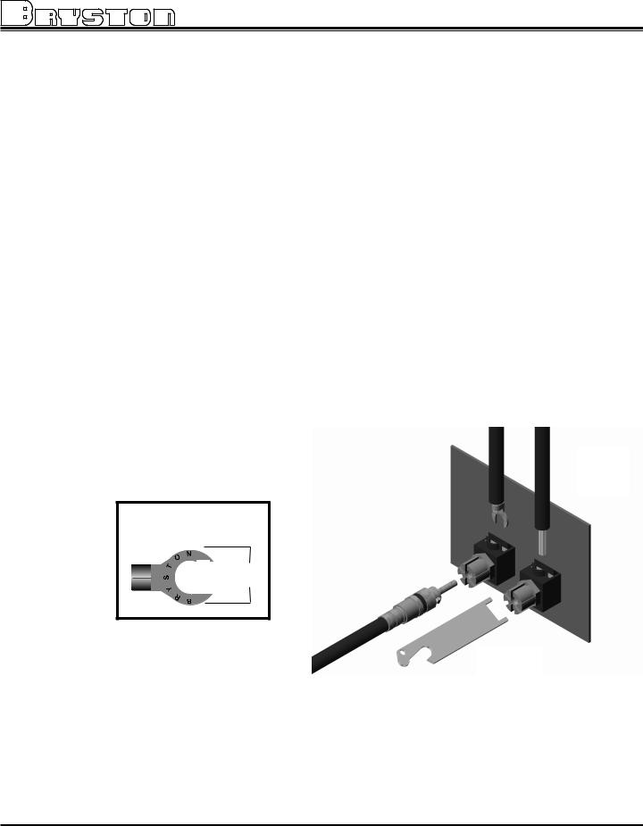
The Output binding posts provide three different interconnect options. Combinations may be used when bi-wiring. See figure 2 below. Cables should be kept as short as practical and should never be terminated with connectors that may become confused for AC power connectors. Cables should be dressed away from input and power cables.
1. Banana plugs offer a quick disconnect option. Before inserting a banana plug into the binding post be sure to tighten the post nut to avoid rattling and to provide full insertion of the banana plug. Gold plated locking banana plugs are available from Bryston.
2. Spade lugs provide high contact area and secure fastening. Lugs should be gold plated. See diagram for details. Post diameter is 5/16’ ( 8mm ),lug width 5/8” (16 mm). Gold plated spade lugs are available from Bryston.
3. Stripped bare wire up to 3 gauge can be inserted through the hole in the binding post and held in place by tightening the post knob. Additional tightening pressure can be achieved using the wrench provided in the slots of the knob. Do not over tighten or the binding post may become damaged. Note that copper wire is malleable and may require further tightening after the initial installation.
Spade lug dimensions
5/16” |
”5/8 |
Fig 2
2
3
1
wrench or coin
3
 Loading...