


SP1.7

SP1.7
SERIES
INSTRUCTIONS FOR BRYSTON
SP1.7 PRECISION
PREAMPLIFIER/PROCESSOR

IMPORTANT SAFETY INSTRUCTIONS
The lightning flash with arrowhead symbol within an equilateral triangle, is intended to alert the user to the presence of un-insulated
“dangerous voltage “ within the product’s enclosure that may be of sufficient magnitude to constitute a risk of electric shock to
persons.
The exclamation point within an equilateral triangle is intended to alert the user to the presence of important operating and maintenance
(servicing) instructions in the literature accompanying the product.
1. Read these instructions.
2. Keep these instructions.
3. Heed all warnings.
4. Follow all instructions.
5. Do not use this apparatus near water.
6. Clean only with dry cloth.
7. Do not block any ventilation openings. Install in accordance with the manufacturer’s instructions.
8. Do not install near any heat sources such as radiators, heat registers, stoves, or other apparatus (including amplifiers) that produce heat.
9. Do not defeat the safety purpose of the polarized or grounding-type plug. A polarized plug has two blades with one wider than the other. A
grounding type plug has two blades and a third grounding prong. The wide blade or the third prong are provided for your safety. If the pro-
vided plug does not fit into your outlet, consult an electrician for replacement of the obsolete outlet.
10. Protect the power cord from being walked on or pinched particularly at plugs, convenience receptacles, and the point where they exit from the
apparatus.
11. Only use attachments/accessories specified by the manufacturer.
12. Use only with the cart, stand, tripod, bracket, or table specified by the manufacturer, or sold with the apparatus. When a cart is
used use caution when moving the cart/apparatus combination to avoid injury from tip-over.
13. Unplug this apparatus during lightning storms or when unused for long periods of time.
14. Refer all servicing to qualified service personnel. Servicing is required when the apparatus has been damaged in any way, such as power-
supply cord or plug is damaged, liquid has been spilled or objects have fallen into the apparatus, the apparatus has been exposed to rain or
moisture, does not operate normally, or has been dropped.
WARNING: TO REDUCE THE RISK OF FIRE OR ELECTRIC SHOCK, DO NOT EXPOSE THIS APPARATUS TO RAIN OR MOISTURE.
DO NOT EXPOSE THIS EQUIPMENT TO DRIPPING OR SPLASHING AND ENSURE THAT NO OBJECTS FILLED WITH LIQUIDS, SUCH AS VASES, ARE
PLACED ON THE EQUIPMENT.
TO COMPLETELY DISCONNECT THIS EQUIPMENT FROM THE AC MAINS, DISCONNECT THE POWER SUPPLY CORD PLUG FROM THE AC
RECEPTACLE.
THE MAINS PLUG OF THE POWER SUPPLY CORD SHALL REMAIN READILY OPERABLE.
BRYSTON LIMITED WARRANTY
Bryston analog audio circuits are warranted to be free from manufacturing defects for twenty (20) years from the original date of manufacture. The
warranty includes par ts and labour.
Bryston Digital circuits and cables are warranted for five years from the original date of manufacture. The warranty includes parts and labour.
Bryston products having motorized moving parts, excluding motorized volume controls, are warranted for three years from the original date of manu-
facture. The warranty includes parts and labour.
Bryston will remedy the problem by repair or replacement, as we deem necessary, to restore the product to full performance. Bryston will pay ship-
ping costs one way (usually the return portion) during the first three years of warranty coverage.
In the event of a defect or malfunction, contact Bryston’s repair centers for return authorization. Products must be returned using original packaging
material only. Packing material may be purchased from Bryston if necessary. This warranty is considered void if the defect, malfunction or failure of the
product or any component part was caused by damage (not resulting from a defect or malfunction) or abuse while in the possession of the customer.
Tampering by persons other than factory authorized service personnel or failure to fully comply with Bryston operating instructions voids the warranty.
This warranty gives you specific legal rights and you may also have other rights which may vary from province to province and country to country.
As of 2006-02-22 Bryston will only warranty Bryston products purchased through authorized Bryston dealers. Bryston products with a date code
of 0608 or higher (date code format is “yyww”, where “yy” is the two least significant digits of the year and “ww” is the week of the year) must be
accompanied by a copy of the bill-of-sale from a Bryston authorized dealer to qualify for warranty service. The warranty is transferable from the original
owner to a subsequent owner as long as a copy of the bill-of-sale from the original authorized Bryston dealer accompanies the re-sale. The copy of the
bill of sale to any subsequent owner need ONLY include the Name of the Bryston Authorized Dealer and the Model and Serial number of the Bryston
product The warranty will only be honored in the country of the original purchase unless otherwise pre-authorized by Bryston.
Postal address: P.O. BOX 2170, Stn. Main
PETERBOROUGH, ONTARIO
CANADA K9J 7Y4
Courier address: 677 NEAL DRIVE
PETERBOROUGH, ONTARIO
CANADA K9J 6X7
PHONE: 705-742-5325
FAX: 705-742-0882
E-mail: cdnser@bryston.ca
79 COVENTRY ST., Suite 5
NEWPORT, VERMONT
U.S.A. 05855-2100
PHONE: 802-334-1201
FAX: 802-334-6658
E-mail: usaser@bryston.ca
BRYSTON SERVICE in CANADA: BRYSTON SERVICE in the USA:
contact your local distributor or
CHECK OUR WEB SITE: www.bryston.ca
E-MAIL BRYSTON DIRECTLY: cdnser@bryston.ca
FAX BRYSTON DIRECTLY: 01-705-742-0882
PHONE BRYSTON DIRECTLY: 01-705-742-5325
BRYSTON SERVICE outside Canada and the USA:

1. Introduction . . . . . . . . . . . . . . . . . . . . . . . . . . . . . . . 1
2. Front Panel Controls and Indicators . . . . . . . . . . . . . . 4
a. Using the Dynamic Range Control . . . . . . . . . . . . . . . . . 5
3. Rear Panel Input and Output Connections . . . . . . . . . . . 12
a. Setting the Optical Input Assign . . . . . . . . . . . . . . . . . . . 13
b. Programming the AUX Trigger Output . . . . . . . . . . . . . . 14
4. SP1.7 Remote Control . . . . . . . . . . . . . . . . . . . . . . . . 15
Table of 5. Setup and Calibration of the SP1.7 . . . . . . . . . . . . . . . 18
a. Explanation of ‘Saved Settings per Source’ . . . . . . . . . . 19
Contents b. Setting the Speaker Configuration . . . . . . . . . . . . . . . . . 19
c. Explanation of ‘Xtra Bass’ Mode . . . . . . . . . . . . . . . . . . 20
d. Enabling the Subwoofer output in the Bypass mode . . . . 21
e. Setting the Speaker Crossover Frequency . . . . . . . . . . . . 21
SP1.7 f. Setting the Channel Delays . . . . . . . . . . . . . . . . . . . . . . . 22
SERIES g. Calibrating and Setting Levels/Channel to . . . . . . . . . . . 23
Channel Balance
h. Setting the THX Subwoofer Limiter or Bass Peak . . . . . 24
Level Manager
i. Enabling DTS-ES 6.1 Decoding . . . . . . . . . . . . . . . . . . . 25
j. Enabling THX Surround EX™ Decoding . . . . . . . . . . . . 26
k. Changing Dolby PLII Music Settings . . . . . . . . . . . . . . . 27
l. Changing DTS NEO:6 Settings . . . . . . . . . . . . . . . . . . . 29
6. Appendix A – SP1.7 Surround Modes . . . . . . . . . . . . . 31
7. Appedix B – THX information . . . . . . . . . . . . . . . . . . . 34
8. Example Hook-up Diagram . . . . . . . . . . . . . . . . . . . . 35
9. SP1.7 Specifications . . . . . . . . . . . . . . . . . . . . . . . . . 36
10. Suggested Surround Sound Placement . . . . . . . . . . . . . 37
INTRODUCTION
Congratulations on your purchase of the Bryston SP1.7 pre-amplifier/processor. This product will provide you
with the finest available signal control and DSP audio processing available. Like all Bryston products the SP1.7
has been carefully designed and engineered to deliver a lifetime of enjoyment.
The SP1.7 offers both pre-amplifier and digital decoding functions, and it is very important that you thoroughly
read this manual BEFORE you install and use the SP1.7.
UNPACKING
Your SP1.7 was carefully packed at the factory to protect against any damage in shipping and handling.
Carefully examine the packing and the unit for any signs of external damage or impact and report those to your
dealer or Bryston prior to using the unit.
1
ACCESSORIES
In the carton you should have found the following accessories in addition to the SP1.7:
1 Bryston SP1.7 Instruction Manual
1 Bryston Safety Manual
1 IEC standard power cord
1 SP1.7 Infrared Remote Control unit with backlight and battery installed
It is VERY IMPORTANT that you read and completely understand the Bryston Safety Manual before installing
or connecting the SP1.7 to any electrical power source.
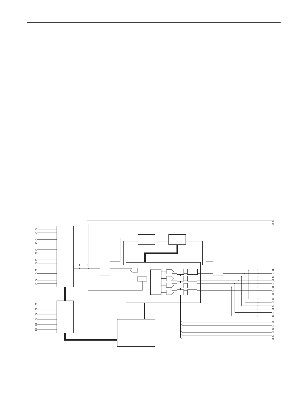
SP1.7 FUNCTIONAL LAYOUT
Below is a block diagram of the Bryston SP1.7. It shows the signal flow
and basic operational structure of the Surround Processor and Preamplifier.
2
BYPASS
SWITCH
DIGITAL
DIGITAL
INPUTS
SELECTOR
SOURCE
SYSTEM
CONTROLLER
INPUTS
STEREO
SELECTOR
SOURCE
ANALOG
S/PDIF
ADC
DAC
DAC
DAC
SWITCH
SELECT
DSP5636x
BYPASS
INPUT
DSP CORE
CONTROL
BALANCE
MOTORIZED
VOLUME POT
BALANCED
OUTPUTS
UNBALANCED
OUTPUTS
RECORD
OUTPUTS
CONTROL
CONTROL
CONTROL
LEVEL
LEVEL
LEVEL
DAC
CONTROL
LEVEL
RELAY
RELAY
RELAY
RELAY
5.1 CHANNEL
ANALOG INPUT
Figure 1: Block Diagram

3
POWER
The SP1.7 uses a dual mode electrical power system. In the
electrical power input module located on the right hand side of
the rear panel, adjacent to the IEC power cord socket is a large
computer-style switch that controls the main electrical power to
the unit. This is the ONLY switch that actually completely turns
off all power to the unit. Please see the illustration adjacent.
When the SP1.7 is connected to an appropriate AC power
source, and the power switch is switched to the ‘I’ position,
the unit automatically sets itself into a STANDBY power mode,
where-in only the minimum necessary circuitry to respond to
the remote control’s power-on command or the momentary
power toggle switch on the front panel are active. The RED
standby LED on the front panel illuminates.
Activating the momentary POWER toggle switch (either up or
down) on the front panel or the POWER button on the remote
immediately takes the unit out of its STANDBY mode into its
normal operating mode.
The presence of AC power to the SP1.7 is indicated by the
illumination of the front panel LCD display, the illumination
of the LED corresponding to the source you last selected, and
the units LED operating mode indicators.
NOTE: If your unit’s LCD backlight does not illuminate
when the SP1.7 is plugged into an operating outlet, and
switched out of STANDBY mode, please check to see that
the rear panel main power switch {mains switch} is in the
ON position.
If the SP1.7 is to be unused for an extended period of time (i.e.
a vacation) it is strongly recommended that it be turned off
using the main power switch on the back panel.
250VA
60Hz
120V
Figure 2: Power Input Mode
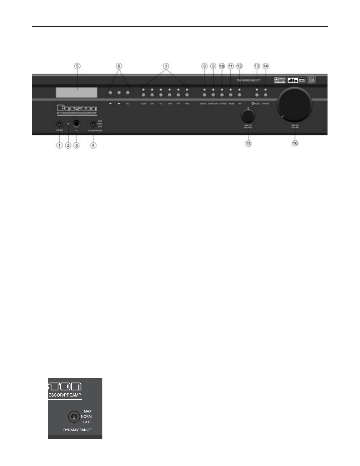
FRONT PANEL CONTROLS AND INDICATORS
When looking at the front panel of the SP1.7 you will see the following
controls and displays from left to right:
1. Power [Momentary Switch]
Toggling this switch up or down takes the unit in and out of its’
Standby power mode.
2. Standby and (IR) Infrared Activity Indicator
If this LED is continuously red, it is an indication that the SP1 is
in Standby mode. When the SP1.7 is powered up, the LED is
OFF, and flashes (Red) when a valid IR code is detected.
3. (IR) Infrared Receiver/Sensor for remote control
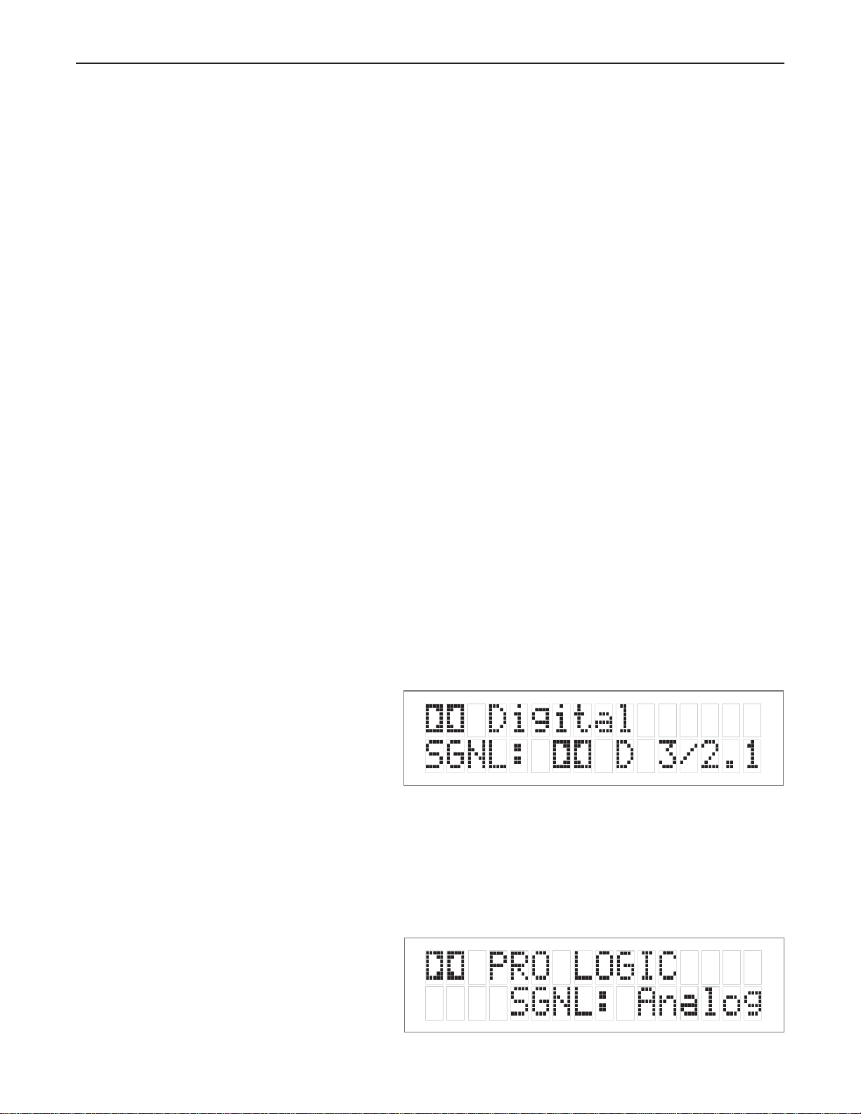
4. Dynamic Range Control
This three position switch permits the adjustment of the dynamic
range (softest sound to loudest sound) of signal sources producing
a Dolby Digital or DTS encoded bitstream. The Dynamic Range
Control has no effect with PCM and Analog input signals.
4
Figure 3: Front Panel
5
USING THE DYNAMIC RANGE CONTROL
For the majority of applications this switch should be placed and remain in the middle or NORM position.
For late night viewing or at any time you wish to reduce the overall dynamic range of a program the switch
may be set to the “LATE” (down) position.
If you wish to turn off all of the software’s built-in dynamic range management functions the switch can be set
to the “MAX” (up) position.
NOTE: Caution should be exercised when choosing this option. Many smaller loudspeaker systems can-
not handle the extremely wide range signals produced in this mode. Overall system volume should be ini-
tially set quite low until you or your dealer are able to determine the maximum safe setting to avoid
damage to your loudspeaker systems or power amplifiers.
5. LCD Display window
Contains the two line, black on green 16 character per line alphanumeric display which indicates the status and
functional mode of the SP1.7. This screen is also used during the menu-setup function for calibration of the SP1
to your system. If connected to the Bryston SPV-1 Video Switcher, the menu-setup and status display will also
be available on your video monitor with On-Screen Display (OSD).
On the first line, the decoding type [Dolby Digital,
DTS, Pro-Logic, Music, etc.] is displayed. A sample
screen is shown below:
On the second line, the type of signal being detected
from the currently selected input is displayed. A sample
screen is shown below:
Figure 4: Status display showing
Dolby Digital 5.1 channel signal at input
Figure 5: Status display showing analog
input signal and Pro Logic decoding
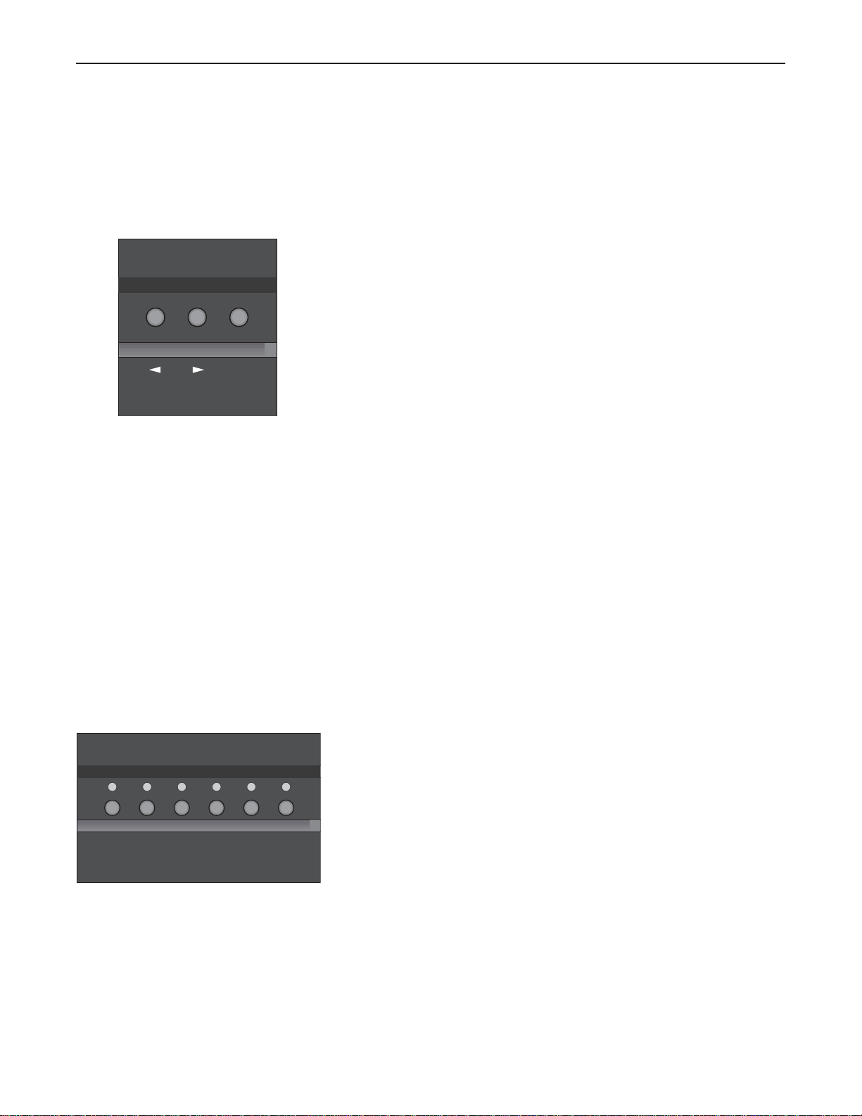
6. Menu Control Buttons
These three buttons labeled “<”, “>”, and “SEL” (SELECT) are
used to control the menu/setup functions displayed on the LCD.
To enter a menu mode, you can press any one of these buttons.
This will bring up the main menu.
Navigating any menu or sub-menu is done using the two arrow
(< >) buttons. Once the desired submenu or function is high-
lighted, pressing “SELECT” will make it the current menu or
function.
To exit a menu, or back up a step use the arrow buttons (< >)
to highlight the ‘X’ displayed in the lower right hand corner of
the LCD window and press “SELECT”.
7.Source Selection Buttons and Indicators
Pressing any one of these buttons will instantly switch the
SP1.7’s analog and digital inputs to read the indicated source.
If the SP1.7 is in its digital mode, as soon as any input is
selected and switched, the decoder will automatically try to
determine the new bitstream’s type and mode.
6
SEL
TV/SAT
TAPEDVD
CD AUX
VCR

7
MODE SELECTION BUTTONS:
8. Digital Mode and Indicator
This button operates as a three-way toggle function. The LED immediately
above the button has two colors - RED and GREEN, and an OFF mode
where it is not illuminated.
When Digital Mode is selected, the decoder will automatically default to a
digital signal for the selected input if one is present.
If a digital signal is present and detected, the SP1.7 will automatically determine
the type of bitstream and select the proper decoding mode. The indicator
LED will turn green when this happens.
If NO DIGITAL SIGNAL is detected the SP1.7 will default back to the analog
input for the selected source. This also automatically puts the SP1.7 into its
Digital Standby Mode. When this occurs the LED indicator will turn RED
In this mode, the decoder will continually check the selected source inputs
for the presence of a digital signal. If one is detected, the SP1.7 will auto-
matically switch over to the pre-selected digital operation mode for that source.
To defeat this auto-digital detect mode you must press the button again. If
you do the LED will go OFF.
When this mode of operation is selected the SP1.7 will look at ONLY its
analog inputs. If a digital signal does appear the SP1.7 will NOT recognize
it and will remain in its analog only mode until you press the Digital button
again to either select the digital source or place the SP1.7 into its auto detect
mode as explained above.
9. Surround Button
Pressing this button will engage the SP1.7’s surround listening mode. When
this function is operational the LED will turn green. For Dolby Digital 5.1,
DTS 5.1, and DTS-ES 6.1 bitstreams, the signal will be decoded and pre-
sented with no additional post-processing. For 2-channel source material,
the SP1 will synthesize surround information based on the chosen Surround
Mode (see 31. for Surround Mode information).
DIGITAL
SURROUND

10. Stereo and Stereo Downmix Mode
If this button is selected and the supplied bitstream is more than 2 channels, the
decoder will automatically implement a stereo downmix. Otherwise,
analog or digital two channel signals are passed as conventional stereo.
11. Mono and Mono Downmix Modes
If this button is selected and the supplied bitstream is more than 1 channel, the
SP1.7 software will create a Mono mix of all signals. If the centre channel is
present, the Mono signal will appear in the centre channel. If no centre channel
is present, the mono signal will appear simultaneously on the Left/Right speakers.
NOTE: Downmix [stereo or mono] is a software based automatic mixing
function a vailable within the SP1.7.This process exists because whenever the
number of active decoder outputs or loudspeakers selected in setup is less than
the number of channels in the Dolb y Digital program,some channel combining will
be necessary to present the program on the available number of
channels/loudspeakers.
As a part of any program’s production, its producers can set and adjust the type
and ratios allowed for downmixing somewhat to ensure optimum results without
compromising the full Multichannel balance. This is accomplished by including
specific data within the Dolby Digital bitstream which represents different mix-
ing coefficients for the centre and surround channel signals.
These will be detected by the SP1.7 and used to produce the downmix if this
mode is selected.
8
STEREO
MONO

9
12. THX Button
Pressing this button will engage the SP1.7’s default THX listening mode. The default mode is selected using the
“EX Control” menu (see page 26).
NOTE:THX Surround EX™ decoding is only available in the THX listening mode.
If the “EX Control” Option is set to OFF, selecting this function (LED green) will automatically incorporate the
THX post processing option for all surround modes. Dolby Digital 5.1, DTS 5.1 and DTS-ES 6.1 bitstreams will
be decoded and presented with THX post-processing.
If the “EX Control” Option is set to ON, selecting this function (LED green) will engage THX Surround EX™
decoding for back channel speaker(s), and incorporate THX post processing, for Dolby Digital 5.1 bitstreams
only. For DTS bitstreams, the signal will be decoded and presented with THX post-processing. THX Surround
EX™ is only available if the back speakers are engaged. If THX Surround EX™ is unavailable, an error message
will appear on the LCD.
If the “EX Control” Option is set to AUTO, selecting this function (LED illuminated) will engage THX
Surround EX™ decoding only for bitstreams that are flagged as having EX encoded content.
NOTE: not all DVDs that are recorded with THX Surround EX contain this flag.
Pressing the THX button repeatedly will toggle between the ON and
DISABLE settings for THX Surround EX™. The default THX
mode will only be engaged when entering the THX mode from
another listening mode (such as Surround or Stereo)
For 2-channel source material, the SP1.7 will synthesize surround
information based on the chosen Surround Mode (see 31. for
Surround Mode information), and add THX post-processing.
NOTE: If the THX listening mode is engaged, PLII Music and
NEO:6 Music are not available, due to THX requirements.
(please SEE Appendix B FOR MORE Information about THX post processing)
THX

13. Mode Button
This button is used to select one of 13 effects for synthesizing surround sound with 2-channel source material.
Pressing the button repeatedly will scroll through the modes:
Available with THX Listening Mode…
■ PLII Film
■ Pro Logic
■ NEO:6 Cinema
Available with Surround Listening Mode…
■ PLII Film
■ PLII Music
■ Pro Logic
■ NEO:6 Cinema
■ NEO:6 Music
■ Stereo5
■ Party
■ Hall
■ Stadium
■ Club
■ Theatre
■ Church
■ Natural
You can select a Surround Mode for the Surround or THX listening
modes at any time, even if the effect is not immediately active (such
as the case when a 5.1 channel bitstream is present). Two Surround
Mode settings are memorized for each input – one associated with
the Surround listening mode, and one associated with the THX
listening mode.
10
MODE
 Loading...