


4B SST

3BSST
4BSST
POWER AMPLIFIER
OWNER’S MANUAL
UPDATED 2007-01-29
3Bsst & 4Bsst POWER AMPLIFIERS
GENERAL INFORMATION
Introduction
Thank you for choosing an SST SERIES Stereo Power Amplifier.
Bryston welcomes any suggestions you may have, or comments regarding the operation of your amplifier. We consider
you, our customer, to be Bryston’s most important resource, and your opinion is very much appreciated.
Description 3B SST
The 3B SST is a dual mono design 2 x 150W per channel audio power amplifier. Each channel selects a balanced or single
ended input. Each channel selects a gain of 29dB(1v) or 23dB(2v). The 3B SST includes ‘soft start’ power control circuitry
to eliminate high inrush currents when A/C power is applied. The power up or turn-on of the 3B SST may be activated by
remote control voltage.
Description 4B SST
The 4B SST is a dual mono design 2 x 300W per channel audio power amplifier. Each channel selects a balanced or single
ended input. Each channel selects a gain of 29dB(1v) or 23dB(2v). The 4B SST includes ‘soft start’ power control circuitry
to eliminate high inrush currents when A/C power is applied. The power up or turn-on of the 4B SST may be activated by
remote control voltage.
Warranty ( see back page for details )
Shipping Box & Packing Material
Please keep the original shipping box and all packing material. This will ensure the amplifier is protected in future transport.
In the unlikely event you have a problem and must return it for service you must use the proper packing material. Ship the
amplifier only in the original packing material, as the unit is not insurable by carriers otherwise.
Installation ( see rack mounting section if applicable )
Ventilation. The most important installation consideration is ventilation. All SST amplifiers are convection cooled.
Unrestricted air-flow across its heat sinks is a must. For this reason do not install anything directly above it. Allow 3.5’
(2u) to 5” (3u) inches of space above and to the sides of this amplifier. Do not install directly above other heat generating
equipment. Should your instillation conditions be constricted, then additional forced air-cooling may be necessary. Bryston
can provide an optional fan package if required. Any SST channels thermally shutting down during operation indicates
insufficient air flow, and a remedy must be found for cooling the amplifier. Provide a minimum 6” space to the rear of the
amplifier for ventilation and dressing cables to and from the amplifier.
Never operate the amplifier in a vertical position.
Wiring the SST amplifier ( also see rear panel description )
Speaker wires should be as short as practical. Use quality wire, and if runs are more than 3 meters use at least 12 gage
wire. The speaker binding posts will accept wire up to 3 gage in size. Bryston will custom build cables for your application.
A/C power
Before plugging in the power cord be sure your SST amplifier is specified for the correct a/c voltage for your locality. The
voltage is listed on the label found at the upper right of the rear panel. The circuit feeding the 4B SST should be sufficient
so as not to cause the circuit breaker to trip (15 amp min). Note: the 4B SST when operated with both channels delivering
maximum power into 4 ohm loads, will consume all the available power in a normal household circuit, therefore a dedicated
electrical circuit may be necessary with this situation. Never lift the safety ground to the amplifier nor remove the ground
pin from the plug.
Power line conditioners will not improve the SST amplifier performance, in fact most of the time they restrict the flow
of current to the amplifier, reducing performance at higher output levels
1
3Bsst & 4Bsst POWER AMPLIFIERS
2
2
1
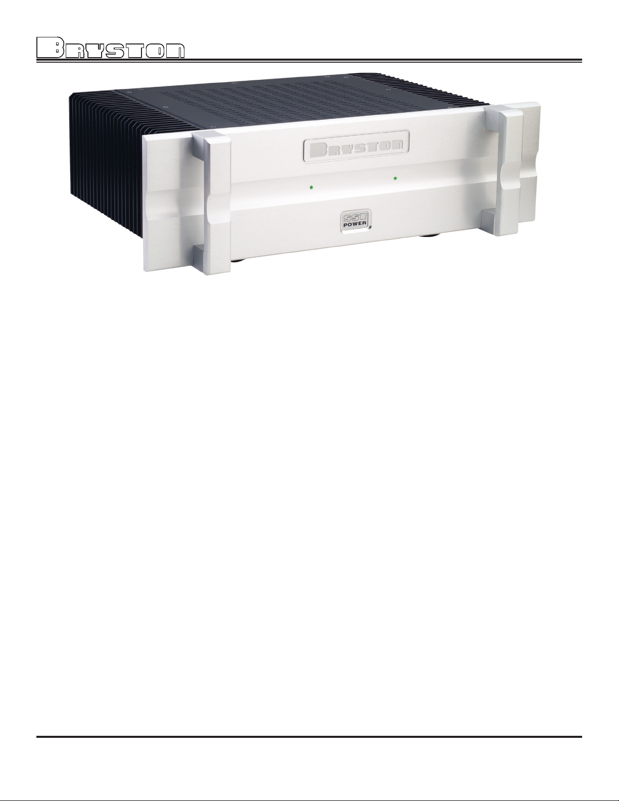
FRONT PANEL
1. 'SST POWER' switch
The front panel label 'SST POWER', is a touch sensitive membrane switch used to apply or remove a/c line power to the
soft start circuitry. Push firmly the center of the switch until the power-up sequence begins. Push again and the amplifier
will power-down. ( Note: the rear circuit breaker must be on for the amplifier to power-up)
2. LED Indicators
Each SST channel has a LED indicator to monitor the following conditions:
Unlit - indicates channel has no power.
Red - indicates channel is muted (power-up)
GReen - indicates channel operation is normal.
FlashinG Red - indicates channel clipping.
ORanGe - indicates channel thermal shutdown.
Power up sequence
After pushing the 'SST POWER' switch, each channel LED will turn from unlit to red (mute). When the power supplies
have stabilized the channel will come out of mute and the LED will change to green (normal operation).
Unlit LED ( No power )
The SST channel LED when unlit indicates no A/C mains power is present at the channel. If both channel LED indica-
tors are unlit the amplifier probably needs only to be powered on.
Clipping ( flashing red )
Clipping occurs when the channel output level no longer can follow the level increase at the input (Overdriven input
condition). When an SST channel is driven into clipping the channel LED will change from green to red then back to
green when the level is reduced ( Flashing Red ). Momentary clipping can be tolerated, however it indicates that maximum un-distorted power has been surpassed and potential speaker damage may result if overload conditions persist.
Any amplifier that is constantly operated into clipping indicates a more powerful amplifier is needed for that application.
Thermal Shutdown ( orange )
Each channel has thermal shutdown circuitry to prevent damage due to overheating.
Should thermal shutdown occur, the channel will mute, and the channel LED will turn orange indicating this condition.
When the channel has cooled to a safe operating condition the channel will return to normal operation. Persistent
Thermal shutdown indicates steps need to be taken to increase airflow across the channel or channels heat sink. (
Also see installation section on ventilation ).
2
 Loading...