

Page 1
Operation
Manual
Upgrade KITI
Page 2

CONTENTS
BEFORE YOU START................................................................................................................. 2
NEW FEATURES ........................................................................................................................ 2
DISPLAYING THE FABRIC WHILE ALIGNING THE EMBROIDERY POSITION.......................... 3
CHANGING THE PATTERN SIZE WHILE MAINTAINING THE DESIRED THREAD DENSITY
(STITCH RECALCULATOR)........................................................................................................ 6
FIND NEW COLOR SCHEMES WITH THE COLOR SHUFFLING FUNCTION........................... 8
The Color Shuffling Function ............................................................................................... 8
Saving and Recalling the Custom Thread Table using USB media ...................................... 10
USING THE CAMERA TO CONNECT PATTERNS ................................................................... 12
Examples of Connected Patterns ........................................................................................ 12
Practice (Connecting Three Patterns) ................................................................................. 13
Changing the Position of a Sticker ..................................................................................... 21
Connecting Rotated Patterns .............................................................................................. 25
Sliding the Position of the Pattern to be Connected ............................................................ 27
Resume Feature ................................................................................................................. 32
NEW PATTERNS...................................................................................................................... 33
Thumbnail List ................................................................................................................... 33
Color Change Table for the Embroidery Patterns ................................................................ 34
1
Page 3

BEFORE YOU START
Note
It is important to perform the upgrade according to the procedure outlined in the Installation Guide. The
machine can then be used as outlined in this upgrade Operation Manual.
• Screen illustrations may vary due to model of machine.
NEW FEATURES
The following features will be activated with the upgrade for Kit I.
• Positioning of the embroidery pattern can be aligned while displaying the fabric being used in the LCD
screen. Embroidery can easily be positioned. (page 3)
• Embroidery patterns can be enlarged or reduced while maintaining their thread density. (page 6)
• Color Shuffling function is added to find new color schemes suggested by your embroidery machine. Select
the desired effect from one of the four available color schemes, then the sample for the selected effect is
displayed. (page 8)
• The custom thread table setting can be saved to USB media as a data file, and then recalled again. (page 10)
• Embroidery patterns can be connected using the built-in camera function, replacing the use of thread marks.
(page 12)
• 10 new embroidery patterns have been added. (page 33)
• 2 new fonts are added to the font selection screen. (page 33)
2
Page 4
DISPLAYING THE FABRIC WHILE ALIGNING THE
Note
Note
EMBROIDERY POSITION
The fabric hooped in the embroidery frame can be
displayed on the LCD so that the embroidery position
can be aligned.
This feature can be used from the pattern editing screen
and embroidering settings screen.
• When installing the following optional frame, the
built-in camera cannot be used to align the
embroidering position:
Cylinder frame, 80 mm (H) × 90 mm (W) (3 inches
(H) × 3-1/2 inches (W))
Wide cap frame, 60 mm (H) × 360 mm (W) (2-3/8
inches (H) × 14 inches (W))
Advanced cap frame 2, 60 mm (H) × 130 mm (W)
(2-3/8 inches (H) × 5-1/8 inches (W))
Advanced cap frame, 50 mm (H) × 130 mm (W) (2
inches (H) × 5-1/8 inches (W)).
• For details on using fabric thicker than 2 mm, refer
to “Positioning the pattern on thick fabric” (page 5).
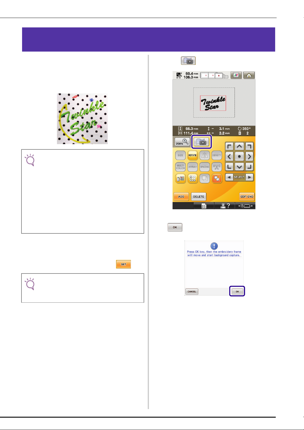
Press .
c
When the following message appears, press
d
.
Hoop the fabric in the embroidery frame, and
a
then attach the frame to the embroidery
machine.
Select the pattern, and then press .
b
• Check page 7/7 of Settings screen to make sure the
“Fabric Thickness Sensor” is set to “OFF” when
using light to medium weight fabrics.
→ The embroidery frame moves so the fabric can be
scanned.
3
Page 5
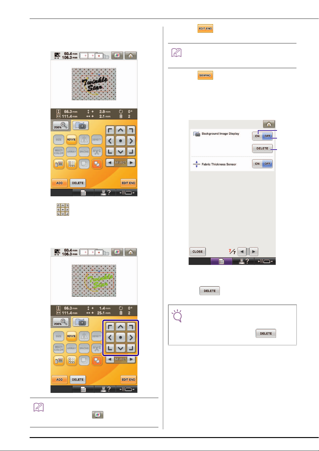
When the fabric appears as a background for
Memo
Memo
Note
b
a
c
e
the pattern, the pattern can be edited if it is
necessary.
Press to display the embroidery
g
settings screen.
• The pattern can also be aligned from the embroidery
settings screen.
Press to start embroidering.
h
→ When embroidery is finished, the fabric displayed in
the background disappears.
Whether the fabric disappears or remains displayed can
be specified from page 7/7 of the settings screen.
Use to align the pattern with the
f
desired embroidery position.
• The pattern can be moved to the desired position by
using your finger or the touch pen to drag the
pattern displayed on the screen.
a Set to “ON” to leave the fabric displayed in the
background.
b When set to “OFF”, the background will disappear.
c Press to remove the background image
completely.
• If the embroidery is not sewn, the fabric background
will remain on the screen.
In the Settings screen 7/7, press to erase
the background image.
4
• If necessary, press to display a preview in
order to check the pattern position.
Page 6
■ Positioning the pattern on thick fabric
Memo
CAUTION
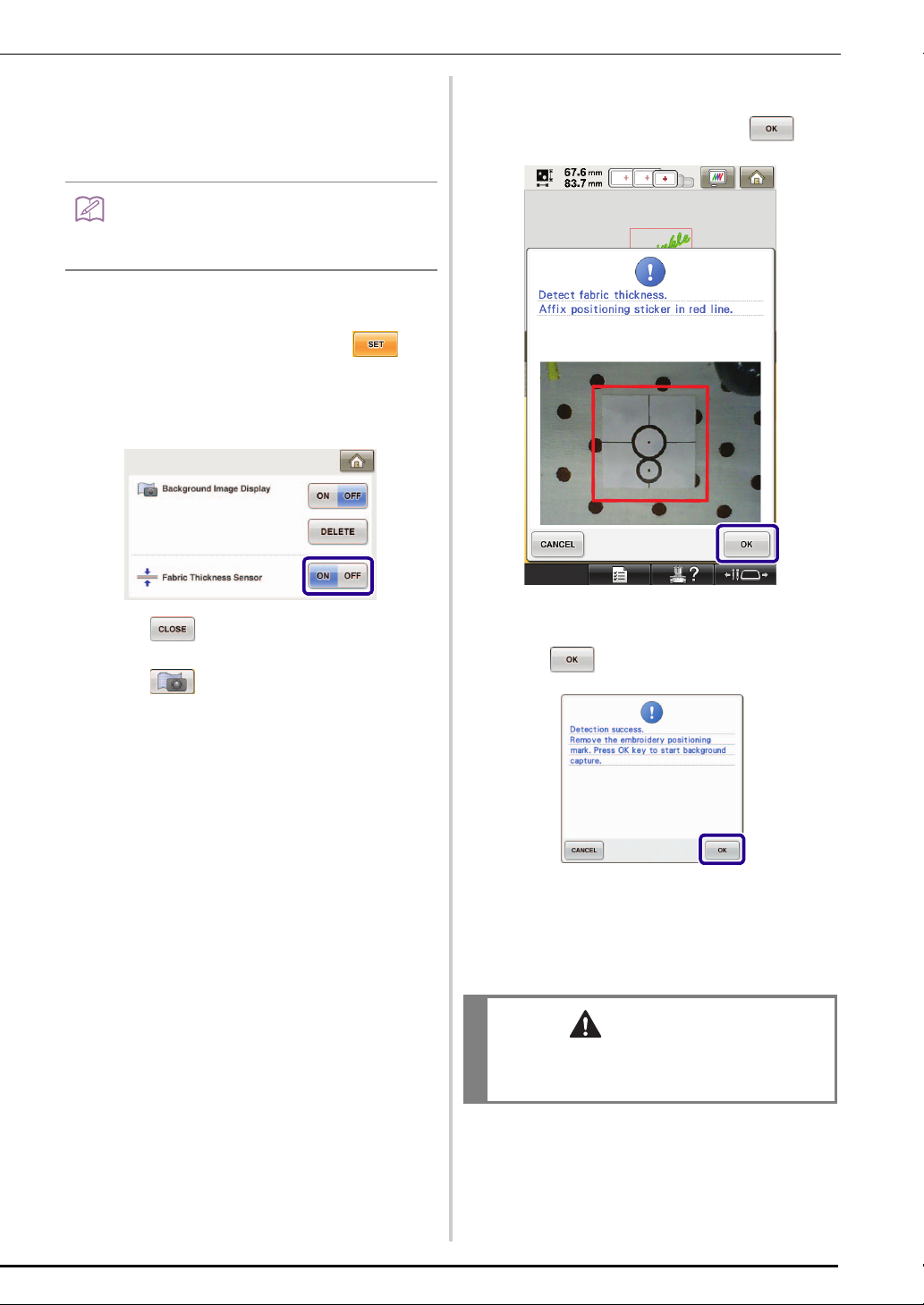
When positioning the pattern on the fabric thicker than
2 mm, the fabric may not be detected correctly. In order
for the fabric to be correctly detected, its thickness must
first be measured.
• This feature is functional only when the fabric is
scanned. It will not affect embroidering if it is turned
on with normal embroidery.
Hoop the fabric in the embroidery frame, and
a
then attach the frame to the machine.
Select the pattern, and then press .
b
Display page 7/7 of the settings screen, and
c
then set “Fabric Thickness Sensor” to “ON”.
Affix the embroidery positioning sticker to the
f
fabric within the area indicated by the red
frame in the LCD, and then press .
d
e
Press .
Press .
When the following message appears, remove
g
the embroidery positioning sticker, and then
press .
→ The embroidery positioning sticker affixed to the
fabric is detected, and then the embroidery frame
will be moved.
Continue with step e on page 4 to align the
h
pattern with the desired embroidery position.
• Use fabrics with a thickness of less than 3 mm
(approx. 1/8 inch). Using fabrics thicker than 3 mm
(approx. 1/8 inch) may cause the needle to break.
5
Page 7
CHANGING THE PATTERN SIZE WHILE MAINTAINING
Note
Note
Memo
THE DESIRED THREAD DENSITY (STITCH RECALCULATOR)
In the embroidery edit screen, the size of the pattern
can be changed while the desired thread density is
maintained.
With this function, the pattern will be enlarged or
reduced at a larger ratio than with normal pattern
resizing.
• Be sure to sew trial embroidery using same fabric
and threads as project in order to check the
embroidering results.
Select the pattern to be resized, and then
a
press .
• This function cannot be used with alphabet
character patterns, frame patterns or border
patterns. However, a border pattern can be edited
after this function has been used.
• Patterns with a large number of stitches (about
100,001 or more) cannot be resized while
maintaining a desired thread density. The maximum
limit for the number of stitches differs depending on
the data size of pattern.
• If this function is used, thread density is maintained
while the pattern is enlarged/reduced. However, the
needle drop point pattern is not entirely maintained.
Use the normal resizing mode depending on
the results of trial embroidering.
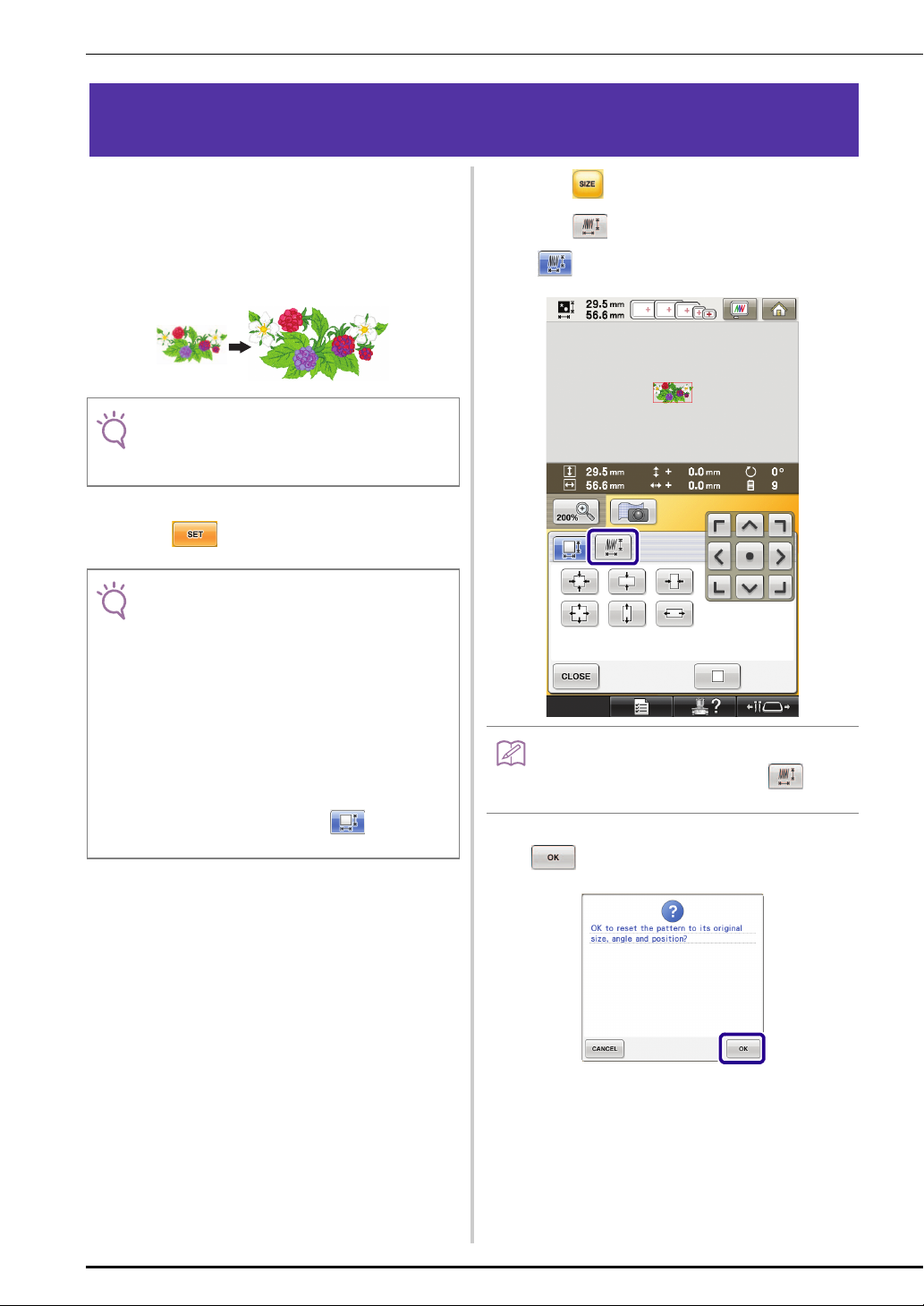
Press .
b
Press to enter Stitch Recalculator mode
c
().
• Stitch Recalculator cannot be used if does
not appear.
When the following message appears, press
d
.
6
→ The pattern will be returned to its original size,
angle, and position as it was before it was edited.
Page 8
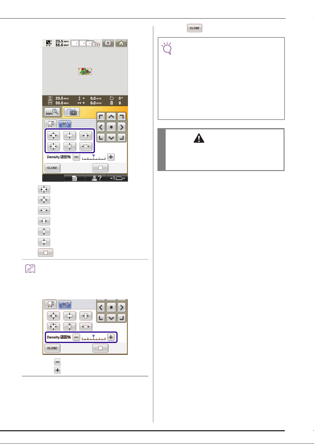
Select how to change the pattern size.
Memo
Note
CAUTION
e
* Press to enlarge the pattern proportionately.
* Press to shrink the pattern proportionately.
Press .
f
• Depending on the pattern, embroidering may not be
possible at the appropriate thread density. Before
sewing on your project, be sure to embroider a trial
sample on a piece of scrap fabric that is the same as
the fabric used in the project, using the same needle
and embroidery thread.
• If the pattern is enlarged and there is space between
stitches, a better effect can be achieved by
increasing the thread density.
• If the pattern is reduced and the stitching is too thick,
a better effect can be achieved by reducing the
thread density.
• Depending on the pattern, the stitching may
become entangled or the needle may break when
the pattern is reduced. If this occurs, slightly
enlarge the pattern.
* Press to stretch the pattern horizontally.
* Press to compact the pattern horizontally.
* Press to stretch the pattern vertically.
* Press to compact the pattern vertically.
* Press to return the pattern to its original appearance.
• With the density scale bar, the thread density can be
changed.
A setting between 80% and 120% in 5% increments
can be specified.
* Press to make the pattern less dense.
* Press to make the pattern more dense.
7
Page 9
FIND NEW COLOR SCHEMES WITH THE COLOR
Note
c
b
a
b
a
SHUFFLING FUNCTION
Select the color group you want to use.
The Color Shuffling Function
With the Color Shuffling function, the machine suggests
new color schemes for the embroidery pattern that you
have selected. After you select the desired effect from
one of the four available color schemes (“RANDOM”,
“VIVID”, “GRADIENT” and “SOFT”) the sample for the
selected effect is displayed.
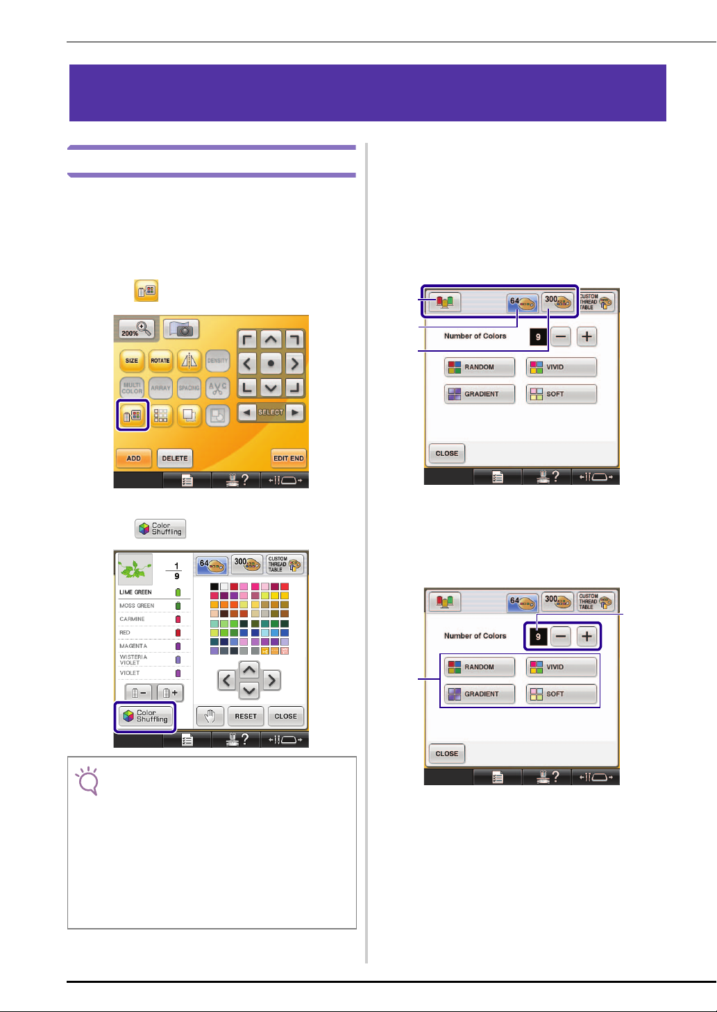
Press .
a
c
→ You can select the color shuffling function from the
following color groups. 1 Thread colors currently
on the spool stand, 2 thread table (64 colors: preset
color table) and 3 custom thread table (300 colors:
color table that you can set as you like).
By setting the embroidery thread colors of the brand
you have on the custom thread table, you can create
your embroidery pattern with your own thread
colors.
Thread colors currently on the spool stand
→ The thread color palette screen appears.
Press .
b
• This function may not be available depending on the
pattern you select (ex. a bordered embroidery
pattern).
If the color shuffling key is grayed out, select
another pattern.
• If you have not created a custom thread table, the
color shuffling key will be grayed out. In that case,
use the thread table (64 colors) instead or create
colors in the custom thread table. Refer to “Creating
a custom thread table” in the Operation Manual of
the machine for the details.
a
b Thread table (64 colors)
c Custom thread table (300 colors)
Select the number of colors you want to use
d
and then select the desired effect.
a Number of colors to be used in the pattern
b Effects for schemes
8
Page 10
Note
• When any of the color scheme selection keys are
Memo
a
Note
a
greyed out, there are not enough colors in the
selected color group.
If you selected the custom thread table, set more
colors in the custom thread table, or select less
colors in the Color Shuffling function. Refer to
“Creating a custom thread table” in the Operation
Manual for the machine, about setting the colors in
the custom thread table.
a Unavailable effects
• Selection for the desired number of colors must stay
within the range for the number of thread changes
for the pattern you selected.
• When using this function the PES data pattern
recalled on the machine, and the “PES Thread
Code” is set to “ON” in the Settings Screen, the
thread colors which are not in the thread table of the
machine will not be used to make the color
schemes.
You can get the color schemes using all the thread
colors in the selected pattern by setting “PES
Thread Code” to “OFF” in the Settings Screen.
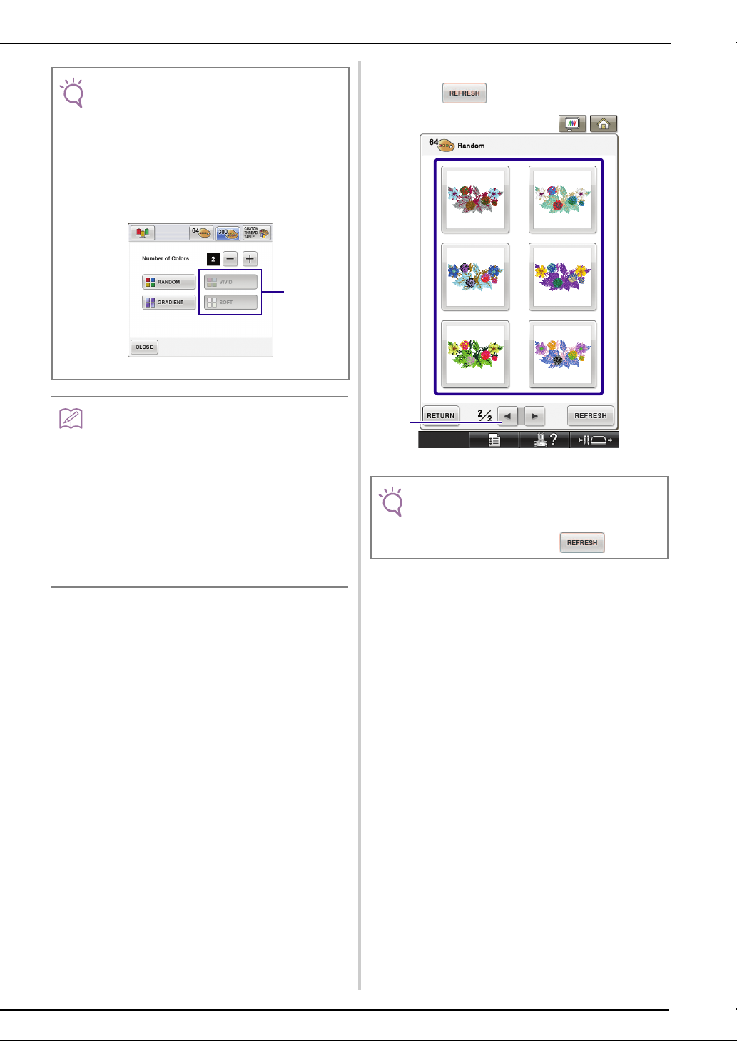
Press the desired color scheme from samples.
e
* Press to display the new schemes.
a Press to review the previous schemes.
• Maximum 10 pages of schemes can be reviewed.
After 10 pages of schemes, the oldest page is
deleted every time you press .
9
Page 11
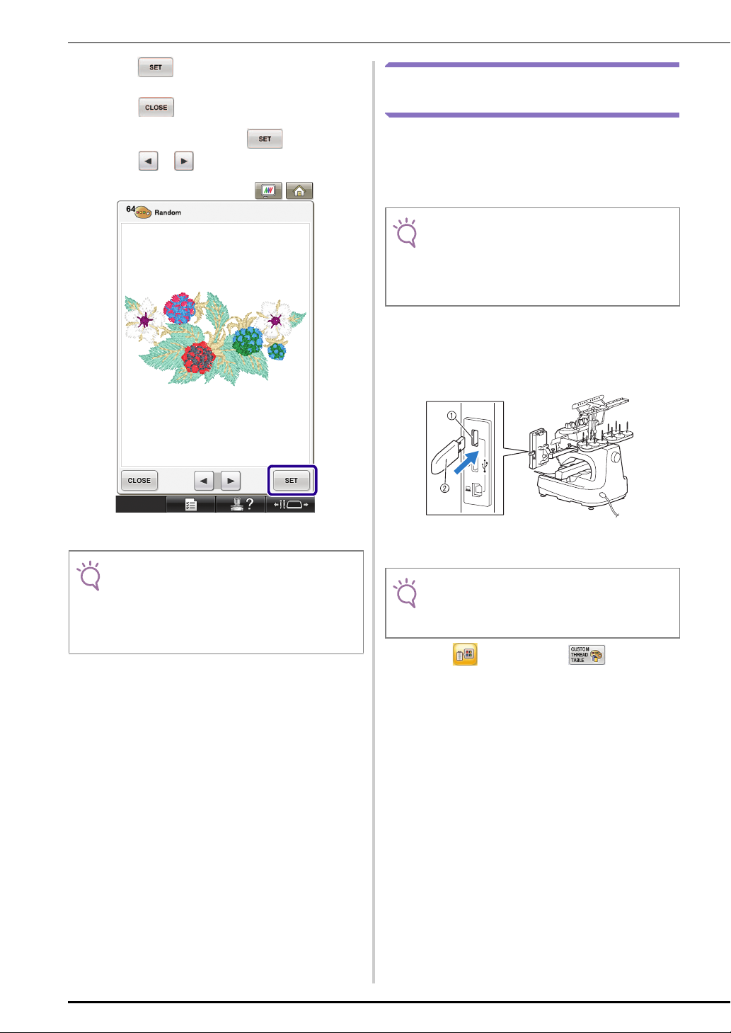
Press to select the displayed color
Note
Note
Note
f
scheme.
* Press to return to the previous screen.
* You can continue selecting color schemes from the
selected page prior to pressing .
* Press or to display the other color schemes.
Saving and Recalling the Custom Thread Table using USB media
You can save a custom thread table data file to USB
media, and then you can recall the saved data from
USB media again. Refer to “Creating a custom thread
table” in the Operation Manual of the machine, for the
detailed instructions about a custom thread table.
• Custom thread table data can only be saved to USB
media. You cannot save the data in the machine’s
memory or in the computer.
• Custom thread table data is saved as “.pcp” data
file.
■ Saving the custom thread table in USB media
Insert the USB media into the primary (top)
a
USB port on the right side of the machine.
→ The embroidery edit screen will appear.
• The following settings in the settings screen cannot
be changed in this function;
- Thread color brand selection
- Reserved needle setting
- PES Thread Code setting
a Primary (top) USB port for media
b USB media
• Two USB media cannot be used with this machine
at the same time. If two USB media are inserted,
only the USB media inserted first is detected.
Press and then press .
b
10
Page 12
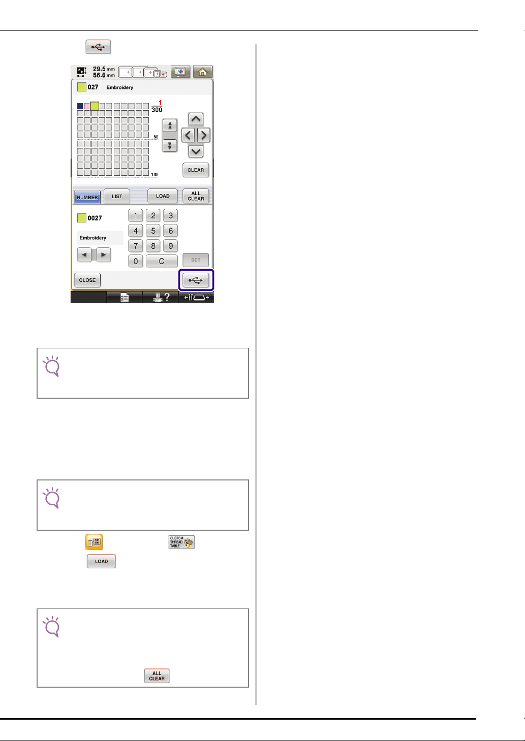
Press .
Note
Note
Note
c
→ The “Saving” screen is displayed. When the data is
saved, the display returns to the original screen
automatically.
• Do not insert or remove USB media while “Saving”
screen is displayed. You will lose some or all of the
data you are saving.
■ Recalling the custom thread table in USB
media
Insert the USB media containing the custom
a
thread table data into the primary (top) USB
port.
• You can only recall one custom thread table data at
a time. Do not store two or more “.pcp” data file in
USB media.
Press and then press .
b
Press .
c
→ The “Saving” screen is displayed. When the data is
loaded to the machine, the display returns to the
original screen automatically.
• Do not insert or remove USB media while “Saving”
screen is displayed. You will lose some or all of the
data you are saving.
• To delete all the specified colors from the custom
thread palette, press .
11
Page 13

USING THE CAMERA TO CONNECT PATTERNS
Note
Instead of using thread marks, the camera can be used to connect patterns.
An area of 17 cm × 33 cm (6-1/2 inches × 13 inches) can be embroidered when the camera is used to connect
patterns. Select the appropriate frame depending on the size of the embroidery. We recommend using the large
embroidery frame (200 mm × 360 mm (7-7/8 inches × 14 inches)) when using the camera to connect patterns.
c
• When installing the embroidery frame (small) (40
mm × 60 mm (1-1/2 inches × 2-3/8 inches), cap
frames, cylinder frame or the round frames, you can
not connect patterns using this function.
• Split (Large-size) embroidery patterns cannot be
used with this function.
• You can not connect patterns using this function
while the machine is set to the Link mode.
Examples of Connected Patterns
Two patterns can be connected by selecting the
reference point and reference edge of each pattern so
that they can be aligned using the camera. When
connecting patterns, the reference edge of each pattern
will be along a single straight line.
d
(Example)
: Reference edge
: Reference point
a
b
e
In order to understand how to connect patterns, first try
following the procedure outlined in “Practice
(Connecting Three Patterns)” on page 13.
12
Page 14

Practice (Connecting Three Patterns)
Note
Memo
In order to practice aligning pattern edges by using the
camera, we will connect three patterns as shown
below. These 3 patterns for practicing are available on
the included CD.
manual sample
Hoop fabric in the large embroidery frame
b
(13 cm × 18 cm (5-1/8 inches × 7-1/8
inches)), and then attach the frame to the
embroidery machine.
Press to display the embroidery
c
settings screen. Press in the embroidery
settings screen.
a Pattern1.pes
b Pattern2.pes
c Pattern3.pes
• Use USB media or a computer to access the pattern
files.
Select the first pattern for practicing [1], and
a
then press .
• needs to be selected in order to continue
connecting patterns.
→ appears at the top left side of the screen,
and then changes to .
• can be pressed while embroidering.
• A pattern cannot be saved in the machine’s memory
while patterns are being connected.
13
Page 15

Press , then press and then
d
press the start/stop button to embroider the
first pattern.
After embroidering of the first pattern is
e
finished, the following message appears. Press
.
When the following message appears, press
f
.
→ Message appears on screen and carriage will move
after pressing .
Select the second pattern [2] for practicing,
g
then press .
14
Page 16

Press , and then select how the pattern
a
h
will be connected.
→ The pattern connection setting screen appears.
When the pattern connection setting screen
i
appears, select the reference edge and
reference point of the first pattern for
connecting the next pattern. Since, in this
example, we will connect the center point of
the right edge for the first pattern with the
center point of the left edge for the next
pattern, select the center point of the right
edge, and then press .
• To cancel the selection, press .
a Reference edge and reference point
15
Page 17

Select the connecting position for the second
Note
c
a
b
Note
j
pattern, and then press . In this
example, select the center point of the left
edge.
Prepare two embroidery positioning stickers.
k
We will follow the on-screen instructions to
affix these two stickers to the fabric so that
the positioning marks can be detected by the
camera.
• Use the positioning stickers included with this
product or purchase replacement stickers (SAEPS2,
EPS2: XF0763-001) from your Brother dealer. If any
other sticker is used, the camera may not recognize
it.
• The 182 mm × 257 mm (7 inches × 10 inches)
embroidery positioning sticker sheet with strong
adhesive is most appropriate for connecting patterns
(SAEPS2, EPS2: XF0763-001). If any other
positioning sticker is used, it may peel off. If the
sticker peels off, the patterns cannot be connected.
Affix the first embroidery positioning sticker
l
onto the fabric within the red lines by using
both hands to press down on each corner of
the sticker. Affix the sticker with the large
circle to the top as shown on machine. Then,
press .
16
a Reference edge and reference point
b Second pattern [2]
c First pattern [1]
→ Message appears on screen and carriage will move
after pressing .
• Using and in this screen, the position of the
second pattern can be changed. For details, refer to
“Sliding the Position of the Pattern to be Connected”
on page 27.
→ The camera detects the first positioning sticker.
Page 18

Note
• Use new positioning stickers. If a sticker is reused, it
may easily peel off. If the sticker peels off during this
procedure, the patterns cannot be connected. Start
the project again with new fabric and stabilizer.
• Using fingers apply pressure to the corners of the
positioning sticker to firmly affix it to the fabric. If the
sticker is not firmly attached, the camera may
incorrectly detect the sticker.
• If any of the following messages appear, reattach
the positioning sticker in the correct position. Make
sure that the sticker is affixed with the large circle at
the top.
Using both hands affix the second embroidery
m
positioning mark within the red lines by
pressing down on each corner of the
positioning mark onto the material and then
touch .
→ The camera detects the second positioning sticker.
17
Page 19

After the two positioning stickers have been
a
Note
n
detected, the following message appears.
a Embroidering area
• If the next pattern and the centers of the large circles
of the two positioning stickers do not fit within the
embroidering area, use a larger embroidery frame. If
a larger embroidery frame cannot be used, continue
o, and then refer to “Changing the Position
to step
of a Sticker” on page 21 to reposition the sticker.
• If the sticker peels off during this procedure, the
patterns cannot be connected. If this occurs, restart
the procedure from the beginning.
Select the area containing one of the two
o
stickers, and then press .
While making sure that the two positioning
stickers do not peel off, remove the
embroidery frame from the machine, and
then rehoop the fabric. Be sure to hoop the
fabric so the next pattern and both the
positioning stickers are within the embroidery
sewing area. Reattach the frame and press
.
→ The camera detects the two positioning stickers.
b Pattern to be embroidered next
c Centers of large circles for stickers
d Embroidery sheet
18
Page 20

Note
• If either of the following messages appear, rehoop
the fabric so that the next pattern and both the
positioning stickers are within the embroidery
sewing area as indicated in the screen.
Press , and then press to detect
the positioning stickers.
After the positioning stickers have been
p
detected, press , and then remove the
stickers.
• Press to remove the positioning stickers
when it’s hard to reach the stickers behind the
needles.
Press , then press and then
q
press the start/stop button to embroider the
second pattern.
→ After embroidering of the second pattern is finished,
the following message appears. Press .
19
Page 21

When the following message appears, press
a
r
.
→ Message appears on screen and carriage will move
after pressing .
Select the third pattern [3] for practicing, and
s
press .
Before embroidering, press to display
t
the pattern connection setting screen. Select
the reference edge and reference point for
connecting the second and third patterns, and
then press . In this example, we will
select the top point of the right edge for the
second pattern.
20
a Reference edge and reference point
Page 22

Select the connecting position for the third
b
a
c
u
pattern and then press . In this
example, we will select the left point of the
top edge for the third pattern.
• Pattern rotates automatically when corner position is
selected.
Press , then press and then
w
press the start/stop button to embroider the
third pattern.
→ After embroidering of the third pattern is finished,
the following message appears. When finished
connecting patterns, press .
→ After embroidering is finished, at the top left
side of the screen disappears.
The three patterns have been connected.
Press to clear the pattern.
Changing the Position of a Sticker
If the selected pattern or positioning stickers for
connecting the next pattern do not easily fit in the
embroidering area, follow the on-screen instructions
that appear after step
the positioning stickers.
For an example, the on-screen instruction appears
when you use the embroidery frame with a size of 10
cm × 10 cm (4 inches × 4 inches) to connect patterns as
shown below.
m on page 17 in order to move
a
Reference edge and reference point
b Third pattern [3]
c Second pattern [2]
Follow the on-screen instruction to perform
v
steps
k to p.
a Pattern1.pes
b Pattern2.pes
21
Page 23

Refer to steps a through m of “Practice
Note
a
a
(Connecting Three Patterns)” using the
embroidery frame with a size of 10 cm x 10
cm (4 inches x 4 inches) to embroider the first
pattern and to connect the second pattern.
Following message appears in step n if the
b
next pattern or affixed positioning stickers are
close to being out of the embroidering area.
Follow the instructions and then press .
• When referring to steps a through m, make sure
you change the reference edge and reference point
to reflect this exercise.
a Embroidering area
a Pattern to be embroidered next
b Embroidery sheet
22
Page 24

Select the area containing one of the two
Note
c
positioning stickers, and then press .
→ The camera detects the two positioning stickers.
After the sticker position is detected, press
d
e
, and then remove the stickers.
Affix the two positioning stickers again
according to the on-screen instructions so
that the next pattern or positioning marks can
fit in the embroidery area.
• If the following message appears, rehoop the fabric
as indicated in the screen, and then press .
→ Press so that the camera detects the first
positioning sticker.
23
Page 25

Affix the second sticker and then press
a
f
.
→ The camera detects the second positioning sticker.
After the two positioning stickers have been
g
detected, the following message appears.
While making sure that the positioning
stickers do not peel off, rehoop the fabric
according to the example displayed on the
on-screen instruction.
a Embroidering area
a Pattern to be embroidered next
b Embroidery sheet
Continue the operation from step o on page
h
18 after pressing .
24
Page 26

Connecting Rotated Patterns
Note
Greater design variations can be created by rotating
patterns. The following procedure describes how to
connect patterns that are rotated.
a Pattern1.pes
b Pattern2.pes
Select the pattern, and then press .
a
Rotate the pattern, and then press .
c
• Be sure to rotate the pattern from the pattern editing
screen. The reference edge and reference point are
specified along the smallest rectangle (not angled)
that contains all patterns selected.
→ The pattern editing screen appears.
Press in the pattern editing screen.
b
Rectangles and angled patterns
a Rectangle
Refer to “Sliding the Position of the Pattern to be
Connected” listed on page 27, to join the first and
the second patterns along an edge.
Rectangles and patterns (not angled)
a Rectangle
• Pressing in the embroidery settings screen
changes the angle at which patterns are connected.
Press to display the embroidery
d
settings screen.
e
Press .
25
Page 27

Refer to steps d through f of “Practice
a
f
(Connecting Three Patterns)” to embroider
the first pattern.
Select the next pattern, and then press .
g
Press in the pattern editing screen.
h
Rotate the pattern to the same angle as the
i
first pattern, and then press .
Select the reference edge and reference point
k
for connecting this pattern to the next one.
Press .
26
j
Press .
a Reference edge and reference point of first pattern
Page 28

Select the reference edge and reference point
a
Note
b
a
l
corresponding to those for the first pattern,
and then press .
Sliding the Position of the Pattern to be Connected
When using the pattern connecting function, patterns
can be connected by sliding them, instead of only
aligning patterns along reference edges and reference
points. This can be done when you want the pattern to
be equally spaced when embroidered. The vertical and
horizontal shifts can be set up to ±99.9 mm.
• The arrangement of patterns displayed in the screen
may differ slightly from the actual embroidery.
Use a ruler to measure the vertical and horizontal
shifts before changing the settings.
m
a Reference edge and reference point
→ Message appears on screen and carriage will move
after pressing .
Continue with step k of “Practice
(Connecting Three Patterns)” to finish
connecting the patterns.
a First pattern
b Second pattern
27
Page 29

■ Connecting Patterns to be Joined Along an
b
a
Note
Edge
Greater design variations can be created by sliding the
patterns being connected.
The following procedure describes how to use this
function to connect patterns so they are joined along an
edge. Before connecting the patterns, the basting
function will be used to measure the distance that the
pattern will be slid.
A: First pattern
B: Second pattern
Measuring the Distance That the Pattern
Will Be Slid
•Steps a through d are for measurement
placement only. Be sure to sew trial embroidery
using same fabric and threads as project in order to
check the embroidering results.
a First pattern
b Second pattern
c Vertical distance : - 15.0 mm
d Horizontal distance : + 40.0 mm
Set “Basting Distance” in the settings screen
a
to “0.0”.
28
Page 30

Select the pattern whose slide distance is to
b
be measured.
Continue to the embroidery settings screen,
c
and then press to select the basting
function.
After the pattern is sewn, remove the fabric
d
from the frame, and then measure the
distance that the pattern is to be slid.
a Vertical: 32.8 mm
b Horizontal: 42.8 mm
Trial Sewing
Sew trial embroidery to check that the pattern will be
slid the correct distance.
Select the pattern, and then continue to the
a
embroidery settings screen.
Press in the embroidery settings screen.
b
Embroider the first pattern.
c
Refer to steps e through h of “Practice
d
(Connecting Three Patterns)” to select the
next pattern.
→ changes to .
29
Page 31

Select the reference edge and reference point
a
a
e
for connecting this pattern to the next one,
and then press .
When the pattern connection setting screen
f
appears, select the reference edge and
reference point corresponding to those for
the first pattern.
a Reference edge and reference point of first pattern
a Reference edge and reference point
30
Page 32

Specify the distance that the pattern is to be
Note
a
g
slid, and then press .
h
a Reference edge and reference point
→ Message appears on screen and carriage will move
after pressing .
Continue with step k of “Practice
(Connecting Three Patterns)” to finish
connecting the patterns.
• After checking that the trial embroidery results are
satisfactory, sew the actual embroidery. If you
decide to change the distance that the pattern is slid
after checking the trial embroidery, change the
settings selected in step g.
31
Page 33

Resume Feature
If the machine is turned off while the pattern
connecting function is being used, the machine will
return to the operation indicated below when it is
turned on again. The machine operation will differ
depending on when it is turned off.
Example: When connecting two patterns
Select the first pattern. Press the pattern connection key .
Begin embroidering the first pattern.
È
Finish embroidering the first pattern. (A)
If the machine is turned off during any operation in this box, the
machine will return to (A) when it is turned on again.
È
Select the second pattern.
È
Press .
È
Specify the reference point for connecting the pattern.
È
Start detecting positioning stickers (2 locations).
È
Finish detecting positioning stickers. (B)
If the machine is turned off during any operation in this box, the
machine will return to (B) when it is turned on again.
È
Rehoop the fabric.
È
Finish detecting positioning stickers (2 locations).
32
È
Begin embroidering the second pattern.
È
Finish embroidering the second pattern.
Page 34

NEW PATTERNS
Thumbnail List
Embroidery patterns
Alphabet patterns
33
Page 35

Color Change Table for the Embroidery Patterns
Memo
z No. 01
1 (900)
(206)
2
(209)
3
(800)
4
(085)
5
(515)
6
(513)
7
(001)
8
(515)
9
(001)
10
(513)
11
(900)
12
(612)
13
No. 02
1 (001)
2
3
4
14
15
16
17
18
19
20
21
22
23
24
25
26
(817)
(812)
(205)
5
6
7
8
(613)
(800)
(085)
(206)
(515)
(513)
(085)
(900)
(206)
(209)
(800)
(513)
(515)
151 min
27
(800)
(001)
28
(085)
29
(900)
30
(085)
31
(001)
32
(206)
33
(800)
34
(206)
35
(513)
36
(613)
37
(800)
38
(085)
39
184.4 mm 278.2 mm
140 min
9
(017)
(209)
10
(348)
11
(513)
12
181.0 mm 180.9 mm
40 (001)
41
42
43
44
45
46
47
48
49
50
(323)
13 (517)
(030)
14
(330)
15
(704)
(900)
(085)
(800)
(612)
(515)
(085)
(206)
(900)
(001)
(800)
Time required for 1
embroidering
Embroidery thread color/2
Embroidery thread color
number
Embroidery size3
(707)
(058)
No. 04
99 min
(126)
1
(348)
2
(513)
3
(812)
4
(126)
5
(348)
6
(812)
7
(126)
8
(513)
9
(348)
10
(513)
11
(812)
12
(126)
13
(348)
14
(513)
15
(812)
16
(126)
17
(348)
18
(323)
19
(079)
20
(001)
21
(817)
22
(704)
23
(707)
24
(001)
25
(704)
26
(812)
27
(323)
28
(707)
29
(001)
30
169.9 mm 165.7 mm
34
z No. 03
1
2
3
4
5
6
7
8
(502)
(807)
(612)
(810)
(804)
(502)
(010)
(206)
No. 05
40 min
1 (900) 2 (707) 3 (704)
74 min
(214)
9
10
11
12
13
14
15
16
(502)
(010)
(502)
(810)
(086)
(807)
(214)
17
18
19
20
21
22
23
24
(810)
(612)
(086)
(612)
(804)
(807)
(612)
(810)
25
(206)
(214)
26
(614)
27
(804)
28
(810)
29
(612)
30
(214)
31
(614)
32
• Patterns marked with z have been rotated. Check
your design placement prior to embroidering.
160.1 mm 213.6 mm
188.7 mm 340.4 mm
Page 36

No. 06
No. 09
No. 07
No. 08
1 (001)
(800)
2
(405)
3
(007)
4
(005)
5
(405)
6
(001)
7
(007)
8
1
(804)
(017)
2
(027)
3
(513)
4
(707)
5
(337)
6
(027)
7
65 min
9
10
11
12
13
14
15
16
17
(005)
(007)
18
(405)
19
(001)
20
(005)
21
(001)
22
(405)
23
(007)
24
119.5 mm 346.0 mm
(005)
(405)
(001)
(007)
(005)
(007)
(405)
(001)
25 (005)
(001)
26
(406)
27
(007)
28
(005)
29
1 (019)
2
85 min
3
(804)
4
187.1 mm 338.6 mm
(399)
(019)
5
(804)
(399)
6
No. 10
66 min
8
9
10
11
12
13
14
(513)
(209)
(030)
(337)
(202)
(707)
(027)
15
16
17
18
19
20
21
(513)
(209)
(030)
(337)
(202)
(707)
(337)
22
(202)
(206)
23
(027)
24
(513)
25
197.1 mm 222.8 mm
1 (209)
(086)
2
(017)
3
(612)
4
(001)
5
(019)
6
(810)
7
(509)
8
(086)
9
(209)
10
(086)
11
(810)
12
(001)
13
(017)
14
132 min
(612)
15
(019)
16
(509)
17
(209)
18
(019)
19
(509)
20
(017)
21
(019)
22
(001)
23
(612)
24
(209)
25
(509)
26
(001)
27
(810)
28
(086)
(017)
(019)
(612)
(001)
(086)
(001)
(810)
(086)
(810)
(017)
(509)
(019)
(209)
43 (612)
(017)
44
(509)
45
(001)
46
(086)
47
(019)
48
(001)
49
(086)
50
(019)
51
(810)
52
(612)
53
(509)
54
29
30
31
32
33
34
35
36
37
38
39
40
41
42
192.4 mm 350.8 mm
1 (339)
(030)
2
(808)
3
(517)
4
(019)
5
(328)
6
(208)
7
(812)
8
(001)
9
102 min
10
11
12
13
14
15
16
17
18
(517)
(208)
(812)
(019)
(339)
(808)
(517)
(019)
(808)
19
(328)
28 (208)
(339)
20
(030)
21
(339)
22
(808)
23
(517)
24
(812)
25
(019)
26
(328)
27
(001)
29
(517)
30
(208)
31
(812)
32
(019)
33
(339)
34
35
(808)
188.8 mm 347.2 mm
35
Page 37

■ Examples of Combinations
No. 05
No. 08 No. 09
36
Page 38

Version 3.1 or later
English
111-001
 Loading...