

Brother dcp-j562dw, dcp-j785dw, mfc-j460dw, mfc-j480dw, mfc-j485dw Service Manual
...
Brother Inkjet DCP/MFC
SERVICE MANUAL
MODELS: DCP-J562DW/J785DW
MFC-J460DW/J480DW/
J485DW/J680DW/
J775DW/J880DW/
J885DW/J985DW
March 2015
SM-FAX168
8CAV*(4)
Read this manual thoroughly before maintenance work.
Keep this manual in a convenient place for quick and easy reference at all times.
Confidential

Trademarks
Microsoft, Windows, Windows NT, Windows Vista, Windows Server, Internet Explorer, Outlook and
PowerPoint are either registered trademarks or trademarks of Microsoft Corporation in the United
States and/or other countries.
Apple, Macintosh, Mac OS and Safari, iPad, iPhone, iPod touch and OS X are trademarks of Apple
Inc., registered in the United States and other countries.
AirPrint is a trademark of Apple Inc.
Memory Stick PRO Duo, Memory Stick Duo, MagicGate, Memory Stick Micro and M2 are trademarks of
Sony Corporation.
SDHC Logo is a trademark of SD-3C, LLC.
AOSS is a trademark of Buffalo Inc.
Wi-Fi, Wi-Fi Alliance, Wi-Fi Protected Access are registered trademarks of the Wi-Fi Alliance.
WPA, WPA2, Wi-Fi Protected Setup, Wi-Fi Protected Setup logo and Wi-Fi Direct are trademarks of the
Wi-Fi Alliance.
FLICKR is a registered trademark of Yahoo! Inc.
Android, Google Cloud Print, Google Drive and Picasa Web Albums are trademarks of Google, Inc. Use
of these trademarks are subject to Google Permissions.
Mozilla and Firefox are registered trademarks of the Mozilla Foundation.
UNIX is a registered trademark of The Open Group in the United States and other countries.
Linux is the registered trademark of Linus Torvalds in the U.S. and other countries.
The Bluetooth word mark is a registered trademark owned by Bluetooth SIG, Inc. and any use of such
marks by Brother Industries, Ltd. is under license.
Intel is a trademark of Intel Corporation in the U.S. and/or other countries.
EVERNOTE and the Evernote Elephant logo are trademarks of Evernote Corporation and used under a
license.
Each company whose software title is mentioned in this manual has a Software License Agreement
specific to its proprietary programs.
Any trade names and product names of companies appearing on Brother products, related
documents and any other materials are all trademarks or registered trademarks of those
respective companies.
Open Source Licensing Remarks
This product includes open-source software.
To see the open source licensing remarks, please go to the manual download selection on your
model's home page of Brother Solutions Center at http://solutions.brother.com/
.
Confidential

Preface
This Service Manual is intended for use by service personnel and details the specifications,
construction, and maintenance for the Brother machines noted on the front cover. It includes
information required for troubleshooting and service--disassembly, reassembly, and
lubrication--so that service personnel will be able to understand equipment function, repair the
equipment in a timely manner and order spare parts as necessary.
To perform appropriate maintenance so that the machine is always in the best possible condition
for the customer, service personnel must adequately understand and apply this manual.
The table below shows the functional comparison between the models covered by this
manual.
DCP-J562DW DCP-J785DW MFC-J460DW
MFC-J480DW
MFC-J485DW
Print Head Low Step Low Step Low Step Step
LAN --- --- --- --- ---
Wireless LAN
NFC --- --- --- --- ---
Photo Capture
Center
ADF ---
LCD 2.7 inch 2.7 inch 1.8 inch 2.7 inch 1.8 inch 2.7 inch 2.7 inch
Touch Panel
Photo tray
Manual feed slot
√√√√√√√
√√
√√√√√√
√√
√√
√√
---
---
---
---
MFC-J680DW MFC-J775DW MFC-J880DW
MFC-J885DW
√√
√√
√
√
√
√
---
---
---
---
√√
√√
√√
√√
MFC-J985DW
Confidential

TABLE OF CONTENTS
REGULATION......................................................................................................................... ix
SAFETY INFORMATION...................................................................................................... xiv
CHAPTER 1 SPECIFICATIONS ......................................................................................... 1-1
1 GENERAL ......................................................................................................................1-1
1.1 General.................................................................................................................. 1-1
1.2 Media Specification ............................................................................................... 1-2
1.3 Paper Handling......................................................................................................1-3
1.4 LCD Panel............................................................................................................. 1-3
1.5 Memory..................................................................................................................1-3
1.6 Interface.................................................................................................................1-4
1.7 Others.................................................................................................................... 1-5
2 FAX................................................................................................................................. 1-5
3 PRINTER ........................................................................................................................1-6
4 COPY.............................................................................................................................. 1-6
5 SCANNER ......................................................................................................................1-7
6 SOFTWARE ...................................................................................................................1-7
7 NETWORK .....................................................................................................................1-8
7.1 Network .................................................................................................................1-8
7.2 Wired .....................................................................................................................1-8
7.3 Wireless.................................................................................................................1-8
8 SUPPLIES/OPTIONS.....................................................................................................1-9
9 SERVICE INFORMATION.............................................................................................. 1-9
10 PAPER .........................................................................................................................1-10
10.1 Paper................................................................................................................... 1-10
10.2 Printable Area...................................................................................................... 1-12
CHAPTER 2 TROUBLESHOOTING...................................................................................2-1
1 INTRODUCTION ............................................................................................................ 2-1
1.1 Precautions............................................................................................................2-1
1.2 Initial Check........................................................................................................... 2-2
2 OVERVIEW .................................................................................................................... 2-3
2.1 Cross-section Drawings.........................................................................................2-3
i
Confidential

2.1.1 Document scanning ......................................................................................2-3
2.1.2 Printer part ....................................................................................................2-3
2.2 Document Feeding/Recording Paper Feeding path ..............................................2-4
2.2.1 Document feeding path................................................................................. 2-4
2.2.2 Recording paper feeding path....................................................................... 2-4
2.3 Function of Each Sensor/Roller.............................................................................2-5
2.4 Block Diagram .......................................................................................................2-6
2.5 Components ..........................................................................................................2-7
3 ERROR INDICATION.....................................................................................................2-8
3.1 Error Codes ...........................................................................................................2-8
3.2 Error Messages................................................................................................... 2-12
3.3 Communications Error.........................................................................................2-15
4 TROUBLESHOOTING ................................................................................................. 2-19
4.1 Error Cause and Solutions ..................................................................................2-19
4.2 Recording Paper Feeding Problems ................................................................... 2-48
4.2.1 Recording paper is not fed from paper tray.................................................2-48
4.2.2 Paper is not fed from manual feed slot .......................................................2-49
4.2.3 Two or more sheets of paper fed at a time ................................................. 2-49
4.2.4 Recording paper feeding at an angle.......................................................... 2-50
4.2.5 Recording paper is wrinkling....................................................................... 2-50
4.2.6 Recording paper jam...................................................................................2-51
4.2.7 Cannot perform duplex printing...................................................................2-55
4.3 Print-image Problems.......................................................................................... 2-56
4.3.1 Defective images.........................................................................................2-56
4.3.2 Troubleshooting by print-image defect........................................................ 2-57
4.4 Software-related Problems.................................................................................. 2-68
4.4.1 Cannot print data.........................................................................................2-68
4.5 Network Problems ...............................................................................................2-68
4.5.1 Cannot print through a network connection ................................................ 2-68
4.6 Control Panel Problems.......................................................................................2-69
4.6.1 No display on the LCD ................................................................................2-69
4.6.2 LED does not light up..................................................................................2-69
4.6.3 The control panel does not work................................................................. 2-69
4.6.4 Touch panel inoperative.............................................................................. 2-70
4.7 Document Feeding Problems ..............................................................................2-71
4.7.1 Document cannot be fed............................................................................. 2-71
4.7.2 Document double feeding ...........................................................................2-71
ii
Confidential

4.7.3 Document jam .............................................................................................2-72
4.7.4 Wrinkles on documents...............................................................................2-75
4.7.5 Document size not correctly detected ......................................................... 2-75
4.8 Scanned-image Problems ...................................................................................2-76
4.8.1 Defective images.........................................................................................2-76
4.8.2 Scanned-image Problems...........................................................................2-76
4.9 Fax Problems ......................................................................................................2-80
4.9.1 Fax sending cannot be performed ..............................................................2-80
4.9.2 Cannot receive fax ......................................................................................2-80
4.9.3 A communications error occurs...................................................................2-80
4.10 Other Problems ...................................................................................................2-81
4.10.1 The machine cannot be powered on........................................................... 2-81
4.10.2 Memory card/PictBridge does not function (no response) .......................... 2-81
4.10.3 Memory card/PictBridge data cannot be read............................................. 2-82
4.10.4 Internal memory errors................................................................................ 2-82
CHAPTER 3 DISASSEMBLY AND ASSEMBLY ...............................................................3-1
1 PRECAUTIONS BEFORE PROCEEDING ....................................................................3-1
2 PACKING ....................................................................................................................... 3-1
3 SCREW CATALOGUE...................................................................................................3-2
4 SCREW TORQUE LIST ................................................................................................. 3-3
5 LUBRICATION ...............................................................................................................3-4
6 OVERVIEW OF GEARS............................................................................................... 3-11
7 ROUTING OF HARNESSES, FLAT CABLE AND INK SUPPLY TUBES................... 3-12
8 DISASSEMBLY FLOW ................................................................................................ 3-21
9 DISASSEMBLY PROCEDURE.................................................................................... 3-22
9.1 Preparation.......................................................................................................... 3-22
9.2 Scanner Cover Damper/Scanner Cover Support ................................................3-26
9.3 Head/carriage Unit/CR Timing Belt .....................................................................3-27
9.4 Document Scanner Unit/ADF Unit (Models with ADF)/Document Cover ASSY
(Models without ADF).......................................................................................... 3-37
9.5 CIS Unit/CIS Flat Cable.......................................................................................3-43
9.6 ADF Top Cover Front (For ADF Models Only) .................................................... 3-48
9.7 ADF Top Cover Rear (For ADF Models Only).....................................................3-49
9.8 ADF Document Support (For ADF Models Only) ................................................ 3-49
iii
Confidential

9.9 ADF Cover ASSY (For ADF Models Only) ..........................................................3-50
9.10 ADF Separation Pad Holder ASSY (For ADF Models Only) ...............................3-50
9.11 Document Scanning Position Sensor PCB ASSY (For ADF Models Only) .........3-51
9.12 Document Detection Sensor PCB ASSY (For ADF Models Only).......................3-52
9.13 ADF Top Cover Center (For ADF Models Only).................................................. 3-53
9.14 Document Separate Roller ASSY (For ADF Models Only).................................. 3-54
9.15 Ink Cartridge Cover .............................................................................................3-56
9.16 Control Panel ASSY............................................................................................ 3-57
9.17 Front Cover.......................................................................................................... 3-59
9.18 Manual Feed Slot ................................................................................................3-60
9.19 Wireless LAN PCB ASSY....................................................................................3-60
9.20 Jam Clear Cover.................................................................................................. 3-61
9.21 Upper Cover........................................................................................................ 3-62
9.22 Carriage PCB ASSY............................................................................................ 3-64
9.23 Ink Absorber Box................................................................................................. 3-65
9.24 Ink Refill ASSY.................................................................................................... 3-66
9.25 Ink Absorber Felt (For Ink Refill ASSY)............................................................... 3-67
9.26 Ink Cartridge Cover Sensor ASSY ...................................................................... 3-67
9.27 Main PCB ............................................................................................................3-68
9.28 Power Supply PCB ASSY ................................................................................... 3-72
9.29 Modem PCB ASSY..............................................................................................3-75
9.30 CR Encoder Strip.................................................................................................3-76
9.31 Carriage Motor.....................................................................................................3-77
9.32 Flushing Base......................................................................................................3-78
9.33 Flushing Foam..................................................................................................... 3-78
9.34 PF Encoder Disk..................................................................................................3-79
9.35 Registration Sensor PCB ASSY.......................................................................... 3-79
9.36 Paper Feed Roller ...............................................................................................3-81
9.37 Paper Feed Motor................................................................................................3-83
9.38 PF Encoder Sensor PCB ASSY ..........................................................................3-83
9.39 Maintenance Unit................................................................................................. 3-84
9.40 Ink Absorber Felt (For Maintenance Unit) ........................................................... 3-84
9.41 Platen ASSY/Paper ejection roller....................................................................... 3-85
9.42 Switchback Roller ASSY ..................................................................................... 3-86
9.43 Paper Pull-in Roller..............................................................................................3-87
9.44 Bank ASSY..........................................................................................................3-88
9.45 Base Pad/Base Pad W........................................................................................ 3-89
iv
Confidential

CHAPTER 4 ADJUSTMENTS AND UPDATING OF SETTINGS, REQUIRED AFTER
PARTS REPLACEMENT...............................................................................4-1
1 IF YOU REPLACE THE MAIN PCB ASSY.................................................................... 4-1
1.1 Customize destinations (Maintenance mode 74) .................................................. 4-3
1.2 Set the CIS type (Maintenance mode 59) ............................................................. 4-3
1.3 Install the firmware (Maintenance mode 28) ......................................................... 4-3
1.4 Initialize the EEPROM parameters (Maintenance mode 01)................................. 4-6
1.5 Restore the head Calibration data (Maintenance mode 68).................................. 4-6
1.6 Set the serial number (Maintenance mode 80) ..................................................... 4-6
1.7 Update the head property data (Maintenance mode 68)....................................... 4-7
1.8 Restore machine information (Maintenance mode 46)..........................................4-7
1.9 Adjust the touch panel (Maintenance mode 78).................................................... 4-7
1.10 Acquire white/black level data (Maintenance mode 55) ........................................4-8
1.11 Adjustment of software correction for inclination/corrugation/ruled lines
(Maintenance mode 65)......................................................................................... 4-8
1.12 Update the paper feeding correction values (Maintenance mode 58)................... 4-8
1.13 Adjust margins in borderless printing (Maintenance mode 66) ............................. 4-8
1.14 Reset purge and flushing counts........................................................................... 4-8
1.15 Write head calibration data (Maintenance mode 02)............................................. 4-8
1.16 Check scanning and printing .................................................................................4-9
2 IF YOU REPLACE THE HEAD/CARRIAGE UNIT....................................................... 4-10
2.1 Update the head property data (Maintenance mode 68)..................................... 4-11
2.2 Perform ink supply purge (Maintenance mode 76)..............................................4-12
2.3 Check head nozzles (Maintenance mode 09) .....................................................4-12
2.4 Adjust head inclination.........................................................................................4-12
2.5 Adjustment of software correction for inclination/corrugation/ruled lines
(Maintenance mode 65)....................................................................................... 4-17
2.6 Update the paper feeding correction values (Maintenance mode 58)................. 4-17
2.7 Adjust margins in borderless printing (Maintenance mode 66) ........................... 4-17
2.8 Write head calibration data (Maintenance mode 02)........................................... 4-17
2.9 Check printing......................................................................................................4-17
2.10 Obtain machine information at the user site (Instruction to the end user)........... 4-17
3 IF YOU REPLACE THE DOCUMENT SCANNER UNIT, ADF UNIT OR CIS UNIT ....4-19
3.1 Set the CIS type (Maintenance mode 59) (Not required after replacement of the
ADF unit) .............................................................................................................4-19
3.2 Acquire white/black level data (Maintenance mode 55) (Not required after
replacement of the ADF unit)...............................................................................4-19
3.3 Check scanning................................................................................................... 4-19
v
Confidential

4 IF YOU REPLACE THE CONTROL PANEL ASSY, LCD, PANEL PCB ASSY,
TOUCH KEY PCB and RUBBER KEY........................................................................ 4-20
4.1 Adjust the touch panel (Maintenance mode 78).................................................. 4-20
4.2 Check LCD operation (Maintenance mode 12) ...................................................4-20
4.3 Check the operation of the control panel keys (Maintenance mode 13) ............. 4-20
5 IF YOU REPLACE THE INK ABSORBER BOX OR FLUSHING FOAM ....................4-20
5.1 Reset purge and flushing counts......................................................................... 4-20
6 IF YOU REPLACE THE RECORDING PAPER FEEDING PARTS, HEAD/
CARRIAGE PARTS and MAINTENANCE UNIT ......................................................... 4-21
6.1 Check head nozzles (Maintenance mode 09) .....................................................4-22
6.2 Adjustment of software correction for inclination/corrugation/ruled lines
(Maintenance mode 65)....................................................................................... 4-22
6.3 Update paper feeding correction values (Maintenance mode 58)....................... 4-22
6.4 Adjust margins in borderless printing (Maintenance mode 66) ........................... 4-22
6.5 Check printing......................................................................................................4-22
CHAPTER 5 SERVICE FUNCTIONS ................................................................................. 5-1
1 MAINTENANCE MODE .................................................................................................5-1
1.1 Entry to the Maintenance Mode.............................................................................5-1
1.1.1 How to Enter the Maintenance Mode for Service Personnel ........................ 5-1
1.1.2 How to Enter the End User-accessible Maintenance Mode.......................... 5-3
1.2 List of Maintenance-mode Functions.....................................................................5-5
1.3 Detailed Description of Maintenance-mode Functions.......................................... 5-6
1.3.1 EEPROM Parameter Initialization (Maintenance mode 01, 91).................... 5-6
1.3.2 Creating of Head Calibration Data and Writing it into Flash ROM
(Maintenance mode 02) ................................................................................5-7
1.3.3 ADF Performance Test (Maintenance mode 08) ........................................ 5-10
1.3.4 Printout of Test Pattern (Maintenance mode 09) ........................................5-10
1.3.5 Worker Switch Setting and Printout (Maintenance modes 10 and 11)........ 5-11
1.3.6 Operational Check of LCD (Maintenance mode 12) ...................................5-14
1.3.7 Operational Check of Keys on Control Panel (Maintenance mode 13).......5-17
1.3.8 EEPROM Dump and Log Information Saving (Maintenance mode 17)...... 5-18
1.3.9 Updating of Firmware Using an External Memory
(Maintenance mode 28) ..............................................................................5-19
1.3.10 Sensor Operational Check (Maintenance mode 32) ...................................5-20
1.3.11 Printout of Dial Log (Maintenance mode 37)............................................... 5-21
1.3.12 Backup of Machine Information (Maintenance mode 46)............................ 5-22
1.3.13 Setting of Country/Language (Maintenance mode 52) ...............................5-24
vi
Confidential

1.3.14 Transfer of Received FAX Data and/or Equipment's Log
(Maintenance mode 53) ..............................................................................5-25
1.3.15 Fine Adjustment of Scanning Position (Maintenance mode 54) .................5-27
1.3.16 Acquisition of White/Black Level Data and CIS Scanner Area Setting
(Maintenance mode 55) ..............................................................................5-28
1.3.17 Cartridge IC Communication Check (Maintenance mode 57)..................... 5-29
1.3.18 Updating of Paper Feeding Correction Values (Maintenance mode 58)..... 5-30
1.3.19 Checking of CIS Travel and Specifying of CIS Type
(Maintenance mode 59) ..............................................................................5-34
1.3.20 Printout of PRN/JPEG Files in Memory Card (Maintenance mode 61)....... 5-35
1.3.21 Move of the Head/Carriage Unit to the Adjustment Position
(Maintenance mode 63) ..............................................................................5-36
1.3.22 Adjustment of Software Correction for Inclination/Corrugation/Ruled Lines
(Maintenance mode 65) ..............................................................................5-37
1.3.23 Margin Adjustment in Borderless Printing (Maintenance mode 66) ............ 5-39
1.3.24 Updating of Head Property Data and Backup/Restoration of Head
Calibration Data (Maintenance mode 68) ................................................... 5-42
1.3.25 Traveling Speed Check of Head/Carriage Unit (Maintenance mode 69) ....5-44
1.3.26 Customizing Destinations (Maintenance mode 74)..................................... 5-45
1.3.27 Move of the Head/Carriage Unit to the Flushing Position
(Maintenance mode 75) ..............................................................................5-47
1.3.28 Purge Operation (Maintenance mode 76)................................................... 5-48
1.3.29 Print of the Maintenance Information (Maintenance mode 77) ................... 5-53
1.3.30 Adjustment of Touch Panel (Maintenance mode 78) ..................................5-56
1.3.31 Display of the Equipment's Log (Maintenance mode 80)............................ 5-57
1.3.32 Equipment Error Code Indication (Maintenance mode 82) .........................5-61
1.3.33 Output of Transmission Log to the Telephone Line
(Maintenance mode 87) ..............................................................................5-61
1.3.34 Assurance Mode Switch Setting (Maintenance mode 88) ..........................5-62
2 OTHER SERVICE FUNCTIONS ..................................................................................5-71
2.1 Displaying the Firmware Version.........................................................................5-71
2.2 Moving the Head/Carriage Unit ...........................................................................5-71
2.3 Retrieving the Equipment Log Information ..........................................................5-72
CHAPTER 6 CIRCUIT DIAGRAMS AND WIRING DIAGRAMS ........................................ 6-1
CHAPTER 7 PERIODICAL MAINTENANCE ..................................................................... 7-1
1 PERIODICAL REPLACEMENT PARTS ........................................................................7-1
APPENDIX 1 SERIAL NUMBERING SYSTEM ........................................................ App. 1-1
vii
Confidential

APPENDIX 2 DELETION OF USER SETTING INFORMATION .............................. App. 2-1
Deleting User Setting Info from the machine .......................................................... App. 2-1
APPENDIX 3 INSTALLING THE MAINTENANCE PRINTER DRIVER.................... App. 3-1
viii
Confidential

REGULATION
Standard telephone and FCC notices
These notices are in effect on models sold and used in the United States only. When
programming emergency numbers or making test calls to emergency numbers:
• Remain on the line and briefly explain to the dispatcher the reason for the call before
hanging up.
• Perform these activities in the off-peak hours, such as early morning or late evening.
This equipment complies with Part 68 of the FCC rules and the requirements adopted by
the ACTA. On the backside of this equipment is a label that contains, among other
information, a product identifier in the format US: AAAEQ##TXXXX. If requested, this
number must be provided to the telephone company.
You may safely connect this equipment to the telephone line by means of a standard
modular jack, USOC RJ11C.
A plug and jack used to connect this equipment to the premises wiring and telephone
network must comply with the applicable FCC Part 68 rules and requirements adopted by
the ACTA. A compliant telephone cord and modular plug is provided with this product. It is
designed to be connected to a compatible modular jack that is also compliant. See
installation instructions for details.
The REN is used to determine the number of devices that may be connected to a telephone
line. Excessive RENs on a telephone line may result in the devices not ringing in response
to an incoming call. In most but not all areas, the sum of RENs should not exceed five (5.0).
To be certain of the number of devices that may be connected to a line, as determined by
the total RENs, contact the local telephone company. For products approved after July 23,
2001, the REN for this product is part of the product identifier that has the format
US:AAAEQ##TXXXX. The digits represented by ## are the REN without a decimal point
(e.g.,06 is a REN of 0.6). For earlier products, the REN is separately shown on the label.
If this equipment causes harm to the telephone network, the telephone company will notify
you in advance that temporary discontinuance of service may be required. But if advance
notice isn't practical , the telephone company will notify the customer as soon as possible.
Also, you will be advised of your right to file a complaint with the FCC if you believe it is
necessary.
The telephone company may make changes in its facilities, equipment, operations or
procedures that could affect the operation of the equipment. If this happens the telephone
company will provide advance notice in order for you to make necessary modifications to
maintain uninterrupted service.
If trouble is experienced with this equipment, for repair or warranty information, please contact
Brother Customer Service. If the equipment is causing harm to the telephone network, the
telephone company may request that you disconnect the equipment until the problem is
resolved.
Connection to party line service is subject to state tariffs. Contact the state public utility
commission, public service commission or corporation commission for information.
If your home has specially wired alarm equipment connected to the telephone line, ensure the
installation of this equipment does not disable your alarm equipment. If you have questions
about what will disable alarm equipment, call your telephone company or a qualified installer.
ix
Confidential

Federal Communications Commission (FCC) Declaration of Conformity (USA
only)
Responsible Party: Brother International Corporation
200 Crossing Boulevard
Bridgewater, NJ 08807-0911 USA
TEL: (908) 704-1700
declares, that the products
Product Name: MFC-J460DW/J480DW/J485DW/J680DW/J775DW/J880DW/J885DW/
J985DW
comply with Part 15 of the FCC Rules. Operation is subject to the following two conditions:
(1) This device may not cause harmful interference, and (2) this device must accept any
interference received, including interference that may cause undesired operation.
This equipment has been tested and found to comply with the limits for a Class B digital device,
pursuant to Part 15 of the FCC Rules. These limits are designed to provide reasonable protection
against harmful interference in a residential installation. This equipment generates, uses, and can
radiate radio frequency energy and, if not installed and used in accordance with the instructions,
may cause harmful interference to radio communications. However, there is no guarantee that
interference will not occur in a particular installation. If this equipment does cause harmful
interference to radio or television reception, which can be determined by turning the equipment
off and on, the user is encouraged to try to correct the interference by one or more of the following
measures:
Reorient or relocate the receiving antenna.
Increase the separation between the equipment and receiver.
Connect the equipment into an outlet on a circuit different from that to which the receiver is
connected.
Consult the dealer or an experienced radio/TV technician for help.
This transmitter must not be co-located or operated in conjunction with any other antenna or
transmitter.
IMPORTANT
• Changes or modifications not expressly approved by Brother Industries, Ltd. could void the
user's authority to operate the equipment.
• A specific shielded interface cable should be used to ensure compliance with the limits for a
Class B digital device.
RF Exposure Notice(USA or Canada only)
This equipment complies with FCC/IC radiation exposure limits set forth for an uncontrolled
environment and meets the FCC radio frequency (RF) Exposure Guidelines in Supplement C to
OET65 and RSS-102 of the IC radio frequency(RF) Exposure rules. This equipment should be
installed and operated keeping the radiator at least 20cm or more away from person's body
(excluding extremities: hands, wrists, feet and ankles).
Cet équipment est conforme aux limits d'exposition aux rayonnements énoncées pour
unenvironnement non contolé et respecte les régles les radioélectriques (RF) de la FCC lignes
directrices d'exposition dans le Supplément C à OET65 et d'exposition aux fréquences
radioélectriques (RF) CNR-102 deI'IC. Cet equipement doit être installé et utilisé en gardant
une distance de 20 cm ou plus entre le dispositif rayonnant et le corps (à I'exception des
extrémités: mains poignets, pieds et chevilles).
x
Confidential

Wireless connection(Mexico only)
The operation of this equipment is subject to the following two conditions:
It is possible that this equipment or device may not cause harmful interference, and
(1) This equipment or device must accept any interference, including interference that may
cause undesired operation.
La operacion de este equipo està sujeta a las siguientes dos condiciones:
(1) Es posible que este equipo o dispositivo no cause interferencia perjuducial y
(2) Este equipo o dispositivo debe aceptar cualquier interferencia, incluyendo la que pueda
causar su operacion no deseada.
Industry Canada Compliance Statement (Canada only)
This device complies with Industry Canada licence-exempt RSS standard(s). Operation is subject to
the following two conditions: (1) this device may not cause interference, and (2) this device must
accept any interference, including interference that may cause undesired operation of the device.
Le présent appareil est conforme aux CNR d'Industrie Canada applicables aux appareils radio
exempts de licence. L'exploitation est autorisée aux deux conditions suivantes(1) I'appareil ne doit
pas produire de brouillage, et (2) I'utilisateur de I'appareil doit accepter tout brouillage radioélectrique
subi, même, si le brouillage est susceptible d'en compromettre le fonctionnement.
EQUIPMENT ATTACHMENT LIMITATIONS (Canada only)
NOTICE
This product meets the applicable Industry Canada technical specifications.
Le présent materiel est conforme aux specifications techniques applicables d'Industrie Canada.
NOTICE
The Ringer Equivalence Number is an indication of the maximum number of devices allowed to
be connected to a telephone interface. The termination on an interface may consist of any
combination of devices subject only to the requirement that the sum of the RENs of all the
devices does not exceed five.
L'indice d'équivalence de la sonnerie (IES) sert à indiquer le nombre maximal de terminaux qui
peuvent être raccordés à une interface téléphonique. La terminaison d'une interface peut
consister en une combinaison quelconque de dispositifs, à la seule condition que la somme
d'indices d'équivalence de la sonnerie de tous les dispositifs n'exc
For use in the USA or Canada only
These machines are made for use in the USA and Canada only. We cannot recommend using
them overseas because it may violate the Telecommunications Regulations (MFC models only)
of that country and the power requirements of your machine may not be compatible with the
power available in foreign countries. Using USA or Canada models overseas is at your own risk
and may void your warranty.
ède pas 5.
LAN connection (Models with Wired LAN function only)
IMPORTANT
DO NOT connect this product to a LAN connection that is subject to over-voltages.
xi
Confidential

Declaration of Conformity (Europe only)
We, Brother Industries Ltd, 15-1 Naeshiro-cho, Mizuho-ku, Nagoya 467-8561 Japan,
declare that this product is in conformity with the essential requirements of all relevant
directives and regulations applied within the European Community.
The Declaration of Conformity (DoC) can be downloaded from our website.
Visit http://solutions.brother.com/
-> select your “Manuals”
-> select your model
Your Declaration will be downloaded as a PDF file.
Declaration of Conformity for R&TTE (Radio and Telecommunications) Directive
1999/5/EC(Europe only)
(Applicable to models with telecommunications and/or radio interfaces)
We, Brother Industries Ltd.
15-1 Naeshiro-cho, Mizuho-ku, Nagoya 467-8561 Japan,
declare that these machines are in conformity with the provisions of the R&TTE Directive 1999/
5/EC. A copy of the Declaration of Conformity can be downloaded by following the instructions
in the Declaration of Conformity (Europe only) section.
Radio interference
This product complies with EN55022 (CISPR Publication 22)/Class B. When connecting the
machine to a computer, ensure that you use a USB cable which does not exceed 2 metres in
length.
Recycling information in accordance with the WEEE and Battery Directive.
Product mark Battery mark
European Union only
The product is marked with one of the above recycling symbols. It indicates that at the end of
the life of the product, you should dispose of it separately at an appropriate collection point and
not place it in the normal domestic waste stream.
International ENERGY STAR® Qualification Statement
The purpose of the International ENERGY STAR® Program is to promote the development and
popularization of energy-efficient equipment.
xii
Confidential

As an ENERGY STAR® Partner, Brother Industries, Ltd. has determined that this product meets
the ENERGY STAR
®
specifications for energy efficiency.
xiii
Confidential
SAFETY INFORMATION
WARNING
WARNING indicates a potentially hazardous situation which, if not avoided, could result in
death or serious injures.
CAUTION
CAUTION indicates a potentially hazardous situation which, if not avoided, may result in minor
or moderate injuries.
IMPORTANT
IMPORTANT indicates a potentially hazardous situation which, if not avoided, may result in
damage to property or loss of product functionality.
NOTE
NOTE specifies the operating environment, conditions for installation, or special conditions of
use.
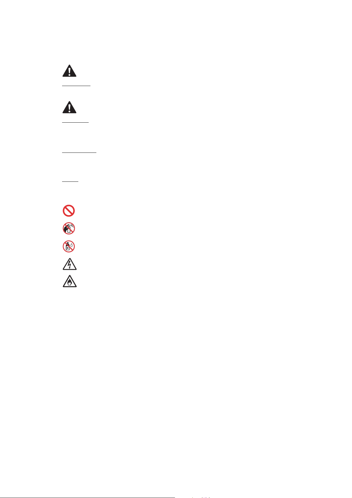
Prohibition icons indicate actions that must not be performed.
This icon indicates that flammable sprays must not be used.
This icon indicates that organic solvents such as alcohol and liquids must not be used.
Electrical Hazard icons alert you to possible electrical shocks.
Fire Hazard icons alert you to the possibility of fire.
Italics
Italicized typeface emphasizes an important point or refers you to a related topic.
Follow all warnings and instructions marked on the machine.
NOTE
The illustrations in this section show the MFC-J880DW.
xiv
Confidential
To use the machine safely
WARNING
ELECTRICAL HAZARDS
Failure to follow the warnings in this section may create the risk of an electrical shock. In
addition, you could create an electrical short, which may create the risk of a fire.
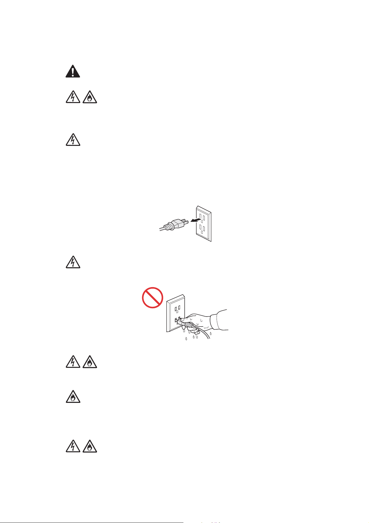
There are high-voltage electrodes inside the machine. Before you access the inside of the
machine, including for routine maintenance such as cleaning, make sure you have unplugged
the power cord from the AC power outlet , as well as any telephone (RJ-11)or Ethernet (RJ-45)
(Models with Wired LAN function only) cables from the machine.
DO NOT push objects of any kind into this machine through slots or openings in the cabinet, as
they may touch dangerous voltage points or short out parts.
DO NOT handle the plug with wet hands.
Always make sure the plug is fully inserted.
Unplug the power plug regularly to clean it. Use a dry cloth to clean the root of the plug blades
and between the blades. If the power plug is plugged into the outlet over a long period, dust
accumulates around the plug blades, which may cause a short circuit resulting in a fire.
DO NOT take apart or convert the machine. This may create a cause of fire or electric shock.
Such conduct may be punished by the law.
xv
Confidential

If the machine has been dropped or the casing has been damaged, there may be the possibility
of an electrical shock. Unplug the product from the AC power outlet.
DO NOT drop any metallic hardware or any type of liquid on the power plug of the machine. It
may cause an electrical shock or a fire.
If water, other liquids, or metal objects get inside the machine, immediately unplug the machine
from the AC power outlet.
This machine should be connected to an AC power source within the range indicated on the
rating label. DO NOT connect it to a DC power source or inverter. If you are not sure what kind
of power source you have, contact a qualified electrician.
Power Cord Safety:
• DO NOT pull on the middle of the AC power cord; pulling on the middle may cause the cord to
separate from the plug. Doing this might cause an electrical shock.
• DO NOT allow anything to rest on the power cord.
• DO NOT place this machine where people can walk on the cord.
• DO NOT place this machine in a position where the cord is stretched or strained, as it may
become worn or frayed.
• DO NOT use the machine or handle the cord if the cord has become worn or frayed. If
unplugging your machine, DO NOT touch the damaged/frayed part.
DO NOT use this product during an electrical storm.
Use caution when installing or modifying telephone lines. Never touch telephone wires or
terminals that are not insulated unless the telephone line has been unplugged at the wall jack.
Never install telephone wiring during a lightning storm. Never install a telephone wall jack in a
wet location.
xvi
Confidential
FIRE HAZARDS
Failure to follow the warnings in this section may create the risk of a fire.
DO NOT use flammable substances, any type of spray or an organic solvent/liquid that contains
alcohol or ammonia to clean the inside or outside of the machine. Doing so could cause a fire or
electrical shock. Instead, use only a dry, lint-free cloth.
DO NOT use the product near any medical electrical equipment. The radio wave emitted from
the product may affect medical electrical equipment and cause a malfunction, which may result
in a medical accident.
For users with pacemakers
This machine generates a weak magnetic field. If you feel anything wrong with the operation of
your pacemakers when near the machine, move away from the machine and consult a doctor
immediately.
If the machine becomes unusually hot, releases smoke, generates any strong smells, or if you
accidentally spill any liquid on it, immediately unplug the product from the AC power outlet.
CAUTION
Wait until pages have exited the machine before picking them up. Failure to do this may cause
injury to your fingers by trapping them in a roller.
DO NOT put your hand or any foreign objects into the ink insertion slot. Doing this may cause
injury.
xvii
Confidential
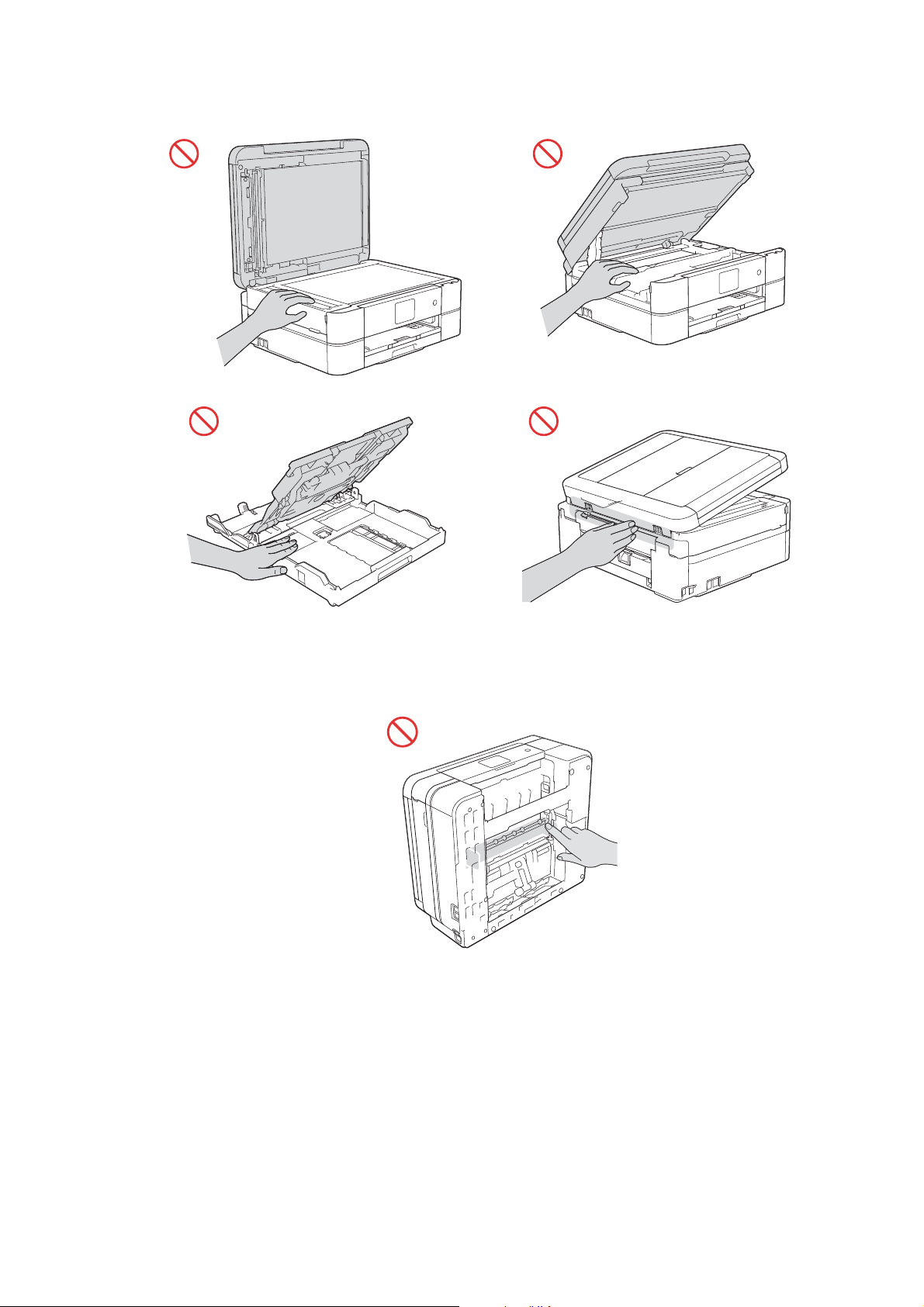
To prevent injuries, be careful not to put your fingers in the areas shown in the illustrations.
DO NOT touch the area shaded in the illustration. Doing this may cause injury to your fingers by
cutting them on the edge of the product.
xviii
Confidential
Do not apply pressure with your hand or elbow in the gray shaded area shown in the illustration
1
below. Doing so may cause the ADF document support (1) to inadvertently open.
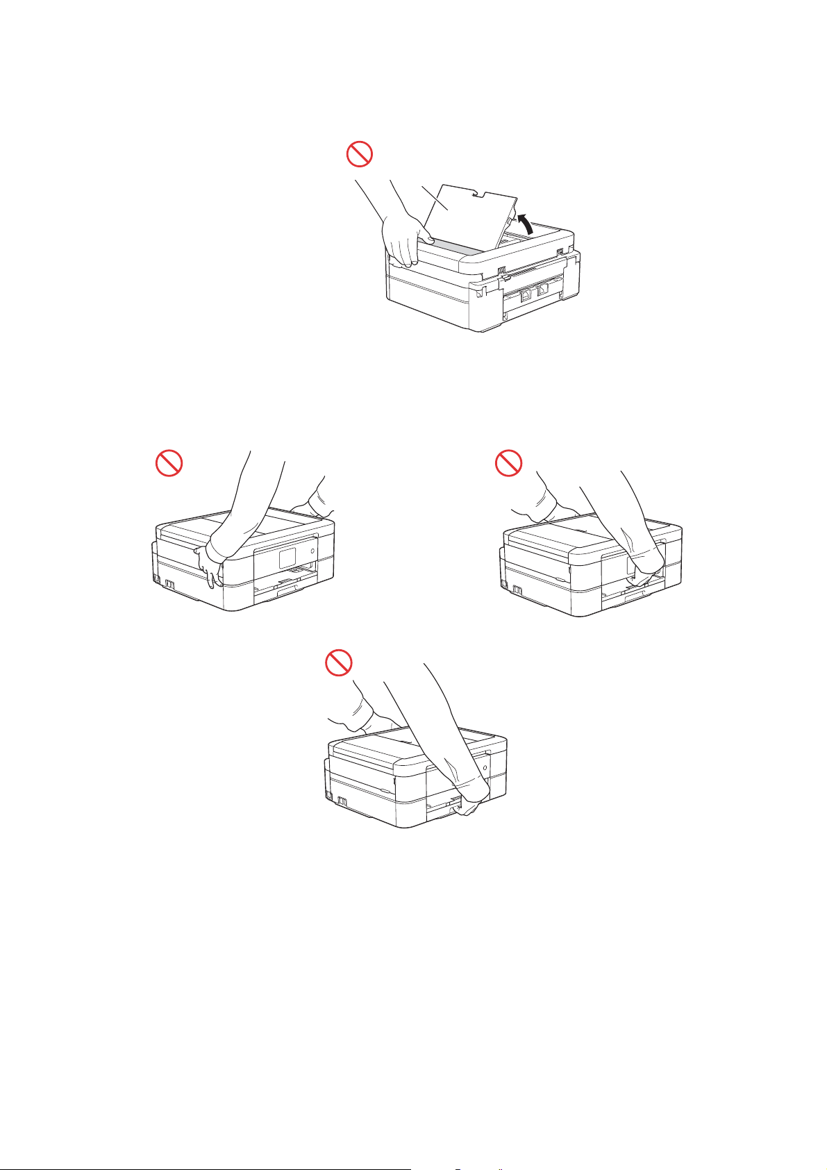
DO NOT carry the product by holding the scanner cover, the Jam Clear Cover, the manual feed
slot cover (some models only), or the control panel. Doing this may cause the product to slip out
of your hands and may result in injury.
xix
Confidential

Only carry the machine by placing your hands under the entire machine.
If the ink contacts your skin or gets into your eye or mouth, please follow these steps
immediately:
• If the ink attaches to your skin, wash it away with water and soap immediately.
• If the ink gets into your eye, rinse it with water immediately. If left as it is, it may cause a red
eye or mild inflammation. In case of any abnormality, consult with your doctor.
• If the ink gets into your mouth, spit it out, rinse your mouth, and consult your doctor
immediately.
• Be careful not to get the ink in your eye when replacing the ink cartridge.
• Keep the ink cartridge out of the reach of children.
• DO NOT shake the ink cartridge hard. The ink may leak out if the cartridge is shaken or
twirled hard.
• DO NOT take apart the ink cartridge. The cartridge cannot be used if it is taken apart. The ink
may get in your eye or make contact with your skin while you take apart the cartridge.
IMPORTANT
• Disruption of power can wipe out information in the machine's memory.
• If the machine does not operate normally when the operating instructions are followed, adjust
only those controls that are covered by the operating instructions. Incorrect adjustment of
other controls may result in damage.
xx
Confidential

Precautions for Troubleshooting and/or Disassembly/Assembly
Be sure to observe the following warnings and precautions to prevent any secondary troubles
from happening by mishandling the machine during troubleshooting and/or disassembly/
assembly.
Precautions
Be sure to observe the following to prevent any secondary troubles from happening during
troubleshooting and/or disassembly/assembly.
(1) Power codes must be removed from their outlets before starting any removal of covers
and PCBs, adjustments and conductivity test using a tester.
(2) Be careful not to lose screws, washers, or other parts.
(3) Apply grease to the points specified in Chapter 3.
(4) When using soldering irons and other heat-generating tools, take care not to damage the
plastic parts such as wires, PCBs, and covers.
(5) When disconnecting the connectors, hold the connector housings. Do not pull the lead wires.
(6) After disconnecting flat cables, check that each cable is not damaged at its end or
shortcircuited.
(7) When connecting flat cables, do not insert them at an angle. After insertion, check again
that the cables are not at an angle.
(8) When connecting or disconnecting harnesses, hold the connector bodies not the cables.
If the connector has a lock, always unlock it.
(9) After repairs, check not only the repaired portion but also that the harnesses are routed
properly. Also check that the other related portions function properly.
(10) Static electricity charged in your body may damage electronic parts.
Before handling the PCBs, touch a metal portion of the machine to discharge static
electricity charged in your body. When transporting PCBs, be sure to wrap them in
conductive sheets.
When replacing the PCBs, put on a grounding wrist band and perform the job on a
conductive mat.
Also take care not to touch the conductor sections on the flat cables.
(11) Once the head/carriage unit prints, it will start head locking operation after five seconds
from the end of printing. The head locking operation will take five to ten seconds. NEVER
unplug the power cord before the machine completes the head locking operation; doing
so will make the head/carriage unit unusable and require replacement with a new head/
carriage unit. When you receive the machine from the user or when you pack it for
sending it back to the user, check the head locking state.
(12) If ink gets on your skin or gets into your eyes or mouth, you need the following treatment.
- If ink gets on your skin, wash it off immediately with soap and water.
- If ink gets into your eyes, flush them immediately and thoroughly with water. If left
untreated, the eyes may become bloodshot or mildly inflamed. If you feel any discomfort,
consult a doctor immediately.
- If ink gets into your mouth, immediately spit it out and consult a doctor.
(13) Be sure to observe the warnings.
(14) After completion of reassembly, it is recommended that the dielectric voltage withstand
test and continuity test be conducted.
(15) After repairing the defective section, be sure to check again if the repaired section works
correctly.
xxi
Confidential
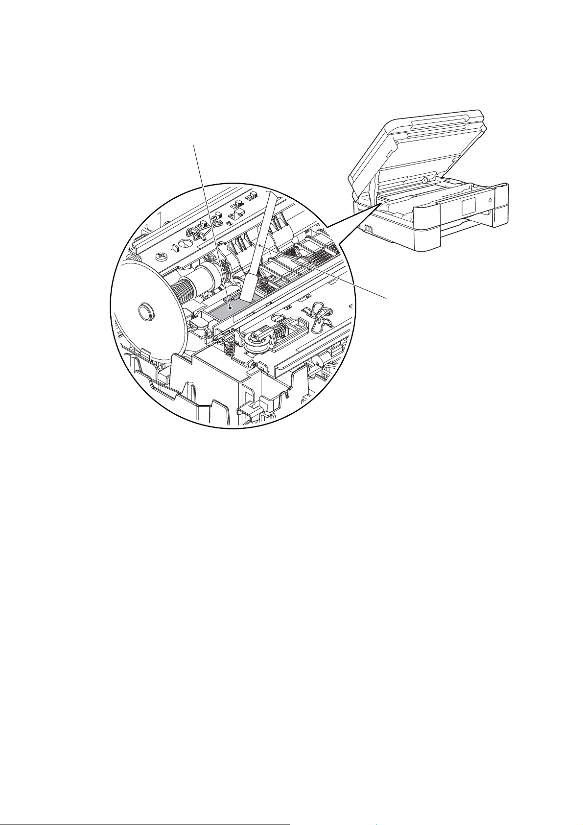
(16) Before packing the machine for sending it back to the user after repairs, be sure to clean
Flushing guide
Cleaner stick
the flushing guide with a cleaner stick as shown below to prevent ink splashing during
transportation.
xxii
Confidential

CHAPTER 1 SPECIFICATIONS
1GENERAL
1.1 General
MFC-J460DW
Model
Print Head
Minimum Droplet Size BK: 3 pl CMY: 1.5 pl
Scanning Method CIS
CPU Speed 288 MHz
Backup Clock Yes (Up to 1 hour)
DCP-J562DW DCP-J785DW
BK/C/M/Y:
210/70/70/70
nozzle
BK/C/M/Y:
210/210/210/
210 nozzle
MFC-J480DW
MFC-J485DW
BK/C/M/Y:
210/70/70/70
nozzle
MFC-J680DW MFC-J775DW
BK/C/M/Y:
210/210/210/
210 nozzle
210/70/70/70
BK/C/M/Y:
nozzle
MFC-J880DW
MFC-J885DW
210/210/210/210 nozzle
MFC-J985DW
BK/C/M/Y:
1-1
Confidential

1.2 Media Specification
Model
Standard Tray
DCP-J562DW DCP-J785DW
A4, LTR, LGL
*1
, EXE, A5, A6, B5*2 (JIS)Photo (102x152 mm/4x6"), Indexcard (127x203 mm/
5x8"), Photo-2L (127x178 mm/5x7"), C5 Envelope, Com-10, DL Envelope, Monarch
Photo (102x152 mm/4x6"),
Photo Tray
Photo-L (89x127 mm/
3.5x5")
A4, LTR, LGL*1, EXE, A5, A6,
*2
(JIS) Photo (102x152
B5
Media
Sizes
Manual Feed Slot
mm/4x6"), Indexcard
(127x203 mm/5x8"), Photo-
2L (127x178 mm/5x7"), C5
Envelope, Com-10, DL
Envelope, Monarch
Photo-L (89x127 mm/3.5x5")
Duplex Print
ADF (width/length)
N/A 148/148 mm to 215.9/355.6 mm (5.8/5.8" to 8.5/14.0")
Scanner Glass
(width/length)
Standard Tray 64-220 g/m
2
(17-58 lb.) N/A
2
(17-79 lb.) N/A
Media
Weights
Photo Tray 64-220 g/m
Manual Feed Slot 64-300 g/m
Duplex Print 64-105 g/m
ADF
N/A 64-90 g/m2 (17-24 lb.)
Standard Tray Plain, Inkjet, Glossy (cast/resin), Recycled
Photo Tray
Plain, Inkjet, Glossy (cast/
resin), Recycled
Media
Types
Manual Feed Slot
Plain, Inkjet, Glossy (cast/
resin), Recycled
Duplex Print Plain, Recycled
ADF
*1
Only for US and Indonesia
*2
Only for China, Hong Kong, Korea and Taiwan
*3
Only for US
N/A Plain, Recycled
MFC-J460DW
MFC-J480DW
MFC-J680DW MFC-J775DW
MFC-J485DW
Photo
(102x152
N/A
mm/4x6"),
Photo-L
N/A
(89x127
mm/3.5x5")
A4, LTR,
*1
, EXE,
LGL
A5, A6, B5
*2
(JIS) Photo
(102x152
mm/4x6"),
Indexcard
(127x203
mm/5x8"),
N/A
Photo-2L
(127x178
N/A
mm/5x7"),
C5
Envelope,
Com-10, DL
Envelope,
Monarch
Photo-L
(89x127
mm/3.5x5")
<PC Print>
A4/LTR/EXE/A5/B5 (JIS)
<Copy>
LTR/EXE
*3
/A4/A5
*2
up to 215.9/297 mm (up to 8.5/11.7")
2
(17-58 lb.)
2
64-220 g/m
(17-58 lb.)
64-300 g/m
(17-79 lb.)
2
2
(17-28 lb.)
N/A 64-220 g/m2 (17-58 lb.)
N/A 64-300 g/m2 (17-79 lb.)
Plain, Inkjet,
N/A
Glossy
(cast/resin),
N/A
Recycled
Plain, Inkjet,
N/A
Glossy
(cast/resin),
N/A
Recycled
MFC-J880DW
MFC-J885DW
MFC-J985DW
Photo (102x152 mm/
4x6"),
Photo-L (89x127 mm/
3.5x5")
*1
A4, LTR, LGL
A6, B5
, EXE, A5,
*2
(JIS) Photo
(102x152 mm/4x6"),
Indexcard (127x203 mm/
5x8"), Photo-2L (127x178
mm/5x7"), C5 Envelope,
Com-10, DL Envelope,
Monarch
Photo-L (89x127 mm/
3.5x5")
Plain, Inkjet, Glossy (cast/
resin), Recycled
Plain, Inkjet, Glossy (cast/
resin), Recycled
1-2
Confidential

1.3 Paper Handling
Model
Standard Tray 100 (80 g/m
Paper Input
(sheets)
Output Paper Capacity
(sheets)
*
For details, refer to Section 10.1 Paper.
Photo Tray 20 (thickness: 0.25 mm)
Manual Feed Slot 1
ADF
DCP-J562DW DCP-J785DW
N/A 20 (80 g/m2)
1.4 LCD Panel
DCP-J562DW DCP-J785DW
LCD
Model
Type & Size 2.7 inch TFT 1.8 inch TFT 2.7 inch TFT 1.8 inch TFT 2.7 inch TFT
Touch-Panel Yes
MFC-J460DW
MFC-J480DW
MFC-J485DW
N/A
N/A 1 N/A 1
MFC-J460DW
MFC-J480DW
MFC-J485DW
N/A Yes N/A Yes
MFC-J680DW MFC-J775DW
2
)
20
(thickness:
0.25 mm)
50 (80 g/m
MFC-J680DW MFC-J775DW
N/A 20 (thickness: 0.25 mm)
2
)
MFC-J880DW
MFC-J885DW
MFC-J880DW
MFC-J885DW
MFC-J985DW
MFC-J985DW
1.5 Memory
Model
Memory Capacity
(physical: Mbytes)
Memory Backup
(with Flash memory)
DCP-J562DW DCP-J785DW
MFC-J460DW
MFC-J480DW
MFC-J485DW
N/A Yes
MFC-J680DW MFC-J775DW
128 MB
MFC-J880DW
MFC-J885DW
MFC-J985DW
1-3
Confidential

1.6 Interface
Model
Host Interface Hi-Speed USB 2.0
LAN
Wireless LAN Yes
PictBridge
USB Memory
Memory Stick Duo
Memory Stick Pro/
Pro Duo/ Micro
Acceptable
Media Cards
(Type & Size)
Media Card
SD Memory Card
(miniSD, microSD
with Adapter)
SDHC Memory Card
(miniSDHC,
microSDHC
with Adapter)
SDXC Memory Card
MultiMedia Card
MultiMedia Card plus
MultiMedia Card
mobile
(with Adapter)
DCP-J562DW DCP-J785DW
N/A Yes N/A Yes N/A Yes
N/A
16 MB-128 MB
(Memory stick is not
available. Duo only)
256 MB-32 GB
(MagicGate: YES if not
use MG function)
(Memory stick Pro is not
available. Pro Duo without
adapter and Micro with
48 GB-
128 GB
128 MB-4 GB N/A
Yes (up to
256 GB)
adapter)
16 MB-2 GB N/A 16 MB-2 GB N/A 16 MB-2 GB
4 GB-32 GB N/A 4 GB-32 GB N/A 4 GB-32 GB
48 GB-
256 GB
32 MB-2 GB N/A 32 MB-2 GB N/A 32 MB-2 GB
64 MB-1 GB N/A
MFC-J460DW
MFC-J480DW
MFC-J485DW
N/A Yes
N/A
N/A
N/A
N/A
MFC-J680DW MFC-J775DW
Yes (up to
256 GB)
16 MB-
128 MB
(Memory
stick is
not
available
. Duo
only)
256 MB-
32 GB
(MagicGate:
YES if not
use MG
function)
(Memory
stick Pro is
not
available.
Pro Duo
without
adapter and
Micro with
adapter)
48 GB-
128 GB
128 MB-
4GB
64 MB-
1GB
MFC-J880DW
MFC-J885DW
N/A Yes (up to 256 GB)
N/A
N/A
N/A
N/A 128 MB-4 GB
N/A 64 MB-1 GB
(Memory stick is not
available. Duo only)
(MagicGate: YES if not
use MG function)
(Memory stick Pro is not
available. Pro Duo without
adapter and Micro with
48 GB-
128 GB
MFC-J985DW
16 MB-128 MB
256 MB-32 GB
adapter)
48 GB-
256 GB
1-4
Confidential
1.7 Others
Model
Operating Environment
Temperature
(Best Print Quality)
Operating Environment
Humidity
(Best Print Quality)
Power
Consumption
(Operating/
Standby/Sleep
mode/Off)
Machine Noise (Operating)
Machine Dimensions
Machine
Weight
U.S.A
Europe
Asia/Oceania
U.S.A
Except for
U.S.A
DCP-J562DW DCP-J785DW
N/A 20/3.5/1.2/0.2 W 20/3.5/1.3/0.2 W
19/3/0.8/
0.2 W
19/3/0.8/
0.2 W
W400 x
D341 x
H151 mm
7.2 kg
(15.9 lb)
19/3.5/1.3/
0.2 W
N/A
W420 x
D341 x
H172 mm
N/A 8.2 kg (18.1 lb)
8.4 kg
(18.5 lb)
MFC-J460DW
MFC-J480DW
MFC-J485DW
10-35 (20-33) degrees centigrade
50-95 (68-91.4) degree fahrenheit
19/3.5/1.1/
0.2 W
19/3.5/1.1/
0.2 W
W400 x D341 x H172 mm
MFC-J680DW MFC-J775DW
20-80 (20-80) %
19/3.5/1.3/
0.2 W
19/3.5/1.3/
0.2 W
50 dBA
8.3 kg (18.3 lb)
MFC-J880DW
MFC-J885DW
N/A 19/3.5/1.3/0.2 W
N/A 19/3.5/1.3/0.2 W
W420 x
D341 x
H172 mm
8.3 kg
(18.3 lb)
N/A
W400 x
D341 x
H172 mm
8.2 kg
(18.1 lb)
8.3 kg
(18.3 lb)
MFC-J985DW
W420 x
D341 x
H172 mm
8.3 kg
(18.3 lb)
8.5 kg
(18.7 lb)
2FAX
MFC-J460DW
Model
Modem Speed (bps) N/A 14,400 (FAX)
Transmission Speed
ITU-T Group
Document
COLOR
FAX
(Send/Receive)
Memory
(Send/Receive)
DCP-J562DW DCP-J785DW
N/A Approx.7 sec (ITU-T Test Chart #1,MMR)
N/A G3
N/A Yes/Yes (ITU-T color FAX)
N/A No/No
MFC-J480DW
MFC-J485DW
MFC-J680DW MFC-J775DW
MFC-J880DW
MFC-J885DW
MFC-J985DW
1-5
Confidential
 Loading...