

Page 1
Page 2

© 1997 Brother Industries Ltd.
Page 3

TaUe of Contents
MFC Setup and i
Connections Caution................................................................................................................1
Paciung List
Choosing a Location.................................................................................... 3
Assembly.................................................................................................. 4
Installing the Ink Cartridges...................................................................... 7
Special Line Considerations.....................................................................10
Multi-Line Connections (PBX).................................................................12
Custom Features on Your Phone Line
Connecting an External
Connecting an External Telephone
.............................................................................................
Make sure you have the following items:
Roll Over Phone Lines...................................................................... 10
TWo-Line Phone System................................................................... 10
Converting Telephone Wall Outlets......................................................10
Installing MFC, External TWo-Line TAD, and 1\vo-Line Telephone
If you are installing the MFC to work with a PBX:
........................................................
Telephone Answering Device (TAD)....................................................... 13
Sequence....................................................................................... 13
Connections....................................................................................14
Outgoing Message (OGM)................................................................. 14
............................................................
.............................................
...........
...............................
2
11
12
13
14
2
Installation „ „
Settings Fax Settings............................................................................................. 17
Setting Dialing Mode (Tone/Pulse)............................................................17
Setting Date and Time............................................................................17
Setting Station ID..................................................................................18
Entering Text....................................................................................... 19
Inserting spaces...............................................................................19
Making correctioas...........................................................................19
Repeating letters..............................................................................19
Special characters and symbols............................................................20
Setting the Answer Mode........................................................................ 20
To select or change your Answer Mode
Setting Ring Delay................................................................................ 22
Setting F/T Ring Time............................................................................22
.............................................
1-7
21
Page 4

Storing One Touch Dial Numbers
.............................................................
23
One Touch Dialing........................................................................... 24
Storing Speed Dial Numbers....................................................................24
Speed Dialing...................................................................................... 25
Changing One Touch and
Speed Dial Numbers............................................................................25
Setting Number Groups for Broadcasting.................................................... 26
Setting Beeper Level..............................................................................27
Memory Storage................................................................................... 27
Distinctive Ringing
...............................................................................
27
Registering the Distinctive Ringing phone number...................................28
Setti^Up
the MIC and
Computer to
Work Together
Before You Begin
Connecting the MFC to Your Computer
Computer Requirements
.....................................................................................
.....................................................
.........................................................................
29
29
30
Installing the Software (CD-ROM 1)..............................................................30
Accessing tlie Software Installation Window
Choosing the Software to Install
All Applications:
.............................................................................
...............................................................
Only PC printing, scanning and document management:
...............................................
...........................
30
32
32
32
Only the MFC drivers:...................................................................... 32
Installing the Applications.......................................................................32
Installing the MFC-7000 Series DOS Tool.................................................. 33
Optional Accessories..................................................................................33
Memory Board..................................................................................... 33
Optional Memory for the Fax Operations............................................... 33
Installing the Optional Memory Board
Compilation and Publication Notices
..................................................
....................................................
34
36
Trademarks.................................................................................... 36
Index......................................................................................................37
For Customer Service................................................................................. 39
Ordering Accessories and Supplies................................................................ 40
Page 5

CHAPTER ONE
MFC Setup and Connections
Caution
^ Never install telephone wiring during a lightning storm.
2 We recommend that this product be used with a surge protection device to
protect the product against lightning storms.
2 Never install a telephone jack in a wet location unless tlie jack is specifically
designed for a wet location.
il’ Never touch telephone wires or terminals that are not iasulated unless the
telephone hne has been disconnected at the network interface.
2 Use caution when installing or modifying telephone lines.
2 Avoid using a telephone (other than a cordless type) during an electrical
storm. There may be a remote risk of electric shock from lightning.
il’ Do not use the telephone to report a gas leak in the vicinity of the leak.
For PLUGGABLE EQUIPMENT, the socket-outlet should be installed near the
equipment and should be easily accessible.
Page 6
CHAPTER ONE
iiiol.................... ifl ■iii>iiii>iiBfl
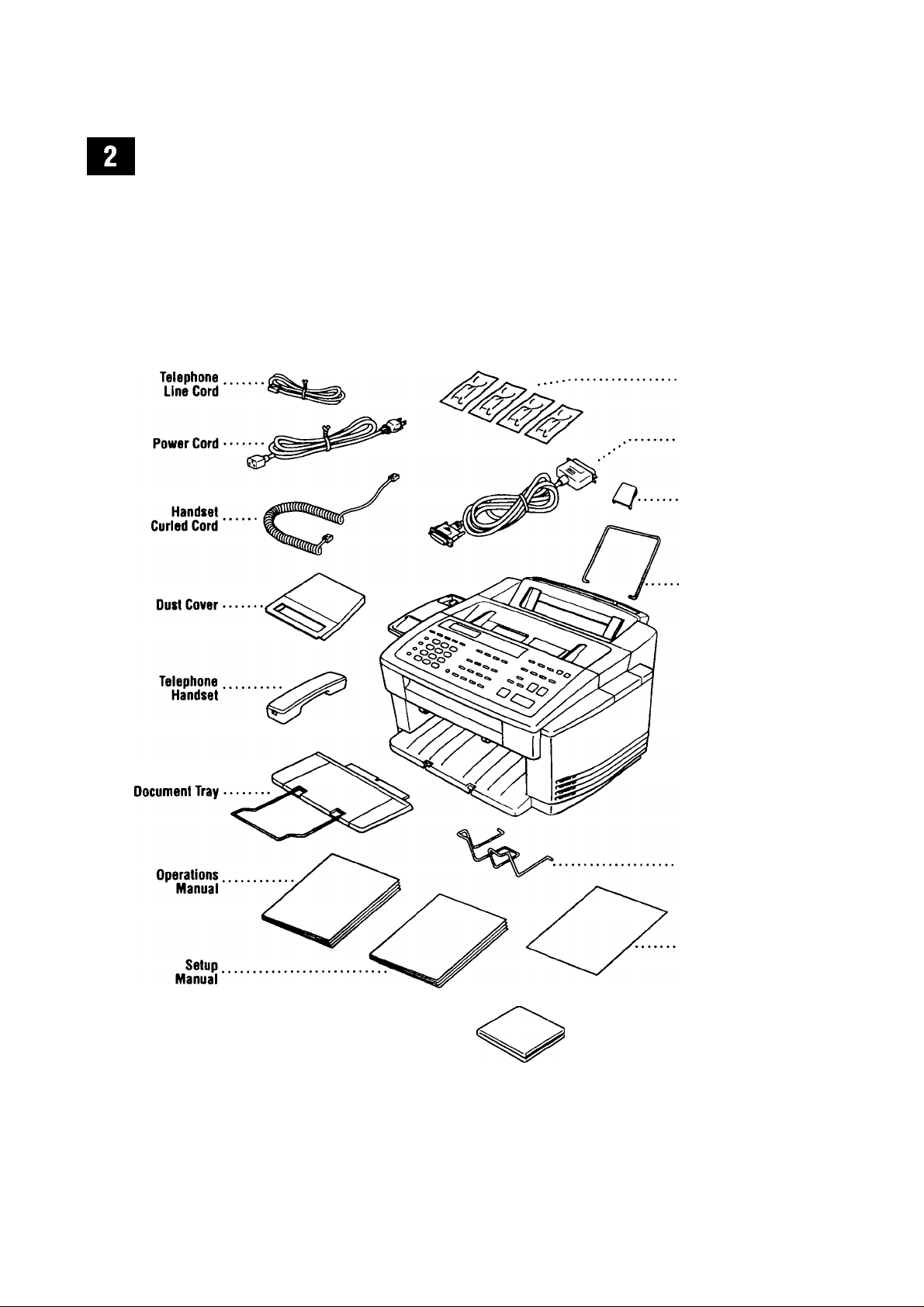
Packing List
Make sure you have the following items:
Ink
Cartridges
Bi-directional
Parallel Cable
Document
Plastic
Extension
Recording
Paper
Wire
Extension
Remote
Control
Access Card
* Starter Coated Paper
(Ink Jet paper)
Recording
Paper
Support
Quick
Reference
Guide
Brother Color
Suite
2 CD-ROMS
* MFC 7200FC has an additional 200 page
cassette tray and Recording Paper Wire
Extension.
Page 7
. M P C"S E T U P AN DC 0 N> EC TI 0 N S
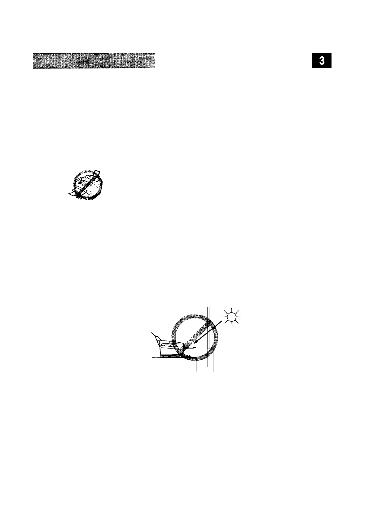
Choosing a Location
Place your MFC on a flat, stable surface, such as a desk. Select a place that is free
of vibration and shocks. Locate the machine near a telephone jack and a
standard, grounded power outlet. Choose a location where the temperature
remains between 50°F and 90°F (10°-35°C).
Avoid placing your MFC in a high-traffic area. Do not place near heaters, air
conditioners, water, chemicals, or refrigerators. Do not expose the machine to
direct sunlight, excessive heat, moisture, or dust. Do not connect your machine to
electrical outlets controlled by wall switches or automatic timers. Disruption of
power can wipe out information in the unit’s memory. Do not connect your
machine to electrical outlets on the same circuit as large appliances or other
equipment that might dismpt the power supply. Avoid interference sources, such
as speakers or the base units of cordless phones.
. ^ atoiS ’
o
Caution
Keep the MFC out of strong light such as direct sunlight, or the unit may not be
able to detect the cartridge ink level.
Page 8
ÍI»'’ CHAFitER ONE -*« ;
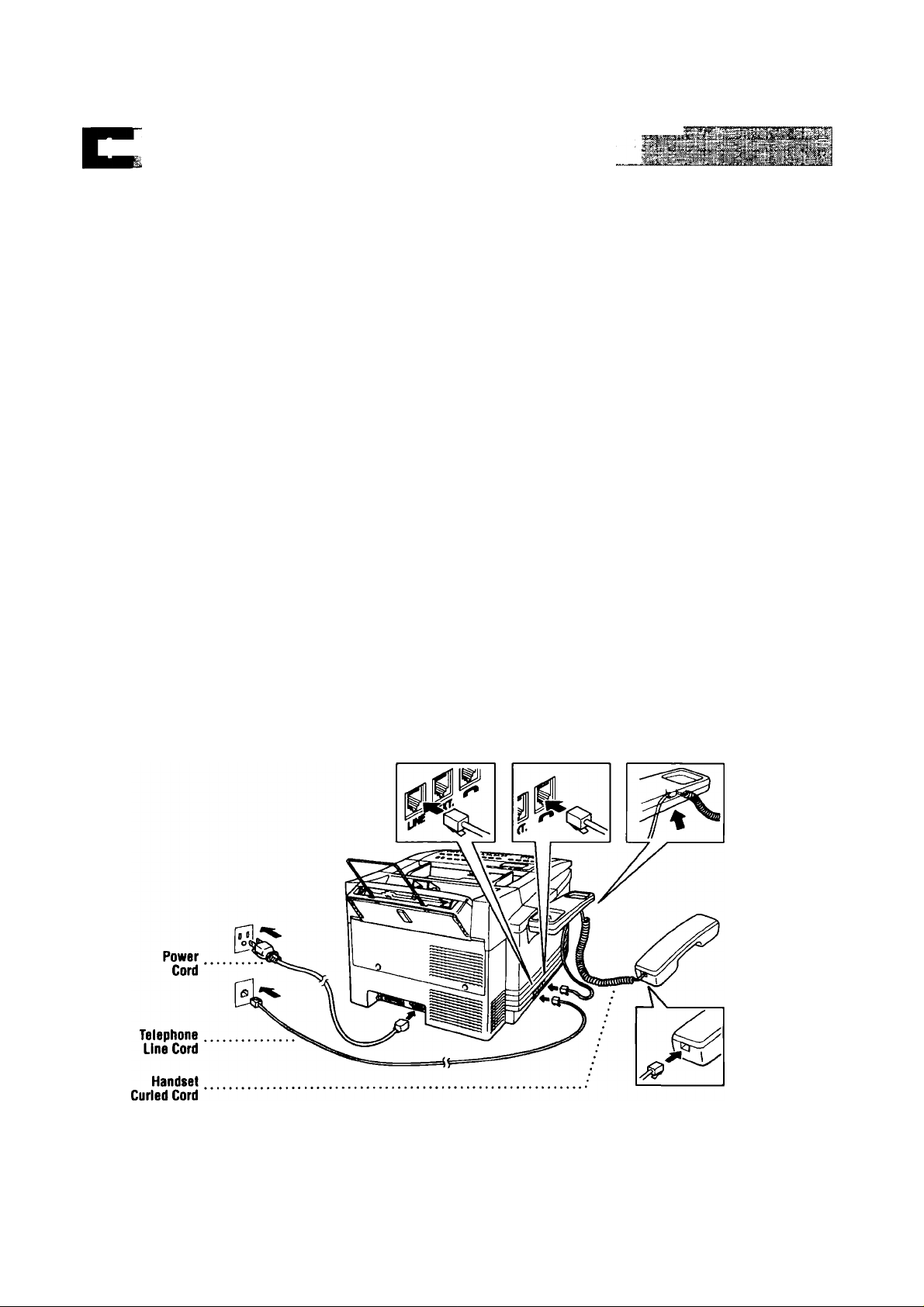
Assembly
H> Connect the handset.
Connect the longer end of the curled handset cord to the MFC and the
shorter end to the handset.
^ Connect the telephone line cord.
Connect one end of the telephone line cord to the jack on the MFC and the
other end to a modular wall jack.
Connect the power cord.
When you connect the power, the screen alternately displays
SET CRRTRIDGES
OFFLINE__________
C
OPEN COMER
OFFLINE
5
o
Caution
Operating the MFC before you install the ink cartridges will
permanently damage the print head.
Page 9
Recording
Paper Wire
Extension
MFC S ET UP
AND
CONNE CT IO NS
NOTE:
1)
The MFC must be grounded using a 3-prong plug.
2) Since the MFC is grounded through the power outlet, you can protect yourself
from potentially hazardous electrical conditions on the telephone network by
keeping the power to your MFC on when you connect it to a telephone line.
Similarly, you can protect yourself when you want to move your MFC, by
disconnecting the telephone line first, and then the power cord.
3) Lightning and power surges can damage this product! We recommend that
you use a quality surge protection device on the AC power line as well as on
the telephone line, or unplug the lines during a lightning storm.
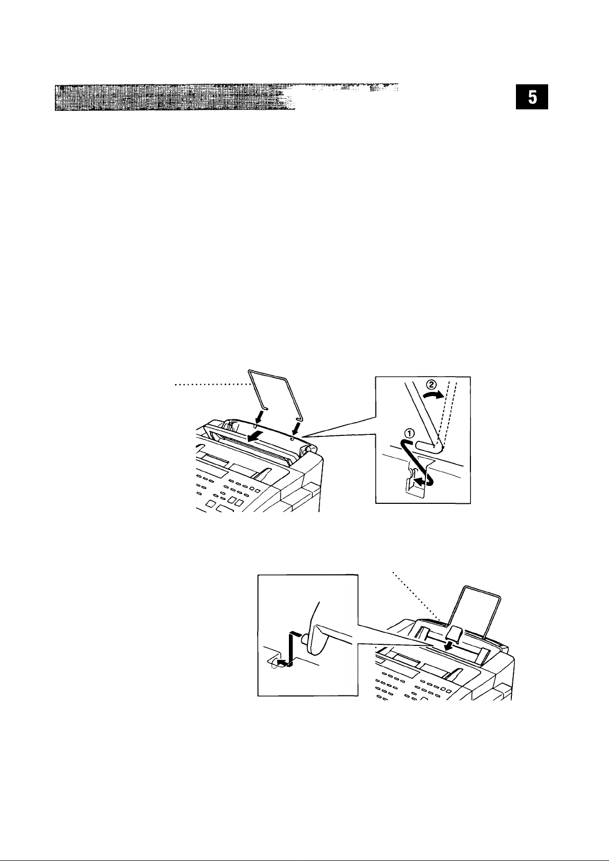
itr Attach the recording paper wire extension to the multi-purpose
sheet feeder.
IS Attach the document plastic extension.
Document
Plastic
Extension
Page 10
C H APT E R’®#M Ey't:-' -i- •' 'i • ■
trf I fci.4ili(Sii 1 rf »1 i||Hl[*iiiiiii I iifu niflffin fi » rt* #
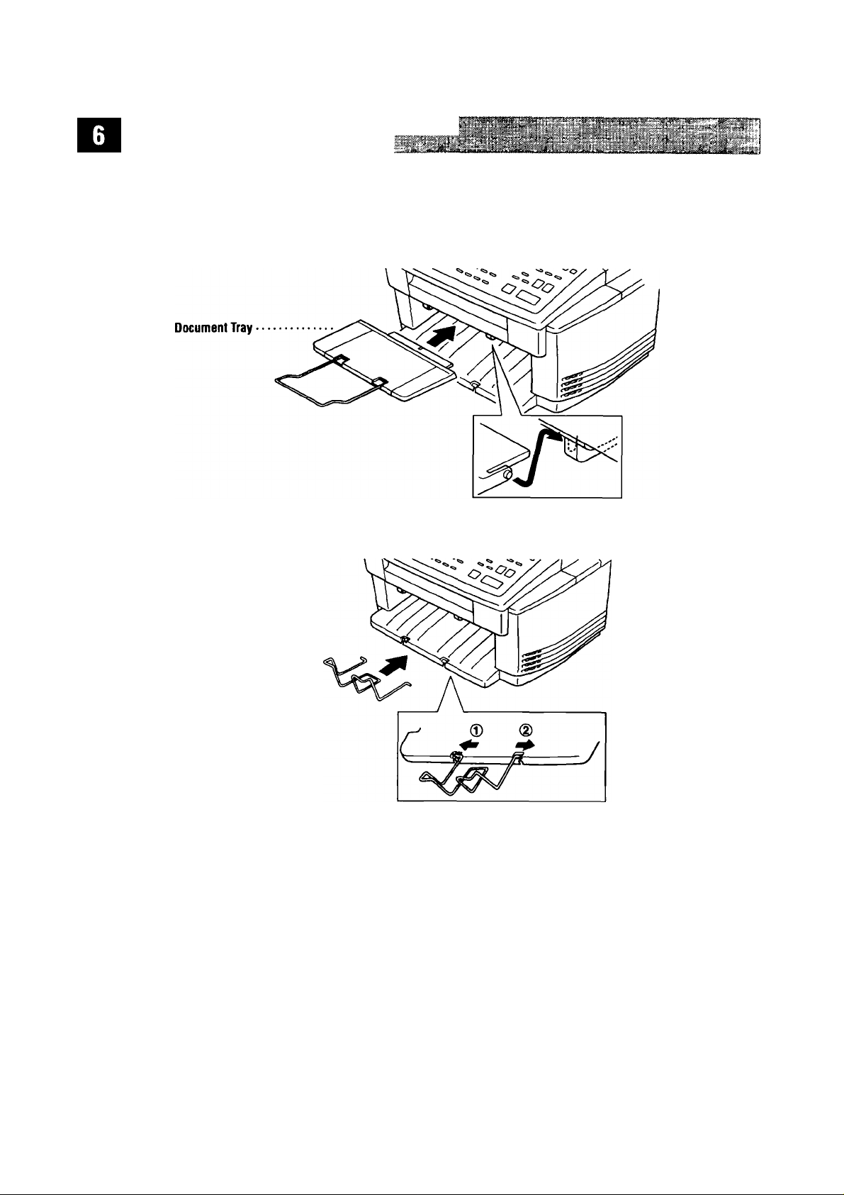
0 Attach the document tray.
Attach the recording paper support to the recording paper tray.
Loading paper in the multi-purpose sheet feeder(Paper
Cassette).
A
Open the multi-purpose sheet feeder cover.
B
Fan the paper well. Load the recording paper. Make sure the
print side is towards you and the paper level is stacked below the line.
C
Adjust the guides to fit the paper.
Page 11

0 Attach the dust cover to the multi-purpose sheet feeder cover.
NOTE:
10
Close the multi-purpose sheet feeder.
■ It is essential to keep the dust cover on your MFC to prevent dust
from entering the print head and causing damage.
■ Using the dust cover on your MFC will prolong the life of the print
head.
Installing the Ink Cartridges___________
0- Be sure that the power is on. The screen alternately displays
SET CARTRIDGES
OFFLINE
C
OPEN COUER
OFFLINE
0 Open the top cover. The print head moves left to its replacement position.
0 Remove the yellow shipping cover by lifting it up and out. The screen di^lays
INSTALL BLACK
We recommend that you install the ink cartridges in this order; Black, Yellow,
Cyan, Magenta
Keep the yellow shipping cover in a safe place. You will need it in the future
when you replace the print head.
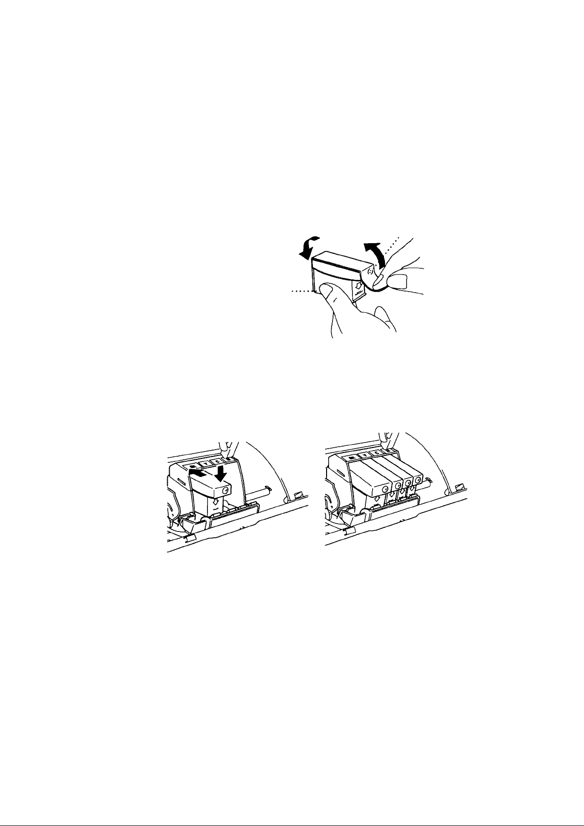
Open the Black ink cartridge bag and remove the ink cartridge.
%
Carefully remove the sealing tape from the side of the ink cartridge. Be sure
to peel the tape from the side of the cartridge in the direction away from you.
Page 12
Important
To prevent spilling ink and staining your hands and clothing, remove the sealing
tape gently and slowly. Do not touch the ink opening on the cartridge or tlie
removed tape.
opening
opening
Each color has its own correct position. Insert the Black ink cartridge,
matching the markings of the color indicators on the print head as a guide.
Push it down until it clicks in place. The line under the arrow should be
aligned with the edge of the cartridge.
As the screen prompts you, repeat Steps 4-7 to install each color ink cartridge.
'%■
After installing all ink cartridges, close the top cover. Your MFC now prepares
for a “head cleaning” and goes online. The MFC will ask you if you changed
each color ink cartridge.
DID YOU CHANGE
BLCK71.YES 2.NO
Page 13

.................
MFC S ET UP AN D C 0 NN E C T JO N S
10
Press Q] on the keypad for each color, as prompted (for initial setup only)
within 1 minute. The MFC will enter a cleaning qcle for approximately five
minutes. The screen alternately displays
WAIT.
The ink dot counter will be set automatically for each color, so the
MFC can warn you with an error message when ink is running low.
Ijoad
paper in the cassette, then press I
When the MFC completes the cleaning cycle, the MFC starts printing the test
sheet.
H Only during initial ink cartridge installation, the screen shows.
CLEANING BLACK
Start
| within 1 minute.
and
PLEASE
A
o
PRINT
I t YES
Check the print quality of the test sheet. If it is not good, clean the print head
again, by pressing [T|. Then press |Stort| within 1 minute.
The MFC starts printing Test Sheet No. 2.
12
Adjust the Vertical Alignment by following the instructions printed on the Test
Print page.
OK?
2.NO
WARNING
If ink gets in your eyes, irrigate them with water immediately and consult a
doctor if you are concerned.
Caution
■ If you pause more than five minutes while inserting the ink cartridges,
the print head will return to the “home” position and the screen will
alternately display SET CARTOIDGES and PRESS INK MANAGE. Press
[Ink
Managementl.
its replacement position again. Continue to install the ink cartridges.
then press [T] on the dial pad. The print head moves left to
■ DO NOT remove ink cartridges if you do not need to replace them. If you
do .so, it may reduce the ink quantity and the MFC will not know the
quantity of ink left in the cartridge.
■ DO NOT shake the ink cartridges. If you do so, the ink may spill when you
take off the sealing tape. If ink staias your body or clothing, wash with
soap or detergent immediately.
Page 14

■ If you install an ink cartridge in the wrong color position, you must clean
the print head several times after correcting the cartridge installation and
before you start printing because the colors were mixed.
■ Once you open an ink cartridge, install it in the MFC and use it up within
six month of installation. Use unopened ink cartridges within two years of
production.
NOTE:
installed the ink cartridges, check and make sure that the ink cartridges are
installed correctly.
Special Line Considerations
If the INK EMPTY error message is on the screen display after you have
____________
Roll Over Phone Lines
A roll over phone system is a group of two or more separate telephone lines that
pass incoming calls to the next available line. The calls are usually passed down
or "rolled over” to the next available phone line in a preset order.
Your MFC can work in a roll over system as long as it is connected to the last
number in the sequence, so the call cannot roll away. Do not put the MFC on any
of the other numbers; when the other lines are busy and a second fax call is
received, the fax call is transferred to a line that does not have a fax machine.
Your MFC will work best on a dedicated line.
Twvo-Line Phone System
A two-line phone system is nothing more than two separate phone numbers on
the same wall outlet. The two phone numbers can be on separate jacks (RJl 1) or
combined into one jack (RJ14). Your MFC must be plugged into an RJll jack.
RJl 1 and RJl4 jacks may be equal in size and appearance and both may contain
4 wires (black, red, green, yellow). To test the type of jack, plug in a
two-line phone and see if it can access both lines. If it can, you must separate the
line for your MFC.
Converting Telephone Wall Outlets
There are three ways to convert to an RJl 1 jack. The first two ways may require
assistance from the telephone company. You can change the wall outlets from one
RJl4 jack to two RJl 1 jacks. Or, you can have an RJl 1 wall outlet installed and
slave or jump one of the phone numbers to it.
Page 15

MFC'S EJ UP AN D CO N NE CT IO NS
The third way is the easiest: Buy a triplex adapter. You can plug a triplex adapter
into an RJl4 outlet. It separates the wires into two separate RJl 1 jacks (Line 1,
Line 2) and a third RJ14 jack (Lines 1 and 2). Plug the MFC into Line 2 of the
triplex adapter.
........................................................rrTTT
RJ14
<
LI L2
lj=LJ=:
RJ11
RJ14
Installing MFC, External TWo-Line TAD,
and TWo-Line Telephone
Triplex Adapter
J r
---
1
L1+L2
when you are installing an
external
two-line telephone answering device (TAD)
and a two-line telephone, your MFC must be isolated on one line at both the wall
jack and at the TAD. The most common connection is to put the MFC on Line 2.
The two-line TAD must have two telephone jacks: one labeled
the other labeled
L2.
You will need at least three telephone line cords, the one
LI
or
L1/L2,
and
that came with your MFC and two for your external two-line TAD. You will need a
fourth line cord if you add a two-line telephone.
Place the two-line TAD and the two-line telephone next to your MFC.
Plug one end of the telephone line cord for your MFC into the
triplex adapter. Plug the other end into the
LINE
jack on the left side of the
L2
jack of the
MFC.
Plug one end of the first telephone line cord for your TAD into the
the triplex adapter. Plug the other end into the
LI
or
L1/L2
LI
jack of
jack of the
two-line TAD.
Plug one end of the second telephone line cord for your TAD into the
of the two-line TAD. Plug the other end into the
EXT.
jack on the left side of
L2
jack
the MFC.
Page 16

Triplex Adapter
L1 L2 L1+L2
□ □ [3
Two Une Phone
□ l1/L2
LJLT
L1 12
External Two Une TAD Fax Machine
u u
Ext Une
You can keep two-line telephones on other wall outlets as always. There are two ways
to add a two-line telephone to the MFC’s wall outlet. You can plug the telephone line
cord from the two-line telephone into the LI -i-L2 jack of the triplex adapter. Or, you
can plug the two-line telephone into the
TEL
jack of the two-line TAD.
Multi-Line Connections (PBX)___________
Most offices use a central telq)hone system. While it is often relatively simple to
connect the machine to a key system or a PBX (Private Branch Exchange), we
suggest that you contact the company that installed your telephone system and ask
them to connect the MFC for you. It is advisable to have a sqjarate line for the MFC.
You can then leave the MFC in FAX Mode to receive faxes any time of day or night
If the MFC is to be connected to a multi-line system, ask your installer to connect
the unit to the last line on the system. This prevents the unit from being activated
each time a telephone call is received.
As with all fax units, this machine must be connected to a two wire system. If your line
has more than two wires, prc^r connection of the MFC cannot be made.
If you are installing the MFC to work with a PBX:
^ It is not guaranteed that the unit will operate correctly under all circum
stances with a PBX. Any cases of difficulty should be reported first to the
company that handles your PBX.
^ If all incoming calls will be aaswered by a switchboard operator, it is
recommended that the Answer Mode be set to
MANUAL.
All incoming calls
should initially be regarded as telephone calls.
^ The unit may be used with either pulse or tone dialing telephone service.
Page 17

MFC S ET UP AN D CO N NE CT IO NS
Custom Features on Your Phone Line
If you have Call Waiting, Ring Master, Voice Mail, an answering service, alarm
system or any other custom feature on your telephone line, it may create a
problem in the operation of your MFC.
Connecting an External
Telephone Answering Device (TAD)
Sequence
Your MFC has a built-in aaswering system, but you might choose to connect an
additional answering system. When you have an
telephone line as the MFC, the TAD answers all calls. The MFC “listens” for fax
calling (CNG) tones. If it hears them, the MFC takes over the call and receives the
fax. If it doesn’t hear CNG tones, the MFC lets the TAD continue playing your
outgoing message so your caller can leave you a voice message.
external
TAD on the same
The TAD must answer within four rings (the recommended setting is two rings).
The MFC cannot hear CNG tones until the TAD has answered the call, and with
four rings there are only 8-10 seconds of CNG tones left for the fax “handshake.”
Make sure you carefully follow instructions in this manual for recording your
outgoing message. Do not use a “toll-saver” ring setting on the TAD.
Do not connect a TAD elsewhere on the same phone line — your MFC and TAD
will both try to control the line.
Page 18

Connections
The external TAD
EJCT. Your MFC cannot work pix^y if you plug the TAD into a wall j ack.
rt*- Plug the telephone line cord from the wall jack into the left side of the MFC,
in the jack labeled IINE.
li Plug the telephone line cord from your external TAD into the left side of the
MFC, in the jack labeled EXT. (Make sure this cord is connected to the TAD
at the TAD’S telephone line jack, and not its telephone set jack.)
3 Set your external TAD to four rings or less. (The MFC’s Ring Delay setting
does not apply).
Set the external TAD to answer calls.
^ Record the outgoing message on your external TAD (see below).
S Set the MFC’s Message Storage to VOICErEXT.
W'-
Press
must
be plugged into the left side
[Model
on the MFC until the FAX and F/T lights are on.
d
the MFC, into the jack labeled
Outgoing Message (OGM)
Timing is important in recording this message.
^ Record five seconds of silence at the beginning of your message. (This allows
your MFC time to listen for the fax CNG tones of automatic transmissions
before they stop.)
Limit your speaking to 20 seconds.
8 End your 20-second message by giving your Remote Activation Code for
people sending manual faxes. For example:
“After the beep, leave a message or send a fax by pressing *51”
Connecting an External Telephone
Your MFC is equipped with a handset that you can use as a regular phone.
However, you can also connect a separate telephone (or telephone answering
device) directly to your MFC.
Connect the modular plug on the telephone’s line cord to the jack labeled EXT.
on the left side of the MFC.
Whenever this phone (or TAD) is in use, the screen displays
and, if the fax handset is lifted, an alarm sounds. To disconnect the call on the
external phone and switch to the fax, press
[Speoker Phonej.
____ ___
EXT. TEL IN USE,
Page 19

MFCJETUP.ANDyCONNBftlONji
The external telephone cannot be used while a function is being performed on the
control panel.
Page 20

CHAPTER ONE
Page 21

CHAPTER TWO
Instdllation
Fax Settings
Setting Dialing Mode (Tone/Pulse)
Your MFC romes set to aa»mmodate tone (multi-frequenq) dialing service. If you
have pulse (rotary) dialing service, you need to change the dialing mode.
Press
iFunctionl.
PULSE
|T),
0,
[D-
The screen prompts you to select
TONE
or
DIRLING:TONE
dirlihg:pulse
# Use 0 or [►] to select dialing mode.
3 Press 0 when the screen displays the dialing mode you want.
It- Press W.
Setting Date and Time
Your MFC displays the date and time, and prints it on every fax you send.
In the event of a power failure, the MFC maintains date and time information for
about one hour. All other settings remain unaffected.
Press [Fundionl.
(T),
(7],
(T).
The screen prompts you to enter the year.
ENTER YERRI^SX
Page 22

GHAPtBR TWO ■
'2 Enter the last two digits of the year. The screen displays your entry, then
prompts you to enter the month.
8 Enter two digits for the month (for example, enter 09 for September, or 10 for
Enter two digits for the day (for example, 06). The screen displays your entry,
then prompts you to set the time.
Enter the time in 24-hour format (for example, enter 15:25 for 3:25 PM).
m
Wait two seconds.
ENTER MONTH; iiX
October). The screen displays your entry, then prompts you to enter the day.
ENTER DflYriiK
ENTER TIME:^X:NN
See
Composing
Electronic
Cover page
in the
Operations
Manual
See
Entering
Text
p. 19
Press S. The screen now displays the date and time you set, and displays it
whenever the MFC is standing by.
Setting Station ID
You can store your name, fax number, and telephone number to be printed on the
fax
Cover Page,
^ Press [Functionl. (T), [t], |T]. The screen prompts you to enter your fax number
2 Enter your fax number (up to 20 digits). The screen displays your entry.
8 Press 0. The screen prompts you to enter your telephone number.
Enter your telephone number (up to 20 digits). If your telephone number
and fax number are the same, enter the same number again.
# Press 1^. The screen prompts you to enter your name or your company name.
and on all fax pages that you send.
FRX:
TEL:
nrme:
Use the keypad to enter your name (up to 20 characters). (You can use the
chart on page 19 to help you enter letters.)
Page 23

c
INSTA LL AT I ON S ET TIN GS
Press 0 to confirm.
Press S. The screen returns to the date and time.
Entering Text ______________________
when you are setting certain functions, such as the Station ID, you may need to
enter text into the MFC. Most number keys have three or four letters printed above
them. The keys for 0, #, and * don’t have printed letters because they are used for
special characters.
By pressing the appropriate number key the correct number of times, you can
access the character you want.
Pre ss Ke y one tim e
0
0
0
0
0
0
0
0
A B
D E
G
J
M N
P
T u V
w
two tim e s
H
K L
Q
X Y
thre e t im es
C
F
I
0
R
four ti me s
S
Z
Inserting spaces
If you want to enter a blank space, press 0 twice.
Making corrections
If you entered a letter incorrectly and want to change it, press 0 to move the
cursor under the last correct letter. Then press [^; all letters to the right of the
cursor are deleted. Re-enter the correct text and/or digits.
Repeating letters
If you need to enter a character assigned to the same key as the previous
character, press 0 to move the cursor to the right.
Page 24

CHAPTER TWO
Special characters and symbols
Press * for (space) !“#$%&‘()* + ,- ./
Press # for ;;< = >? @ [] ^ _
Press 0 for AEOUAg^iO
• --------------------------------------------
:4SiaiA^.^2
NOTE:
The Telephone Consumer Protection Act of 1991 makes it unlawful for
any person to use a computer or electronic device to send any message via a
telephone MFC unless such messages clearly contain, in a margin at the top or
bottom of each transmitted page, or on the first page of the transmission, the date
and time it is sent and an identification of the business or other entity or other
individual sending the message and the telephone number of the sending
machines or such business, other entity, or individual. In order to program this
information into your MFC, you should complete the steps described on page 18
and 19.
■ The telephone number you enter is used only for Call Back Message and
Cover Page features.
■ If you do not enter a fax number, no additional information can be entered.
■ To enter a space, press®.
■ If your Station ID has already been programmed, the screen prompts “ 1” to
make a change, or “2” to exit without changing.
Setting the Answer Mode
The lighted indicators mean: o = not selected, = is selected and lit
See
Distinctive
Ringing
p.27
and
Receiving
Faxes in
Operations
Manual
PR 3638
Manual
—You must answer all calls yourself. If you hear fax tones, press to
begin receiving the fax, then hang ip. You can ase this mode with Distinctive Ringing.
(FAX and F/T lights are off.)
0 FAX
1 MsgCtr
O
FA
FAX
—The MFC automatically answers every call as a fax call. You cannot
receive a voice call, but you can dial out and make a voice call. (Only the FAX
light is on.)
• FAX
I MsgCtr
O FA
Page 25

--^*-TSTr“—— w <m>'m;.
INST ALIATI 0 n S e'T T I N G S
See
For F/T (Fax/
Tel) Mode
Only
in the
Operations
Manual
P.37
See
Flexible
Memory
Settings in
Operations
Manual
P 58
F/T
—The MFC automatically answers every call. If the call is a fax, it prints the
fax. If the call is not a fax, it signals you with a double ring (ring-ring), different
from the phone company ringing, to alert you to pick up the call. If you select this
setting, you’ll need to set the Ring Delay and F/T Ring Time features (on the
following pages). If you have extension phones on the same line as the MFC, set
Ring Delay to 4. (Only the F/T light is on.)
0 FAX
1
MsgCtr
'/c
MSG CTR
—^The MFC provides you with a built-in digital message center for fax
and voice. When you set the MFC to answer calls, it will record up to 99 messages.
For more information about Message Center operation, please see the Operations
Manual. (Both FAX and F/T lights are on.)
• FAX
I MsgCtr
This is the only setting in which you can use an external answering machine
(TAD). Your telephone answering device is connected to your MFC, and answers
every call. Once the external TAD answers, the MFC listens for fax tones. If it
detects fax tones, it prints the fax.
The MFC does not work with telephone company voice mail. F/T Ring Time does
not work in this setting. Ring Delay does not work with an external TAD.
To select or change your Answer Mode
Press |Mode| until the FAX and F/T lights are lit for the answer mode you
want.
Page 26

CHAPTER TWO
See
Operation
from
Extension
Telephone
and
For F/T
(Fax/Tel)
Mode Only
in the
Operations
Manual
PR 36-37
Setting Ring Deiay
The Ring Delay setting determines the number of times the MFC rings before it
answers. If you have extension phones on the same line as the MFC, set the Ring
Delay to 4.
1^- Press
# Press 0 or (T] to select how many times the line rings before the fax
%
14* Press W to exit.
|Fun(tion|.
machine answers (00 - 04). If you select 00, the line doesn’t ring at all.
Press ® when the screen displays your selection.
rn. in. [Tl.
Setting F/T Ring Time
You need to determine how long the MFC will send you its special double ring
when you have a voice call. This ringing happens
the phone company. Only the MFC rings, for 10,20,30, or 60 seconds; no other
phones on the same line ring the special double ring. However, you can answer
the call on any phone on the same line as the Multi-Function Center.
14 Press [Functionl. rn. (Tl. m.
Press 0 or [►] to select how long the MFC will ring to alert you that you
2
have a voice call.
after
the initial ringing from
Press 0 when the screen displays your selection.
RING TiriE:20 SEC
li» Press W to exit.
Now, when a call comes in and the machine is set to F/T Mode, all phones on this
line will ring the number of times you selected in Ring Delay.
You can let the MFC pick up and detect if it’s a fax or voice call. If it’s a fax call,
the MFC prints the fax. If it’s a voice call, the MFC signals you with a double ring
for the length of time you selected in F/T Ring Time.
Even if the caller hangs up during the double ringing, the MFC continues for the
set time. If you don’t pick up during the ring time, the MFC begins sending a fax
tone, even if the caller is still on the line.
Page 27

INSTA LL AT I ON S ET TI NG S
Storing One Touch Dial Numbers
You can store 24 fax/phone numbers that you can dial by pressing one key. You
can also store names with these numbers. When you press a One Touch dial
location, the screen displays the name or number as the call is dialed.
One Touch keys are not the dial pad keys. They are the 12 keys (number
01-24) located to the right of the dial pad. One Ibuch Numbers 13-24 are
accessed by holding doum the Shift button when you press the apporopriate
One Ibuch key.
Press
(Functionl. m. in. m.
# Press the One Touch key where you want to store a number. (Key [T] is
pre-programmed for Brother Fax-Back System (USA only). You can override
it if you wish.) The screen displays the location you selected.
%■
Enter a number (up to 20 digits). If you want to enter a pause in the
dialing sequence (to wait for an “outside line,” for example), press
|Rediol/Pou$e|
pause when the number is dialed, and a dash appears on the screen.
Press The screen prompts you to enter a name for this number.
as you’re entering digits. Pressing
iRedid/Pousel
___ _ __ _ _
enters a 3.5-second
NfiME:
5 Use the keypad to enter the name (up to 15 characters). You can use the
chart on page 19 to help you enter letters—
number without a name.
Press The screen prompts you to select the type of number this is. Use
0or(B to select the type you want.
FAX
TEL
F/T
CHAIN
P- Press W.
# Return to Step 2 to store another One-Touch number—
exit.
When you dial an AUTO DIAL number, the screen displays the name you’ve
stored, or, if you haven’t stored a name, the number you’ve stored.
If you need to store a pause longer than 3.5 seconds, please call Brother Customer
Service at 1-800-284-4329 in the USA, or 1-800-853-6660 from within Canada.
a fax only number
a telephone (voice) number
both a fax and telephone (voice) number
a number (usually an access code) for chain dialing.
OR
—Go to Step 6 to store the
OR
—Press to
Page 28

You can use chain dialing to store long dialing sequences. For example, to store
9 1 201 555 1234 987 65 4321,
the first part as a Chain type number (this tells the system that the dialing
sequence is not complete).
CHAIN —9 1 201 555 1234
The last part of the One-Touch number must be stored as any of the other
following three types.
FAX or F/T or m — 987 65 4321
Now, when you dial, just press the two keys (one after the other, in order) where
you’ve stored the two parts of the number.
If you are using Chain Dialing with a credit card number, do not send an
electronic cover page.
The credit card number will ^pear on it.
divide the number into two parts. Store
One Touch Dialing
Pick up the handset—OR—Press
l2 When you hear a dial tone, press the One Touch key of the location you
want to call.
If you try to use a One Touch location with no number stored in it, you hear a
warning sound, and the screen displays
to normal after two seconds. To see all your numbers, print the All Dial Report
(See Operations Manual, p.ll).
Storing Speed Dial Numbers
You can store Speed Dial numbers, when you dial by pressing only three keys.
MFC 7000FC has 56 Speed Dial locations, and MFC 7200FC has 100. Even if you
lose electrical power, numbers stored in memory will not be lost.
^ Press
[Functionl.
(T|, (T|,
iSpeoker Phone].
NOT REGISTERED.
The display returns
___________
[2].
The screen prompts you to enter a location.
SPEED-DIAL? n_
2 Use the keypad to enter a 2-digit location (01 - 56 or 00). The digits 00
indicate location 100 on the MFC 7200FC. The screen displays your entry,
then prompts you to enter the number you’re storing.
it05
C
ENTER 8i SET
Page 29

: -
' \ o n S
Enter the number (up to 20 digits).
Press 0. The screen now prompts you to store a name with this number.
nrme:
S Use the keypad to enter the name (up to 15 characters). You can use the
chart on page 19 to help you enter letters—
to store the number without a name.
:i^ Press®.
^ The screen prompts you to select the type of number this is. Use 0 or 0 to
select the type you want.
FAX
a fax number
TEL
a telephone (voice) number
F/T
both a fax and telephone number
OR
—Press 0 and go to Step 7
E T T 1 N (i S
CHAIN
¡B‘
Press®.
0
Return to Step 2 to store another Speed Dial number—
exit.
a number (usually an access code) for chain dialing.
OR
—Press ®g) to
Speed Dialing
^ Pick up the handset—OR—Press
>2 When you hear a dial tone, press
Speed Dial number.
ISpe ok er Ph on e |.
[Spe ed D iol |.
then press the two-digit
Changing One Touch and Speed Dial Numbers
If you try to store a One Touch or Speed Dial number in a location where a
number is already stored, the screen displays the current name stored there, then
prompts you to either
1. CHANGE—OR—2. EXIT
Press (T) to change the number stored, or press [T] to exit without making a
change.
2 If you want to erase the number, press jClearj when the cursor is to the far left
of the digits.
3 If you want to change a digit, use (T) or 0 to position the cursor under the
digit you want to change, then enter it.
Page 30

C H A FT ER TW O
Enter a new number.
$ Follow the directions from Step 4 in Storing One Touch Numbers or Storing
Speed Dial Numbers.
Setting Number Groups
for Broadcasting
____________________
See
Storing
One Touch
Dial
Numbers
p.23
and
Storing
Speed Dial
Numbers
p. 24
Number Groups allow you to send the same fax message to many fax numbers by
pressing only one One Touch key (Broadcasting).
fax number as a One Touch or Speed Dial number.
them into a Number Group. Each Number Group uses a One Touch key. Finally,
you can have up to 6 small Number Groups, or you can assign many numbers to
one large group. With MFC 7000FC you can assign up to 79 numbers; with MFC
7200FC, you can assign up to 123 numbers.
^ Press
[Fundionl.
[T|. (T|. (Tl. The screen displays
First,
you’ll need to store each
Then,
you can combine
SELECT ONE-TOUCH
Select a One Touch key where you will store the Group Number. (For
example, press One Touch key (T] for group 2.)
Use the keypad to enter the group number (for example, press (Tj for
group 2).
SETUP GROUP:60
C
ENTER & SET
To include One Touch or Speed Dial numbers in the group, enter them as if
you were dialing. For example, for One Touch key 05, press One Touch key
05. For Speed Dial key 09, press the Speed Dial button, then press 09 on the
dial pad. The LCD shows *05, #09.
G01:+05»09_
3 Press®. The screen prompts you to enter a name.
NAME:
C
ENTER 8: SET
Page 31

JL£LL
"U-i-
;0 Use the keypad and the chart on page 19 to enter a name for the group (for
example, NEW CLIENTS).
# Press (^.
Press M to exit.
You can print a list of all One Touch and Speed Dial numbers. See the Operations
Manual Chapter 2, "Printing Reports and Lists."
Setting Beeper Level
You can set the beeper to
the beeper is set to
make an error, and at the end of fax sending or receiving.
Press [Functionl. m. ill. [T|.
^ Press 0 or (T| to select your setting.
^ When the screen displays the setting you want, press
H* Press W to exit.
LOW, HIGH
LOW
or
HIGH,
or
OFF.
The MFC comes set to
the MFC beeps every time you press a key or
LOW.
When
Memory Storage____________________
All settings in the SET AUTO DIAL, USER OPTIONS, TEL OPTIONS, and SETUP
SYSTEM functions are stored permanently and will be retained even in the event
of a power failure.
Distinctive Ringing
This MFC feature lets you use the Distinctive Ringing subscriber service offered by
some telephone companies, which allows you to have several telephone numbers
on one phone line. Each phone number has its own Distinctive Ringing pattern,
so you know which phone number is ringing. This is one way you can have a
separate phone number for your MFC.
Your MFC has a Distinctive Ringing function, allowing you to dedicate one phone
number to receiving faxes. You’ll need to follow the directions below to “register”
the Distinctive Ringing pattern, so your MFC can recognize its incoming calls.
You will need another person standing by on another line to help you with Step 6
of this registration.
You can change or cancel the Distinctive Ringing pattern at any time. You can
switch it off temporarily, then turn it back on. When you get a new fax number,
make sure you reset this function.
Page 32

- î*v:
CM
AFTER. ,;t w o_ it ::: i: .< ,; : ■ . :: '- ■ ■: ;
You can register only one Distinctive Ringing pattern with the MFC. Some ringing
patterns cannot be registered.
■ The MFC will answer only fax calls to its registered number.
■ To have your Message Center (or external TAD) answer only the main
number, the MFC must be in
■ In F/T Mode or FAX Mode, the MFC will answer all numbers on the phone line.
MANUAL
Mode.
■•* » %* *
«T‘>‘v
»•*-•>?
Registering the Distinctive Ringing phone number
H>- Disconnect the MFC from any TAD or telephone company voice mail. Set the
MFC to
H Have someone ready to call the Distinctive Ringing number
you’re assigning to the MFC.
;3 PressIFunctionl.m.in.fyi.
MANUAL
mode.
H Press (3 or [T] to select the SE'F Mode.
?5 Press®.
0 Press H. The screen displays
D/R SET MODE
ONLINE
Now, another person must call the Distinctive Ringing number.
If you want to exit this programming, press ®). Settings
remain unchanged.
When the MFC rings, listen for the ring pattern, and make sure it’s the one
for the new number for the MFC.
If it is, wait until the screen displays
PICK UP TO SET
ONLINE
0
Lift the MFC handset and press (^. The screen displays
(If the incorrect Distinctive Ringing number was called, press H to
cancel.)
0 Hang up. The Distinctive Ringing feature is now on.
REGISTERED.
Once you’ve registered the Distinctive Ringing number in your MFC, you can turn
this feature
setting, follow steps 1 to 4 above, selecting
ON
or
OFF
without having to reset the number. To change the
ON
or
OFF.
Page 33

CHAPTER THREE
Setting Up
theHti№ai
Comnuter to
Wor
Ipuier to
K Together
and
Before You Begin
"All software is supplied on CD-ROM. If you need a Floppy Diskette version, call Brother at 1-888-879-
3232
and order item # MFC7DSK. (Only MFL Pro, Visioneer PaperPort and 3D FaxSpeed are available
on Floppy Diskette.)"
^
Make sure the IEEE-1284 parallel interface cable is in the package.
Make sure to unplug the MFC power cord from the electrical outlet before
connecting the parallel interface cable.
3 Make sure your computer is off and unplugged from electrical power before
you connect the interface cable.
Connecting the MFC to Your Computer
Connect the interface cable to the parallel interface port on the back of the
MFC, and secure with the wire clips.
2 Connect the interface cable to the printer port of your computer, and secure
with the two screws. (To locate your computer’s printer port, see your
computer user guide.)
1
‘T------1--sr
I c-Oy ^
Page 34

GH APTB R’*THR i E
%
Before plugging the MFC in, plug your computer in and turn it on. Then,
plug in the MFC.
Computer Requirements
The following are the minimum computer requirements you need to set up and
operate the MFC as a printer. Use only a sliielded interface cable that is IEEE
1284 compliant, and that is less than 2 meters (6.5 feet) long.
CPU
RAM
Hard Disk Drive
Operating System
Pentium 75 or higher
SMB or greater for Windows® 3-1 or 3.11
SMB or greater for Windows® 95 (16MB recommended)
50MB CD-ROM 1
250MB CD-ROM 1&2
Windows® 3.1,3-11 or 95
DOS environment compatible with your Windows®
version
______________
Installing the Software (CD-ROM 1)
Accessing the Software Installation Window
When you insert the CD-ROM into the PC with Windows® 95, the screen appears
automatically. (You can also run X:MFC_95.EXE from Explorer.) With
Windows® 3.1 or 3.11, from the File menu, run: X:MFC_31>EXE
__________________________
Page 35

SETTING
U P^T HE
M FC AHD«COMPGTER TO WOR K TOGETHER
■ *£- *Mhk
CCtowBmRCZ
SUITE
SOFTWARE
INSTALLATION CO
C^rrnizri
Lip
m H H W«''ie at )-oat nde-
orocner
Multi-Function Link Pro
PaperPort, Brother Resource Manager, and Brother scanner driver, printer drivers
and True Compatible fonts.
Visioneer PaperPort
(Serial Number: F5JTESFUD3)
3D FaxSpeed
image files so you can fax them to the receiving party’s PC. (The receiving party’s
PC must be able to receive faxes and must have the 3D FaxSpeed Reader
program.)
Online Documentation
on the CD-ROM.
MFC-7000 Series Drivers
driver and the Brother Resource Manager and True Type compatible fonts if you
don’t want all of Multi-Function Link Pro installed on your hard drive. Use this
option if you already have TWain compatible software and if you only want to
print and scan from other Windows® applications.
Maintenance Video
dures: Installing Ink Cartridges, Replacing Ink Cartridges, fixing Document Jams,
regular maintenance, installing memory upgrade, and how to get product
support.
Product Support
Brother Web Link
Web. You must have service with an Internet service provider.
—is the color PC fax software that allows you to convert color
—this is a page of all Brother support numbers.
—Multi-Function Link Pro software, Visioneer
—installs the Visioneer PaperPort Desktop applications.
—includes all online documentation. You can view it
—installs only the Brother printer and scanner
—allows you to view the steps for maintenance proce
—visits the Internet Brother Home Page on the World Wide
Exit
—exits the CD-ROM window.
Page 36

Choosing the Software to Install
The Software Installation screen enables you to load only the software you need. MultiFunction Link Pro includes the PC fax and Visioneer PaperPort applications and the
MFC-7000 Series drivers. However, you can install them sq)arately as needed.
___ __ _ __
All Applications:
If you want to use all of the applicatioas for PC faxing, printing and scanning,
Visioneer PaperPort’s document management and color PC faxing, install
■ MULTI-FUNCTION LINK PRO
■ 3D FaxSpeed
Only PC printing, scanning and document management:
If you are not interested in PC faxing and only want to do PC printing, scanning
and document management, install
■ VISIONEER PAPERPORT
■ MFC-7000 SERIES DRIVERS
Only the MFC drivers:
If you only want to print and scan, you can install only the MFC drivers. Install
■ MFC-7000 SERIES DRIVERS
If you prefer, you can install the MFC driver program directly from the File
Manager or Explorer:
X:DRIVERS\DISKl\SETn]REXE
Installing the Applications
For each application you install, click on that name in the Software Installation
window and follow the instructions on the screen. The last step will be to restart
Windows® and access the Software Installation window again to iastall the next
application.
After you install the MFC-7000 Series drivers, you may see "New Hardware Found
Brother MFC 7000FC" during startup of Windows 95. You can select "Do not
install a driver (Windows will not prompt you again)." and click OK, so
Windows® will not display this dialog again.
Page 37

rf«—
-------
S E TTI N G UP THE M pCfA N D COM PUT ERTO WORK TOGETHER
***
.....
.' j
"T~
-------------------
""T r-
Installing the MF07000 Series DOS Tool
Use these tools only in the DOS environment. You cannot use these tools while
Windows® is running. When you print in DOS mode, select an
(LQ-510, LQ-850, LQ-2550) compatible emulation driver in your application.
Insert the supplied CD-ROM labeled “CD-ROM 1" into your CD-ROM drive.
M- TVpe CD X:\MFLPRO\DISK6\DOSTOOL
S
TVP6
DOSETUP,
then press |Enter|. The main screen appears on your
computer.
H- Make your selection from the list above.
EPSON ESC/P
NOTE:
Before printing, you must set the paper size in this utility
DOS application.
Optional Accessories
Memory Board_____________________
The memory board is installed on the main controller board inside the MFC.
When you add the optional memory board, it increases the performance for fax
operations.
Optional Memory for the Fax Operations
The MFC 7000FC and MFC 7200FC can recognize 1 MB (MEIOOO) or 2MB
(ME2000) of Optional Memory. Be careful to purchase the appropriate memory
board.
and
in your
Additional memory for the fax will expand the memory used for sending and
receiving faxes.
Page 38

.^ CHA PTE R T HRL E, .
■ ^■ - -i»**'!.—ja-ii-----------„ d*
....
, s.ftAA«.
:- - -r> - ■ >- ' V
3*ri *.' r.e5Lii''';v
"f,
' II#*’ *
■ .-’ —-S!'...r ' ■ "
■ f
- - M * - -
~ \
.Model Niune Optional Memon
MFC7000FC 1MB (for Fax)
1 MB(upto tOOpagps) or
2 MB (for Fax)
MFC7200FC
1MB (for Fax)
3 MB (up to 300 pages)
2 MB (for Fax)
2 MB (up to 200 pages)
3 MB (up to 300 pages)
4 MB (up to 400 pages)
or
5 MB (up to 500 pages)
Total
or
or
Installing the Optional Memory Board
#• Unplug the power cord from the AC outlet and disconnect the interface cable.
c2 Remove tlie two screws securing the recording paper tray in the front of the
MFC.
Page 39

---------------------.-,w,..M.-.^.....«;.-----------------------------------------
---------
SEsTTlNG UP THE M F CIA N D SC 0 M P 11# E R TO W 0 R K - T 0 G E T H B R
3 Pull out the recording paper tray.
Hold the edge of the memory board and do not touch its surface. Insert the
memory board in the connector on the Main Board and make sure it is
securely seated.
Return the recording paper tray to its normal position.
'IB"
Secure it with the two screws,
p' Reconnect the interface cable.
’’%■
Plug the power cord into the AC outlet.
Page 40

Compilation and Publication Notice
Under the supervision of Brother Industries Ltd., this manual has been complied
and published, covering the latest product’s descriptions and specifications.
The contents of this manual and the specifications of this product are subject to
change without notice.
Brother reserves the right to make changes without notice in the specifications and
materials contained herein and shall not be responsible for any damages (including
consequential) caused by reliance on the materials presented, including but not
limited to typographical and other errors relating to the publication.
Trademarks________________________
Multi-Function Link Pro is a trademark of Brother Industries, Ltd.
Brother is a registered trademark of Brother Industries, Ltd.
Windows is a registered trademark of Microsoft in the U.S. and other countries.
MS-DOS is a registered trademark of Microsoft in the U.S. and other companies.
3D FaxFile is a registered trademark of Fontech Ltd.
Visioneer Ptq)erPort is a registered trademark of Visioneer, Inc.
Each company whose software title is mentioned in this manual has a Software
License Agreement specific to its proprietary programs.
The brother logo is a registered trademark of Brother Industries, Ltd.
Epson is a registered trademark and LQ-510, LQ-850 and LQ-2550 are trademarks
of Seiko Epson Corporation.
IBM, IBM PC and Proprinter are registered trademarks of International Business
Machines Corporation.
Hammermill copyplus white is a registered trademark of International P^qjer.
All other brand and product names mentioned in this User’s Guide are registered
trademarks of their respective companies.
Page 41

Index
...
Aawer Mode
Assembly
AUTODIAL
................................................................................................
...........................................................................................................
.................................................................................................
12, 20, 21
.........................................
....................................
B
Beeper
...................................................................................................................
Bi-directional Parallel Cable
Broadcasting
..................................
Brother Customer Service
Brother Fax-Back System
...............
..................
...................................................
....................................
..............
.............
............
...................................
C
Call Back Message
Call Waiting
CHAIN
..................................................................................................................
Chain Dialing
Cleaning Cycle
Connecting
..........................................................................
.................................................................................................
............................................................................................
.......................................................................................
.....................................................................................................
Converting Telephone Wall Outlets
Corrections
Cover P^e
Custom Telephone Features
.....................................................................................................
.........................................................................................................
...........................................
...................................
.....................................
...
23, 24, 25
...23, 24, 25
........................................
.....................
....................................
...
.....................................
...
....................................
D
4
23
27
2
26
23
23
20
13
9
13,14
10
19
18, 20, 24
13
Entering Text
Extension Telephone
External Telephone
External TWo-Line TAD
.......................................
... ...........................................................
...................
.........................................................................
.........................................................................
.........................................................................
F
F/T (Fax/Tel) Mode
F/T (Fax/Tel) Ring Time...
FAX
.........................
Fax-Back System
......
..........................
.21,22, 23, 24, 25,28
.....................
.....
.........................................................................
G
Group Number
..................................
.........................................................................
H
Handset
...........................................................
.....................................................................
I
Ink Cartridges
Ink Dot Counter
Inserting Spaces
Installation
Interface Cable
.....................................
.............................
.............................
................................................
............
..................................................
..............................................................................
.........................................................................
.............................
.....................
19
21,22
14
11
21,22
20, 23, 24, 25, 28
23
26
2,4
2, 7, 8,9
9
19
1
29, 30
Date and Time
Dialing Mode
Distinctive Ringing
Document Plastic Extension
Document Tray
Double Ringing
................................
.................................
........................................................................
.........................................
......................................................................................
...................................................................................
.... 17,18,19
....................................
17
....20, 27,28
...............................
...............................
......................
2,5
2,6
21, 22
Jacks
......................................................................
Location
........................................................
J
...........................................................
1
Ij
................................................................................
10,11
3
Page 42

INDEX
M
__
—'
-J~2
-.:. .-v«.-!
—' ' " ------------------"I—7-
---------------
' .V ' .:s
. .
Manual Mode......................................... 20, 28
Memory..................................................3,24
Memory Board
Memory Storage...........................................27
MSGCTR...................................................21
............................................
33
N
Number Groups............................................26
o
OGM......................................................... 14
One Touch Dialing
Packing List..................................................2
Parallel Interface Cable
Pause........................................................
PBXs.........................................................12
Power
......................................
Power Cord................................................ 2,4
Print Head..................................................7,9
Recording Paper Support...............................2, 6
Recording Paper Wire Extension
Remote Activation Code
Ring Delay
Ring Master
Ring Pattern
RJllJack
.....................................................
........................
23, 24, 25, 26
P
..................................
3, 5, 17, 24, 27
R
.....................
................................
.......................................
................................................
................................................
14, 21, 22
29
23
2, 5
14
13
28
10
Roll Over Phone Lines
................................
10
s
Setting Up....................................................1
Special Characters
Speed Dial........................................24, 25, 26
Station ID.........................................18,19, 20
TAD
......................................................13, 21
TEL................................................23, 24,
Telephone Answering Device (TAD)
Telephone Line Cord..................................2,4
Tone/Pulse
Triplex Adapter
T\vo-Line Phone System..............................10
TWo-Line Telephone................................11,12
Voice Mail
Windows® 95
....................................
T
......
11,13,14
...............................................
.........................................
V
...............................................
W
..........................................
19, 20
25
17
11
13
30
Page 43

For Customer Service
USA:
From within Canada: 1-800-853-6660
From within Montreal: 1-514-685-6464
1-800-284-4329
1-908-271-1937 (iax)
1-514-685-4898
(voice)
(voice)
(voice)
(fax)
Page 44

Ordering Accessories and Supplies
For the best quality results use only genuine Brother accessories, available at most
Brother retailers. If you cannot find the accessory you need and you have a Visa,
MasterCard, Discover, or American Express credit card, you can order accessories
directly from Brother.
USA: 1-888-879-3232
1-800-947-1445
From within Canada: 1-800-668-2768
Description Item
Ink Cartridge <black>
Ink Cartridge <cyan>(blue)
Ink Cartridge <magenta>(red)
Ink Cartridge <yellow> LCOIY
360
dpi High Quality Coated Paper
720
dpi High Quality Coated Paper
Glossy Paper
Transparencies
Print Head
1MB Expandable Memory Board
2MB Expandable Memory Board ME2000
Power Protector QPD120
(voice)
(fax)
LCOIBK
LCOIC
LCOIM
BP36CL
BP72CL
BPGLL
BPTRL
HDOOl
MEIOOO
(voice)
MFC-7000 Series Software MFC 7DSK
on floppy disks
(MFL Pro and PaperPort Only)
Brother Coated Paper is InkJet Paper.
Page 45

brother.
Brother International Corporation
200 Cottontail Lane,
Somerset. NJ 08875-6714. U.SA.
Brother International Corporation (Canada) Ltd.
Dollard-des-Ormeaux, QC. CANADA H9B 3H6
These machines are made for use in the USA or CANADA only. We cannot recommend
using them overseas because it may violate the Telecommunications Regulations of that
country and the power requirements of your Multi-Function Center may not be compatible
with the power available in foreign countries. Using USA or CANADA models overseas
Is at your own risk and will void your warranty.
Manufactured by Brother Industries Ltd. whose quality system
is registered by BSI and JQA.
1 rue Hôtel de Ville.
BSI Certificate of registration No. FM27214
JQA Certificate of registration No. JQA-0367
UF9185001©
Printed in Japan
 Loading...