

Page 1

FACSIMILE EQUIPMENT
SERVICE MANUAL
MODEL: FAX2750/FAX-8250P
MFC4350/MFC4650/MFC6650MC/
MFC-9050/MFC-9550
Page 2

© Copyright Brother 1998
All rights reserved.
No part of this publication may be reproduced in any
form or by any means without permission in writing
from the publisher.
Specifications are subject to change without notice.
Page 3

PREFACE
This publication is a Service Manual covering the specifications, construction, theory of operation,
and maintenance of the Brother facsimile equipment. It includes information required for field
troubleshooting and repair--disassembly, reassembly, and lubrication--so that service personnel
will be able to understand equipment function, to rapidly repair the equipment and order any
necessary spare parts.
To perform appropriate maintenance so that the facsimile equipment is always in best condition
for the customer, the service personnel must adequately understand and apply this manual.
This manual is made up of six chapters and appendices.
CHAPTER I. GENERAL DESCRIPTION
CHAPTER II. INSTALLATION
CHAPTER III. THEORY OF OPERATION
CHAPTER IV. DISASSEMBLY/REASSEMBLY AND LUBRICATION
CHAPTER V. MAINTENANCE MODE
CHAPTER VI. ERROR INDICATION AND TROUBLESHOOTING
Appendix 1. EEPROM Customizing Codes
Appendix 2. Circuit Diagrams
This manual describes the models and their versions to be destined for major countries. The specifications
and functions are subject to change depending upon each destination.
Page 4

SAFETY INFORMATION
Laser Safety (110-120V Model only)
This printer is certified as a Class 1 laser product under the US Department of Health and Human
Services (DHHS) Radiation Performance Standard according to the Radiation Control for Health
and Safety Act of 1968. This means that the printer does not produce hazardous laser radiation.
Since radiation emitted inside the printer is completely confined within the protective housings and
external covers, the laser beam cannot escape from the machine during any phase of user
operation.
CDRH Regulations (110-120V Model only)
The Center for Device and Radiological Health (CDRH) of the US Food and Drug Administration
implemented regulations for laser products on August 2, 1976. These regulations apply to laser
products manufactured from August 1, 1976. Compliance is mandatory for products marketed in
the United States. The label shown below indicates compliance with the CDRH regulations and
must be attached to laser products marketed in the United States.
The label for Japanese products
MANUFACTURED: MAY 1998 K
BROTHER INDUSTRIES, LTD.
15-1 Naeshiro-cho, Mizuho-ku, Nagoya 467-8561, Japan.
This product complies with FDA radiation
performance standards, 21 CFR Subchapter J.
Page 5

CHAPTER I.
GENERAL DESCRIPTION
Page 6

CONTENTS
1. EQUIPMENT OUTLINE........................................................................................I-1
1.1External Appearance and Weight..................................................................I-1
1.2Components.................................................................................................I-1
2. SPECIFICATIONS................................................................................................I-2
Page 7
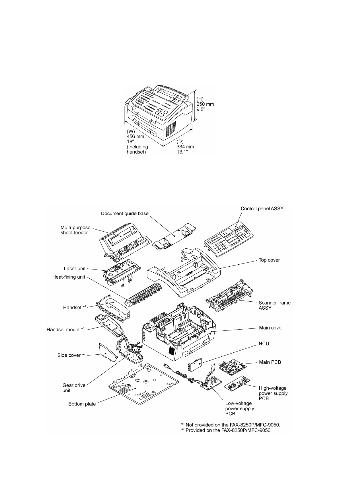
1. EQUIPMENT OUTLINE
1.1 External Appearance and Weight
The figure below shows the equipment appearance and approximate dimensions.
Weight: Machine proper Approx. 7.2 kg
Machine (incl. drum unit & toner cartridge) Approx. 8.5 kg
In package Approx. 12 kg
1.2 Components
The equipment consists of the following major components:
I - 1
Page 8

2. SPECIFICATIONS
Model FAX2750 MFC4350
Color White (1397) White (1138)
PRINTER Available with option *
Engine/Type [YL (VA)] YL (VA)
PPM [6 ppm] 6 ppm
dpi (output resolution) [600 x 600] 600 x 600
Paper Capacity [200] 200
Emulation (Standard) - PCL4
Standards [Windows GDI (600 x 600)] Windows GDI (600 x 600)
Memory (Typical) [1 MB] 1 MB
Memory (Min.) [600 KB] 600 KB
Fonts Resident - Fonts Disk Based [Yes - 35TT] Yes - 4TT
Paper Handling [LTR, LGL, A4, B5, A5, OHP] LTR, LGL, A4, B5, A5, OHP
Multi-Purpose Sheet Feeder [Custom Size (2.75 x 5, 8.5 x 14)
Printer Driver [Windows3.1/3.11, 95 and NT4.0 Driver
Utility Software - RPC
Period to go in Sleep Mode [0-99] 0-99
Output Size [LTR, LGL, A4, B5, A5] LTR, LGL, A4, B5, A5
Optional LAN Board No No
Optional Mac Board No No
Interface/Interface Cable [Yes (Bi Centro)/No] Yes (Bi Centro)/Yes
SCANNER Available with option *
Color/Mono [Mono] [Mono]
dpi [OPT 200 x 400 (600 x 600)] [OPT 200 x 400 (600 x 600)]
Gray Scale [256] [256]
Twain [Yes] [Yes]
Formats (Import) [TIFF/BMP/PCX/DCX/BTF/ BTX/MAX/PDF] [TIFF/BMP/PCX/DCX/BTF/ BTX/MAX/PDF]
Formats (Export) [TIFF/BMP/MAX/PDF] [TIFF/BMP/MAX/PDF]
ADF (pages) [20] *
OCR [Xerox Textbridge] [Xerox Textbridge]
COPY Yes Yes
dpi 203 x 391 203 x 391
Collating 99 99
Reduction/Enlargement 50, 75, 87, 93, 100, 120, 125, 150, 200% 50, 75, 87, 93, 100, 120, 125, 150, 200%
Sorting Yes Yes
FAX Yes Yes
Modem/Speed (bps) Toshiba 3080 (14.4K FAX Only) Toshiba 3080 (14.4K FAX Only)
CCITT Group G3 G3
Coding Method MH/MR/MMR MH/MR/MMR
Error Correction Mode (ECM) Yes Yes
Transmission Speed (sec) 6 6
Gray Scale 64 64
Super Fine Yes Yes
Smoothing Yes Yes
Multi-Resolution TX Yes Yes
Input/Output Width 8.5" x 8.5" 8.5" x 8.5"
LCD Size 16 x 1 16 x 2
Handset Yes Yes
Duplex Speaker Phone No No
*1 Optional CD-ROM required.
*2 30 pages under the following conditions: - Temperature: 20°C to 30°C - RH: 50% to 70%
Specifications enclosed in brackets are available if options are used.
Envelop (DL/C5/CM10/Mona)]
with Auto Installer Program]
- Forms type: Xerox 4200 (20 lb/LTR), Xerox 4024 (24 lb/LTR), M.PPC (64 g/m2/A4)
- Loading as shown at right.
(Loading more than 20 pages in any
other way will result in a double feed
or paper jam.)
1
Custom Size (2.75 x 5, 8.5 x 14)
Envelop (DL/C5/CM10/Mona)
Windows3.1/3.11, 95 and NT4.0 Driver
with Auto Installer Program
1
2
Available with option *
Yes
[20] *
1
2
(1/2)
I - 2
Page 9

Model MFC4650 MFC6650MC
Color White (1138) White (1138)
PRINTER Yes Yes
Engine/Type YL (VA) YL (VA)
PPM 6 ppm 6 ppm
dpi (output resolution) 600 x 600 600 x 600
Paper Capacity 200 200
Emulation (Standard) PCL4 PCL4
Standards Windows GDI (600 x 600) Windows GDI (600 x 600)
Memory (Typical) 1 MB 1 MB
Memory (Min.) 600 KB 600 KB
Fonts Resident - 24 bitMAP (PCL4Comp)
Fonts Disk Based Yes - 35TT Yes - 35TT
Paper Handling LTR, LGL, A4, B5, A5, OHP LTR, LGL, A4, B5, A5, OHP
Multi-Purpose Sheet Feeder Custom Size (2.75 x 5, 8.5 x 14)
Printer Driver Windows3.1/3.11, 95 and NT4.0 Driver with Auto
Envelop (DL/C5/CM10/Mona)
Installer Program
Custom Size (2.75 x 5, 8.5 x 14)
Envelop (DL/C5/CM10/Mona)
Windows3.1/3.11, 95 and NT4.0 Driver with Auto
Installer Program
Utility Software RPC RPC
Period to go in Sleep Mode 0-99 0-99
Output Size LTR, LGL, A4, B5, A5 LTR, LGL, A4, B5, A5
Optional LAN Board No No
Optional Mac Board No No
Interface/Interface Cable Yes (Bi Centro)/Yes Yes (Bi Centro)/Yes
SCANNER Yes Yes
Color/Mono Mono Mono
dpi OPT 200 x 400 (600 x 600) OPT 200 x 400 (600 x 600)
Gray Scale 256 256
Twain Yes Yes
Formats (Import) TIFF/BMP/PCX/DCX/BTF/ BTX/MAX/PDF TIFF/BMP/PCX/DCX/BTF/ BTX/MAX/PDF
Formats (Export) TIFF/BMP/MAX/PDF TIFF/BMP/MAX/PDF
ADF (pages) 20 *
2
20 *
2
OCR Yes (Xerox Textbridge) Yes (Xerox Textbridge)
COPY Yes Yes
dpi 203 x 391 203 x 391
Collating 99 99
Reduction/Enlargement 50, 75, 87, 93, 100, 120, 125, 150, 200% 50, 75, 87, 93, 100, 120, 125, 150, 200%
Sorting Yes Yes
FAX Yes Yes
Modem/Speed (bps) Toshiba 3080 (14.4K FAX Only) Toshiba 3080 (14.4K FAX Only)
CCITT Group G3 G3
Coding Method MH/MR/MMR MH/MR/MMR
Error Correction Mode (ECM) Yes Yes
Transmission Speed (sec) 6 6
Gray Scale 64 64
Super Fine Yes Yes
Smoothing Yes Yes
Multi-Resolution TX Yes Yes
Input/Output Width 8.5" x 8.5" 8.5" x 8.5"
LCD Size 16 x 2 16 x 2
Handset Yes Yes
Duplex Speaker Phone No No
*1 Optional CD-ROM required.
*2 30 pages under the following conditions: - Temperature: 20°C to 30°C - RH: 50% to 70%
- Forms type: Xerox 4200 (20 lb/LTR), Xerox 4024 (24 lb/LTR), M.PPC (64 g/m2/A4)
- Loading as shown at right.
(Loading more than 20 pages in any
other way will result in a double feed
or paper jam.)
Specifications enclosed in brackets are available if options are used.
(1/2)
I - 3
Page 10

Model FAX-8250P MFC-9050
Color White (1397) White (1138)
PRINTER Available with option *
1
Yes
Engine/Type [YL (VA)] YL (VA)
PPM [6 ppm] 6 ppm
dpi (output resolution) [600 x 600] 600 x 600
Paper Capacity [200] 200
Emulation (Standard) - Standards [Windows GDI (600 x 600)] Windows GDI (600 x 600)
Memory (Typical) [1 MB] 1 MB
Memory (Min.) [600 KB] 600 KB
Fonts Resident - Fonts Disk Based [Yes - 35TT] Paper Handling [LTR, LGL, A4, B5, A5, OHP] LTR, LGL, A4, B5, A5, OHP
Multi-Purpose Sheet Feeder [Custom Size (2.75 x 5, 8.5 x 14)
Printer Driver [Available with option (Windows3.1/3.11, 95 and
Envelop (DL/C5/CM10/Mona)]
NT4.0 Driver with Auto Installer Program)]
Custom Size (2.75 x 5, 8.5 x 14)
Envelop (DL/C5/CM10/Mona)
Windows3.1/3.11, 95 and NT4.0 Driver with Auto
Installer Program
Utility Software - Period to go in Sleep Mode [0-99] 0-99
Output Size [LTR, LGL, A4, B5, A5] LTR, LGL, A4, B5, A5
Optional LAN Board No No
Optional Mac Board No No
Interface
Interface Cable
SCANNER Available with option *
[Yes (Bi Centro)
No]
Yes (Bi Centro)
1
Yes <Germany version only>
Available with option *
1
Color/Mono [Mono] [Mono]
dpi [OPT 200 x 400 (600 x 600)] [OPT 200 x 400 (600 x 600)]
Gray Scale [256] [256]
Twain [Yes] [Yes]
Formats (Import) [TIFF/BMP/PCX/DCX/BTF/ BTX/MAX/PDF] [TIFF/BMP/PCX/DCX/BTF/ BTX/MAX/PDF]
Formats (Export) [TIFF/BMP/MAX/PDF] [TIFF/BMP/MAX/PDF]
ADF (pages) [20] *
2
[20] *
2
OCR [Xerox Textbridge] [Xerox Textbridge]
COPY Yes Yes
dpi 203 x 391 203 x 391
Collating 99 99
Reduction/Enlargement 50, 75, 87, 93, 100, 120, 125, 150, 200% 50, 75, 87, 93, 100, 120, 125, 150, 200%
Sorting Yes Yes
FAX Yes Yes
Modem/Speed (bps) Toshiba 3080 (14.4K FAX Only) Toshiba 3080 (14.4K FAX Only)
CCITT Group G3 G3
Coding Method MH/MR/MMR MH/MR/MMR
Error Correction Mode (ECM) Yes Yes
Transmission Speed (sec) 6 6
Gray Scale 64 64
Super Fine Yes Yes
Smoothing Yes Yes
Multi-Resolution TX Yes Yes
Input/Output Width 8.5" x 8.5" 8.5" x 8.5"
LCD Size 16 x 1 16 x 2
Handset No No
Duplex Speaker Phone No No
*1 Optional CD-ROM required.
*2 30 pages under the following conditions: - Temperature: 20°C to 30°C - RH: 50% to 70%
- Forms type: Xerox 4200 (20 lb/LTR), Xerox 4024 (24 lb/LTR), M.PPC (64 g/m2/A4)
- Loading as shown at right.
(Loading more than 20 pages in any
other way will result in a double feed
or paper jam.)
Specifications enclosed in brackets are available if options are used.
(1/2)
I - 4
Page 11

(1/2)
Model MFC-9550
Color White (1138)
PRINTER Yes
Engine/Type YL (VA)
PPM 6 ppm
dpi (output resolution) 600 x 600
Paper Capacity 200
Emulation (Standard) PCL4
Standards Windows GDI (600 x 600)
Memory (Typical) 1 MB
Memory (Min.) 600 KB
Fonts Resident 24 bitMAP (PCL4Comp)
Fonts Disk Based Yes - 35TT
Paper Handling LTR, LGL, A4, B5, A5, OHP
Multi-Purpose Sheet Feeder Custom Size (2.75 x 5, 8.5 x 14)
Printer Driver Windows3.1/3.11, 95 and NT4.0 Driver with Auto
Utility Software RPC
Period to go in Sleep Mode 0-99
Output Size LTR, LGL, A4, B5, A5
Optional LAN Board No
Optional Mac Board No
Interface
Interface Cable
SCANNER Yes
Color/Mono Mono
dpi OPT 200 x 400 (600 x 600)
Gray Scale 256
Twain Yes
Formats (Import) TIFF/BMP/PCX/DCX/BTF/ BTX/MAX/PDF
Formats (Export) TIFF/BMP/MAX/PDF
ADF (pages) 20 *
OCR Yes (Xerox Textbridge)
COPY Yes
dpi 203 x 391
Collating 99
Reduction/Enlargement 50, 75, 87, 93, 100, 120, 125, 150, 200%
Sorting Yes
FAX Yes
Modem/Speed (bps) Toshiba 3080 (14.4K FAX Only)
CCITT Group G3
Coding Method MH/MR/MMR
Error Correction Mode (ECM) Yes
Transmission Speed (sec) 6
Gray Scale 64
Super Fine Yes
Smoothing Yes
Multi-Resolution TX Yes
Input/Output Width 8.5" x 8.5"
LCD Size 16 x 2
Handset Yes
Duplex Speaker Phone No
*1 Optional CD-ROM required.
*2 30 pages under the following conditions: - Temperature: 20°C to 30°C - RH: 50% to 70%
Specifications enclosed in brackets are available if options are used.
Envelop (DL/C5/CM10/Mona)
Installer Program
Yes (Bi Centro)
Yes <Germany version only>
2
- Forms type: Xerox 4200 (20 lb/LTR), Xerox 4024 (24 lb/LTR), M.PPC (64 g/m2/A4)
- Loading as shown at right.
(Loading more than 20 pages in any
other way will result in a double feed
or paper jam.)
I - 5
Page 12

Model FAX2750 MFC4350
One-touch Dial 12 x 2 12 x 2
Speed Dial 100 100
Tel-Index Yes Yes
Chain Dialing Yes Yes
Contrast SL/Auto/SD SL/Auto/SD
FAX/TEL Switch Yes Yes
Distinctive Ringing Yes Yes
Caller ID Yes (Call Waiting) Yes (Call Waiting)
TAD Interface Yes Yes
Next FAX Reservation Yes, Dual Access Yes, Dual Access
Dual Access Yes Yes
Help Yes Yes
Coverpage Yes, Super Yes, Super
Polling Type Std/Seq Std/Seq
Password Check No No
Delayed Timer Yes, up to 50 Yes, up to 50
Broadcasting Yes, up to 174 Yes, up to 174
Call Reservation Yes Yes
Page Memory (TX) *
Out-of-paper Reception *
3
3
Max 1.3 MB (130 pages: MMR) Max 1.3 MB (130 pages: MMR)
Max 1.3 MB (130 pages: MMR) Max 1.3 MB (130 pages: MMR)
Callback Message Yes Yes
Super Quickscan Yes Yes
Mail box No No
Multi-Transmission No No
Message Center No No
OGM No No
ICM Recording Time No No
Paging Yes Yes
Toll Saver No No
Fax & Voice Mail Box No No
Fax- & Voice-on-Demand No No
FAX Forwarding Yes Yes
FAX Retrieval Yes Yes
General
Energy Star Compliance Yes Yes
Memory (Standard) 2 MB 2 MB
Memory (Opt Upgrade) 1/2 MB 1/2 MB
Simultaneous Operation Available with option *
(PRINTER/FAX, PRINTER/SCAN,
PRINTER/COPY)
1
Yes (PRINTER/FAX, PRINTER/COPY)
Available with option *
(PRINTER/SCAN)
Data Modem No No
Bundled Software Applications Available with option *
1
Available with option *
PC-FAX (Send/Receive) [SMSI] [SMSI]
Scanner Application [Brother] [Brother]
Viewer Application [Visioneer] [Visioneer]
Network Application No No
Class 1 No No
*1 Optional CD-ROM required.
*3 According to the Brother chart in standard mode, MMR.
Specifications enclosed in brackets are available if options are used.
(2/2)
1
1
I - 6
Page 13

Model MFC4650 MFC6650MC
One-touch Dial 12 x 2 12 x 2
Speed Dial 100 100
Tel-Index Yes Yes
Chain Dialing Yes Yes
Contrast SL/Auto/SD SL/Auto/SD
FAX/TEL Switch Yes Yes
Distinctive Ringing Yes Yes
Caller ID Yes (Call Waiting) Yes (Call Waiting)
TAD Interface Yes Yes
Next FAX Reservation Yes, Dual Access Yes, Dual Access
Dual Access Yes Yes
Help Yes Yes
Coverpage Yes, Super Yes, Super
Polling Type Std/Seq Std/Seq
Password Check No No
Delayed Timer Yes, up to 50 Yes, up to 50
Broadcasting Yes, up to 174 Yes, up to 174
Call Reservation Yes Yes
Page Memory (TX) *
Out-of-paper Reception *
3
3
Max 1.3 MB (130 pages: MMR) Max 1.3 MB (130 pages: MMR)
Max 1.3 MB (130 pages: MMR) Max 1.3 MB (130 pages: MMR)
Callback Message Yes Yes
Super Quickscan Yes Yes
Mail box No No
Multi-Transmission No No
Message Center No Yes (Hardware)
OGM No Yes (Hardware)
ICM Recording Time No Hardware: 20 min.
Paging Yes Yes (Hardware)
Toll Saver No Yes (Hardware)
Fax & Voice Mail Box No No
Fax- & Voice-on-Demand No No
FAX Forwarding Yes Yes
FAX Retrieval Yes Yes
General
Energy Star Compliance Yes Yes
Memory (Standard) 2 MB 2 MB
Memory (Opt Upgrade) 1/2 MB 1/2 MB
Simultaneous Operation Yes (PRINTER/FAX, PRINTER/SCAN,
PRINTER/COPY)
Yes (PRINTER/FAX, PRINTER/SCAN,
PRINTER/COPY)
Data Modem No No
Bundled Software Applications Yes Yes
PC-FAX (Send/Receive) SMSI SMSI
Scanner Application Brother Brother
Viewer Application Visioneer Visioneer
Class 1 No Yes
*1 Optional CD-ROM required.
*3 According to the Brother chart in standard mode, MMR.
Specifications enclosed in brackets are available if options are used.
(2/2)
I - 7
Page 14

Model FAX-8250P MFC-9050
One-touch Dial 12 x 2 12 x 2
Speed Dial 100 100
Tel-Index Yes Yes
Chain Dialing Yes Yes
Contrast SL/Auto/SD SL/Auto/SD
FAX/TEL Switch Yes Yes
Distinctive Ringing Yes (Denmark version only) Yes (Denmark version only)
Caller ID Yes (U.K. French/Norway/Sweden versions only) Yes (U.K. French/Norway/Sweden versions only)
TAD Interface Yes Yes
Next FAX Reservation Yes, Dual Access Yes, Dual Access
Dual Access Yes Yes
Help Yes Yes
Coverpage Yes, Super Yes, Super
Polling Type Std/Seq/Sec Std/Seq/Sec
Password Check No No
Delayed Timer Yes, up to 50 Yes, up to 50
Broadcasting Yes, up to 174 Yes, up to 174
Call Reservation Yes Yes
Page Memory (TX) *
Out-of-paper Reception *
3
3
Max 1.3 MB (130 pages: MMR) Max 1.3 MB (130 pages: MMR)
Max 1.3 MB (130 pages: MMR) Max 1.3 MB (130 pages: MMR)
Callback Message Yes Yes
Super Quickscan No No
Mail box No No
Multi-Transmission No No
Message Center No No
OGM No No
ICM Recording Time No No
Paging No No
Fax & Voice Mail Box No No
Fax- & Voice-on-Demand No No
FAX Forwarding Yes Yes
FAX Retrieval Yes Yes
General
Memory (Standard) 2 MB 2 MB
Memory (Opt Upgrade) 1/2 MB 1/2 MB
Simultaneous Operation Available with option *
(PRINTER/FAX, PRINTER/SCAN,
1
Yes (PRINTER/FAX, PRINTER/SCAN,
PRINTER/COPY)
PRINTER/COPY)
Data Modem No No
Remote Diagnostics Yes Yes
Memory Security Yes No
Memory Backup Yes No
Bundled Software Applications Available with option *
1
Available with option *
1
PC-FAX (Send/Receive) [Wordcraft] [Wordcraft]
Scanner Application [Brother] [Brother]
Viewer Application [Wordcraft] [Wordcraft]
Network Application No No
Class 1 No
*1 Optional CD-ROM required.
*3 According to the Brother chart in standard mode, MMR.
Specifications enclosed in brackets are available if options are used.
(2/2)
I - 8
Page 15

Model MFC-9550
One-touch Dial 12 x 2
Speed Dial 100
Tel-Index Yes
Chain Dialing Yes
Contrast SL/Auto/SD
FAX/TEL Switch Yes
Distinctive Ringing No
Caller ID Yes (U.K. French/Norway/Sweden versions only)
TAD Interface Yes
Next FAX Reservation Yes, Dual Access
Dual Access Yes
Help Yes
Coverpage Yes, Super
Polling Type Std/Seq/Sec
Password Check No
Delayed Timer Yes, up to 50
Broadcasting Yes, up to 174
Call Reservation Yes
Page Memory (TX) *
Out-of-paper Reception *
3
3
Max 1.3 MB (130 pages: MMR)
Max 1.3 MB (130 pages: MMR)
Callback Message Yes
Super Quickscan No
Mail box No
Multi-Transmission No
Message Center Yes (Hardware)
OGM Yes (Hardware)
ICM Recording Time Hardware: 15 min.
Paging Yes (Hardware)
Fax & Voice Mail Box No
Fax- & Voice-on-Demand No
FAX Forwarding Yes
FAX Retrieval Yes
General
Memory (Standard) 2 MB
Memory (Opt Upgrade) 1/2 MB
Simultaneous Operation Yes (PRINTER/FAX, PRINTER/SCAN,
PRINTER/COPY)
Data Modem No
Remote Diagnostics Yes
Memory Security No
Memory Backup Yes
Bundled Software Applications Yes
PC-FAX (Send/Receive) Wordcraft
Scanner Application Brother
Viewer Application Wordcraft
Class 1 Yes
*1 Optional CD-ROM required.
*3 According to the Brother chart in standard mode, MMR.
Specifications enclosed in brackets are available if options are used.
(2/2)
I - 9
Page 16

CHAPTER II.
INSTALLATION
Page 17

CONTENTS
1. INSTALLING THE UPDATE DATA TO THE FACSIMILE EQUIPMENT...............II-1
Page 18
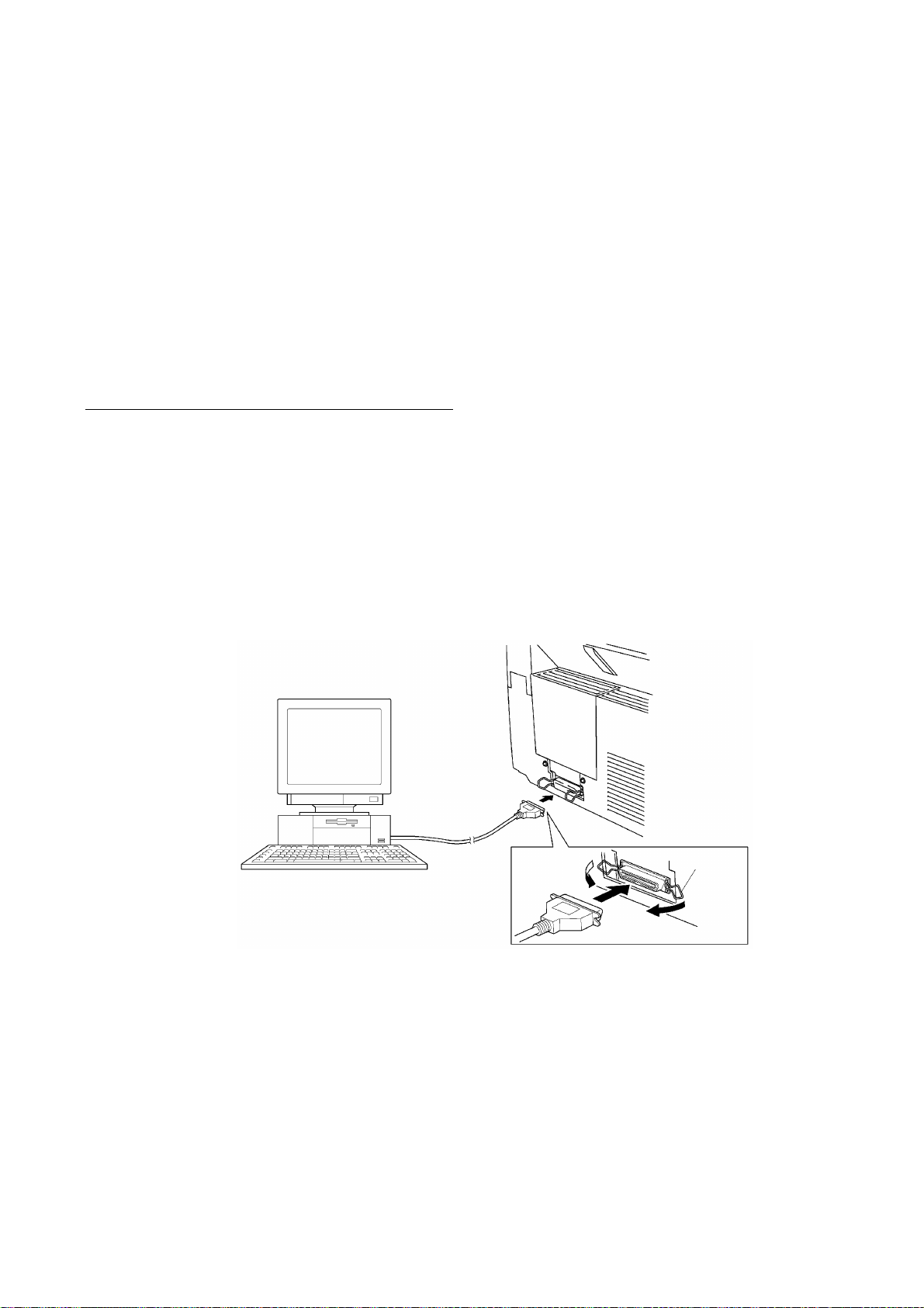
1. INSTALLING THE UPDATE DATA TO THE
FACSIMILE EQUIPMENT
If the program version is updated or the main PCB is replaced, install the update program onto the
flash ROM of the main PCB.
The program installation requires a host computer satisfying the following requirements:
- CPU Pentium 75 or higher
- RAM 8MB or greater (16MB recommended for Windows 95)
- OS Windows 3.1/3.11 or Windows 95
Connecting the equipment to your computer
(1) Make sure that the equipment's power cord is unplugged from a wall socket.
(2) Make sure that your computer is powered off.
(3) Connect the interface cable to the parallel interface port on the back of the equipment and
secure it with the lock wires.
(4) Connect the other end of the interface cable to the printer port of your computer and secure
it with the two screws.
(5) Power on your computer.
(6) Plug the equipment's power cord into a wall socket.
Host computer
Interface cable
Lock
wires
II - 1
Page 19

Installing the update data onto the flash ROM of the facsimile equipment
(1) Load the floppy disk which stores the update data and transfer utility into the floppy disk
drive of your computer.
(Or, copy the update data and transfer utility onto the same directory of the hard disk.)
(2) Click the Start button, point to Programs, and then click MS-DOS Prompt to open an MS-
DOS window.
(3) Type the drive letter where the update data and transfer utility are located. If it is a floppy
disk drive, type A:\ from the command line and press the ENTER key.
(4) Check that your computer is connected with the facsimile equipment correctly.
(5) To start the transfer utility transmitting the update data to the flash ROM of the facsimile
equipment, type the following:
A:\ICEN filename /b
Then press the ENTER key.
The equipment beeps and shows the "CONNECTING" on the LCD for one second.
Then, the equipment shows the "DOWNLOADING" on the LCD and starts receiving data
downloaded from the host computer.
During downloading, the equipment beeps intermittently.
Upon completion of the downloading, the equipment beeps continuously.
II - 2
Page 20

CHAPTER III.
THEORY OF OPERATION
Page 21

CONTENTS
1. OVERVIEW...........................................................................................................III-1
2. MECHANISMS......................................................................................................III-2
2.1 Scanner Mechanism.....................................................................................
2.1.1 Document feeding and ejecting mechanism..........................................
2.1.2 Scanner................................................................................................
2.2 Laser Printing Mechanism.............................................................................
2.2.1 Paper pulling-in, registration, feeding, and ejecting mechanism.............
2.2.2 Print process mechanism......................................................................
(1)Charging process..........................................................................
(2)Exposing process.........................................................................
(3)Developing process......................................................................
(4)Transferring process.....................................................................
(5)Erasing process............................................................................
2.2.3 Heat-fixing mechanism...........................................................................
2.3 Sensors and Actuators..................................................................................
3. CONTROL ELECTRONICS..................................................................................
III-3
III-3
III-3
III-4
III-4
III-6
III-7
III-7
III-8
III-8
III-8
III-9
III-10
III-12
3.1 Configuration................................................................................................
3.2 Main PCB.....................................................................................................
3.3 NCU PCB.....................................................................................................
3.4 Control Panel PCB........................................................................................
3.5 Power Supply PCB.......................................................................................
[ 1 ] Low-voltage power supply PCB....................................................
[ 2 ] High-voltage power supply PCB...................................................
III-12
III-13
III-15
III-17
III-18
III-18
III-19
Page 22
1. OVERVIEW
III - 1
*Not provided on the FAX-8250P/MFC-9050.
Page 23
2. MECHANISMS
The facsimile equipment is classified into the following mechanisms:
n SCANNER MECHANISM - Document feeding and ejecting mechanism
n LASER PRINTING MECHANISM - Paper pulling-in, registration, feeding, and ejecting
n SENSORS AND ACTUATORS
- Document scanning mechanism
mechanisms
- Print process mechanism (consisting of charging,
exposing, developing, transferring, and erasing
processes)
- Heat-fixing mechanism
Document feeding and
ejecting mechanism
SCANNER
Document scanning
mechanism
MECHANISM
Paper pulling-in and
registration mechanism
Print process
mechanism
LASER PRINTING MECHANISM
III - 2
Paper ejecting mechanism
Heat-fixing
mechanism
With paper feeding
mechanism
Page 24
2.1 Scanner Mechanism
2.1.1 Document feeding and ejecting mechanism
This mechanism consists of the document stacker, automatic document feeder (ADF), document
ejection roller ASSY, and document sensors. (For details about the sensors, refer to Section 2.3.)
If the operator sets documents on the document stacker and starts the scanning operation, the
scanner motor rotates so that the ADF (which consists of the separation roller and ADF parts)
feeds those documents into the equipment, starting from the bottom sheet to the top, page by
page. Each document advances with the document feed roller ASSY to the scanner, and then it is
fed out of the equipment with the document ejection roller ASSY.
2.1.2 Scanner
The scanner uses a contact image sensor (CIS) unit which consists of an LED array illuminating
documents, a self-focus lens array collecting the reflected light, a CIS PCB carrying out
photoelectric conversion to output picture element data, and a cover glass on which a document
advances. When the document passes between the document pressure bar and the cover glass,
it is scanned.
III - 3
Page 25
2.2 Laser Printing Mechanism
2.2.1 Paper pulling-in, registration, feeding, and ejecting mechanism
III - 4
Page 26
Paper pulling-in and registration mechanism
The paper pulling-in and registration mechanism consists of the pull-in roller gear (incorporated in
the multi-purpose sheet feeder), planetary gear system, paper feed solenoid, solenoid lever, clutch
release lever, and registration sensor. (For the details about the sensor, refer to Section 2.3.)
If the main motor rotates clockwise, the rotation is transmitted to the intermediate gear of the
planetary gear system. As the intermediate gear rotates, the pull-in roller drive gear also rotates
since the clutch gear is locked by the solenoid lever and the clutch release lever. Accordingly, the
pull-in roller in the multi-purpose sheet feeder rotates to pull in paper into the equipment, a sheet
at a time.
If the paper feed solenoid is retracted and the clutch release lever is operated according to the
cam profile of the pull-in roller gear so as to release the clutch gear, the clutch gear rotates and
the pull-in roller drive gear does not rotate. In this way, the clutch gear switches the transmission
of the motor rotation to the pull-in roller drive gear on and off.
The solenoid on/off timing and the clutch release lever timing allow this mechanism to pull in a
sheet and register it against the registration roller.
Paper feeding and ejecting mechanism
If the main motor rotates clockwise, the rotation is transmitted via the gear train to the drum drive
gear, heater roller drive gear, and paper ejection roller drive gear.
After the paper passes through the heat-fixing process, it will be ejected onto the paper tray.
If the leading edge of the paper pushes up the actuator of the paper ejection sensor, the
photosensor becomes opened, signaling the start of paper ejection. If the trailing edge has passed
through the sensor actuator, the sensor becomes closed, signaling the completion of paper
ejection. Then, the main motor stops rotation.
III - 5
Page 27
2.2.2 Print process mechanism
The print process unit works with laser beam, electrical charges, and toner. The graph below
shows the transition of electrical charge on the surface of the laser-sensitive drum through the five
processes: charging, exposing, developing, transferring, and erasing processes.
III - 6
Page 28
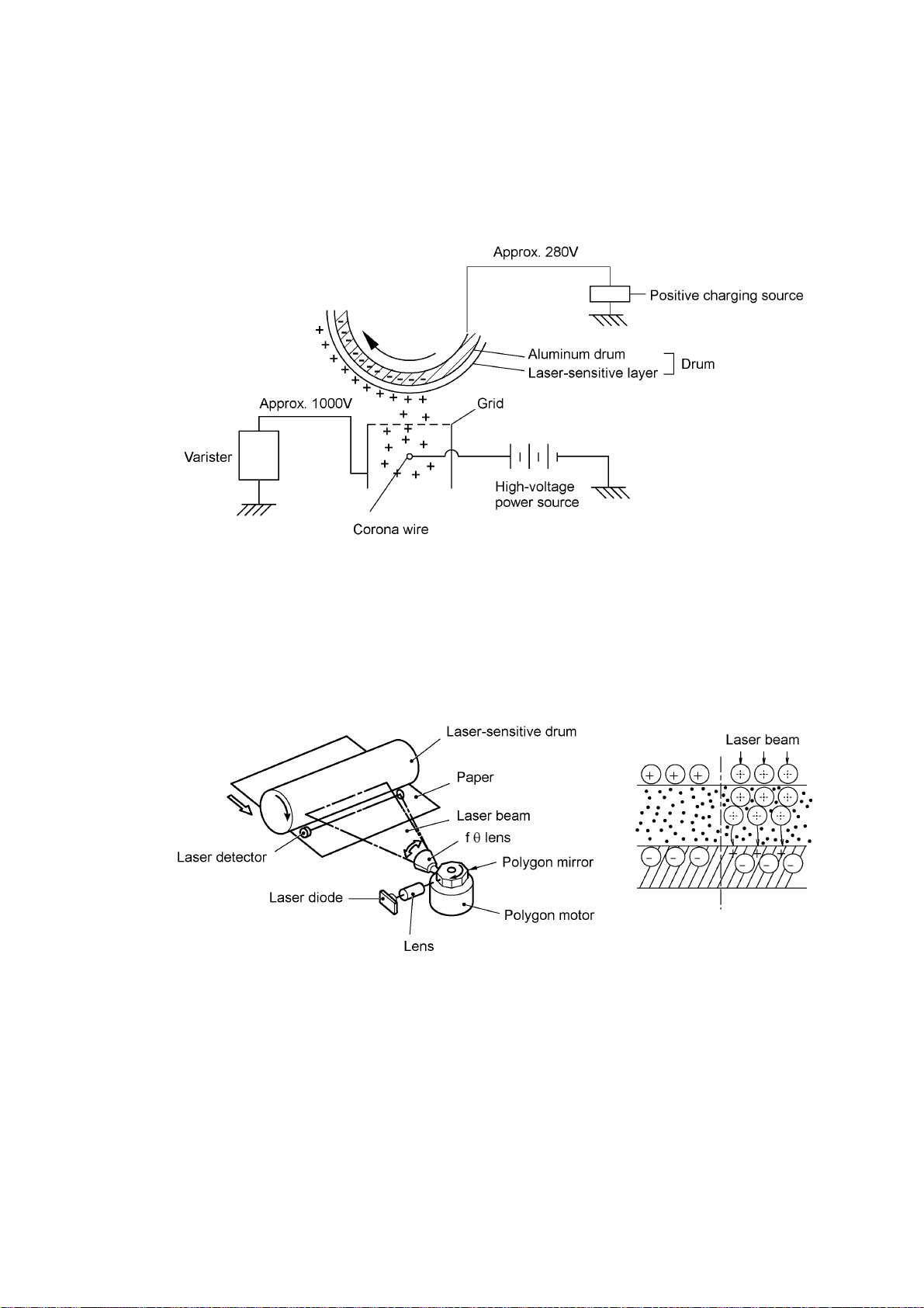
(1) Charging process
The high-voltage power supply applies DC bias to the corona wire to generate ion on the grid. The
ion uniformly charges the surface of the laser-sensitive drum to approx. 1000V which is kept by
the varister grounding the grid to the frame.
(2) Exposing process
When the laser-sensitive drum holds a positive electrical charge, the laser beam issued from the
laser unit scans the drum according to the print image to expose the drum surface for neutralizing
the spots where black should be, forming an electrostatic latent image.
III - 7
Page 29
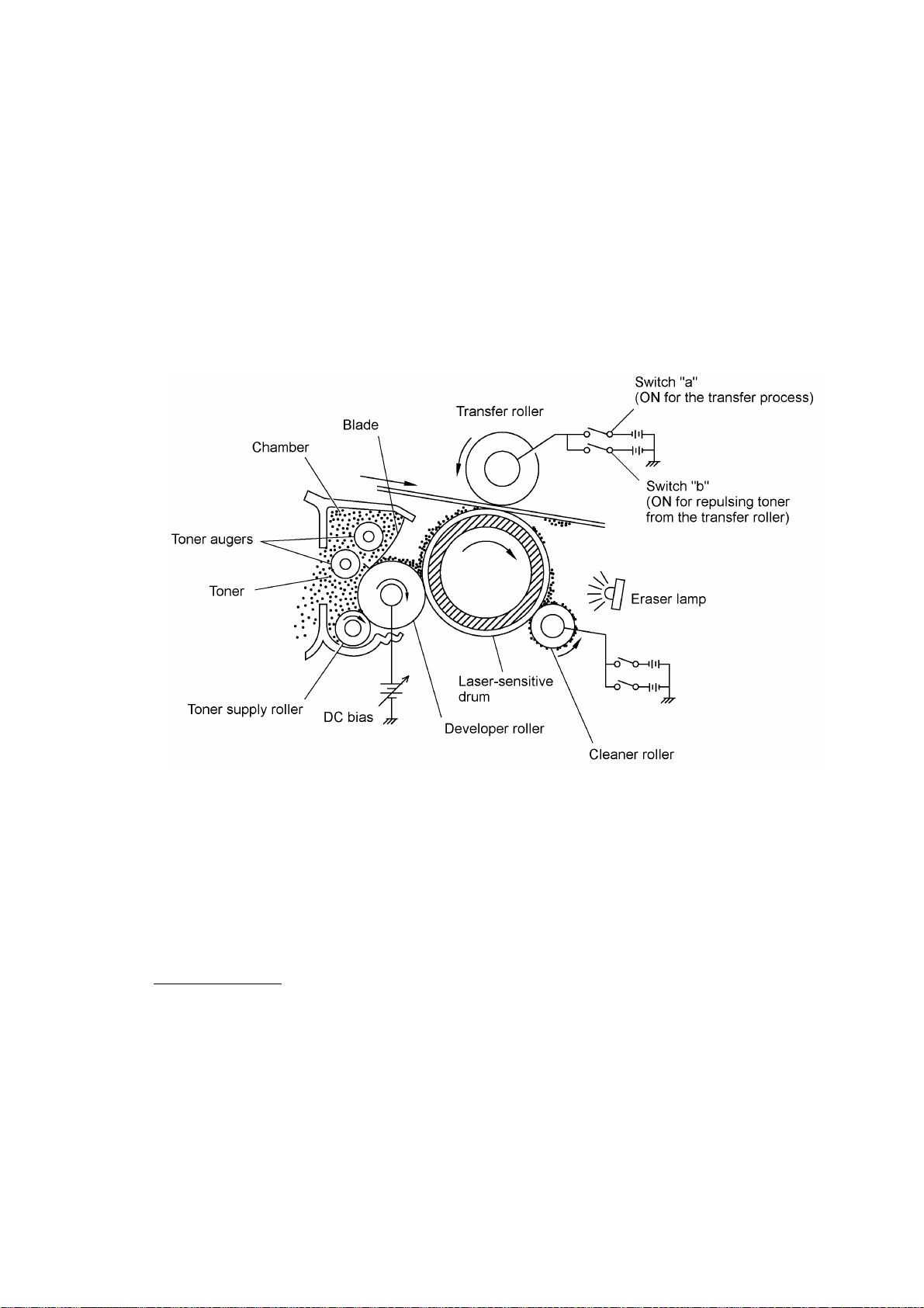
(3) Developing process
The developing process develops an electrostatic latent image formed on the drum in the
exposing process, into a toner image.
The developer roller attracts the toner particles fed from the toner cartridge by the toner supply
roller, and then conveys them to the contact section with the laser-sensitive drum
On the contact section between the developer roller and drum, the positive toner particles stick to
the neutralized spots on the drum according to the principles of attraction and repulsion,
transforming a latent image into a toner image.
The toner augers (which agitate toner particles in the chamber) and the blade allow toner particles
to be fed onto the developer roller at an even thickness.
(4) Transferring process
When a paper passes between the drum and the transfer roller, the switch "a" (see the above
illustration) is turned on to negatively charge the transfer roller. The toner is positive, so the toner
image formed on the drum will be transferred onto the paper according to the same principle as for
the developing process.
If the toner image fails to stick to the paper due to paper jam or other errors, it will stick to the
transfer roller. To repulse this toner, the switch "b" (see the above illustration) is turned on to
positively charge the transfer roller. The toner returns from the transfer roller to the drum.
Cleaning the drum
In the transferring process, not all the toner particles on the drum are transferred onto the paper
but some toner particles remain on the drum. The cleaner roller cleans the drum surface and
collects the residual toner. When printing starts or during non-printing, the toner collected on the
cleaner roller will be discharged onto the drum and returned to the chamber through the developer
roller for recycling in the subsequent developing process.
(5) Erasing process
The eraser lamp emits light to expose the drum surface, which erases the residual electrical
charge.
III - 8
Page 30
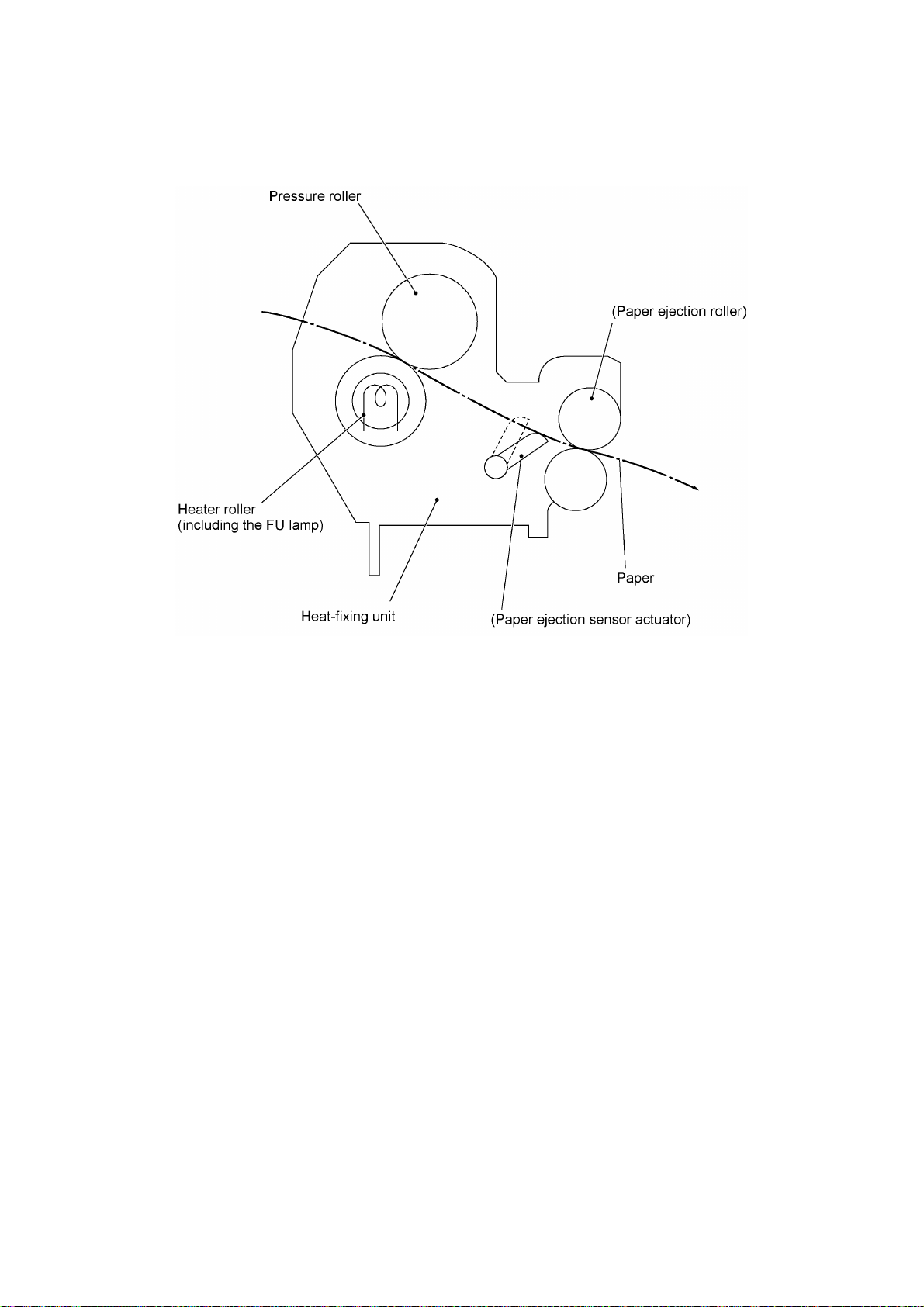
2.2.3 Heat-fixing mechanism
As the paper passes between the heater roller and the pressure roller in the heat-fixing unit, the
heater roller fuses the toner on the paper.
III - 9
Page 31

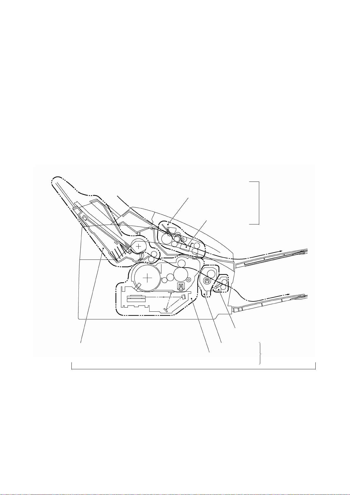
2.3 Sensors and Actuators
This equipment has ten sensors: seven photosensors, two thermisters and a mechanical switch as
described below.
Sensor name Type Located on
Document front sensor Photosensor Control panel PCB ASSY
Document rear sensor Photosensor Control panel PCB ASSY
Top cover sensor Photosensor Main PCB
Sheet feeder cover sensor Photosensor Main PCB
Registration sensor Photosensor Main PCB
Paper ejection sensor Photosensor High-voltage power supply
Toner sensor Photosensor Toner sensor PCB
Toner thermister Thermister Toner sensor PCB
Heater thermister Thermister Heat-fixing unit
Hook switch* Mechanical switch Hook switch PCB*
(Document sensor PCB)
(Document sensor PCB)
PCB
*Not provided on the FAX-8250P/MFC-9050.
• Document front sensor which detects the presence of documents.
• Document rear sensor which detects the leading and trailing edges of pages to tell the control
circuitry when the leading edge of a new page has reached the starting position and when the
scan for that page is over.
• Top cover sensor which detects whether the top cover is closed.
• Sheet feeder cover sensor which detects whether the sheet feeder cover is closed.
• Registration sensor which detects the leading and trailing edges of paper, which allows the
controller to determine the registration timing and check paper jam.
• Paper ejection sensor which detects whether the recording paper goes out of the equipment.
• Toner sensor which detects whether there is toner or a toner cartridge is loaded.
• Toner thermister which detects the ambient temperature of the toner cartridge.
• Heater thermister which detects the temperature of the heater roller of the fixing unit.
• Hook switch* which detects whether the handset is placed on the handset mount.
These photosensors are a photointerrupter consisting of a light-emitting diode and a light-sensitive
transistor. Each of them has an actuator separately arranged as shown on the next page.
III - 10
Page 32

*Not provided on the FAX-8250P/MFC-9050.
Location of Sensors and Actuators
III - 11
Page 33

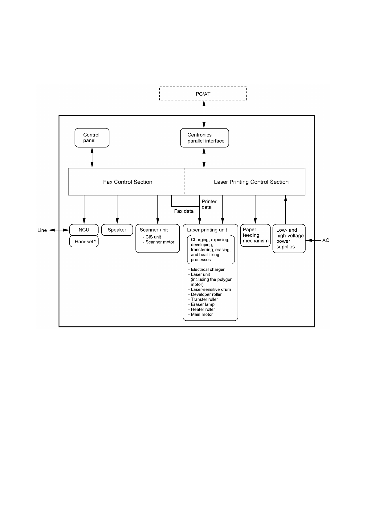
3. CONTROL ELECTRONICS
3.1 Configuration
The hardware configuration of the facsimile equipment is shown below.
(NOTE 1) Provided on the FAX-8250P/MFC-9050 (French version
(NOTE 2) Provided on the European, Australian, Indonesian, and Asian
only)/MFC-9550/MFC6650MC.
versions.
Configuration of Facsimile Equipment
III - 12
Page 34

3.2 Main PCB
The main PCB, which is the nucleus controlling the entire operation of the equipment, consists of a
FAX engine (ASIC), memories, MODEM, motor drive circuitry, sensor detection circuitry, and
analog circuits for scanning, printing, and power transmission shifting.
EEPROM:Electrically Erasable Programmable Read-only Memory
DRAM: Dynamic Random Access Memory
Block Diagram of Main PCB
III - 13
Page 35

III - 14
Page 36

3.3 NCU PCB
The NCU PCB switches the communications line to telephone or built-in MODEM, under the
control of the main PCB.
U.S.A. versions
III - 15
Page 37

European versions
III - 16
Page 38

3.4 Control Panel PCB
The control panel PCB and the main PCB communicate with each other by serially transmitting
commands and data.
The control panel unit consists of a gate array, an LCD and LEDs, which are controlled by the gate
array according to commands issued from the FAX engine on the main PCB.
The panel FPC is a flexible keyboard PCB which integrates the key matrix having rubber keytops.
Control Panel PCB and its Related Circuit
III - 17
Page 39

3.5 Power Supply PCB
[ 1 ] Low-voltage power supply PCB
The low-voltage power supply uses the switching regulation system to generate DC power (+5V
and +24V) from a commercial AC power supply for the driver circuits. The +5V source is fed to
the logic, control panel, sensors, CIS unit, etc. The 24V source is fed to the motors, solenoid, fan,
and high-voltage power supply PCB.
The low-voltage power supply also feeds AC power to the heater of the heat-fixing unit.
Low-voltage Power Supply Circuit
III - 18
Page 40

[ 2 ] High-voltage power supply PCB
This power supply generates high-voltage power sources from the 24V source fed from the lowvoltage power supply for charging, developing, and transferring in the laser printing process.
High-voltage Power Supply Circuit
III - 19
Page 41

CHAPTER IV.
DISASSEMBLY/REASSEMBLY AND
LUBRICATION
Page 42

CONTENTS
1. DISASSEMBLY/REASSEMBLY...........................................................................IV-1
n Safety Precautions..............................................................................................IV-1
Tightening Torque List........................................................................................IV-2
n Preparation.........................................................................................................IV-3
n How to Access the Object Component................................................................IV-3
n Disassembly Order Flow.....................................................................................IV-4
1.1 ROM Cover, Option Cover, and Battery ASSY*..............................................IV-5
1.2 Multi-purpose Sheet Feeder...........................................................................IV-7
1.3 Document Guide Base....................................................................................IV-8
1.4 Control Panel ASSY.......................................................................................IV-9
1.5 Panel Rear Cover and Control Panel..............................................................IV-10
1.6 Document Feed Roller ASSY and Document Ejection Roller ASSY................IV-13
1.7 Scanner Frame ASSY....................................................................................IV-14
1.8 Top Cover......................................................................................................IV-21
1.9 Handset Mount and Hook Switch PCB
Side Cover (for the FAX-8250P/MFC-9050)..............................................................IV-24
1.10 Heat-fixing Unit, FU Lamp, and Paper Ejection Sensor Actuator.....................IV-26
1.11 Laser Unit and Toner Sensor PCB..................................................................IV-28
1.12 Bottom Plate..................................................................................................IV-29
1.13 Low-voltage Power Supply PCB.....................................................................IV-31
1.14 Main PCB.......................................................................................................IV-32
1.15 High-voltage Power Supply PCB....................................................................IV-35
1.16 Fan.................................................................................................................IV-36
1.17 Registration Sensor Actuator, Sheet Feeder Cover Sensor Actuator, and
Top Cover Sensor Actuator............................................................................IV-37
1.18 Speaker..........................................................................................................IV-37
1.19 Gear Drive Unit..............................................................................................IV-38
1.20 NCU PCB.......................................................................................................IV-40
1.21 Scanner Grounding Plate...............................................................................IV-42
1.22 EL (Erase Lamp) Board..................................................................................IV-43
1.23 Cleaning of High-voltage Contacts and Grounding Contacts...........................IV-44
(for models except the FAX-8250P/MFC-9050)
i
Page 43

2. LUBRICATION......................................................................................................IV-45
[ 1 ] Document feed roller ASSY and document ejection roller ASSY.............IV-45
[ 2 ] Control panel locks.................................................................................IV-46
[ 3 ] Scanner frame ASSY and separation roller gear.....................................IV-46
[ 4 ] Top cover lock spring..............................................................................IV-47
[ 5 ] Gear drive unit........................................................................................IV-47
ii
Page 44

1. DISASSEMBLY/REASSEMBLY
nn Safety Precautions
To prevent the creation of secondary problems by mishandling, observe the following precautions
during maintenance work.
(1) Unplug the power cord from the power outlet before replacing parts or units. When having
access to the power supply, be sure to unplug the power cord from the power outlet.
(2) When servicing the optical system of the laser printing unit, be careful not to place
screwdrivers or other reflective objects in the path of the laser beam. Be sure to take off any
personal accessories such as wrist watches and rings before working on the printer. A
reflected beam, though invisible, can permanently damage your eyes.
(3) If the equipment has been printing, allow the heat-fixing unit sufficient time to cool down
before starting maintenance jobs. It is HOT!
(4) Be careful not to lose screws, washers, or other parts removed for parts replacement.
(5) Do not remove gears from the document LF roller ASSY or ejection roller ASSY if at all
possible. Once removed, they will become unusable and new gears will have to be put back
in.
(6) When using soldering irons and other heat-generating tools, take care not to damage the resin
parts such as wires, PCBs, and covers.
(7) Before handling the PCBs, touch a metal portion of the equipment to discharge static
electricity; otherwise, the electronic parts may be damaged due to the electricity charged in
your body.
(8) When transporting PCBs, be sure to wrap them in conductive sheets such as aluminum foil.
WARNING
For the FAX-8250P/MFC-9050 (French version only)/MFC-9550/MFC6650MC which has a NiMH battery on the main PCB, be sure to remove that battery before transporting the PCB (in
aluminum foil). Failure to do so may result in a short circuit, overcurrent flow, or fire.
(9) Be sure to reinsert self-tapping screws correctly, if removed.
(10) Tighten screws to the torque values listed on the next page.
(11) When connecting or disconnecting cable connectors, hold the connector bodies not the
cables. If the connector has a lock, always slide the connector lock to unlock it.
(12) Before reassembly, apply the specified lubricant to the specified points. (Refer to Section 2 in
this chapter.)
(13) After repairs, check not only the repaired portion but also that the connectors and other
related portions function properly before operation checks.
IV - 1
Page 45

Tightening Torque List
Location Screw type Q'ty Tightening torque Loosening torque
(kg•cm) (kg•cm)
Option cover Screw, pan (washer) M3x8DB 2 4 ±1 2 to 6
ADF parts Taptite, pan (washer) B M3x6 1 4 ±1 2 to 6
Panel rear cover Taptite, cup B M3x8 2 6 ±1 2 to 6
Scanner frame ASSY Taptite, cup B M3x10 2 9 ±2 2 to 6
Scanner motor Screw, pan (washer) M3x6DA 1 7 ±2 Min. 2
Scanner grounding leaf spring Taptite, cup S M3x6 1 7 ±2 Min. 2
CIS shield plate Taptite, cup S M3x6 1 7 ±2 Min. 2
Pinch roller leaf spring Taptite, cup B M3x8 1 8 ±2 Min. 2
Control panel locks Taptite, cup B M3x8 2 8 ±2 Min. 2
Scanner drive unit Taptite, cup B M3x8 1 8 ±2 Min. 2
Taptite, cup B M3x10 1 8 ±2 Min. 2
Top cover stopper Taptite, cup S M3x6 2 8 ±2 Min. 2
Hinges on top cover Taptite, bind B M4x12 4 10 ±2 3 to 6
Hinges on main cover Taptite, cup B M4x12 4 10 ±2 3 to 6
Handset mount Taptite, cup B M3x10 2 8 ±2 2 to 6
Heat-fixing unit Taptite, bind B M4x12 1 10 ±2 4 to 6
Laser unit Taptite, bind B M4x12 3 8 ±2 3 to 6
Toner sensor PCB Taptite, cup B M3x8 1 6 ±2 3 to 5
Bottom plate Taptite, bind B M4x12 7 10 ±2 3 to 6
Taptite, cup S M3x6 3 8 ±2 2 to 6
AC grounding wire Screw, pan (washer) M4x8DB 1 6 ±2 2 to 9
Interface connector Screw, pan M3x6 2 8 ±2 Min. 4
Low-voltage power supply PCB Taptite, cup S M3x6 1 8 ±2 2 to 6
Main PCB Taptite, bind B M4x12 1 10 ±2 2 to 6
High-voltage power supply PCB Taptite, bind B M4x12 1 10 ±2 3 to 6
Gear drive unit Taptite, cup B M4x20 3 12 ±2 3 to 6
Main motor Taptite, cup S M3x8 2 8 ±2 Min. 4
NCU bracket Taptite, bind B M4x12 1 10 ±2 3 to 6
NCU PCB Taptite, cup S M3x6 1 8 ±2 2 to 6
Scanner grounding plate Taptite, cup B M3x8 1 6 ±2 2 to 6
IV - 2
Page 46

nn Preparation
Prior to proceeding to the disassembly procedure,
(1) Unplug
- the modular jack of the telephone line,
- the modular jack of the curled cord (and remove the handset),
- the PC interface cable, and
- the modular jack of an external telephone set if connected. (Not shown below.)
(2) Remove
- the dust cover,
- the paper wire extension
- the document wire extension
- the document tray,
- the paper tray, and
- the drum unit (with the toner cartridge loaded)
nn How to Access the Object Component
• On the next page is a disassembly order flow which helps you access the object components.
To remove the gear drive unit, for example, first find it on the flow and learn its number ( in
this case). You need to remove parts numbered , , , , , and so as to access the
gear drive unit.
• Unless otherwise specified, the disassembled parts or components should be reassembled in
the reverse order of removal.
(*Not provided on the FAX-8250P/MFC-9050)
IV - 3
Page 47

nn Disassembly Order Flow
IV - 4
Page 48

1.1 ROM Cover, Option Cover, and Battery ASSY*
(*Provided on the FAX-8250P/MFC-9050 (French version only)/MFC-9550/MFC6650MC)
(1) As shown below, push down section "a" of the ROM cover and tilt it to the rear.
(2) Take off the option cover from the rear of the main cover by removing two screws "a." The
grounding wire also comes free.
IV - 5
Page 49

(3) FAX-8250P/MFC-9050 (French version only)/MFC-9550/MFC6650MC: To replace the battery
ASSY (Ni-MH battery), plug the power cord of the facsimile equipment into a power outlet,
disconnect the battery harness from the main PCB, and take out the battery ASSY while
pulling the battery support of the main cover in the direction of the arrow. Set a new battery
ASSY, connect the battery harness to the main PCB, and then unplug the power cord.
Disconnecting the battery harness with the power cord unplugged will lose the settings (e.g.,
calendar clock, voice messages, and received FAX data) stored in the RAM.
If you do not need to replace the battery ASSY but you will remove the main PCB in the
following procedures, take out the battery ASSY from its supports and put it on the main PCB
with the battery harness being connected.
(*Provided on the FAX-8250P/MFC-9050 (French version only)/
MFC-9550/MFC6650MC)
(** Provided on the European, Australian, Indonesian, and Asian
versions)
IV - 6
Page 50

1.2 Multi-purpose Sheet Feeder
(1) Open the top cover.
(2) Remove one of two screws from each of right and left top cover stoppers, and then fully open
the top cover.
(3) Pull either one of the right and left tabs provided on the main cover outwards and slightly lift
up the multi-purpose sheet feeder, then release the other end of the sheet feeder also.
nn Reassembling Notes
• When reinstalling the multi-purpose sheet feeder, fit the front end over the bosses provided on
the main cover and then push down the rear end.
IV - 7
Page 51

1.3 Document Guide Base
(1) Turn up the document guide base towards you.
(2) Push the right or left end of the document guide base inwards and take it off.
IV - 8
Page 52

1.4 Control Panel ASSY
(1) Slightly open the control panel ASSY.
(2) Push the right and left arms of the control panel ASSY outwards (in the direction of arrow •)
with your thumbs and open the control panel ASSY further (arrow ‚) to unhook those arms
from bosses “x” provided on the scanner frame ASSY. Then slide the control panel ASSY to
the front (arrow ƒ) to release its bosses “y” from the grooves of the scanner frame ASSY.
(3) Slightly lift up the control panel ASSY and disconnect the panel-main harness from the control
panel PCB.
IV - 9
Page 53

1.5 Panel Rear Cover and Control Panel
(1) Place the control panel ASSY upside down.
If you do not need to remove the ADF parts, anti-static brush, shield film, document pressure
bar, or document rear sensor actuator, skip to step (6).
(2) To remove the ADF parts (spring plates, separation rubber and anti-vibration rubber), remove
the screw.
(3) To replace the anti-static brush and shield film, remove them.
NOTE: Once removed, the anti-static brush and shield film will become unusable and new
parts will have to be put back in.
(4) To remove the document pressure bar, pull either of supports "a" provided on the panel rear
cover outwards and then lift the pressure bar up and towards the rear to release the three tabs
from the cutouts provided in the panel rear cover. The spring also comes off.
(5) To remove the document rear sensor actuator, pull either of supports "b" on the panel rear
cover outwards.
IV - 10
Page 54

(6) Remove the two screws from the panel rear cover.
(7) Unhook the panel rear cover from eight "X" latches provided on the control panel and lift up
the panel rear cover.
(8) Fully turn the document front sensor actuator to the rear and lift it up.
(9) Unhook the document sensor PCB from two "Y" latches.
(10) FAX2750/MFC-8250P/MFC4350/MFC-9050/MFC4650: Unhook the control panel PCB from
three "Z" latches.
MFC6650MC/MFC-9550: Unhook the MC PCB from "W" latch and then unhook the control
panel PCB from three "Z" latches.
(11) Slightly lift up the control panel PCB, then unlock the LCD cable connector and disconnect the
LCD flat cable. Next, unlock the FPC key connector and disconnect the FPC key.
IV - 11
Page 55

(12) As shown below, insert the tip of a flat screwdriver under clamp "A" from the rear and push up
clamp "A" slightly to release the LCD, and then take out the LCD while pulling the LCD flat
cable gently.
NOTE: Do not take out the LCD except when the LCD is defective and requires replacement.
nn Reassembling Notes
• Before reinstalling the LCD to the control panel, wipe fingerprints or dust off the LCD surface
and control panel window with a soft cloth.
• A new LCD is covered with a protection sheet. Before installing it, remove the protection sheet.
• To put the LCD back into place, insert the tip of a flat screwdriver under clamp "A" from the
rear, push up clamp "A" slightly, and then push the LCD to the rear with your thumbs.
IV - 12
Page 56

1.6 Document Feed Roller ASSY and Document Ejection Roller ASSY
(1) Lightly push down arm rib "a" and shift the document feed roller ASSY to the right and
upwards.
(2) Lightly push down arm rib "b" and shift the document ejection roller ASSY to the right and
upwards, without removing the shield film.
NOTE: Take care not to break the arm ribs. They may easily break.
nn Reassembling Notes
• Make sure that the shield film is on the document ejection roller gear and not bent down by that
gear.
• Once removed, the shield film will become unusable and new one will have to be put back in.
IV - 13
Page 57

1.7 Scanner Frame ASSY
(1) You can remove the following parts from the top of the scanner frame ASSY without taking
out the ASSY from the top cover.
• CIS film
• Shield film
• CIS unit (shown on the next page). Lightly pull up the arm, move the CIS unit to the left,
and lift up the right edge of the CIS unit. While holding up the CIS unit, disconnect the
CIS harness.
• CIS leaf springs (shown on the next page)
NOTE: Once removed, the CIS film and shield film will become unusable and new ones will
have to be put back in.
IV - 14
Page 58

(2) Open the top cover.
(3) Disconnect the scanner motor harness from the scanner motor ASSY without removing the
shield film.
IV - 15
Page 59

(4) Close the top cover.
(5) Remove the two screws from the scanner frame ASSY.
(6) Lift up the rear edge of the scanner frame ASSY to release the three pawls provided on the
front end from the top cover, then hold up the ASSY and disconnect the CIS harness (if the
CIS is mounted).
(7) Take off the grounding terminal by removing the screw.
IV - 16
Page 60

(8) Turn the scanner frame ASSY upside down.
(9) Remove the screw from the scanner motor and turn the motor clockwise to release from the
latch.
(10) Take off the scanner grounding leaf spring by removing the screw.
(11) Take off the CIS shield plate by removing the screw.
(12) Remove the pinch roller leaf spring, pinch rollers and shaft.
(13) Remove the control panel locks (leaf springs) by removing the screws.
IV - 17
Page 61

(14) Remove the pressure roller leaf springs by pulling them in the direction of arrows • and ‚ in
this order as shown below. Then remove the pressure rollers and shaft.
(15) Slightly push down the arm (in the direction of arrow •) and shift the separation roller gear to
the right (arrow ‚) when viewed from the rear. Then shift the separation roller to the right
(arrow ƒ) and take it up.
IV - 18
Page 62

(16) Take off the scanner drive unit by removing the two screws. The separation roller gear also
comes off.
(17) Push down the CIS side spring to release it from the latch, then pull it out to the right (when
viewed from the rear).
IV - 19
Page 63

nn Reassembling Notes
• When reinstalling the scanner motor, fit it in the latch provided on the scanner frame with the
connector facing up and then secure it with the screw. (See page IV-17.)
• When setting the scanner frame ASSY back into place,
- secure the grounding terminal to the scanner frame ASSY with the screw and route the
grounding wire around boss "x" (as shown on page IV-16),
- route the CIS harness through the scanner frame ASSY (or connect the CIS harness to the
CIS unit if mounted),
- route the panel-main harness through the cutout provided in the scanner frame ASSY.
• When reinstalling the CIS unit, first connect the CIS harness, insert the left end under the arm
of the scanner frame, put the CIS unit into the scanner frame, and move it to right (see the
illustration given on page IV-15).
• When attaching the CIS film, align the right, left and rear edges of the cutout with those
provided in the scanner frame and fit its two tabs into the scanner frame, as illustrated on page
IV-14.
• When connecting the scanner motor harness to the scanner motor connector, take care not to
bend the shield film.
• Once removed, the shield film becomes unusable and a new part will have to be put back in.
IV - 20
Page 64

1.8 Top Cover
(1) Open the top cover.
(2) Remove one of two screws from each of right and left top cover stoppers, and then fully open
the top cover.
(3) Pull the panel-main harness and CIS harness towards you.
(4) Remove the adhesive tape and pull the scanner motor harness and grounding wire towards
you.
IV - 21
Page 65

(5) Remove the four screws from the hinges R and L.
(6) Slightly lift up the top cover to release the bosses from the hinges and take it off to the rear.
(7) Remove the harness support sponges and take out the harnesses from the top cover.
IV - 22
Page 66

(8) Remove the two screws from each of the hinges R and L. The top cover stoppers also come
off.
nn Reassembling Notes
• When setting each hinge back into place, fit its tab in section "x" provided on the main cover.
• As illustrated on the previous page, route the scanner motor harness and grounding wire
through hooks "A1" of the top cover and through hooks "A2" of the main cover, and then fix
them with the support sponge. Route the panel-main harness and CIS harness through hooks
"B1" of the top cover and through hooks "B2" of the main cover, and then fix them with the
support sponge.
• When connecting the scanner motor harness to the scanner motor connector, take care not to
bend the shield film.
• Once removed, the shield film becomes unusable and a new part will have to be put back in.
IV - 23
Page 67

1.9 Handset Mount and Hook Switch PCB (for models except the FAX-8250P/MFC-9050)
Side Cover (for the FAX-8250P/MFC-9050)
(1) Open the top cover.
(2) Remove one of two screws from each of right and left top cover stoppers, then fully open the
top cover.
(3) Remove the two screws from the handset mount* or side cover**.
(4) Twist the handset mount* or side cover** so that it tilts over to the left and its upper end works
out of the bosses provided on the main cover.
NOTE: Do not pull the handset mount* away from the main cover. The hook switch harness*
is connected to the main PCB in the main cover.
*For models except the FAX-8250P/MFC-9050
**For the FAX-8250P/MFC-9050
IV - 24
Page 68

(5) Disassemble the handset mount by unhooking two latches "a" of the upper handset mount
with a flat screwdriver.
(6) Remove the hook switch PCB ASSY by unhooking latch "b."
(7) Disconnect the hook switch harness from the hook switch PCB
nn Reassembling Notes
• When assembling the upper and lower handset mounts, route the hook switch harness
underneath the hook switch PCB and through the cutout as shown above. Take care not to
pinch the harness between the upper and lower mounts.
IV - 25
Page 69

1.10 Heat-fixing Unit, FU Lamp, and Paper Ejection Sensor Actuator
(1) Open the top cover.
(2) Remove one of two screws from each of right and left top cover stoppers, then fully open the
top cover.
(3) Remove screw "a."
(4) Lift the left end of the heat-fixing unit up and to the left to release the right-hand boss from the
main cover, hold it up, and disconnect the heater harness (of the blue and brown heater
wires). Then disconnect the heater thermister harness from the EL (eraser lamp) board.
(5) Remove the paper ejection sensor actuator from the main cover.
IV - 26
Page 70

(6) To take out the FU lamp from the heat-fixing unit, remove two screws "b."
(7) Unhook the two latches outwards with the tip of a small flat screwdriver and open the upper
cover.
(8) Fully open the upper cover and remove it.
(9) Remove screw "d" and loosen screw "c."
(10) Hold the lock plate of the FU lamp between your fingers and pull out the FU lamp from the
heater roller.
CAUTION: Do not touch the FU lamp. If you have touched it, clean it thoroughly with
alcohol.
nn Reassembling Notes
• When setting the FU lamp into the heat-fixing unit, be sure to insert the right edge of the wire
into the folded lock plate.
• A new heat-fixing unit will be provided with the heater thermister harness being taped to the
unit. When installing the unit, remove the tape.
IV - 27
Page 71

1.11 Laser Unit and Toner Sensor PCB
(1) Remove the screw (Taptite, cup B M3x8) from the toner sensor PCB.
(2) Slightly lift up the toner sensor PCB and disconnect its harness.
(3) Remove the three screws from the laser unit.
(4) Slightly lift up the laser unit and disconnect the following from the main PCB:
- Laser diode harness (5-pin)
- Toner sensor harness (4-pin) if the toner sensor PCB is installed
- Polygon motor flat cable
NOTE: When handling the laser unit, take care not to touch the inside of the unit, glass, or
mirror.
NOTE: On the small PCB at the right side of the laser unit is a 2-pin connector which is for
the adjustment in the factory. Do not disturb it.
nn Reassembling Notes
• Before putting the laser unit back into place, check for any toner particles, paper dust or dirt,
and clean them out.
• When installing the laser unit, make sure that the laser diode harness, toner sensor harness
and polygon motor flat cable are routed as shown above.
• Make sure that the sponge is placed below the laser unit.
IV - 28
Page 72

1.12 Bottom Plate
(1) Turn the facsimile equipment upside down.
(2) Remove two screws "b" from the interface connector.
(3) Remove seven screws "c" and three screws "d" from the bottom plate.
(4) Slightly lift up the bottom plate, then take off the AC cord bushing and remove screw "e" from
the grounding terminal.
IV - 29
Page 73

nn Reassembling Notes
• When putting the bottom plate into place, secure the grounding wire to the bottom plate with
screw "e," fit the AC cord bushing into the cutout of the bottom plate, and fit the holes over the
bosses of the main cover. First tighten screws "b" (interface connector screws) and then
tighten screws "c" and "d."
• Once removed, the spacer will become unusable and new one will have to be put back in.
• When replacing the bottom plate with a new one, be sure to attach a new spacer to the new
bottom plate as specified below.
IV - 30
Page 74

1.13 Low-voltage Power Supply PCB
(1) Remove the screw from the low-voltage power supply PCB.
(2) Slightly lift up the low-voltage power supply PCB and disconnect it from the main PCB.
(3) Disconnect the heater harness (of the blue and brown wires) from the low-voltage power
supply PCB.
nn Reassembling Notes
• Be sure to route the heater harness through the three wire guides as illustrated above.
IV - 31
Page 75

1.14 Main PCB
(1) For the FAX-8250P/MFC-9050 (French version only)/MFC-9550/MFC6650MC, take the
battery ASSY*1 out of the supports at the rear of the main cover.
(2) Remove the screw from the main PCB.
(3) Slightly lift up the main PCB and disconnect it from the low-voltage power supply PCB.
(4) Disconnect the following harnesses from the main PCB:
• Speaker harness (2-pin, P7)
• Laser diode harness (5-pin, P6)
• Toner sensor harness (4-pin, P5)
• Polygon motor flat cable (5-pin, P4)
• NCU harness 2*2 (6-pin, P13)
• NCU harness (12-pin, P14)
• Solenoid harness (blue) (2-pin, P8)
• Hook switch harness*3 (red) (2-pin, P9)
• Main motor harness (6-pin, P16)
• High-voltage power supply harness (12-pin, P20)
• Fan harness (2-pin, P3)
• CIS harness (7-pin, P19)
• Scanner motor harness (5-pin, P17)
• Panel-main harness (6-pin, P21)
(*2 Provided on the European, Australian, Indonesian, and Asian versions.)
(*3 Not provided on the FAX-8250P/MFC-9050.)
*1 The FAX-8250P/MFC-9050 (French version only)/MFC-9550/MFC6650MC has a Ni-MH
battery ASSY. Only when you need to replace the main PCB, disconnect the battery harness.
After installing a new main PCB, you may need to make settings (e.g., calendar clock and
voice messages) to be stored in the RAM. If you need to replace the battery ASSY, do not
disconnect the harness in this disassembly step. Doing so with the power cord unplugged will
lose the settings stored in the RAM. Refer to Section 1.1.
nn Reassembling Notes
• Route the hook switch harness (red), solenoid harness (blue), and main motor harness through
three latches "w," "y" and "z."
• At the rear side of the main cover, route the harnesses as shown on the next page. Hook the
speaker harness on the left-hand battery support. For the FAX-8250P/MFC-9050 (French
version only)/MFC-9550/MFC6650MC, route the battery harness as shown on the next page to
hold the three harnesses (scanner motor harness, CIS harness and speaker harness) for
preventing the battery harness from interfering with the top cover sensor actuator.
• Tape the CIS harness and panel-main harness at location "a" and tape the scanner motor at
location "b" as shown on the next page.
• For the FAX-8250P/MFC-9050 (French version only)/MFC-9550/MFC6650MC, when transporting the main PCB, be sure to remove the battery ASSY (Ni-MH battery) from the PCB.
Failure to do so may result in a short circuit, overcurrent flow or fire.
• After you replace the main PCB, be sure to follow the flowchart given on page IV-34.
IV - 32
Page 76

*1Provided on the FAX-8250P/MFC-9050
(French version only)/MFC6650MC/MFC-9550.
*2Provided on the on the European, Australian,
Indonesian, and Asian versions.
*3Not provided on the FAX-8250P/MFC-9050.
IV - 33
Page 77

Setting up the main PCB after replacement
IV - 34
Page 78

1.15 High-voltage Power Supply PCB
(1) Remove the screw from the insulation film and high-voltage power supply PCB.
(2) Remove the insulation film.
(3) Slightly lift up the high-voltage power supply PCB and disconnect the main–high-voltage flat
cable.
(4) Disconnect the EL (eraser lamp) board harness and drum grounding harness from the high-
voltage power supply PCB.
nn Reassembling Notes
• Before reinstalling the high-voltage power supply PCB, check the high-voltage contacts for any
toner particles, paper dust or dirt, and clean them out.
• Be sure to route the drum grounding harness through boss "x" and latches "y" and "z."
• When putting the high-voltage power supply PCB back into place, first fit the cutout provided in
the PCB over "a" and insert the rear edge under "b," and then secure the PCB together with the
insulation sheet to the main cover with the screw.
IV - 35
Page 79

1.16 Fan
(1) If the main PCB is installed, remove the screw from the main PCB (refer to Section 1.14).
(2) Slightly lift up the main PCB and disconnect the fan harness from the main PCB.
(3) Take out the fan support.
(4) Pull up the fan.
nn Reassembling Notes
• Put the fan back into place with the non-sponge end facing up and with the label side facing
outwards.
• Route the fan harness through the harness guide as shown above.
IV - 36
Page 80

1.17 Registration Sensor Actuator, Sheet Feeder Cover Sensor Actuator, and Top Cover Sensor
Actuator
(1) Pull up the registration sensor actuator, sheet feeder cover sensor actuator, and top cover
sensor actuator.
1.18 Speaker
(1) Pull the speaker spring inwards and pull up the speaker.
nn Reassembling Notes
• Put the speaker into place with its harness facing to the front.
• Route the speaker harness through the latch as shown above.
IV - 37
Page 81

1.19 Gear Drive Unit
(1) Make sure that the heat-fixing unit is removed.
(2) Remove the three screws from the gear drive unit.
(3) Lift the gear drive unit up and out of the main cover.
IV - 38
Page 82

(4) To take off the motor cover and main motor, remove two screws "x."
(5) To take off the paper feed solenoid, solenoid lever, or clutch release lever, remove three
screws "y."
"x"
Taptite, cup
S M3x8
Motor cover
Main motor
Motor bracket
Solenoid
spring
Clutch release lever
Solenoid lever
Clutch release lever
Solenoid spring
Clutch spring
Solenoid lever
"y"
Taptite, cup
B M4x20
"y"
Gear 20/94
Gear drive unit
IV - 39
"y"
Pull-in roller
drive gear
Intermediate
gear
Clutch gear
Paper feed solenoid
Planetary
gear
system
Page 83

1.20 NCU PCB
(1) Make sure that the MJ cover, low-voltage power supply PCB and gear drive unit are removed.
(2) Remove the screw from the NCU bracket.
(3) Slightly lift up the NCU bracket (which holds the NCU PCB) and then disconnect the NCU
harness from the NCU PCB.
(* Provided on the European, Australian, Indonesian, and Asian versions.)
IV - 40
Page 84

(4) Remove the screw and take off the NCU PCB from the NCU bracket.
nn Reassembling Notes
• When setting the NCU PCB to the NCU bracket, fit its edges onto "b" and "c" and into "a" and
"d" as illustrated above.
• European, Australian, Indonesian, and Asian versions: First bind the NCU harness and NCU
harness 2 together with the ferrite core NF-80 so that the NF-80 comes near to the binder on
the NCU harness 2 as shown above, and connect those harnesses to the main PCB. Then
hook them to the two latches and route them between the two bosses as illustrated on the
previous page.
Other versions: Hook the NCU harness to the two latches and route it between the two bosses
as illustrated on the previous page.
(* Provided on the European, Australian, Indonesian, and Asian versions.)
IV - 41
Page 85

1.21 Scanner Grounding Plate
(1) Make sure that the heat-fixing unit is removed.
(2) Remove the screw from the scanner grounding plate and take it off. (If the bottom plate has
not been removed, remove front screw "c" also (see page IV-29) that secures both the
scanner grounding plate and bottom plate.)
(3) You may peel off the anti-static brush from the scanner grounding plate.
nn Reassembling Notes
• Once removed, the anti-static brush will become unusable and new one will have to be put
back in.
• Before attaching a new anti-static brush onto the scanner grounding plate, wipe the surface of
the attaching place with a cloth dampened with alcohol.
• When reinstalling the scanner grounding plate, fit it over the two bosses of the main cover.
IV - 42
Page 86

1.22 EL (Eraser Lamp) Board
Only when you need to replace the EL board (which is attached with double-sided adhesive tape),
remove it according to the steps below.
(1) Make sure that the EL board harness is disconnected from the high-voltage power supply
PCB. (Refer to Section 1.15.)
(2) Make sure that the heat-fixing unit is removed.
(3) Peel off the EL board from the main cover and clear adhesive tape if remaining.
nn Reassembling Notes
• When attaching a new EL board, bring the right end into contact with the boss provided on the
main cover.
IV - 43
Page 87

1.23 Cleaning of High-voltage Contacts and Grounding Contacts
If any toner particles, paper dust or dirt are on the contacts, clean them out. This will ensure that
power flows correctly to enable printing.
Grounding contacts High-voltage contacts
IV - 44
Page 88

2. LUBRICATION
Apply the specified lubricants to the lubrication points as shown below.
Lubricant type
(Manufacturer)
Molykote EM-30LG
or EM-30L
(Dow Corning)
Conductive grease
FLOIL GE676
(Kanto Kasei Ltd.)
Thin coat of grease
(1 mm3)
––––––– –––––––
Lubricant amount
Half of a rice-sized pinch of
grease (3 mm3)
[ 1 ] Document feed roller ASSY and document ejection roller ASSY
Rice-sized pinch
of grease (6 mm3)
IV - 45
Page 89

[ 2 ] Control panel locks
[ 3 ] Scanner frame ASSY and separation roller gear
IV - 46
Page 90

[ 4 ] Top cover lock spring
[ 5 ] Gear drive unit
IV - 47
Page 91

CHAPTER V.
MAINTENANCE MODE
Page 92

CONTENTS
1. ENTRY INTO THE MAINTENANCE MODE.........................................................V-1
2. LIST OF MAINTENANCE-MODE FUNCTIONS...................................................V-2
3. DETAILED DESCRIPTION OF MAINTENANCE-MODE FUNCTIONS................V-4
3.1 EEPROM Parameter Initialization...............................................................V-4
3.2 Printout of Scanning Compensation Data...................................................V-5
3.3 ADF Performance Test...............................................................................V-7
3.4 Test Pattern 1.............................................................................................V-8
3.5 Firmware Switch Setting and Printout.........................................................V-9
3.6 Operational Check of LCD..........................................................................V-51
3.7 Operational Check of Control Panel PCB...................................................V-51
3.8 Sensor Operational Check..........................................................................V-54
3.9 CIS Scanner Area Setting...........................................................................V-55
3.10EEPROM Customizing...............................................................................V-55
3.11Equipment Error Code Indication................................................................V-56
3.12Output of Transmission Log to the Telephone Line.....................................V-56
3.13Cancellation of the Memory Security Mode ................................................V-57
Page 93

1. ENTRY INTO THE MAINTENANCE MODE
FAX2750/MFC4350/MFC4650/MFC6650MC: To make the equipment enter the maintenance
mode, press the Function, *, 2, 8, 6, and 4 keys in this order.
Within 2 seconds
FAX-8250P/MFC-9050/MFC-9550: To make the equipment enter the maintenance mode, press
the Menu, *, 2, 8, 6, and 4 keys in this order.
Within 2 seconds
The equipment beeps for approx. one second and displays " " on the
LCD, indicating that it is placed in the initial stage of the maintenance mode, a mode in which the
equipment is ready to accept entry from the keys.
To select one of the maintenance-mode functions listed in Section 2, enter the corresponding 2digit function code with the numerical keys on the control panel. (The details of each
maintenance-mode function are described in Section 3.)
NOTES: • Pressing the 9 key twice in the initial stage of the maintenance mode makes the
equipment exit from the maintenance mode, restoring it to the standby state.
• Pressing the Stop key after entering only one digit restores the equipment to the
initial stage of the maintenance mode.
• If an invalid function code is entered, the equipment resumes the initial stage of the
maintenance mode.
V - 1
Page 94

2. LIST OF MAINTENANCE-MODE FUNCTIONS
Maintenance-mode Functions
Function
Code Function
01 EEPROM Parameter Initialization 3.1 (V-4)
02
03
04
05 Printout of Scanning Compensation Data 3.2 (V-5)
06
07
08 ADF* Performance Test 3.3 (V-7)
09 Test Pattern 1 3.4 (V-8)
10 Firmware Switch Setting 3.5 (V-9)
11 Printout of Firmware Switch Data 3.5 (V-50)
12 Operational Check of LCD 3.6 (V-51)
13 Operational Check of Control Panel PCB
14
15
32 Sensor Operational Check 3.8 (V-54)
55 CIS Scanner Area Setting 3.9 (V-55)
74 EEPROM Customizing 3.10 (V-55)
82 Equipment Error Code Indication 3.11 (V-56)
87 Output of Transmission Log to the Telephone Line 3.12 (V-56)
91 EEPROM Parameter Initialization (except the telephone number
99 Exit from the Maintenance Mode ---- (V-1)
(Check of Keys and Buttons)
storage area)
Reference
Subsection
(Page)
3.7 (V-51)
3.1 (V-4)
V - 2
* ADF: Automatic document feeder
Page 95

- - - - - - - - - - - - - - - - - - - - - - - - - - IMPORTANT - - - - - - - - - - - - - - - - - - - - - - - - - - - - - - - -
Basically, the maintenance-mode functions listed on the previous page should be accessed by
service personnel only. However, you may allow end users to access some of these under the
guidance of service personnel (e.g., by telephone).
The user-accessible functions (codes 10, 11, 12, 82, 87 and 91) are shaded in the table given on
the previous page. Function code 10 accesses the firmware switches WSW01 to WSW36, each
of which has eight selectors. You should not allow end users to access all of those selectors, but
you may allow them to access user-accessible selectors which are shaded in the firmware switch
tables in Subsection 3.5.
The service personnel should instruct end users to follow the procedure given below.
(1) FAX2750/MFC4350/MFC4650/MFC6650MC: Press the Function and Mode keys in this
order.
FAX-8250P/MFC-9050/MFC-9550: Press the Menu and Mode keys in this order.
The LCD clears the current display.
NOTE: The Mode key is inoperable during standby for redialing and timer.
(2) Press the 0 key.
(3) Enter the desired function code (10, 11, 12, 82, 87, or 91) with the numerical keys.
For function code 10, access the desired firmware switch according to the operating
procedure described in Subsection 3.5.
(4) To make the equipment return to the standby state, press the Stop key.
Function/Menu key
Mode key
0 key
Stop key
V - 3
Page 96

3. DETAILED DESCRIPTION OF
MAINTENANCE-MODE FUNCTIONS
3.1 EEPROM Parameter Initialization
nn Function
The equipment initializes the parameters, user switches, and firmware switches registered in the
EEPROM, to the initial values. Entering the function code 01 initializes all of the EEPROM areas,
but entering 91 does not initialize some areas, as listed below.
Function code
Data item
Maintenance-mode functions
User switches
Firmware switches
Remote activation code
Activity report
Station ID data
Outside line number
Telephone function registration
One-touch dialing
Speed dialing
Group dialing
EEPROM customizing code
(4-digit)
NOTE: If you replace the main PCB with one used for other facsimile equipment, carry out this
procedure and then customize the EEPROM (maintenance-mode function code 74 in Section
3.10).
(Note that the first digit of the 4-digit code will be
initialized to "0." If the code is 1001, for example, it
will be initialized to 0001.)
01 91
These will be
initialized
All of these will be.
initialized
These will not be
initialized
This will not be initialized.
nn Operating Procedure
(1) Press the 0 and 1 keys (or the 9 and 1 keys according to your need) in this order in the initial
stage of the maintenance mode.
The "PARAMETER INIT" will appear on the LCD.
(2) Upon completion of parameter initialization, the equipment returns to the initial stage of the
maintenance mode.
V - 4
Page 97

3.2 Printout of Scanning Compensation Data
nn Function
The equipment prints out the white and black level data for scanning compensation.
nn Operating Procedure
Do not start this function merely after powering on the equipment but start it after carrying out a
sequence of scanning operation. Unless the equipment has carried out any scanning operation,
this function cannot print out correct scanning compensation data. This is because at the start of
scanning operation, the equipment initializes white and black level data and takes in the scanning
compensation reference data.
(1) Press the 0 and 5 keys in this order in the initial stage of the maintenance mode.
The "WHITE LEVEL 1" will appear on the LCD.
(2) The equipment prints out the scanning compensation data list containing the following:
a) 2-value quantization white level data (208 bytes)
b) 2-value quantization black level data (1 byte)
c) LED light intensity value, 2-value quantization LED light intensity value, and photo mode
LED light intensity value (3 bytes)
d) 2-value quantization A/D-high and photo-mode A/D-high values (2 bytes)
e) Compensation data for background color (1 byte)
(3) Upon completion of recording of the compensation data list, the equipment returns to the
initial stage of the maintenance mode.
NOTE: When the equipment prints monochrome images after monochrome scanning, only the
green data is valid.
NOTE: If any data is abnormal, its code will be printed in inline style, as shown on the next page.
V - 5
Page 98

Scanning Compensation Data List
V - 6
Page 99

3.3 ADF Performance Test
nn Function
The equipment counts the documents fed by the automatic document feeder (ADF) and displays
the count on the LCD for checking the ADF performance.
nn Operating Procedure
(1) Set documents. (Allowable up to the ADF capacity.)
The "DOC. READY" will appear on the LCD.
(2) Press the 0 and 8 keys in this order.
While counting the documents, the equipment feeds them in and out, displaying the current
count on the LCD as shown below.
(3) After showing the final count, the equipment beeps for one second. To return the equipment
to the initial stage of the maintenance mode, press the Stop key.
Current count (1st page in this example)
V - 7
Page 100

3.4 Test Pattern 1
nn Function
This function, much like the copying function, prints out test pattern 1 to allow the service
personnel to check for record data missing or print quality.
nn Operating Procedure
Press the 0 and 9 keys in this order in the initial stage of the maintenance mode.
The figure below shows test pattern 1.
Test Pattern 1
V - 8
 Loading...